US4493316A - Articulating knee stabilizer - Google Patents
Articulating knee stabilizerDownload PDFInfo
- Publication number
- US4493316A US4493316AUS06/474,004US47400483AUS4493316AUS 4493316 AUS4493316 AUS 4493316AUS 47400483 AUS47400483 AUS 47400483AUS 4493316 AUS4493316 AUS 4493316A
- Authority
- US
- United States
- Prior art keywords
- knee
- hinge
- stabilizer
- shell
- gear
- Prior art date
- Legal status (The legal status is an assumption and is not a legal conclusion. Google has not performed a legal analysis and makes no representation as to the accuracy of the status listed.)
- Expired - Lifetime
Links
Images
Classifications
- A—HUMAN NECESSITIES
- A61—MEDICAL OR VETERINARY SCIENCE; HYGIENE
- A61F—FILTERS IMPLANTABLE INTO BLOOD VESSELS; PROSTHESES; DEVICES PROVIDING PATENCY TO, OR PREVENTING COLLAPSING OF, TUBULAR STRUCTURES OF THE BODY, e.g. STENTS; ORTHOPAEDIC, NURSING OR CONTRACEPTIVE DEVICES; FOMENTATION; TREATMENT OR PROTECTION OF EYES OR EARS; BANDAGES, DRESSINGS OR ABSORBENT PADS; FIRST-AID KITS
- A61F5/00—Orthopaedic methods or devices for non-surgical treatment of bones or joints; Nursing devices ; Anti-rape devices
- A61F5/01—Orthopaedic devices, e.g. long-term immobilising or pressure directing devices for treating broken or deformed bones such as splints, casts or braces
- A61F5/0102—Orthopaedic devices, e.g. long-term immobilising or pressure directing devices for treating broken or deformed bones such as splints, casts or braces specially adapted for correcting deformities of the limbs or for supporting them; Ortheses, e.g. with articulations
- A61F5/0123—Orthopaedic devices, e.g. long-term immobilising or pressure directing devices for treating broken or deformed bones such as splints, casts or braces specially adapted for correcting deformities of the limbs or for supporting them; Ortheses, e.g. with articulations for the knees
- A—HUMAN NECESSITIES
- A41—WEARING APPAREL
- A41D—OUTERWEAR; PROTECTIVE GARMENTS; ACCESSORIES
- A41D13/00—Professional, industrial or sporting protective garments, e.g. surgeons' gowns or garments protecting against blows or punches
- A41D13/015—Professional, industrial or sporting protective garments, e.g. surgeons' gowns or garments protecting against blows or punches with shock-absorbing means
- A41D13/0153—Professional, industrial or sporting protective garments, e.g. surgeons' gowns or garments protecting against blows or punches with shock-absorbing means having hinged or separable parts
- A—HUMAN NECESSITIES
- A61—MEDICAL OR VETERINARY SCIENCE; HYGIENE
- A61F—FILTERS IMPLANTABLE INTO BLOOD VESSELS; PROSTHESES; DEVICES PROVIDING PATENCY TO, OR PREVENTING COLLAPSING OF, TUBULAR STRUCTURES OF THE BODY, e.g. STENTS; ORTHOPAEDIC, NURSING OR CONTRACEPTIVE DEVICES; FOMENTATION; TREATMENT OR PROTECTION OF EYES OR EARS; BANDAGES, DRESSINGS OR ABSORBENT PADS; FIRST-AID KITS
- A61F5/00—Orthopaedic methods or devices for non-surgical treatment of bones or joints; Nursing devices ; Anti-rape devices
- A61F5/01—Orthopaedic devices, e.g. long-term immobilising or pressure directing devices for treating broken or deformed bones such as splints, casts or braces
- A61F5/0102—Orthopaedic devices, e.g. long-term immobilising or pressure directing devices for treating broken or deformed bones such as splints, casts or braces specially adapted for correcting deformities of the limbs or for supporting them; Ortheses, e.g. with articulations
- A61F2005/0132—Additional features of the articulation
- A61F2005/0137—Additional features of the articulation with two parallel pivots
- A61F2005/0139—Additional features of the articulation with two parallel pivots geared
- A—HUMAN NECESSITIES
- A61—MEDICAL OR VETERINARY SCIENCE; HYGIENE
- A61F—FILTERS IMPLANTABLE INTO BLOOD VESSELS; PROSTHESES; DEVICES PROVIDING PATENCY TO, OR PREVENTING COLLAPSING OF, TUBULAR STRUCTURES OF THE BODY, e.g. STENTS; ORTHOPAEDIC, NURSING OR CONTRACEPTIVE DEVICES; FOMENTATION; TREATMENT OR PROTECTION OF EYES OR EARS; BANDAGES, DRESSINGS OR ABSORBENT PADS; FIRST-AID KITS
- A61F5/00—Orthopaedic methods or devices for non-surgical treatment of bones or joints; Nursing devices ; Anti-rape devices
- A61F5/01—Orthopaedic devices, e.g. long-term immobilising or pressure directing devices for treating broken or deformed bones such as splints, casts or braces
- A61F5/0102—Orthopaedic devices, e.g. long-term immobilising or pressure directing devices for treating broken or deformed bones such as splints, casts or braces specially adapted for correcting deformities of the limbs or for supporting them; Ortheses, e.g. with articulations
- A61F2005/0132—Additional features of the articulation
- A61F2005/0165—Additional features of the articulation with limits of movement
- A61F2005/0167—Additional features of the articulation with limits of movement adjustable
Definitions
- the present inventionrelates to an orthopedic support device, and particularly pertains to a polycentric knee stabilizer capable of rendering full support and stability to the knee joint at rest and in motion.
- the human kneeis the largest joint of the body, but due to its natural structure is the most vulnerable.
- the legconsists principally of a lower bone called the tibia and an upper bone known as the femur.
- the femur and the tibiaare hinged together at the knee joint which consists of the femural condyles supported in engagement with bearing like pads positioned on the upper end of the tibia called the medial and lateral menisci.
- the jointis held together by numerous ligaments, muscles and tendons, including the lateral ligaments and internal ligaments.
- the patellais a similarly supported bone positioned in front knee joint primarily acting as a shield for it.
- the axes above which the natural movement between the tibia and femur takes placeshifts backward.
- the axesshifts forwardly.
- the knee jointhas a locking feature when the joint is in full extension. This latter feature permits the knee joint to be capable of supporting great weight vertically.
- the jointis susceptible to damage if over extended or subjected to lateral or rotational trauma. If one or more of the ligaments or other elements of the knee structure are damaged, the joint may become unstable, allowing the knee joint to wobble laterally, move forward or backward, or rotate about its generally vertical axis. Corrective surgery may also result in knee joint instability particularly during the healing process.
- the components of the knee jointare capable of self-healing if the joint is maintained in a suitable stable position for a proper period of time. It is also important for recovery to have the support for the healing joint elements equipped with means for permitting controlled movement when exercising the joint elements to restore their strength and natural range. It is often necessary for particular individuals, such as athletes, to continue their activity and strenuous occupations despite inherent weakness in a knee joint due to prior trauma or during recuperation. It is desirable therefore to provide support and protection to the knee joint for such persons during periods when it is subject to further injury.
- the same devicebe effective in controlling the range of knee movement in flexion, extension and rotation, and be readily adjustable during use to establish and maintain the desired movement of the joint within the natural range of rotation in a manner that simulates the shifting rotational axes of a normal knee.
- Applicant's inventionmeets these and other requirements and overcomes the deficiencies of available knee stabilizers.
- a firm fitting thigh shell and calf shellattach the stabilizer anteriorly above and below a knee joint of the wearer.
- the shellsare made from lightweight high impact resistant plastic, and conformed to the shape of the wearer's thigh and calf.
- graphite reenforced composite shellsare especially advantageous. They are provided with lateral and medial extensions in way of the knee joint to support it on both sides.
- the interior surfaces of the shellsare formed with a cushioning layer of resilient material having a textured surface bearing against the skin. The resilient layer provides for both added protection and comfort in wearing of the knee stabilizer.
- the shellsenclose approximately one-half of the circumference of the thigh and calf and are held firmly in place by wide extensible straps attachable posteriorly between the lateral and medial sides of the shells.
- the form and fit of the shells to the legcooperate with other elements of the stabilizer to prevent independent rotation of the femur and tibia.
- the thigh and calf shellsare hingedly joined together at their lateral and medial sides adjacent to the knee joint by hinge assemblies.
- Each such assemblyincludes a pair of parallel strength links rotatably connecting corresponding sides of the shells together by means of pivot pins located at each end of the links.
- the linksprotect the hinge assemblies and provide great lateral strength for the stabilizer.
- Hinge gears attached to the thigh and calf shellsare rotatably mounted on the pivot pins and spaced between the strength links. The teeth of the respective hinge gears mesh at the mid-length of the links.
- the thigh and calf shellsmay freely rotate about their respective pivot pin axes yet have their rotational motion integrated by the meshing of the hinge gears to simulate the polycentric axes of rotation of the natural knee joint.
- the meshed gearsalso prevent one shell from moving anteriorly or posteriorly and rotating medially or laterally in relation to the other shell.
- a pinion stop gearis rotatably mounted upon the periphery of each hinge gear.
- the stop gearsare supported by arm members that are selectively rotatable about the respective hinge pivot pin axes.
- the stop gear teethmesh with those of the hinge gears.
- the pinion gearsrotate with the hinge gears, their selected position on the hinge gears controls the integrated rotation of the two hinge gears by permitting rotation of the latter gears unless it is stopped by the locking mesh of the teeth of one stop gear with the teeth of the opposite hinge gear.
- One of the pinion stop gearsis selected to control the permissible flexion of the knee stabilizer, while the other stop gear controls extension.
- a stabilizerthat is light in weight and comfortable to wear, while at the same time supplying great strength and stability to a knee joint against potentially damaging forces in all planes.
- the stabilizerpermits full flexion and extension of the knee in the manner of a natural knee joint, even during strenuous activity.
- the stabilizerprecisely and smoothly controls the degree of flexion and extension of the knee joint. Such limits may be changed by quick and easy adjustment of the stabilizer hinge mechanism without the removal of the stabilizer.
- the stabilizercan also accomodate a rotational misalignment between the femur and tibia of the wearer, or be adjusted to provide a torque to remedy such a condition. Because of its design and construction, the stabilizer poses minimal constraint upon the activity of a wearer while supplying maximum support.
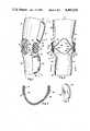
- FIG. 1is perspective view of the complete stabilizer
- FIG. 2is a front view of the unit without the retaining straps
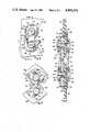
- FIG. 3is an enlarged sectional view taken along line 3--3 of FIG. 2;
- FIG. 4is an enlarged side elevation view of the hinge connection
- FIG. 5is a side elevation view as seen from the inside of the stabilizer of FIG. 4, with the knee in a bent position;
- FIG. 6is an enlarged sectional view taken on line 6--6 of FIG. 4.
- the knee stabilizer 10is illustrated in FIG. 1 as it would be attached to the thigh 12 and calf 14 of the right leg of a wearer.
- Thigh shell 16is secured to the thigh 12 by extendable strap 18 employing hook and loop attachments 20 located on the lateral and medial sides of the shell 16.
- Calf shell 22is similarly secured to calf 14 by means of strap 24 and hook and loop attachment 26.
- Hinge assembly 28is installed on the medial side of the stabilizer joining the thigh shell 16 and the calf shell 22 by means of pivot pins 30 and 32.
- a lateral hinge assemblyis illustrated at 34.
- the hinge assemblies 28 and 34are of identical construction, but have a right and left handed orientation depending upon the side of the stabilizer 10 upon which they are mounted.
- the general arrangement of the hinge assemblies 28 and 34, and their principal components,are illustrated in FIGS. 1 and 2. A detailed description of a hinge assembly will be subsequently given with reference to hinge assembly 28 as being typical.
- the construction of the thigh and calf shell 16 and 22 and their interconnection by the hinge assemblies 28 and 34are illustrated in FIGS. 2 and 3.
- the shellsare constructed of graphite composite plastic for lightweight and high impact resistance. They are formed to conform to the shape of the thigh 12 and the calf 14 of the wearer.
- the shellshave a C-shaped configuration and are positioned anteriorly on the leg, extending approximately halfway around the thigh and calf.
- the thigh shell 16has downward medial and lateral extensions 36 to support the sides of the knee joint.
- the calf shell 22has upward extensions 38 for the same purpose.
- the opening 40 between the shell 16 and 22is provided to accomodate the patella of the knee joint.
- the contour and extent of the shellsis further depicted in FIG.
- FIG. 3which illustrates a sectional view of the calf shell 22.
- the interior surfaces of the shells 16 and 22are lined with a layer of cushioning material as illustrated by the layer 42 covering the interior surface 44 of calf shell 22.
- the cushioning layeris formed of neoprene.
- Condyle pads 46are removably mountable to the hinge assemblies 28 and 34 with mounting clips 48 as depicted in FIGS. 2 and 7.
- the pads 46are formed of plastic and are shaped to the contours of the knee of the wearer.
- FIGS. 1 and 2The principal components of a typical hinge assembly 28 are illustrated in FIGS. 1 and 2.
- the hingeincludes a pair of parallel stainless steel links 50 and 52.
- the structure and function of the interior link 52 in hinge assembly 28can be better understoood by reference to the corresponding link 54 of hinge assembly 34 as it is depicted in FIG. 1.
- the links 50 and 52are rotatably connected at their ends to the extensions 36 of thigh shell 16 and extensions 38 of calf shell 22 by pivot pins 30 and 32 respectively.
- the pivot pinspass through holes in the shells.
- the elements of the hinge assembly 28are contained between links 50 and 52 and are held together by pivot pins 30 and 32.
- the small holes 51 in the linksaccomodate the condyle pad mounting clips 48 (FIGS. 2 and 7).
- Meshing hinge gears 56 and 58, pinion stop gear arms 60 and 62are rotatably mounted upon pivot pins 30 and 32 on the medial side of shell extension 36 and 38 between the shells and link 50.
- Pinion stop gears 61 and 63are mounted at the ends of the arms 60 and 62 and mesh with the hinge gears 56 and 58.
- Annular bushings 64 and 66provide bearing surfaces for the rotation of the link 50 about the axes of the pivot pins 30 and 32.
- bushing 64 and 66The length of bushing 64 and 66 is greater than the width of ink 50 to provide working space for rotation of the link when the links are tightly drawn together by the pivot pins as will be subsequently described.
- Shim washers 68 and 70are rotatably mounted on pivot pins 30 and 32 on the lateral side of the shell extensions 36 and 38 between the shells and the link 52. The shape and attachment of the washers 68 and 70 provide for better distribution of lateral stress over the shell.
- Lateral bushings 72 and 74perform the same function as their opposite counterpart bushings 64 and 66.
- Hinge gears 56 and 58are also secured to the thigh shell extension 36 and the calf shell extension 38 by rotational adjustments screws 76 and 78 respectively (FIGS. 4 and 6).
- the adjustment screwspass through one of a series of holes 80 and 82 which are drilled in an arc through the hinge gears 56 and 58, and through a single hole 84 and 86 respectively in shell extensions 36 and 38.
- the shim bearing arms 68 and 70are attached to the lateral sides of the shell by means of the screws 76 and 78. Screws 76 and 78 are held in place by being threaded into T-nuts 88 and 90.
- Pivot pins 30 and 32are T-shaped elements having broad heads 92 and shaft sections 94 which pass through the openings in shell extensions 36 and 38.
- the shaft sectionshave a threaded interior well 96.
- Retaining caps 98mount upon the ends of the shaft sections, and are secured thereon by hinge locking screws 100 which are threadable into the wells 96.
- hinge gear 56, pinion stop gear arm 60, pinion stop gear 61, and shim washer 68rotate together about pivot pin 30.
- calf shell 22, hinge gear 58, pinion stop gear arm 62, pinion stop 63, and shim washer 70rotate together about pivot pin 32.
- pinion stop gear arms 60 and 62may be manually rotated about the pivot pins to selectively position stop gears 61 and 63 on the circumference of hinge gears 56 and 58.
- the pinion stop gear armscan no longer rotate independently, and are locked in position.
- Applicants' hinge designprovides novel knee stabilizer features together with fineness of control through full flexion and extension not previously available.
- Use of two points of rotation at the ends of the steel links 50 and 52 to join the thigh shell 16 and calf shell 22provide great lateral strength for the stabilizer.
- the designallows polycentric rotation between the shells, thus emulating the varying axes of rotation of a natural knee.
- the position of pinion stop gear 61limits knee extension, while the position of pinion stop gear 63 controls the permitted amount of flexion. Limits of rotation are established by first manually positioning the pinion stop gears 61 and 63 on the circumference of the hinge gears 56 and 58. Gears 61 and 63 will then ride upon the hinge gears with which they mesh until they encounter and engage the teeth of the opposite hinge gear, thus preventing further rotation of the hinge.
- pinion stop gear 61is illustrated in locking engagement with the calf hinge gear 58 preventing further rotational extension between the shells 16 and 22.
- pinion stop gear 63is illustrated in engagement with the thigh shell gear 56 limiting flexion rotation between the thigh and calf sheels. It is apparent that the pinion stop gears 61 and 63 may be positioned to lock the stabilizer 10 in any desired position.
- the diameter and pitch of the hinge gears 56 and 58have been selected to provide spacing for natural polycentric rotation of the knee, smooth fine control, strength, and minimal pinion stop gear profile.
- the hinge gears 56 and 58are 48 pitch gears having a diameter of one and one-half inches.
- An additional important feature of applicants' stabilizer designis its ability to accomodate and support a knee that is rotational misaligned about the axis of the extended tibia and femur, or to induce rotation to properly align a knee that has a tendency toward misalignment. This is achieved by the ability to establish a controlled degree of rotational misalignment between the thigh shell 16 and calf shell 22 by varying the attachment positions of the hinge gears of the stabilizer as illustrated in FIG. 4. In the usual aligned stabilizer as illustrated in FIG. 1 and by the full lines in the lower half FIG. 4, the rotational adjustment screw 76 and the adjustment screw 78 are placed in the centermost of the mounting holes 80 and 82.
- varying clockwise or counter-clockwise rotational displacement between the shell 16 and the calf shell 22may be established by the selection of an off center hinge gear mounting hole 80 and 82 on any one, or all four of the hinge gears to their respective shells. Rotation of each gear supplying one quarter of the displacement. As illustrated in FIG. 4, a clockwise rotational displacement, as viewed from above the thigh shell, has been established between shell 16 and 22. This is done by changing the attachment hole used in securing hinge gear 58 to the shell extension 38 to rotate hinge gear 58 clockwise as viewed from outside the stabilizer 10.
- the wearerfirst positions the hinge gears on one side of the stabilizer 10 to establish any rotational misalignment desired between the thigh shell 16 and calf shell 22.
- locking screws 100are slackened, and the pinion stop gears 61 and 63 are positioned for the desired extension and flexion.
- the locking screws 100are then firmly tightened to lock the pinion stop gear arms 60 and 62 in place. Similar adjustment would be made in hinge assembly 34.
- condyle pads 46With condyle pads 46 in place, shells 16 and 22 are placed on the anterior of wearer's thigh and calf above and below the knee joint, and firmly secured in place with extensible straps 18 and 24 using hook and loop attachments 20 and 26.
- hinge locking screws 100may be accomplished by merely slackening hinge locking screws 100, changing the positions of the pinion stop gears 61 and 63 and retightening the hinge locking screws 100.
Landscapes
- Health & Medical Sciences (AREA)
- Nursing (AREA)
- Orthopedic Medicine & Surgery (AREA)
- Engineering & Computer Science (AREA)
- Biomedical Technology (AREA)
- Heart & Thoracic Surgery (AREA)
- Vascular Medicine (AREA)
- Life Sciences & Earth Sciences (AREA)
- Animal Behavior & Ethology (AREA)
- General Health & Medical Sciences (AREA)
- Public Health (AREA)
- Veterinary Medicine (AREA)
- Orthopedics, Nursing, And Contraception (AREA)
- Prostheses (AREA)
Abstract
Description
Claims (12)
Priority Applications (1)
| Application Number | Priority Date | Filing Date | Title |
|---|---|---|---|
| US06/474,004US4493316A (en) | 1983-03-10 | 1983-03-10 | Articulating knee stabilizer |
Applications Claiming Priority (1)
| Application Number | Priority Date | Filing Date | Title |
|---|---|---|---|
| US06/474,004US4493316A (en) | 1983-03-10 | 1983-03-10 | Articulating knee stabilizer |
Publications (1)
| Publication Number | Publication Date |
|---|---|
| US4493316Atrue US4493316A (en) | 1985-01-15 |
Family
ID=23881830
Family Applications (1)
| Application Number | Title | Priority Date | Filing Date |
|---|---|---|---|
| US06/474,004Expired - LifetimeUS4493316A (en) | 1983-03-10 | 1983-03-10 | Articulating knee stabilizer |
Country Status (1)
| Country | Link |
|---|---|
| US (1) | US4493316A (en) |
Cited By (104)
| Publication number | Priority date | Publication date | Assignee | Title |
|---|---|---|---|---|
| US4554913A (en)* | 1983-11-07 | 1985-11-26 | Scott Orthopedics, Inc. | Adjustable joint for a knee brace |
| US4632097A (en)* | 1985-05-13 | 1986-12-30 | Brooks Richard R | Knee brace |
| US4635623A (en)* | 1983-10-24 | 1987-01-13 | J. E. Hanger Limited | Brace for an articulating limb |
| US4697583A (en)* | 1985-01-29 | 1987-10-06 | Don Joy Orthopedic, Inc. | Four-point anterior cruciate ligament brace |
| US4715363A (en)* | 1986-09-26 | 1987-12-29 | Detty Garnett E | Knee brace with extension angle establishing means |
| US4732143A (en)* | 1987-02-13 | 1988-03-22 | Spectrum Orthopedics, Ltd. | Selectable extension stop for a polycentric hinge |
| US4751748A (en)* | 1986-03-04 | 1988-06-21 | The Gold Belt Line, Inc. | Shin guards |
| US4802467A (en)* | 1988-05-09 | 1989-02-07 | Timothy Pansiera | Bi-centric knee joint support |
| US4825852A (en)* | 1986-10-31 | 1989-05-02 | Sutter Biomedical, Inc. | Continuous passive motion device |
| US4844057A (en)* | 1987-11-16 | 1989-07-04 | David Hoy | Knee orthotic hinge joint |
| US4856501A (en)* | 1987-06-29 | 1989-08-15 | Innovation Sports, Inc. | Knee brace having adjustable width frame pivoted to cuffs |
| US4873967A (en)* | 1987-04-27 | 1989-10-17 | Sutherland Jeffrey L | Knee orthosis |
| US4881299A (en)* | 1987-02-18 | 1989-11-21 | Young David E | Orthopaedic and orthotic bi-pivotal hinge with improved adjustment means |
| US4886054A (en)* | 1987-06-29 | 1989-12-12 | Innovation Sports, Inc. | Knee brace with cammed stop lever |
| US4915098A (en)* | 1985-04-18 | 1990-04-10 | Protectair Limited | Orthopaedic hinge mechanism |
| US4928676A (en)* | 1989-02-27 | 1990-05-29 | Timothy Pansiera | Knee brace with flexible secondary joint |
| US4928670A (en)* | 1988-12-06 | 1990-05-29 | Delorenzo Richard | Human knee joint stabilizing orthosis with semi-rigid, substantial encasement means for lower leg |
| US4947838A (en)* | 1989-02-27 | 1990-08-14 | Donato Giannetti | Shell-like orthopedic brace |
| US4966133A (en)* | 1988-09-08 | 1990-10-30 | Kausek James H | Knee brace for control of ligament stability |
| EP0401170A1 (en)* | 1989-05-30 | 1990-12-05 | Marc Vanden Broeck | Joint mechanism for pair of orthotic supports |
| US4982734A (en)* | 1988-05-07 | 1991-01-08 | Penlon Limited | Anaesthesia equipment |
| USRE33621E (en)* | 1983-10-03 | 1991-06-25 | Anatomic brace fracture for the knee | |
| USD318736S (en) | 1989-09-05 | 1991-07-30 | Innovation Sports, Inc. | Athletic knee brace |
| US5036837A (en)* | 1990-02-09 | 1991-08-06 | Bio-Tec, Inc. | Dynamic extension splint |
| US5038763A (en)* | 1989-09-15 | 1991-08-13 | Wiggins Christopher N | Knee brace |
| US5092320A (en)* | 1991-03-19 | 1992-03-03 | Empi, Inc. | Knee brace with magnetic securing means |
| US5133341A (en)* | 1991-03-01 | 1992-07-28 | Samuel Singer | Knee brace with posterior strut |
| US5148606A (en)* | 1989-02-08 | 1992-09-22 | Don Joy, Inc. | Leg measuring device |
| DE4137056A1 (en)* | 1991-11-11 | 1993-05-13 | Biedermann Motech Gmbh | ORTHOSIC JOINT |
| DE4137057A1 (en)* | 1991-11-11 | 1993-05-13 | Biedermann Motech Gmbh | ADJUSTABLE ORTHOSIS JOINT |
| US5211273A (en)* | 1986-01-22 | 1993-05-18 | Hybo Science, Inc. | Axial thrust clutch/bearing/freewheel |
| US5219053A (en)* | 1985-01-24 | 1993-06-15 | Hybo Science, Inc. | Unidirectional clutch with shell races |
| US5222582A (en)* | 1986-01-22 | 1993-06-29 | Hybo Science, Inc. | Double hyperboloidal-type clutch |
| US5222733A (en)* | 1991-06-18 | 1993-06-29 | Brunty Steven H | Throwing arm training device |
| US5399154A (en)* | 1993-06-30 | 1995-03-21 | Empi, Inc. | Constant torque range-of-motion splint |
| US5403002A (en)* | 1991-06-18 | 1995-04-04 | Brunty; Steven H. | Throwing arm training device |
| USD357070S (en) | 1994-01-24 | 1995-04-04 | Castillo Edward L | Orthopedic knee brace |
| US5419754A (en)* | 1993-02-05 | 1995-05-30 | Robert Johnson | Knee brace |
| US5437619A (en)* | 1993-06-30 | 1995-08-01 | Empi, Inc. | Range-of-motion splint with eccentric spring |
| US5443444A (en)* | 1994-07-19 | 1995-08-22 | Professional Care Products Incorporated | Orthopaedic polycentric hinge |
| US5472410A (en)* | 1994-04-22 | 1995-12-05 | Deroyal/Lmb, Inc. | Adjustable flexion and extension joint orthoses |
| US5520627A (en)* | 1993-06-30 | 1996-05-28 | Empi, Inc. | Range-of-motion ankle splint |
| WO1996018439A1 (en)* | 1994-12-13 | 1996-06-20 | O' I'kai'ka Kino, Incorporated | Basketball practice aid |
| US5571078A (en)* | 1993-06-30 | 1996-11-05 | Empi, Inc. | Range-of-motion ankle splint |
| US5658241A (en)* | 1990-02-09 | 1997-08-19 | Ultraflex Systems, Inc. | Multi-functional dynamic splint |
| US5676640A (en)* | 1995-04-07 | 1997-10-14 | Biedermann Motech Gmbh | Orthesis joint system |
| US5759165A (en)* | 1993-06-30 | 1998-06-02 | Empi, Inc. | Forearm supination range-of-motion orthosis |
| US5772618A (en)* | 1996-05-31 | 1998-06-30 | Breg, Inc. | Hinge for an orthopedic brace |
| US5946187A (en)* | 1997-09-23 | 1999-08-31 | International Business Machines Corporation | Heat pipe arrangement for enhancing the cooling capacity of a laptop computer |
| US6117164A (en)* | 1997-06-06 | 2000-09-12 | Dj Orthopedics, Llc | Flexible multijoint therapeutic pads |
| USD433756S (en)* | 1999-11-02 | 2000-11-14 | Castillo Edward L | Osteoarthritis knee brace |
| WO2000074946A1 (en)* | 1999-06-04 | 2000-12-14 | Dj Orthopedics, Llc | Orthopedic knee braces having sublimated graphics |
| US20020107465A1 (en)* | 2001-01-29 | 2002-08-08 | Brad Freeman | Joint brace with rapid-release securement members |
| US20020107462A1 (en)* | 2001-02-02 | 2002-08-08 | Brad Freeman | Anatomical joint brace with adjustable joint extension limiter |
| US6461318B2 (en) | 2001-01-29 | 2002-10-08 | Brad Freeman | Anatomical brace with rapid-release securement members |
| US6464657B1 (en) | 2000-05-24 | 2002-10-15 | James D. Castillo | Anatomical joint brace field of the invention |
| US20020183674A1 (en)* | 2000-01-18 | 2002-12-05 | Castillo Edward L. | Osteo-arthritis knee brace |
| US20030153853A1 (en)* | 2002-02-15 | 2003-08-14 | Houser Guy M. | Bicentric hinge for use in a brace |
| US6623439B2 (en) | 2001-08-31 | 2003-09-23 | Dj Orthopedics, Llc | Contoured knee brace frame |
| US6689080B2 (en) | 2000-05-24 | 2004-02-10 | Asterisk.Asterisk Llc | Joint brace with limb-conforming arcuately adjustable cuffs |
| US20040158184A1 (en)* | 2003-01-16 | 2004-08-12 | Davis Perry H. | Orthopedic splint |
| US20040267177A1 (en)* | 2003-06-30 | 2004-12-30 | Houser Guy M. | Knee brace with dynamic counterforce |
| US20050148915A1 (en)* | 2004-01-07 | 2005-07-07 | Nathanson Jeremy J. | Knee brace hinges having dual axes of rotation |
| US20050148916A1 (en)* | 2004-01-07 | 2005-07-07 | Nathanson Jeremy J. | Knee brace hinges with adaptive motion |
| US6962571B2 (en) | 2001-02-02 | 2005-11-08 | Asterisk.Asterisk, Llc | Joint brace with multi-planar pivoting assembly and infinitely adjustable limb extension regulator |
| US20050273025A1 (en)* | 2004-05-19 | 2005-12-08 | Houser Guy M | Braces having an assembly for exerting a manually adjustable force on a limb of a user |
| USD517248S1 (en) | 2004-10-12 | 2006-03-14 | Asterisk.Asterisk, Llc | Patella cup protector |
| US7044925B2 (en) | 2002-12-30 | 2006-05-16 | Innovation Sports, Llc | Hinge system for regulating knee joint flexion and extension |
| US20060161267A1 (en)* | 2005-01-14 | 2006-07-20 | Clausen Arinbjorn V | Method and apparatus for applying mirror-printed film to a prosthetic or orthotic device and device having the same |
| US20060287624A1 (en)* | 2005-06-21 | 2006-12-21 | William Popp | Orthopedic polycentric hinge |
| US20070100265A1 (en)* | 2003-12-12 | 2007-05-03 | The Regents Of The University Of Colorado, A Body Corporate | Non-surgical correcting abnormal knee loading |
| US20070163025A1 (en)* | 2004-08-25 | 2007-07-19 | Travel Caddy, Inc. D/B/A Travelon | Knee Pad Constructions |
| US20070270976A1 (en)* | 2002-04-25 | 2007-11-22 | Ultraflex Systems, Inc. | Ambulating ankle & knee joints with bidirectional dampening and assistance using elastomeric restraint |
| US20080188784A1 (en)* | 2000-02-22 | 2008-08-07 | Ceriani Dylann D | Hinge assembly for an orthopedic knee brace and knee brace incorporating the hinge assembly |
| US20080195014A1 (en)* | 2007-02-12 | 2008-08-14 | Arni Thor Ingimundarson | Orthopedic component for use with an orthopedic brace |
| US7488300B2 (en) | 2002-02-15 | 2009-02-10 | Thusane | Bicentric hinge for use in a brace |
| USD588753S1 (en) | 2008-02-12 | 2009-03-17 | Ossur Hf | Patella protector assembly |
| US20090198162A1 (en)* | 2002-04-25 | 2009-08-06 | Ultraflex Sytems, Inc. | Ambulating knee joint |
| US20100056970A1 (en)* | 2008-08-28 | 2010-03-04 | Nace Richard A | Knee orthosis |
| US20100243830A1 (en)* | 2009-03-24 | 2010-09-30 | Asustek Computer Inc. | Electronic Device |
| US20110071449A1 (en)* | 2009-09-18 | 2011-03-24 | Duane A. Kuhler | Fulcrum Knee Brace |
| US8882689B2 (en) | 2010-12-20 | 2014-11-11 | Asterisk.Asterisk, Llc | Knee brace |
| US9149709B1 (en)* | 2014-09-30 | 2015-10-06 | Wilson Sporting Goods Co. | Hinged articulating catcher leg guard |
| US20170119569A1 (en)* | 2015-10-30 | 2017-05-04 | Ossur Iceland Ehf | Hinge assembly for an orthopedic device |
| US9668903B2 (en) | 2014-11-20 | 2017-06-06 | Ossur Iceland Ehf | Polymeric polycentric hinge |
| US9857849B1 (en) | 2016-06-10 | 2018-01-02 | Microsoft Technology Licensing, Llc | Hinged device with wrapped displays |
| US10227808B2 (en) | 2015-11-20 | 2019-03-12 | Microsoft Technology Licensing, Llc | Hinged device |
| US10241548B2 (en) | 2016-12-09 | 2019-03-26 | Microsoft Technology Licensing, Llc | Computing device employing a self-spacing hinge assembly |
| US10253804B2 (en) | 2017-01-24 | 2019-04-09 | Microsoft Technology Licensing, Llc | Hinged device |
| US10296044B2 (en) | 2017-06-08 | 2019-05-21 | Microsoft Technology Licensing, Llc | Hinged device |
| US10344510B2 (en) | 2017-06-16 | 2019-07-09 | Microsoft Technology Licensing, Llc | Hinged device |
| US10364598B2 (en) | 2016-09-02 | 2019-07-30 | Microsoft Technology Licensing, Llc | Hinged device |
| US10420668B2 (en) | 2014-11-20 | 2019-09-24 | Ossur Iceland Ehf | Patella cup |
| US10474203B2 (en) | 2016-09-01 | 2019-11-12 | Microsoft Technology Licensing, Llc | Hinged device |
| US10641318B2 (en) | 2016-12-09 | 2020-05-05 | Microsoft Technology Licensing, Llc | Hinged device |
| US10682785B1 (en) | 2017-01-24 | 2020-06-16 | William Stuart | Method for producing a negative cast for a brace with corrective forces to control PLC deficiencies |
| US10758392B2 (en) | 2016-05-31 | 2020-09-01 | United Surgical, Inc. | Flexion and extension range limiting hinge for an orthopedic brace |
| WO2020243688A1 (en)* | 2019-05-31 | 2020-12-03 | Kilbey Bryan E | Inflatable flexion-correcting knee brace |
| US11096803B2 (en) | 2016-12-06 | 2021-08-24 | Ossur Iceland Ehf | Movable joint for use in a prosthetic or orthopedic system |
| US20230021158A1 (en)* | 2019-09-19 | 2023-01-19 | Daryl BODNER | Knee brace |
| US11839564B1 (en) | 2019-08-08 | 2023-12-12 | Preferred Prescription, INC | Knee orthosis, adjustable |
| US11918500B1 (en) | 2020-03-31 | 2024-03-05 | Preferred Prescription, Inc. | Hinged knee brace with double upper strap arrangement |
| US12121463B1 (en) | 2020-02-13 | 2024-10-22 | Preferred Prescription, Inc. | Knee/elbow brace |
| US12178729B2 (en) | 2019-03-26 | 2024-12-31 | Ossur Iceland Ehf | Hinge assembly for an orthopedic device |
Citations (3)
| Publication number | Priority date | Publication date | Assignee | Title |
|---|---|---|---|---|
| US3898697A (en)* | 1973-11-13 | 1975-08-12 | Charles C Whitehead | Knee protective gear |
| US4372298A (en)* | 1981-07-20 | 1983-02-08 | U.S. Manufacturing Co. | Knee brace |
| US4381768A (en)* | 1981-05-18 | 1983-05-03 | Stainless Mfg., Inc. | Knee orthosis |
- 1983
- 1983-03-10USUS06/474,004patent/US4493316A/ennot_activeExpired - Lifetime
Patent Citations (3)
| Publication number | Priority date | Publication date | Assignee | Title |
|---|---|---|---|---|
| US3898697A (en)* | 1973-11-13 | 1975-08-12 | Charles C Whitehead | Knee protective gear |
| US4381768A (en)* | 1981-05-18 | 1983-05-03 | Stainless Mfg., Inc. | Knee orthosis |
| US4372298A (en)* | 1981-07-20 | 1983-02-08 | U.S. Manufacturing Co. | Knee brace |
Cited By (135)
| Publication number | Priority date | Publication date | Assignee | Title |
|---|---|---|---|---|
| USRE33621E (en)* | 1983-10-03 | 1991-06-25 | Anatomic brace fracture for the knee | |
| US4635623A (en)* | 1983-10-24 | 1987-01-13 | J. E. Hanger Limited | Brace for an articulating limb |
| US4554913A (en)* | 1983-11-07 | 1985-11-26 | Scott Orthopedics, Inc. | Adjustable joint for a knee brace |
| US5219053A (en)* | 1985-01-24 | 1993-06-15 | Hybo Science, Inc. | Unidirectional clutch with shell races |
| US4697583A (en)* | 1985-01-29 | 1987-10-06 | Don Joy Orthopedic, Inc. | Four-point anterior cruciate ligament brace |
| US4915098A (en)* | 1985-04-18 | 1990-04-10 | Protectair Limited | Orthopaedic hinge mechanism |
| US4632097A (en)* | 1985-05-13 | 1986-12-30 | Brooks Richard R | Knee brace |
| US5211273A (en)* | 1986-01-22 | 1993-05-18 | Hybo Science, Inc. | Axial thrust clutch/bearing/freewheel |
| US5222582A (en)* | 1986-01-22 | 1993-06-29 | Hybo Science, Inc. | Double hyperboloidal-type clutch |
| US4751748A (en)* | 1986-03-04 | 1988-06-21 | The Gold Belt Line, Inc. | Shin guards |
| US4715363A (en)* | 1986-09-26 | 1987-12-29 | Detty Garnett E | Knee brace with extension angle establishing means |
| US4825852A (en)* | 1986-10-31 | 1989-05-02 | Sutter Biomedical, Inc. | Continuous passive motion device |
| US4732143A (en)* | 1987-02-13 | 1988-03-22 | Spectrum Orthopedics, Ltd. | Selectable extension stop for a polycentric hinge |
| US4881299A (en)* | 1987-02-18 | 1989-11-21 | Young David E | Orthopaedic and orthotic bi-pivotal hinge with improved adjustment means |
| US4873967A (en)* | 1987-04-27 | 1989-10-17 | Sutherland Jeffrey L | Knee orthosis |
| US4886054A (en)* | 1987-06-29 | 1989-12-12 | Innovation Sports, Inc. | Knee brace with cammed stop lever |
| US4856501A (en)* | 1987-06-29 | 1989-08-15 | Innovation Sports, Inc. | Knee brace having adjustable width frame pivoted to cuffs |
| US4844057A (en)* | 1987-11-16 | 1989-07-04 | David Hoy | Knee orthotic hinge joint |
| US4982734A (en)* | 1988-05-07 | 1991-01-08 | Penlon Limited | Anaesthesia equipment |
| US4802467A (en)* | 1988-05-09 | 1989-02-07 | Timothy Pansiera | Bi-centric knee joint support |
| US4966133A (en)* | 1988-09-08 | 1990-10-30 | Kausek James H | Knee brace for control of ligament stability |
| US4928670A (en)* | 1988-12-06 | 1990-05-29 | Delorenzo Richard | Human knee joint stabilizing orthosis with semi-rigid, substantial encasement means for lower leg |
| US5148606A (en)* | 1989-02-08 | 1992-09-22 | Don Joy, Inc. | Leg measuring device |
| US4928676A (en)* | 1989-02-27 | 1990-05-29 | Timothy Pansiera | Knee brace with flexible secondary joint |
| US4947838A (en)* | 1989-02-27 | 1990-08-14 | Donato Giannetti | Shell-like orthopedic brace |
| EP0401170A1 (en)* | 1989-05-30 | 1990-12-05 | Marc Vanden Broeck | Joint mechanism for pair of orthotic supports |
| US5062858A (en)* | 1989-05-30 | 1991-11-05 | Vanden Broeck | Connecting device for two members of an artificial joint |
| CH679910A5 (en)* | 1989-05-30 | 1992-05-15 | Broeck Marc Vanden | |
| USD318736S (en) | 1989-09-05 | 1991-07-30 | Innovation Sports, Inc. | Athletic knee brace |
| US5038763A (en)* | 1989-09-15 | 1991-08-13 | Wiggins Christopher N | Knee brace |
| US5658241A (en)* | 1990-02-09 | 1997-08-19 | Ultraflex Systems, Inc. | Multi-functional dynamic splint |
| US5036837A (en)* | 1990-02-09 | 1991-08-06 | Bio-Tec, Inc. | Dynamic extension splint |
| US5133341A (en)* | 1991-03-01 | 1992-07-28 | Samuel Singer | Knee brace with posterior strut |
| US5092320A (en)* | 1991-03-19 | 1992-03-03 | Empi, Inc. | Knee brace with magnetic securing means |
| US5403002A (en)* | 1991-06-18 | 1995-04-04 | Brunty; Steven H. | Throwing arm training device |
| US5222733A (en)* | 1991-06-18 | 1993-06-29 | Brunty Steven H | Throwing arm training device |
| US5376134A (en)* | 1991-11-11 | 1994-12-27 | Biedermann Motech Gmbh | Adjustable orthesis joint |
| US5490822A (en)* | 1991-11-11 | 1996-02-13 | Biedermann Motech Gmbh | Orthesis joint |
| DE4137056A1 (en)* | 1991-11-11 | 1993-05-13 | Biedermann Motech Gmbh | ORTHOSIC JOINT |
| DE4137057A1 (en)* | 1991-11-11 | 1993-05-13 | Biedermann Motech Gmbh | ADJUSTABLE ORTHOSIS JOINT |
| US5419754A (en)* | 1993-02-05 | 1995-05-30 | Robert Johnson | Knee brace |
| US5399154A (en)* | 1993-06-30 | 1995-03-21 | Empi, Inc. | Constant torque range-of-motion splint |
| US5437619A (en)* | 1993-06-30 | 1995-08-01 | Empi, Inc. | Range-of-motion splint with eccentric spring |
| US5520627A (en)* | 1993-06-30 | 1996-05-28 | Empi, Inc. | Range-of-motion ankle splint |
| US5571078A (en)* | 1993-06-30 | 1996-11-05 | Empi, Inc. | Range-of-motion ankle splint |
| US5759165A (en)* | 1993-06-30 | 1998-06-02 | Empi, Inc. | Forearm supination range-of-motion orthosis |
| USD357070S (en) | 1994-01-24 | 1995-04-04 | Castillo Edward L | Orthopedic knee brace |
| US5472410A (en)* | 1994-04-22 | 1995-12-05 | Deroyal/Lmb, Inc. | Adjustable flexion and extension joint orthoses |
| US5683353A (en)* | 1994-04-22 | 1997-11-04 | Deroyal/Lmb, Inc. | Adjustable flexion and extension joint orthoses |
| US5443444A (en)* | 1994-07-19 | 1995-08-22 | Professional Care Products Incorporated | Orthopaedic polycentric hinge |
| US5769743A (en)* | 1994-12-13 | 1998-06-23 | Stephan; Paul B. | Basketball practice aid |
| US5651743A (en)* | 1994-12-13 | 1997-07-29 | Stephan; Paul B. | Basketball practice aid |
| WO1996018439A1 (en)* | 1994-12-13 | 1996-06-20 | O' I'kai'ka Kino, Incorporated | Basketball practice aid |
| US5676640A (en)* | 1995-04-07 | 1997-10-14 | Biedermann Motech Gmbh | Orthesis joint system |
| US5772618A (en)* | 1996-05-31 | 1998-06-30 | Breg, Inc. | Hinge for an orthopedic brace |
| US6117164A (en)* | 1997-06-06 | 2000-09-12 | Dj Orthopedics, Llc | Flexible multijoint therapeutic pads |
| US6352550B1 (en) | 1997-06-06 | 2002-03-05 | Dj Orthopedics, Llc | Flexible multijoint therapeutic pads |
| US5946187A (en)* | 1997-09-23 | 1999-08-31 | International Business Machines Corporation | Heat pipe arrangement for enhancing the cooling capacity of a laptop computer |
| WO2000074946A1 (en)* | 1999-06-04 | 2000-12-14 | Dj Orthopedics, Llc | Orthopedic knee braces having sublimated graphics |
| USD433756S (en)* | 1999-11-02 | 2000-11-14 | Castillo Edward L | Osteoarthritis knee brace |
| US6875187B2 (en) | 2000-01-18 | 2005-04-05 | Innovation Sports, Inc. | Osteo-arthritis knee brace |
| US20020183674A1 (en)* | 2000-01-18 | 2002-12-05 | Castillo Edward L. | Osteo-arthritis knee brace |
| US8062242B2 (en)* | 2000-02-22 | 2011-11-22 | Djo, Llc | Hinge assembly for an orthopedic knee brace and knee brace incorporating the hinge assembly |
| US20080188784A1 (en)* | 2000-02-22 | 2008-08-07 | Ceriani Dylann D | Hinge assembly for an orthopedic knee brace and knee brace incorporating the hinge assembly |
| US6464657B1 (en) | 2000-05-24 | 2002-10-15 | James D. Castillo | Anatomical joint brace field of the invention |
| US6689080B2 (en) | 2000-05-24 | 2004-02-10 | Asterisk.Asterisk Llc | Joint brace with limb-conforming arcuately adjustable cuffs |
| US6461318B2 (en) | 2001-01-29 | 2002-10-08 | Brad Freeman | Anatomical brace with rapid-release securement members |
| US20020107465A1 (en)* | 2001-01-29 | 2002-08-08 | Brad Freeman | Joint brace with rapid-release securement members |
| US6793641B2 (en) | 2001-01-29 | 2004-09-21 | Asterisk.Asterisk, Llc | Joint brace with rapid-release securement members |
| US20020107462A1 (en)* | 2001-02-02 | 2002-08-08 | Brad Freeman | Anatomical joint brace with adjustable joint extension limiter |
| US6796951B2 (en)* | 2001-02-02 | 2004-09-28 | Asterisk.Asterisk. Llc | Anatomical joint brace with adjustable joint extension limiter |
| US6962571B2 (en) | 2001-02-02 | 2005-11-08 | Asterisk.Asterisk, Llc | Joint brace with multi-planar pivoting assembly and infinitely adjustable limb extension regulator |
| US6623439B2 (en) | 2001-08-31 | 2003-09-23 | Dj Orthopedics, Llc | Contoured knee brace frame |
| US6878126B2 (en) | 2001-08-31 | 2005-04-12 | Dj Orthopedics, Llc | Contoured knee brace frame |
| US6969363B2 (en)* | 2002-02-15 | 2005-11-29 | Thuasne | Bicentric hinge for use in a brace |
| US7488300B2 (en) | 2002-02-15 | 2009-02-10 | Thusane | Bicentric hinge for use in a brace |
| US20030153853A1 (en)* | 2002-02-15 | 2003-08-14 | Houser Guy M. | Bicentric hinge for use in a brace |
| US20090198162A1 (en)* | 2002-04-25 | 2009-08-06 | Ultraflex Sytems, Inc. | Ambulating knee joint |
| US8100844B2 (en) | 2002-04-25 | 2012-01-24 | Ultraflex Systems, Inc. | Ambulating ankle and knee joints with bidirectional dampening and assistance using elastomeric restraint |
| US20070270976A1 (en)* | 2002-04-25 | 2007-11-22 | Ultraflex Systems, Inc. | Ambulating ankle & knee joints with bidirectional dampening and assistance using elastomeric restraint |
| US8123709B2 (en) | 2002-04-25 | 2012-02-28 | Ultraflex Systems, Inc. | Ambulating knee joint |
| US7044925B2 (en) | 2002-12-30 | 2006-05-16 | Innovation Sports, Llc | Hinge system for regulating knee joint flexion and extension |
| US6936020B2 (en) | 2003-01-16 | 2005-08-30 | Perry H. Davis | Orthopedic splint |
| US20040158184A1 (en)* | 2003-01-16 | 2004-08-12 | Davis Perry H. | Orthopedic splint |
| US20040267177A1 (en)* | 2003-06-30 | 2004-12-30 | Houser Guy M. | Knee brace with dynamic counterforce |
| US7150721B2 (en) | 2003-06-30 | 2006-12-19 | Thuasne | Knee brace with dynamic counterforce |
| US7435234B2 (en) | 2003-12-12 | 2008-10-14 | The Regents Of The University Of Colorado, A Body Corporate | Non-surgical correcting abnormal knee loading |
| US20070100265A1 (en)* | 2003-12-12 | 2007-05-03 | The Regents Of The University Of Colorado, A Body Corporate | Non-surgical correcting abnormal knee loading |
| US8043243B2 (en) | 2004-01-07 | 2011-10-25 | Djo, Llc | Knee brace hinges having dual axes of rotation |
| US20050148915A1 (en)* | 2004-01-07 | 2005-07-07 | Nathanson Jeremy J. | Knee brace hinges having dual axes of rotation |
| US20050148916A1 (en)* | 2004-01-07 | 2005-07-07 | Nathanson Jeremy J. | Knee brace hinges with adaptive motion |
| US7615025B2 (en) | 2004-01-07 | 2009-11-10 | Djo, Llc | Knee brace hinges with adaptive motion |
| US20050273025A1 (en)* | 2004-05-19 | 2005-12-08 | Houser Guy M | Braces having an assembly for exerting a manually adjustable force on a limb of a user |
| US7845017B2 (en)* | 2004-08-25 | 2010-12-07 | Travel Caddy, Inc. | Knee pad constructions |
| US20070163025A1 (en)* | 2004-08-25 | 2007-07-19 | Travel Caddy, Inc. D/B/A Travelon | Knee Pad Constructions |
| USD517248S1 (en) | 2004-10-12 | 2006-03-14 | Asterisk.Asterisk, Llc | Patella cup protector |
| US20060161267A1 (en)* | 2005-01-14 | 2006-07-20 | Clausen Arinbjorn V | Method and apparatus for applying mirror-printed film to a prosthetic or orthotic device and device having the same |
| US7189212B2 (en) | 2005-06-21 | 2007-03-13 | Bradley Lineberger | Orthopedic polycentric hinge |
| US20060287624A1 (en)* | 2005-06-21 | 2006-12-21 | William Popp | Orthopedic polycentric hinge |
| US9039644B2 (en) | 2007-02-12 | 2015-05-26 | Ossur Hf | Orthopedic component for use with an orthopedic brace |
| US20080195013A1 (en)* | 2007-02-12 | 2008-08-14 | Arni Thor Ingimundarson | Orthopedic brace and component for use therewith |
| US20080195014A1 (en)* | 2007-02-12 | 2008-08-14 | Arni Thor Ingimundarson | Orthopedic component for use with an orthopedic brace |
| US7749183B2 (en) | 2007-02-12 | 2010-07-06 | Ossur Hf | Orthopedic brace including a protector assembly |
| US8048013B2 (en) | 2007-02-12 | 2011-11-01 | Ossur Hf | Orthopedic brace and component for use therewith |
| US8348876B2 (en) | 2007-02-12 | 2013-01-08 | Ossur Hf | Strap retainer |
| USD588753S1 (en) | 2008-02-12 | 2009-03-17 | Ossur Hf | Patella protector assembly |
| US20100056970A1 (en)* | 2008-08-28 | 2010-03-04 | Nace Richard A | Knee orthosis |
| US8308671B2 (en) | 2008-08-28 | 2012-11-13 | Nace Richard A | Knee orthosis |
| US20100243830A1 (en)* | 2009-03-24 | 2010-09-30 | Asustek Computer Inc. | Electronic Device |
| TWI477844B (en)* | 2009-03-24 | 2015-03-21 | Asustek Comp Inc | Electronic device with function to adjust angle |
| US20110071449A1 (en)* | 2009-09-18 | 2011-03-24 | Duane A. Kuhler | Fulcrum Knee Brace |
| US8882689B2 (en) | 2010-12-20 | 2014-11-11 | Asterisk.Asterisk, Llc | Knee brace |
| US9149709B1 (en)* | 2014-09-30 | 2015-10-06 | Wilson Sporting Goods Co. | Hinged articulating catcher leg guard |
| US9668903B2 (en) | 2014-11-20 | 2017-06-06 | Ossur Iceland Ehf | Polymeric polycentric hinge |
| US10420668B2 (en) | 2014-11-20 | 2019-09-24 | Ossur Iceland Ehf | Patella cup |
| US20170119569A1 (en)* | 2015-10-30 | 2017-05-04 | Ossur Iceland Ehf | Hinge assembly for an orthopedic device |
| US10227808B2 (en) | 2015-11-20 | 2019-03-12 | Microsoft Technology Licensing, Llc | Hinged device |
| US10758392B2 (en) | 2016-05-31 | 2020-09-01 | United Surgical, Inc. | Flexion and extension range limiting hinge for an orthopedic brace |
| US9857849B1 (en) | 2016-06-10 | 2018-01-02 | Microsoft Technology Licensing, Llc | Hinged device with wrapped displays |
| US10474203B2 (en) | 2016-09-01 | 2019-11-12 | Microsoft Technology Licensing, Llc | Hinged device |
| US10364598B2 (en) | 2016-09-02 | 2019-07-30 | Microsoft Technology Licensing, Llc | Hinged device |
| US11096803B2 (en) | 2016-12-06 | 2021-08-24 | Ossur Iceland Ehf | Movable joint for use in a prosthetic or orthopedic system |
| US10641318B2 (en) | 2016-12-09 | 2020-05-05 | Microsoft Technology Licensing, Llc | Hinged device |
| US10241548B2 (en) | 2016-12-09 | 2019-03-26 | Microsoft Technology Licensing, Llc | Computing device employing a self-spacing hinge assembly |
| US10682785B1 (en) | 2017-01-24 | 2020-06-16 | William Stuart | Method for producing a negative cast for a brace with corrective forces to control PLC deficiencies |
| US10253804B2 (en) | 2017-01-24 | 2019-04-09 | Microsoft Technology Licensing, Llc | Hinged device |
| US10296044B2 (en) | 2017-06-08 | 2019-05-21 | Microsoft Technology Licensing, Llc | Hinged device |
| US10344510B2 (en) | 2017-06-16 | 2019-07-09 | Microsoft Technology Licensing, Llc | Hinged device |
| US12178729B2 (en) | 2019-03-26 | 2024-12-31 | Ossur Iceland Ehf | Hinge assembly for an orthopedic device |
| WO2020243688A1 (en)* | 2019-05-31 | 2020-12-03 | Kilbey Bryan E | Inflatable flexion-correcting knee brace |
| US11839564B1 (en) | 2019-08-08 | 2023-12-12 | Preferred Prescription, INC | Knee orthosis, adjustable |
| US20230021158A1 (en)* | 2019-09-19 | 2023-01-19 | Daryl BODNER | Knee brace |
| US11890216B2 (en)* | 2019-09-19 | 2024-02-06 | Daryl BODNER | Knee brace |
| US12121463B1 (en) | 2020-02-13 | 2024-10-22 | Preferred Prescription, Inc. | Knee/elbow brace |
| US11918500B1 (en) | 2020-03-31 | 2024-03-05 | Preferred Prescription, Inc. | Hinged knee brace with double upper strap arrangement |
Similar Documents
| Publication | Publication Date | Title |
|---|---|---|
| US4493316A (en) | Articulating knee stabilizer | |
| US5036837A (en) | Dynamic extension splint | |
| US5230697A (en) | Knee brace | |
| US4856501A (en) | Knee brace having adjustable width frame pivoted to cuffs | |
| US4821707A (en) | Mechanical articulated joint for knee braces | |
| US4886054A (en) | Knee brace with cammed stop lever | |
| US5358469A (en) | Dynamic splint | |
| US4649906A (en) | Cuff device | |
| US4986264A (en) | Knee brace | |
| EP0070411B1 (en) | Knee brace | |
| US5009223A (en) | Variable axis knee brace | |
| US5749840A (en) | Dynamic splint | |
| US5538499A (en) | Orthopaedic shoulder brace having adjustable pelvic, scapulary, and arm supports | |
| US4531515A (en) | Exterior orthopedic adjustable hinge brace | |
| US4991571A (en) | Modular knee brace for control of ligament instability | |
| EP0737455B1 (en) | Abduction splint for the shoulder and arm | |
| US4463751A (en) | Stabilizing knee hinge | |
| US4856500A (en) | Cuff device | |
| US4733656A (en) | Knee stabilizer | |
| US4481941A (en) | Universal hip stabilization device | |
| US6387066B1 (en) | Self-aligning adjustable orthopedic joint brace | |
| AU723913B2 (en) | Knee-joint orthesis | |
| US5038763A (en) | Knee brace | |
| EP3212134B1 (en) | Orthopedic device having a dynamic control system | |
| US4873967A (en) | Knee orthosis |
Legal Events
| Date | Code | Title | Description |
|---|---|---|---|
| AS | Assignment | Owner name:DONJOY, INC., P.O. BOX 817, CARLSBAD, CA. 92008, A Free format text:ASSIGNMENT OF ASSIGNORS INTEREST.;ASSIGNORS:REED, KENNETH E.;MASON, BRADLEY;MASON, JEFF;AND OTHERS;REEL/FRAME:004113/0153 Effective date:19830309 | |
| STCF | Information on status: patent grant | Free format text:PATENTED CASE | |
| FPAY | Fee payment | Year of fee payment:4 | |
| FEPP | Fee payment procedure | Free format text:PAYOR NUMBER ASSIGNED (ORIGINAL EVENT CODE: ASPN); ENTITY STATUS OF PATENT OWNER: LARGE ENTITY | |
| FEPP | Fee payment procedure | Free format text:PAT HLDR NO LONGER CLAIMS SMALL ENT STAT AS SMALL BUSINESS (ORIGINAL EVENT CODE: LSM2); ENTITY STATUS OF PATENT OWNER: LARGE ENTITY | |
| FPAY | Fee payment | Year of fee payment:8 | |
| FPAY | Fee payment | Year of fee payment:12 | |
| AS | Assignment | Owner name:SMITH & NEPHEW, INC., TENNESSEE Free format text:MERGER;ASSIGNOR:SMITH & NEPHEW DONJOY, INC.;REEL/FRAME:010018/0878 Effective date:19961126 Owner name:SMITH & NEWPHEW DONJOY, INC., CALIFORNIA Free format text:CHANGE OF NAME;ASSIGNOR:DONJOY, INC.;REEL/FRAME:010024/0158 Effective date:19890907 | |
| AS | Assignment | Owner name:DJ ORTHOPEDICS, LLC, CALIFORNIA Free format text:ASSIGNMENT OF ASSIGNORS INTEREST;ASSIGNOR:DONJOY, L.L.C.;REEL/FRAME:010086/0450 Effective date:19990630 Owner name:DONJOY, L.L.C., CALIFORNIA Free format text:ASSIGNMENT OF ASSIGNORS INTEREST;ASSIGNOR:SMITH & NEPHEW, INC.;REEL/FRAME:010086/0471 Effective date:19990630 | |
| AS | Assignment | Owner name:DONJOY, L.L.C., CALIFORNIA Free format text:ASSIGNMENT OF ASSIGNORS INTEREST;ASSIGNOR:SMITH & NEPHEW, INC.;REEL/FRAME:010795/0198 Effective date:19990630 Owner name:DJ ORTHOPEDICS, LLC, CALIFORNIA Free format text:ASSIGNMENT OF ASSIGNORS INTEREST;ASSIGNOR:DONJOY, LLC;REEL/FRAME:010795/0215 Effective date:19990630 | |
| FEPP | Fee payment procedure | Free format text:PAYER NUMBER DE-ASSIGNED (ORIGINAL EVENT CODE: RMPN); ENTITY STATUS OF PATENT OWNER: LARGE ENTITY Free format text:PAYOR NUMBER ASSIGNED (ORIGINAL EVENT CODE: ASPN); ENTITY STATUS OF PATENT OWNER: LARGE ENTITY | |
| AS | Assignment | Owner name:FIRST UNION NATIONAL BANK, AS COLLATERAL AGENT, NO Free format text:SECURITY AGREEMENT;ASSIGNOR:DJ ORTHOPEDICS, LLC;REEL/FRAME:013705/0487 Effective date:19990630 | |
| AS | Assignment | Owner name:DJ ORTHOPEDICS DEVELOPMENT CORPORATION, CALIFORNIA Free format text:ASSIGNMENT OF ASSIGNORS INTEREST;ASSIGNOR:DJ ORTHOPEDICS, LLC;REEL/FRAME:013467/0881 Effective date:20020819 | |
| AS | Assignment | Owner name:WACHOVIA BANK, NATIONAL ASSOCIATION, NORTH CAROLIN Free format text:SECURITY AGREEMENT;ASSIGNOR:DJ ORTHOPEDICS DEVELOPMENT CORPORATION;REEL/FRAME:014210/0807 Effective date:20020819 Owner name:WACHOVIA BANK, NATIONAL ASSOCIATION, NORTH CAROLIN Free format text:SECURITY INTEREST;ASSIGNOR:DJ ORTHOPEDICS DEVELOPMENT CORPORATION;REEL/FRAME:014162/0613 Effective date:20020819 | |
| AS | Assignment | Owner name:WACHOVIA BANK, NATIONAL ASSOCIATION, NORTH CAROLIN Free format text:SECURITY AGREEMENT;ASSIGNOR:DJ ORTHOPEDICS DEVELOPMENT CORPORATION;REEL/FRAME:014137/0648 Effective date:20020819 | |
| AS | Assignment | Owner name:WACHOVIA BANK, NATIONAL ASSOCIATION, NORTH CAROLIN Free format text:SECURITY AGREEMENT;ASSIGNORS:DJ ORTHOPEDICS, LLC;DJ ORTHOPEDICS DEVELOPMENT CORPORATION;REEL/FRAME:014836/0705 Effective date:20031126 | |
| AS | Assignment | Owner name:DJO, LLC, CALIFORNIA Free format text:MERGER;ASSIGNOR:DJ ORTHOPEDICS DEVELOPMENT CORPORATION;REEL/FRAME:020143/0095 Effective date:20061215 | |
| AS | Assignment | Owner name:DJO, LLC, CALIFORNIA Free format text:RELEASE BY SECURED PARTY;ASSIGNOR:WACHOVIA BANK, NATIONAL ASSOCIATION, AS ADMINISTRATIVE AGENT;REEL/FRAME:020196/0931 Effective date:20071120 Owner name:DJO, LLC,CALIFORNIA Free format text:RELEASE BY SECURED PARTY;ASSIGNOR:WACHOVIA BANK, NATIONAL ASSOCIATION, AS ADMINISTRATIVE AGENT;REEL/FRAME:020196/0931 Effective date:20071120 |