US4492407A - Patient support and transverse motion linkage therefor - Google Patents
Patient support and transverse motion linkage thereforDownload PDFInfo
- Publication number
- US4492407A US4492407AUS06/399,561US39956182AUS4492407AUS 4492407 AUS4492407 AUS 4492407AUS 39956182 AUS39956182 AUS 39956182AUS 4492407 AUS4492407 AUS 4492407A
- Authority
- US
- United States
- Prior art keywords
- link
- pivotally connected
- support
- seat
- base
- Prior art date
- Legal status (The legal status is an assumption and is not a legal conclusion. Google has not performed a legal analysis and makes no representation as to the accuracy of the status listed.)
- Expired - Fee Related
Links
Images


Classifications
- A—HUMAN NECESSITIES
- A47—FURNITURE; DOMESTIC ARTICLES OR APPLIANCES; COFFEE MILLS; SPICE MILLS; SUCTION CLEANERS IN GENERAL
- A47C—CHAIRS; SOFAS; BEDS
- A47C1/00—Chairs adapted for special purposes
- A47C1/02—Reclining or easy chairs
- A47C1/031—Reclining or easy chairs having coupled concurrently adjustable supporting parts
- A47C1/034—Reclining or easy chairs having coupled concurrently adjustable supporting parts the parts including a leg-rest or foot-rest
- A47C1/035—Reclining or easy chairs having coupled concurrently adjustable supporting parts the parts including a leg-rest or foot-rest in combination with movably coupled seat and back-rest, i.e. the seat and back-rest being movably coupled in such a way that the extension mechanism of the foot-rest is actuated at least by the relative movements of seat and backrest
- A—HUMAN NECESSITIES
- A61—MEDICAL OR VETERINARY SCIENCE; HYGIENE
- A61G—TRANSPORT, PERSONAL CONVEYANCES, OR ACCOMMODATION SPECIALLY ADAPTED FOR PATIENTS OR DISABLED PERSONS; OPERATING TABLES OR CHAIRS; CHAIRS FOR DENTISTRY; FUNERAL DEVICES
- A61G15/00—Operating chairs; Dental chairs; Accessories specially adapted therefor, e.g. work stands
- A61G15/02—Chairs with means to adjust position of patient; Controls therefor
Definitions
- the present inventionrelates to patient supports, more particularly to a reclining, chair-type patient support that automatically moves away from a wall as the backrest reclines. Specifically, the invention relates to a transverse motion linkage for a dental patient chair.
- Patient supports of the type contemplated by this inventionhave a seat member with a backrest attached at one end and a legrest attached at the other end.
- the entire patient supportcan be raised and lowered, for allowing the patient to enter and exit, and for positioning the patient in order to be worked on.
- Efficient use of office spaceis always an important consideration when planning the layout of a doctor's office, such as a dental operatory.
- One of the most space consumming pieces of equipment in the officeis the patient support. Space must be allowed for the fully extended dimensions of the patient support, as well as for work space surrounding it.
- a parallel bar linkage systemhas been used for imparting transverse, away-from-the-wall movement to a reclining chair. Reclining the backrest and simultaneously lifting the legrest was accomplished by manually pushing against stationary armrests from a seated position.
- the linkage systems used for thishave been quite complicated, and would not be usefull for a patient support because they were designed to operate by manual movement rather than by motorized movement, and usually provided only two, pre-set positions. The full range of adjustability required for a patient support was not attainable.
- Another object of the inventionis to provide a linkage system for a patient support wherein reclining of the backrest simultaneously causes lifting of the legrest and transverse motion of the entire patient support in a forward direction.
- Still another object of the inventionis to provide a transverse motion linkage for a patient support that can be modified to have a sit-up type entry position or a lounge type entry position, without using new or additional parts.
- Another object of the inventionis to provide a patient support wherein the ratio of the horizontal distance between the top end of the backrest and the back end of the base in the fully reclined position, compared to the horizontal distance in the fully upright position, is about 1.5 to 1.
- a still further object of the inventionis to provide a patient support that gives a sensation of comfortable support throughout its entire range of travel.
- the transverse motion linkage of the present inventionhas application for a patient support having a base, a seat, a pivotable backrest connected to the back side of the seat, and a pivotable legrest connected to the front side of the seat, and includes: a first, vertical link, pivotably connected between the base and a front portion of the seat; a second, vertical link, pivotably connected between the base and a midportion of the backrest, and a third, horizontal link, pivotably connected between the first and second vertical links at points near each of their midsections, these three elements forming a "4-bar" linkage when taken together with the base.
- the inventionalso includes a three-bar, motion-imparting linkage having a fourth, horizontal, arm-supporting link piviotably connected to the backrest at a point near its connection to the second vertical link.
- a fifth, vertical linkis pivotably connected at its top end to the fourth, horizontal link near its free end.
- the fifth linkis also pivotably connected to a side of the seat at a point near the pivotal connection of the first link to the seat.
- the fifth linkextends downwardly at an angle, beyond the level of the seat.
- a sixth linkis pivotably connected between the free, bottom end of the fifth link and is also pivotably connected to the leg support at a point forward of its pivotal connection to the seat.
- the fourth, fifth, and sixth linksmay be duplicated on each side of the seat to form a parallel pair of arm supports.
- the transverse motion linkage of the inventionsimultaneously causes the legrest to lift as the backrest reclines, also shifting the entire patient support forward so that the backrest does not take up too much space behind the chair as it reclines.
- FIG. 1is a side elevational view of a conventional patient support without the linkage of the present invention, shown in a "sit-up" position.
- FIG. 2is a view of the same, shown in an intermediate reclining position.
- FIG. 3is a view of the same, shown in a fully reclined position.
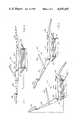
- FIG. 4is a side elevational view of a sit-up type patient support of the present invention, shown in the "sit-up" position; a part of the backrest is broken away to illustrate the top connection of the rear link.
- FIG. 5is a view of the same, shown in a partially reclined position.
- FIG. 6is a view of the same, shown in a fully reclined position.
- FIG. 7is a side elevational view of a "lounge type" patient support of the present invention, shown in a "sit-up" position; a part of the backrest is broken away to illustrate the top connection of the rear link.
- FIG. 8is a view of the same, shown in a partially reclined position.
- FIG. 9is a view of the same, shown in a fully reclined position.
- FIG. 10is a diagramatic, side view representation of the transverse motion reclining linkage of the present invention, shown in a "sit-up" position.
- FIG. 11is a view of the same, shown in a partially reclined position.
- FIG. 12is a view of the same, shown in a fully reclined position.
- a patient support 20 in the prior arthad a base 22 supporting a seat 24 with a legrest 26 pivotally attached to the front end of the seat 24 and a backrest 28 pivotally attached to the back of the seat at a pivot point 30.
- An armrest 32is pivotally attached between the backrest 28 and the seat 24.
- the chair 20is shown in a fully upright position in FIG. 1. After a patient has sat in the chair, motors (not shown) are activated to lift the legrest 26, to recline the backrest 28, and to raise the seat 24, for example through hydraullic cylinders 34.
- Line A in FIG. 1represents the horizontal distance behind the pivot point 30 by which the top of the headrest 36 extends in the fully upright position.
- Line B in FIG. 3represents the horizontal distance behind the pivot point 30 by which the top of the headrest 36 extends in the fully reclined position.
- the ratio (B/A) of backrest extension between the fully reclined and fully upright positions in this prior patient support 20is approximately 2.75 to 1. In other words, almost three times as much space is required behind the chair 20 when it is in the fully reclined position as compared to the fully upright position.
- linkages hereinafter to be describedusually constitute a pair, with one element being located at each side of the chair.
- the assembly of linkages and chair componentsconstitute but a single mechanism. Since the linkages are mirror images at each side of the chair, only one link of each such pair will be described.
- a sit-up type patient support 40is shown in FIGS. 4-6 and has a base 42 supported atop a foldable lifting device 44 (shown broken away at the bottom), which does not form a part of the present invention and may be constructed, for example, as shown in U.S. Pat. Nos. 3,222,032 or 3,472,488.
- the patient support 40has a headrest 46 (such as the headrest shown in U.S. Pat. No. 3,412,538) connected to the top of a backrest 48 which is pivotally connected at a point 50 to the back end of a seat 52.
- the seat 52preferably slopes downwards from front to back at about a 5 degree angle when the patient support is in the fully upright position, as shown in FIG. 4.
- a legrest 54is pivotally connected to the front of the seat 52 at a point 56 via attachment member 58.
- An opening 60is disposed through the attachement member 58 near its middle, and another opening 62 is disposed through attachment member 58 toward its front.
- the back of an armrest 64is pivotally attached to a side of the backrest 48 at a point 66, preferably about eight inches above the pivotal connecting point 50.
- a pivotal connecting member 68depends from the bottom of armrest 64 near its front, preferably about thirteen and one-quarter inches forward of the connecting point 66, for connection to an armrest 1ink 70.
- the armrest linkpreferably about eight inches long, is pivotally connected at its bottom to the side of the seat 52 near its midsection at a point 72, preferably about eleven inches forward of the pivotal connecting point 50.
- a point 72preferably about eleven inches forward of the pivotal connecting point 50.
- an angled extension 74preferably about three inches long.
- a first opening 76is disposed through the extension 74 at about its midsection and another opening 78 is disposed through it near its bottom.
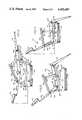
- a four-bar, transverse motion linkage 80(best illustrated in FIGS. 6, 9 and 12) includes: a rear vertical link 82, preferably about eight inches long, pivotally connected between the armrest attachment point 66 and a pivotal connecting member 84 extending slightly upwardly from the back of the base 42; a front vertical link 86, preferably about eleven inches long, pivotally connected at its top to the underside of the seat 52 near the pivotal connecting point 72 for the armrest link 70 and at its bottom, pivotally connected to a pivotal connecting member 88 extending forwardly from the front of the base 42; a horizontal link 90 pivotally connected to the rear vertical link 82 at a point 92 near its midsection and at the front to the forward vertical link 86 at a point 94 near its midsection; and the base 42 itself, which forms a fourth member of the four-bar linkage 80.
- the front connecting member 88is preferably disposed about twenty and one-quarter inches horizontally forward, and about four inches vertically downward of the rear connecting member 84.
- the horizontal link 90has a first portion 91 that is preferably about sixteen and seven-eighths inches long, and an angled second portion 93 that is preferably about four and one-half inches long.
- a leg extension link 96is pivotally connected at its forward end through opening 60 in attachment member 58, to the legrest 54.
- the extension link 96is pivotally connected through an opening 98 (opening 98 is best shown in FIG. 8), disposed somewhat forward of its rear end, to the bottom opening 78 in angled extension 74.
- Another opening 100is disposed through extension 1ink 96 at its rear.
- the links 82, 86, and 90 of said four-bar linkage 80may be constructed as solid, rectangular members having pivotal connecting members at all four corners, or may be constructed as pairs of parallel bar-type links, one member of each pair disposed on each side of the seat.
- the armrest 64, the armrest link 70 and the leg extension link 96may be constructed as single bar-type links on only one side of the seat, or may be used in parallel.
- the linkage system of the present inventioncauses two simultaneous movements.
- a first movementtakes place through the four-bar linkage 80 whereby the entire patient support moves transversely forward, carried on the two vertical links 82 and 86, through the constant spacing of the horizontal link 90.
- a second movementtakes place through a three-bar linkage 102, constituting the armrest 64, the armrest link 70, the angled extension 74, the leg extension link 96, and the attachment member 58, whereby the backrest 48 reclines as the legrest 54 lifts, and vice versa.
- the four-bar linkage 80 and the three-bar linkage 102are interconnected through the backrest 48, the seat 52 and the legrest 54.
- the increasing horizontal distance between the pivotal connecting points 66 and 72, resulting from such movement,thereby imparts motion to the three-bar linkage 102, to move the legrest 54.
- This simultaneous motionprovides a comfortable feeling of support and equilibrium to a patient, since the patient's head does not change height with respect to the floor as much as it did during reclining in previous patient supports.
- a power source(not shown), such as a motor and jack or an hydraulic pump and cylinder, is connected from a central point on the base 42 to the front vertical link 86 at a point near pivotal connecting point 94.
- the power sourcemoves the four-bar linkage 80 forward or rearward, thereby facilitating the simultaneous horizontal and vertical movements of the patient support 40 of the invention.
- Line A in FIG. 4illustrates the horizontal distance between the pivotal connecting member 84 and the top of the headrest 46 when the patient support 40 is in its fully upright position.
- Line B in FIG. 6illustrates the horizontal distance between the pivotal connecting member 84 and the top of the headrest 46 when the patient support 40 is in its fully reclined positon.
- the ratio of line B to line A (B/A)is approximately 1.5 to 1.
- the patient support of the present inventionrequires about one and one-half times the amount of space behind the base 42 for the backrest 48 when it is in the fully reclined position as compared to the fully upright position, representing a significant savings of space over that which was available before the present invention.
- the Lounge Type Patient Support(FIGS. 7, 8 and 9)
- FIGS. 7-9A lounge type embodiment 110 of the patient support of the present invention is illustrated in FIGS. 7-9.
- the patient's legsare already slightly elevated upon initial entry to the patient support. This position is preferred by some dentists.
- the linkage system of the present inventionaccommodates this other embodiment merely by changing the pivotal connecting points at both ends of the leg extension link 96, without detracting from the comfort of the support.
- the rearmost opening 100 (opening 100 is best shown in FIG. 6) in leg extension link 96is pivotally connected to the middle opening 76 in the angled extension 74 of the armrest link 70, as illustrated in FIG. 8.
- the front of leg extension link 96is pivotally connected to the forwardmost opening 62 in the legrest attachment member 58.
- Operation of the lounge type embodiment 110is identical to the sit-up type embodiment 40, and the same desirable ratio (B/A) of approximately 1.5 to 1 is obtained with it.
Landscapes
- Health & Medical Sciences (AREA)
- General Health & Medical Sciences (AREA)
- Dentistry (AREA)
- Life Sciences & Earth Sciences (AREA)
- Animal Behavior & Ethology (AREA)
- Public Health (AREA)
- Veterinary Medicine (AREA)
- Chairs For Special Purposes, Such As Reclining Chairs (AREA)
Abstract
Description
Claims (17)
Priority Applications (1)
| Application Number | Priority Date | Filing Date | Title |
|---|---|---|---|
| US06/399,561US4492407A (en) | 1982-07-19 | 1982-07-19 | Patient support and transverse motion linkage therefor |
Applications Claiming Priority (1)
| Application Number | Priority Date | Filing Date | Title |
|---|---|---|---|
| US06/399,561US4492407A (en) | 1982-07-19 | 1982-07-19 | Patient support and transverse motion linkage therefor |
Publications (1)
| Publication Number | Publication Date |
|---|---|
| US4492407Atrue US4492407A (en) | 1985-01-08 |
Family
ID=23580016
Family Applications (1)
| Application Number | Title | Priority Date | Filing Date |
|---|---|---|---|
| US06/399,561Expired - Fee RelatedUS4492407A (en) | 1982-07-19 | 1982-07-19 | Patient support and transverse motion linkage therefor |
Country Status (1)
| Country | Link |
|---|---|
| US (1) | US4492407A (en) |
Cited By (30)
| Publication number | Priority date | Publication date | Assignee | Title |
|---|---|---|---|---|
| US5086769A (en)* | 1988-09-28 | 1992-02-11 | Whitesun S.P.A. | Tanning chair |
| US5127705A (en)* | 1988-01-27 | 1992-07-07 | Societe Salons Direct Usine | Multifunction and multiposition chair |
| US5547245A (en)* | 1993-05-12 | 1996-08-20 | Knouse; Bobby W. | Recliner chair |
| US5678894A (en)* | 1996-04-08 | 1997-10-21 | Eley; Christopher D. | Dental chair with headrest |
| WO1998035876A1 (en)* | 1997-02-14 | 1998-08-20 | Bar Levav Reuven | Seating plan arrangements for an aircraft cabin |
| US6056363A (en)* | 1997-12-29 | 2000-05-02 | Maddox; Lee W. | Reclining computer chair apparatus |
| US6412870B1 (en)* | 1999-08-04 | 2002-07-02 | Britax Rumbold Limited | Seating unit for a passenger vehicle |
| US20030075962A1 (en)* | 2000-04-19 | 2003-04-24 | Uwe Saltzer | Vehicle seat, especially for aircraft |
| US20040066076A1 (en)* | 2001-08-08 | 2004-04-08 | Jurgen Bauer | Seat |
| US6802564B2 (en)* | 2001-10-12 | 2004-10-12 | Midmark Corporation | Examination and treatment chair |
| US20040232283A1 (en)* | 2001-08-09 | 2004-11-25 | David Ferry | Seating system and a passenger accommodation unit for a vehicle |
| WO2007014564A1 (en) | 2005-08-04 | 2007-02-08 | Heka Dental Aps | A chair or a bed having a seat, a backrest and an armrest as well as use thereof |
| US20080129099A1 (en)* | 2006-12-04 | 2008-06-05 | Cycling & Health Tech Industry R & D Center | Seat reclining mechanism for power wheelchair |
| US20080179934A1 (en)* | 2007-01-29 | 2008-07-31 | Ahearn David J | Chair arm rest system |
| USD583579S1 (en) | 2004-06-18 | 2008-12-30 | Virgin Atlantic Airways Limited | Airplane seating unit |
| US20090021063A1 (en)* | 2007-07-19 | 2009-01-22 | Yoshitoshi Morita | Chair-type massage machine |
| US9782005B2 (en) | 2014-07-25 | 2017-10-10 | Stryker Corporation | Medical support apparatus |
| US9986832B2 (en)* | 2016-06-06 | 2018-06-05 | La-Z-Boy Incorporated | Furniture member with wall-proximity mechanism |
| US10092106B2 (en) | 2015-07-14 | 2018-10-09 | La-Z-Boy Incorporated | Recliner and legrest mechanism for a furniture member |
| US20190184875A1 (en)* | 2017-12-19 | 2019-06-20 | Adient Engineering and IP GmbH | Vehicle seat with armrest |
| US10524574B2 (en) | 2018-05-18 | 2020-01-07 | La-Z-Boy Incorporated | Furniture member with powered wall-proximity mechanism |
| US10524575B2 (en) | 2018-04-16 | 2020-01-07 | La-Z-Boy Incorporated | Furniture member with foldable pawl and ratchet assembly |
| US10537178B2 (en) | 2017-04-07 | 2020-01-21 | La-Z-Boy Incorporated | Furniture member having flexible seatback |
| US10568428B2 (en) | 2017-04-07 | 2020-02-25 | La-Z-Boy Incorporated | Furniture member having flexible seatback |
| US20200156516A1 (en)* | 2018-11-15 | 2020-05-21 | Tachi-S Engineering U.S.A., Incorporated | Sleeper seat for vehicle |
| US10779653B2 (en) | 2016-09-22 | 2020-09-22 | La-Z-Boy Incorporated | Furniture member having legrest mechanism |
| US10820708B2 (en) | 2018-05-18 | 2020-11-03 | La-Z-Boy Incorporated | Furniture member with wall-proximity mechanism and locking trigger |
| US11134778B2 (en) | 2019-05-09 | 2021-10-05 | La-Z-Boy Incorporated | Reclining chaise |
| US11197549B1 (en) | 2020-09-28 | 2021-12-14 | La-Z-Boy Incorporated | Wall-proximity furniture member having sync mechanism |
| US20230068014A1 (en)* | 2021-08-26 | 2023-03-02 | Haining Heli Machinery & Technology Co., Ltd. | Movable chair device and chair assembly |
Citations (9)
| Publication number | Priority date | Publication date | Assignee | Title |
|---|---|---|---|---|
| US477906A (en)* | 1892-06-28 | Reclining-chair | ||
| CA540806A (en)* | 1957-05-14 | M. Vallone Joseph | Convertible reclining chair | |
| FR1247421A (en)* | 1959-10-20 | 1960-12-02 | Convertible seat | |
| US3086815A (en)* | 1959-07-10 | 1963-04-23 | Anton Lorenz | Reclining chair of the multiple movement type |
| US3089741A (en)* | 1960-12-16 | 1963-05-14 | William E Burton | Dental equipment |
| US3536355A (en)* | 1968-06-24 | 1970-10-27 | Gunnar Ingemar Sigvard Osbeck | Surgical chair or the like |
| US3719391A (en)* | 1970-04-17 | 1973-03-06 | V Neri | Chair for use in dentistry |
| US3804460A (en)* | 1972-05-30 | 1974-04-16 | Pelton & Crane Co | Power operated treatment chair |
| DE2459109A1 (en)* | 1973-06-28 | 1976-06-24 | Pontiac Furniture Ind | Chair reclining mechanism - has one back link extending upwards and pivoted to base and back |
- 1982
- 1982-07-19USUS06/399,561patent/US4492407A/ennot_activeExpired - Fee Related
Patent Citations (9)
| Publication number | Priority date | Publication date | Assignee | Title |
|---|---|---|---|---|
| US477906A (en)* | 1892-06-28 | Reclining-chair | ||
| CA540806A (en)* | 1957-05-14 | M. Vallone Joseph | Convertible reclining chair | |
| US3086815A (en)* | 1959-07-10 | 1963-04-23 | Anton Lorenz | Reclining chair of the multiple movement type |
| FR1247421A (en)* | 1959-10-20 | 1960-12-02 | Convertible seat | |
| US3089741A (en)* | 1960-12-16 | 1963-05-14 | William E Burton | Dental equipment |
| US3536355A (en)* | 1968-06-24 | 1970-10-27 | Gunnar Ingemar Sigvard Osbeck | Surgical chair or the like |
| US3719391A (en)* | 1970-04-17 | 1973-03-06 | V Neri | Chair for use in dentistry |
| US3804460A (en)* | 1972-05-30 | 1974-04-16 | Pelton & Crane Co | Power operated treatment chair |
| DE2459109A1 (en)* | 1973-06-28 | 1976-06-24 | Pontiac Furniture Ind | Chair reclining mechanism - has one back link extending upwards and pivoted to base and back |
Cited By (55)
| Publication number | Priority date | Publication date | Assignee | Title |
|---|---|---|---|---|
| US5127705A (en)* | 1988-01-27 | 1992-07-07 | Societe Salons Direct Usine | Multifunction and multiposition chair |
| US5086769A (en)* | 1988-09-28 | 1992-02-11 | Whitesun S.P.A. | Tanning chair |
| US5547245A (en)* | 1993-05-12 | 1996-08-20 | Knouse; Bobby W. | Recliner chair |
| US5678894A (en)* | 1996-04-08 | 1997-10-21 | Eley; Christopher D. | Dental chair with headrest |
| US5865505A (en)* | 1996-04-08 | 1999-02-02 | Eley; Christopher D. | Method of dental treatment |
| WO1998035876A1 (en)* | 1997-02-14 | 1998-08-20 | Bar Levav Reuven | Seating plan arrangements for an aircraft cabin |
| US6056363A (en)* | 1997-12-29 | 2000-05-02 | Maddox; Lee W. | Reclining computer chair apparatus |
| US6412870B1 (en)* | 1999-08-04 | 2002-07-02 | Britax Rumbold Limited | Seating unit for a passenger vehicle |
| US6769739B2 (en)* | 2000-04-19 | 2004-08-03 | Recaro Aircraft Seating Gmbh & Co. | Vehicle seat, especially for aircraft |
| US20030075962A1 (en)* | 2000-04-19 | 2003-04-24 | Uwe Saltzer | Vehicle seat, especially for aircraft |
| US6808234B2 (en)* | 2001-08-08 | 2004-10-26 | Recaro Aircraft Seating Gmbh & Co. | Seat |
| US20040066076A1 (en)* | 2001-08-08 | 2004-04-08 | Jurgen Bauer | Seat |
| US8720821B2 (en) | 2001-08-09 | 2014-05-13 | Virgin Atlantic Airways Limited | Seating system and passenger accommodation unit for a vehicle |
| US20040232283A1 (en)* | 2001-08-09 | 2004-11-25 | David Ferry | Seating system and a passenger accommodation unit for a vehicle |
| US9403597B2 (en) | 2001-08-09 | 2016-08-02 | Virgin Atlantic Airways Limited | Seating system and a passenger accommodation unit for a vehicle |
| US20070069073A1 (en)* | 2001-08-09 | 2007-03-29 | David Ferry | Seating system and a passenger accommodation unit for a vehicle |
| US20070080566A1 (en)* | 2001-08-09 | 2007-04-12 | David Ferry | Seating system and a passenger accommodation unit for a vehicle |
| US8313059B2 (en) | 2001-08-09 | 2012-11-20 | Virgin Atlantic Airways Limited | Seating system and a passenger accommodation unit for a vehicle |
| US7997654B2 (en) | 2001-08-09 | 2011-08-16 | Virgin Atlantic Airways Limited | Seating system and a passenger accommodation unit for a vehicle |
| US7523888B2 (en) | 2001-08-09 | 2009-04-28 | Virgin Atlantic Airways Limited | Seating system and a passenger accommodation unit for a vehicle |
| US7469861B2 (en) | 2001-08-09 | 2008-12-30 | Virgin Atlantic Airways Limited | Seating system and a passenger accommodation unit for a vehicle |
| US7472957B2 (en) | 2001-08-09 | 2009-01-06 | Virgin Atlantic Airways Limited | Seating system and a passenger accommodation unit for a vehicle |
| US6802564B2 (en)* | 2001-10-12 | 2004-10-12 | Midmark Corporation | Examination and treatment chair |
| USD583579S1 (en) | 2004-06-18 | 2008-12-30 | Virgin Atlantic Airways Limited | Airplane seating unit |
| JP2009502373A (en)* | 2005-08-04 | 2009-01-29 | ヘカ・デンタル・アンパルトセルスカブ | Chair, bed with seat, backrest and armrest, and use thereof |
| US20080303329A1 (en)* | 2005-08-04 | 2008-12-11 | Heka Dental Aps | Chair or a Bed Having a Seat, a Backrest and an Armrest as Well as Use Thereof |
| US7618095B2 (en) | 2005-08-04 | 2009-11-17 | Heka Dental A.P.S. | Chair or a bed having a seat, a backrest and an armrest as well as use thereof |
| EA013028B1 (en)* | 2005-08-04 | 2010-02-26 | ХЕКА ДЕНТАЛ АпС | A chair or a bed having a seat, a backrest and an armrest as well as use thereof |
| CN101237792B (en)* | 2005-08-04 | 2011-01-12 | 宜嘉牙科设备公司 | A chair or a bed having a seat, a backrest and an armrest as well as use thereof |
| WO2007014564A1 (en) | 2005-08-04 | 2007-02-08 | Heka Dental Aps | A chair or a bed having a seat, a backrest and an armrest as well as use thereof |
| US7585019B2 (en)* | 2006-12-04 | 2009-09-08 | Cycling & Health Tech Industry R & D Center | Seat reclining mechanism for power wheelchair |
| US20080129099A1 (en)* | 2006-12-04 | 2008-06-05 | Cycling & Health Tech Industry R & D Center | Seat reclining mechanism for power wheelchair |
| US7422288B2 (en) | 2007-01-29 | 2008-09-09 | Ahearn David J | Chair arm rest system |
| US20080179934A1 (en)* | 2007-01-29 | 2008-07-31 | Ahearn David J | Chair arm rest system |
| US20090021063A1 (en)* | 2007-07-19 | 2009-01-22 | Yoshitoshi Morita | Chair-type massage machine |
| US9782005B2 (en) | 2014-07-25 | 2017-10-10 | Stryker Corporation | Medical support apparatus |
| US10595637B2 (en) | 2014-07-25 | 2020-03-24 | Stryker Corporation | Medical support apparatus |
| US10512332B2 (en) | 2015-07-14 | 2019-12-24 | La-Z-Boy Incorporated | Recliner and legrest mechanism for a furniture member |
| US10092106B2 (en) | 2015-07-14 | 2018-10-09 | La-Z-Boy Incorporated | Recliner and legrest mechanism for a furniture member |
| US9986832B2 (en)* | 2016-06-06 | 2018-06-05 | La-Z-Boy Incorporated | Furniture member with wall-proximity mechanism |
| US10779653B2 (en) | 2016-09-22 | 2020-09-22 | La-Z-Boy Incorporated | Furniture member having legrest mechanism |
| US10537178B2 (en) | 2017-04-07 | 2020-01-21 | La-Z-Boy Incorporated | Furniture member having flexible seatback |
| US10568428B2 (en) | 2017-04-07 | 2020-02-25 | La-Z-Boy Incorporated | Furniture member having flexible seatback |
| US10750870B2 (en) | 2017-04-07 | 2020-08-25 | La-Z-Boy Incorporated | Furniture member having flexible seatback |
| US10513208B2 (en)* | 2017-12-19 | 2019-12-24 | Adient Engineering and IP GmbH | Vehicle seat with armrest |
| US20190184875A1 (en)* | 2017-12-19 | 2019-06-20 | Adient Engineering and IP GmbH | Vehicle seat with armrest |
| US10524575B2 (en) | 2018-04-16 | 2020-01-07 | La-Z-Boy Incorporated | Furniture member with foldable pawl and ratchet assembly |
| US10820708B2 (en) | 2018-05-18 | 2020-11-03 | La-Z-Boy Incorporated | Furniture member with wall-proximity mechanism and locking trigger |
| US10524574B2 (en) | 2018-05-18 | 2020-01-07 | La-Z-Boy Incorporated | Furniture member with powered wall-proximity mechanism |
| US20200156516A1 (en)* | 2018-11-15 | 2020-05-21 | Tachi-S Engineering U.S.A., Incorporated | Sleeper seat for vehicle |
| US11134778B2 (en) | 2019-05-09 | 2021-10-05 | La-Z-Boy Incorporated | Reclining chaise |
| US11197549B1 (en) | 2020-09-28 | 2021-12-14 | La-Z-Boy Incorporated | Wall-proximity furniture member having sync mechanism |
| US11622629B2 (en) | 2020-09-28 | 2023-04-11 | La-Z-Boy Incorporated | Wall-proximity furniture member having sync mechanism |
| US20230068014A1 (en)* | 2021-08-26 | 2023-03-02 | Haining Heli Machinery & Technology Co., Ltd. | Movable chair device and chair assembly |
| US11839303B2 (en)* | 2021-08-26 | 2023-12-12 | Haining Heli Machinery & Technology Co., Ltd. | Movable chair device and chair assembly |
Similar Documents
| Publication | Publication Date | Title |
|---|---|---|
| US4492407A (en) | Patient support and transverse motion linkage therefor | |
| US5868467A (en) | Seating furniture component or the like with a coupled backrest and seat adjustment | |
| US4386803A (en) | Motorized reclining chair | |
| US5860701A (en) | Seating furniture component or the like with a coupled backrest and seat adjustment | |
| US4966413A (en) | Articulated relaxation chair | |
| US5772278A (en) | Recliner chair having wall-avoiding linkage arrangement | |
| US3806192A (en) | Chair for dental patients | |
| US3934929A (en) | Adjustable dental chair | |
| US4722566A (en) | Reclining chair frame with adjustable seat and back-rest, in particular for use in dentistry | |
| EP0293136A1 (en) | Improvements in or relating to chairs | |
| CN114009986B (en) | Rocking reclining mechanism for a rocking reclining chair that rocks between the armrests | |
| JP2000107241A (en) | Infusion / dialysis chair | |
| WO1995025452A1 (en) | A chair with a reclinable backrest | |
| CN108294515A (en) | A kind of seat of double acting power drive | |
| JPH02114910A (en) | Reclining arm chair | |
| US3147037A (en) | Head-rest mounting and actuating arrangement | |
| JPS6223479Y2 (en) | ||
| JPS5941876Y2 (en) | seat | |
| CN221511377U (en) | Chair with adjustable mechanism for sitting and standing | |
| CN219109068U (en) | Sofa frame for switching sitting and lying | |
| CN223195760U (en) | A mechanical stretching unit that eliminates the feeling of back rubbing | |
| CN222982737U (en) | Electric chair base and electric chair comprising same | |
| CN221931648U (en) | A kind of auxiliary standing sofa | |
| JP3540762B2 (en) | Reclining wheelchair | |
| JP3225237U (en) | Chair |
Legal Events
| Date | Code | Title | Description |
|---|---|---|---|
| AS | Assignment | Owner name:SYNTEX (U.S.A.) INC.; 3401 HILLVIEW AVE., P.O. BOX Free format text:ASSIGNMENT OF ASSIGNORS INTEREST.;ASSIGNOR:BROADHEAD, JAMES H.;REEL/FRAME:004058/0277 Effective date:19821012 | |
| AS | Assignment | Owner name:DEN-TAL-EZ DENTAL PRODUCTS CORP., 1900 RITTENHOUSE Free format text:ASSIGNMENT OF ASSIGNORS INTEREST.;ASSIGNOR:SYNTEX (U.S.A.) INC.;REEL/FRAME:004671/0857 Effective date:19861010 Owner name:DEN-TAL-EZ DENTAL PRODUCTS CORP., A CORP. OF PA.,P Free format text:ASSIGNMENT OF ASSIGNORS INTEREST;ASSIGNOR:SYNTEX (U.S.A.) INC.;REEL/FRAME:004671/0857 Effective date:19861010 | |
| AS | Assignment | Owner name:MERIDIAN BANK, 5 PENN CENTER PLAZA, PHILADELPHIA, Free format text:SECURITY INTEREST;ASSIGNOR:DEN-TAL-EZ DENTAL PRODUCTS CORP.;REEL/FRAME:004826/0156 Effective date:19861020 Owner name:DEN-TAL-EZ, INC. Free format text:SECURITY INTEREST;ASSIGNOR:DEN-TAL-EZ DENTAL PRODUCTS CORP.;REEL/FRAME:004826/0171 Effective date:19861020 Owner name:MERIDIAN BANK,PENNSYLVANIA Free format text:SECURITY INTEREST;ASSIGNOR:DEN-TAL-EZ DENTAL PRODUCTS CORP.;REEL/FRAME:004826/0156 Effective date:19861020 Owner name:MERIDIAN BANK, PENNSYLVANIA Free format text:SECURITY INTEREST;ASSIGNOR:DEN-TAL-EZ DENTAL PRODUCTS CORP.;REEL/FRAME:004826/0156 Effective date:19861020 | |
| FEPP | Fee payment procedure | Free format text:PAYOR NUMBER ASSIGNED (ORIGINAL EVENT CODE: ASPN); ENTITY STATUS OF PATENT OWNER: LARGE ENTITY | |
| FPAY | Fee payment | Year of fee payment:4 | |
| FEPP | Fee payment procedure | Free format text:PAYER NUMBER DE-ASSIGNED (ORIGINAL EVENT CODE: RMPN); ENTITY STATUS OF PATENT OWNER: LARGE ENTITY Free format text:PAYOR NUMBER ASSIGNED (ORIGINAL EVENT CODE: ASPN); ENTITY STATUS OF PATENT OWNER: LARGE ENTITY | |
| AS | Assignment | Owner name:DENTAL-EZ, INC., PENNSYLVANIA Free format text:ASSIGNMENT OF ASSIGNORS INTEREST AS OF JANUARY 26, 1990;ASSIGNORS:DOMINION BANK OF MARYLAND, N.A.;JEFFERSON BANK;DOMINION BANK, N.A.;REEL/FRAME:005919/0959;SIGNING DATES FROM 19910429 TO 19911112 | |
| FEPP | Fee payment procedure | Free format text:PAYER NUMBER DE-ASSIGNED (ORIGINAL EVENT CODE: RMPN); ENTITY STATUS OF PATENT OWNER: LARGE ENTITY Free format text:PAYOR NUMBER ASSIGNED (ORIGINAL EVENT CODE: ASPN); ENTITY STATUS OF PATENT OWNER: LARGE ENTITY | |
| LAPS | Lapse for failure to pay maintenance fees | ||
| FP | Lapsed due to failure to pay maintenance fee | Effective date:19930110 | |
| STCH | Information on status: patent discontinuation | Free format text:PATENT EXPIRED DUE TO NONPAYMENT OF MAINTENANCE FEES UNDER 37 CFR 1.362 |