US4491439A - Tendon latch - Google Patents
Tendon latchDownload PDFInfo
- Publication number
- US4491439A US4491439AUS06/402,179US40217982AUS4491439AUS 4491439 AUS4491439 AUS 4491439AUS 40217982 AUS40217982 AUS 40217982AUS 4491439 AUS4491439 AUS 4491439A
- Authority
- US
- United States
- Prior art keywords
- latch
- socket
- piston
- tendon
- dog
- Prior art date
- Legal status (The legal status is an assumption and is not a legal conclusion. Google has not performed a legal analysis and makes no representation as to the accuracy of the status listed.)
- Expired - Fee Related
Links
Images
Classifications
- E—FIXED CONSTRUCTIONS
- E02—HYDRAULIC ENGINEERING; FOUNDATIONS; SOIL SHIFTING
- E02D—FOUNDATIONS; EXCAVATIONS; EMBANKMENTS; UNDERGROUND OR UNDERWATER STRUCTURES
- E02D27/00—Foundations as substructures
- E02D27/32—Foundations for special purposes
- E02D27/52—Submerged foundations, i.e. submerged in open water
Definitions
- the present inventiongenerally relates to the connecting of a floating tension leg platform to a subsea anchor base, and more specifically relates to the releasable connecting of tendons extending downwardly from the foating leg platform to sockets on the anchor base.
- One type of floating offshore production platformis the tension leg platform. This type of platform is anchored by tendons running from the platform to an anchor base or foundation on the sea floor. The connecting of the tendons to the foundation often presents difficult problems which are not always carried out by presently available equipment in satisfactory or efficient manner.
- connection between the tendon and foundationis often subject to cycle bending loads as a result of wave and current action on the platform and tendons. This cycle bending stress tends to loosen the connection between the tendons and the foundation. Presently available equipment does not always deal with this cycle bending load in a satisfactory manner.
- Yet another object of this inventionis to connect a tendon from a tension leg platform to a subsea anchor base in a manner resisting cycle bending loads and stresses placed on the connection between the tendons and the anchor base.
- the present inventionin a broad aspect, provides a latch for connecting tendons run from a floating offshore platform to sockets in an anchor base on the sea floor.
- the latchincludes a latch body, having a plurality of dogs disposed therein and urgible outward from the body. The dogs latchingly engage the socket.
- a pistonreleasably disposed within the body above the dogs, moves downwardly when released to urge the dogs outwardly into latching engagement with the socket.
- a triggerreleases the piston when the latch body lands in the socket.
- a series of wedgesdisposed exteriorally on the body, inhibit lateral movement of the latch body relative to the socket in response to any bending stress.
- a plurality of retaining dogsextending outwardly from the movable inwardly into the pistion, latchingly engage the latch body to prevent the downward movement of the piston until the retaining dogs are released.
- the retaining dogsare maintained in engagement with the latch body by a flange resting upon a shoulder in the piston and suspending a shaft downwardly into a through-bore at the bottom of the latch body.
- a removal neckis attached to the piston and allows a tool to run through the tendon to latch upon and pull the piston upwardly to release the latching dogs from engagement with the socket.
- the upward movement of the pistonmoves the retaining dogs upwardly until urged into engagement with the latch body by the flange. The latch may thereafter be removed from the socket.
- the latch bodyincludes a unidirectional valve to displace fluid from adjacent the wedges as both the latch lands in the socket and as water is purged from the latch body.
- the exterior wedgesform two annular tapered rings about the latch body which engage tapered portions in the bore of the socket.
- the wedgesare driven into place either by their own weight or by some other means as the tendons are subjected to cycle bending and prevent the latch from moving relative to the socket.
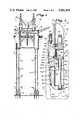
- FIG. 1shows a schematic view of a floating tension leg platform anchored to a subsea anchor base by the tendon latch of the present invention
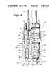
- FIG. 2shows an elevational view, partially in section, of the tendon latch prior to landing in the socket portion of the subsea anchor base
- FIG. 3shows an elevational view, partially in section, of the tendon latch after landing in and latching onto the socket.
- FIG. 1shows an offshore tension leg platform 10 anchored to a series of subsea anchor bases or foundations 21, by a series of tendons 16.
- the tendons 16are interconnected by means of flex/reaction joints 14 to allow the flexure of the tendons in response to wave and current action.
- the tendonsconnect to legs 12 of the platform 10.
- the tension leg platformderives its name from the fact that after the connection is made to the subsea foundation 21, the legs 12 of the platform are made bouyant, by means of air chambers or the like, to place the tendons 16 under tension.
- the connection between the tendons 16 and the foundation 21is made by a tendon latch 40 according to the present invention.
- the tendon latch 40engages a socket 20, as shown in FIG. 2.
- the tendon latch 40includes an upper body 42 attached by bolts 46 or the like to a lower body 44.
- the upper body 42is connected to the tendon 16 by conventional means.
- the lower body 44includes a shoulder 48 having a circumferential seal 50.
- the body 44includes a plurality of openings 44a, each having positioned therein a latch dog 52.
- Three such dogs 52a, b, c,are shown in FIG. 3.
- Each of the dogs 52is provided with a shoulder 52' which engages a corresponding shoulder 44b in the openings 44a.
- Each of the dogs 52ais also provided with a cam surface 52" on its upper rear surface.
- the lowermost portion of the lower body 44is provided with an opening 54 having a plurality of seals 98 positioned therein. It is into this opening 54 that a trigger pin 22 on the socket 20 enters to cause engagement between the latch 40 and the socket 20.
- the upper wedge ring 80is maintained on the outside of the latch body 44 by means of an floating upper collar 82 and an upper annular ring 83.
- the lower wedge ring 84is maintained in position on the wedge body 44 by means of a lower floating collar 86 and a lower annular ring 87.
- a generally cylindrical and hollow piston 64having a cam 64' disposed adjacent the cam surface 52" on the latch dogs 52.
- the piston 64is provided with a plurality of openings 65 into which are inserted a series of retaining dogs 60, with each of the retaining dogs 60 having a shoulder 60' which engages a comparable shoulder 64" on the piston.
- Each of the retaining dogs 60also includes a cam surface 60" on its upper back side. The retaining dogs 60 engage an annular recess 100 in the lower body 44.
- Threadingly engaging the upper portion of the piston 64is a flanged neck 68 provided with an annular groove 70 to engage a tool 19 inserted into the tendon 16 to effect removal of the latch as described hereinbelow.
- a collar 66 threaded onto the lower body 44 above the piston 64facilitates disassembly of the latch.
- a disk or flange 62Disposed interiorally within the piston 64 is a disk or flange 62 having a cam surface 62'.
- the flange 62rests on a shoulder 64a in the piston.
- the flange 62is attached to or formed integrally with a shaft 56, which is suspended downwardly into the opening 54 in the lower body 44.
- the socket 20 into which the latch 40 is landedhas a generally circular body with a trigger pin 22 projecting upwardly therefrom.
- the bore of the socket 20is provided with an upper conical surface 26 and a lower conical surface 28 which respectively engage the upper and lower wedge rings 80 and 84 as described below.
- the bore of the socket 20is also provided with an annular recess 30 which engages the latching dogs 52 when the latch 40 is latched to the socket.
- the socket bore 20is also provided with a plurality of vents 24 communicating with the sea to allow water to be pushed out of the socket 20 by the latch 40 as it enters the socket.
- the vents 24are also used in the purging of water from the latch body after landing in the socket and in the forcing of oil through the latch body for corrosion protection, as described below.
- a passage 92 in the lower latch body 44connects the area adjacent the lower wedge ring 84 and the one-way valve 90.
- FIG. 2shows the arrangement of components in the latch 40 as the latch 40 enters the socket 20.
- the retaining dogs 60engage the annular recess 100 in the latch body 44 to prevent downward movement of the piston 64.
- the retaining dogs 60are urged into the annular recess 100 by the flange 62.
- the flange 62with the accompanying shaft 56, form a trigger mechanism which maintains the piston 64 releasably disposed above the latching dogs 52 until the trigger pin 22 enters the through-bore 54 at the bottom of the lower body 44 when the latch 40 is landing in the socket 20. Sealing engagement between the trigger pin 22 and the latch body 44, after the trigger pin enters the through-bore 54, is provided by means of the seal rings 98 in the through-bore 54.
- the downward movement of the piston 64brings the cam 64' on the piston into engagement with the cam surface 52" on the latching dogs 52 to urge the latching dogs 52 out of the lower latch body 44 and into engagement with the annular recess 30 in the socket bore 20.
- the outward movement of the latching dogs 52continues until the shoulders 52' on the dogs contact the shoulders 44b on the lower body 44.
- the tendon latch 40is latched onto the socket 20, as the final position of the piston 64, as shown in FIG. 3, prevents inward movement of the dogs 52.
- the landing of the latch body 44 in the socket 20causes water to be displaced through the vents 24 to the sea.
- Water adjacent the lower wedge ring 84is exhausted through the passage 92 and the one-way valve 90 to the lower portion of the latch body 44, where it is then forced through the vents 24 to the sea.
- oilmay be passed into the latch body 44 from the tendon 16 and thereafter forced out of the body 44 by air in a manner similar to the purge of the water described above in order to provide corrosion protection.
- the purge of the oilwill cause it to coat the exterior of the latch body 44 and the interior of the socket 20 to inhibit corrosion.
- Retrieval of the latch 40is done by running a tool 19 through the tendon 16 to connect to the annular groove 70 on the flanged neck 68 attached to the piston.
- the piston 64is lifted by the tool 19 until the latching dogs 52 are released, thus releasing the latch itself. Thereafter, the tendon 16 and latch 40 are lifted away from the socket 20. More specifically, the lifting of the piston 64 removes the cam 64' from contact with the cam surface 52" on the latching dogs 52. Thus, the latching dogs 52 are free to move inwardly.
- the present inventionnot only provides a novel apparatus, but also provides a novel method for latching the tendons 16 run from the offshore floating platform 10 to the socket 20.
- the methodincludes running the tendon latch 40 into the socket 20, while maintaining the piston 64 releasably disposed for downward movement in the latch above the latching dogs 52.
- the pistonis maintained in this orientation by the retaining dogs 60, which are urged into the annular recess 100 by the disk 62 attached to the shaft 56.
- the retaining dogs 60are no longer maintained in engagement with the latch body 44 and thus allow the piston 64 to move downwardly.
- the downward movement of the piston 64is utilized to cam the latching dogs 52 into engagement with the annular recess 30 in the socket 20.
- the final position of the piston 64prevents the latching dogs 52 from moving out of engagement with the socket 20.
Landscapes
- Engineering & Computer Science (AREA)
- Life Sciences & Earth Sciences (AREA)
- General Life Sciences & Earth Sciences (AREA)
- Mining & Mineral Resources (AREA)
- Paleontology (AREA)
- Civil Engineering (AREA)
- General Engineering & Computer Science (AREA)
- Structural Engineering (AREA)
- Earth Drilling (AREA)
Abstract
Description
The present invention generally relates to the connecting of a floating tension leg platform to a subsea anchor base, and more specifically relates to the releasable connecting of tendons extending downwardly from the foating leg platform to sockets on the anchor base.
One type of floating offshore production platform is the tension leg platform. This type of platform is anchored by tendons running from the platform to an anchor base or foundation on the sea floor. The connecting of the tendons to the foundation often presents difficult problems which are not always carried out by presently available equipment in satisfactory or efficient manner.
Additionally, the connection between the tendon and foundation is often subject to cycle bending loads as a result of wave and current action on the platform and tendons. This cycle bending stress tends to loosen the connection between the tendons and the foundation. Presently available equipment does not always deal with this cycle bending load in a satisfactory manner.
Furthermore, it is desirable to be able to quickly release the tendons from the anchor base to facilitate movement of the tension leg platform. Presently available equipment often does not provide for an efficient manner of rapidly releasing the tendons from the subsea anchor base.
Accordingly, it is the principle object of the pesent invention to quickly and efficiently connect tendons from a tension leg platform to a subsea anchor base.
It is a further object of this invention to quickly and efficiently disconnect the tendons from the anchor base.
It is another object of this invention to connect and disconnect tendons from a tension leg platform to a subsea anchor base with a mechanically simple arrangement.
Yet another object of this invention is to connect a tendon from a tension leg platform to a subsea anchor base in a manner resisting cycle bending loads and stresses placed on the connection between the tendons and the anchor base.
The present invention, in a broad aspect, provides a latch for connecting tendons run from a floating offshore platform to sockets in an anchor base on the sea floor. The latch includes a latch body, having a plurality of dogs disposed therein and urgible outward from the body. The dogs latchingly engage the socket. A piston, releasably disposed within the body above the dogs, moves downwardly when released to urge the dogs outwardly into latching engagement with the socket. A trigger releases the piston when the latch body lands in the socket. A series of wedges, disposed exteriorally on the body, inhibit lateral movement of the latch body relative to the socket in response to any bending stress.
In accordance with one feature of the invention, a plurality of retaining dogs, extending outwardly from the movable inwardly into the pistion, latchingly engage the latch body to prevent the downward movement of the piston until the retaining dogs are released. The retaining dogs are maintained in engagement with the latch body by a flange resting upon a shoulder in the piston and suspending a shaft downwardly into a through-bore at the bottom of the latch body. When the latch lands in the socket, a trigger in the bottom of the socket makes contact with the shaft and urges the shaft and the flange upwardly. The upward movement of the flange releases the retaining dogs from engagement with the latch body, thereby allowing the piston to move downwardly to urge the latching dogs into engagement with the sockets.
In accordance with another feature of the present invention, a removal neck is attached to the piston and allows a tool to run through the tendon to latch upon and pull the piston upwardly to release the latching dogs from engagement with the socket. The upward movement of the piston moves the retaining dogs upwardly until urged into engagement with the latch body by the flange. The latch may thereafter be removed from the socket.
In accordance with another feature of the invention, the latch body includes a unidirectional valve to displace fluid from adjacent the wedges as both the latch lands in the socket and as water is purged from the latch body.
In accordance with yet another feature of the invention, the exterior wedges form two annular tapered rings about the latch body which engage tapered portions in the bore of the socket. The wedges are driven into place either by their own weight or by some other means as the tendons are subjected to cycle bending and prevent the latch from moving relative to the socket.
Other object, features, and advantages of the present invention will become apparent from a consideration of the following detailed description and the accompanying drawings.
FIG. 1 shows a schematic view of a floating tension leg platform anchored to a subsea anchor base by the tendon latch of the present invention;
FIG. 2 shows an elevational view, partially in section, of the tendon latch prior to landing in the socket portion of the subsea anchor base; and
FIG. 3 shows an elevational view, partially in section, of the tendon latch after landing in and latching onto the socket.
Referring more particularly to the drawings, FIG. 1 shows an offshoretension leg platform 10 anchored to a series of subsea anchor bases orfoundations 21, by a series oftendons 16. Thetendons 16 are interconnected by means of flex/reaction joints 14 to allow the flexure of the tendons in response to wave and current action. The tendons connect tolegs 12 of theplatform 10.
The tension leg platform derives its name from the fact that after the connection is made to thesubsea foundation 21, thelegs 12 of the platform are made bouyant, by means of air chambers or the like, to place thetendons 16 under tension.
The connection between thetendons 16 and thefoundation 21 is made by atendon latch 40 according to the present invention. Thetendon latch 40 engages asocket 20, as shown in FIG. 2. As all of thetendon latches 40 in FIG. 1 are identical, only one will be discussed in detail for purposes of this invention.
Referring to FIG. 2, thetendon latch 40 includes anupper body 42 attached bybolts 46 or the like to alower body 44. Theupper body 42 is connected to thetendon 16 by conventional means. Thelower body 44 includes ashoulder 48 having acircumferential seal 50. Thebody 44 includes a plurality ofopenings 44a, each having positioned therein alatch dog 52. Threesuch dogs 52a, b, c, are shown in FIG. 3. Each of thedogs 52 is provided with a shoulder 52' which engages acorresponding shoulder 44b in theopenings 44a. Each of thedogs 52a is also provided with acam surface 52" on its upper rear surface.
The lowermost portion of thelower body 44 is provided with an opening 54 having a plurality of seals 98 positioned therein. It is into this opening 54 that atrigger pin 22 on thesocket 20 enters to cause engagement between thelatch 40 and thesocket 20.
Disposed about the exterior of thelower body 44 are two pluralities of wedges, 80 and 84, forming two segmented wedge rings. Theupper wedge ring 80 is maintained on the outside of thelatch body 44 by means of an floatingupper collar 82 and an upperannular ring 83. Thelower wedge ring 84 is maintained in position on thewedge body 44 by means of a lowerfloating collar 86 and a lowerannular ring 87. Thesewedge rings socket 20 to resist lateral movement of thelatch 40 in thesocket 20 in response to cycle bending loads.
Disposed interiorally in thelower latch body 44 is a generally cylindrical andhollow piston 64 having a cam 64' disposed adjacent thecam surface 52" on thelatch dogs 52. Thepiston 64 is provided with a plurality of openings 65 into which are inserted a series of retainingdogs 60, with each of the retainingdogs 60 having a shoulder 60' which engages acomparable shoulder 64" on the piston. Each of the retainingdogs 60 also includes acam surface 60" on its upper back side. The retainingdogs 60 engage anannular recess 100 in thelower body 44.
Threadingly engaging the upper portion of thepiston 64 is aflanged neck 68 provided with anannular groove 70 to engage a tool 19 inserted into thetendon 16 to effect removal of the latch as described hereinbelow. Acollar 66 threaded onto thelower body 44 above thepiston 64 facilitates disassembly of the latch.
Disposed interiorally within thepiston 64 is a disk orflange 62 having a cam surface 62'. Theflange 62 rests on ashoulder 64a in the piston. Theflange 62 is attached to or formed integrally with ashaft 56, which is suspended downwardly into theopening 54 in thelower body 44.
Thesocket 20 into which thelatch 40 is landed has a generally circular body with atrigger pin 22 projecting upwardly therefrom. The bore of thesocket 20 is provided with an upperconical surface 26 and a lowerconical surface 28 which respectively engage the upper and lower wedge rings 80 and 84 as described below. The bore of thesocket 20 is also provided with anannular recess 30 which engages the latchingdogs 52 when thelatch 40 is latched to the socket.
The socket bore 20 is also provided with a plurality ofvents 24 communicating with the sea to allow water to be pushed out of thesocket 20 by thelatch 40 as it enters the socket. Thevents 24 are also used in the purging of water from the latch body after landing in the socket and in the forcing of oil through the latch body for corrosion protection, as described below. Cooperating with thevents 24 in a one-way valve 90, as known in the art, in thelower latch body 44 through which fluid adjacent thelower wedge ring 84 is passed. Apassage 92 in thelower latch body 44 connects the area adjacent thelower wedge ring 84 and the one-way valve 90.
FIG. 2 shows the arrangement of components in thelatch 40 as thelatch 40 enters thesocket 20. As shown therein, the retainingdogs 60 engage theannular recess 100 in thelatch body 44 to prevent downward movement of thepiston 64. The retainingdogs 60 are urged into theannular recess 100 by theflange 62. Theflange 62, with the accompanyingshaft 56, form a trigger mechanism which maintains thepiston 64 releasably disposed above the latchingdogs 52 until thetrigger pin 22 enters the through-bore 54 at the bottom of thelower body 44 when thelatch 40 is landing in thesocket 20. Sealing engagement between thetrigger pin 22 and thelatch body 44, after the trigger pin enters the through-bore 54, is provided by means of the seal rings 98 in the through-bore 54.
The entry of thetrigger pin 22 in thebore 54 stops the downward movement of theshaft 56 as soon as contact is made therewith. However, thelatch body 44 continues to move downwardly into thesocket 20 until it is completely landed therein, as shown in FIG. 3. The preventing of further downward movement of theshaft 56 by thetrigger pin 22 results in theflange 62 coming out of engagement with the retainingdogs 60, as shown in FIG. 3. Accordingly, the weight of thepiston 64 pushes the retainingdogs 60 back into the piston body until the shoulders 60' on thedogs 60 abut theshoulders 64" on thepiston body 64. Furthermore, the downward movement of thepiston 64 brings the cam 64' on the piston into engagement with thecam surface 52" on the latchingdogs 52 to urge the latchingdogs 52 out of thelower latch body 44 and into engagement with theannular recess 30 in the socket bore 20. The outward movement of the latchingdogs 52 continues until the shoulders 52' on the dogs contact theshoulders 44b on thelower body 44. As a result, thetendon latch 40 is latched onto thesocket 20, as the final position of thepiston 64, as shown in FIG. 3, prevents inward movement of thedogs 52.
The landing of thelatch body 44 in thesocket 20 causes water to be displaced through thevents 24 to the sea. Water adjacent thelower wedge ring 84 is exhausted through thepassage 92 and the one-way valve 90 to the lower portion of thelatch body 44, where it is then forced through thevents 24 to the sea.
After thelatch body 44 lands in thesocket 30, water is purged from thelatch body 44 by forcing air through thetendon 16 to which the latch is attached and into thelatch body 44. The air pushes the water through theopenings 44a in thelatch body 44 and into thesocket 20. The water moves past thelower wedge ring 84 and through the one way valve 90 for passage to the sea through thevents 24.
After the water purge, oil may be passed into thelatch body 44 from thetendon 16 and thereafter forced out of thebody 44 by air in a manner similar to the purge of the water described above in order to provide corrosion protection. The purge of the oil will cause it to coat the exterior of thelatch body 44 and the interior of thesocket 20 to inhibit corrosion.
Lateral movement of thelatch body 44 in thesocket 20 is prevented by means of the upper and lower wedge rings 80 and 84. These gravity-basedwedges conical surfaces socket 20 either by their own weight or by external means. A cycle bending load applied to thetendon latch 40 thereafter moves the wedges in the wedge rings 80 and 84 into tighter engagement with thesocket 20 and lateral movement of thelatch 40 relative to thesocket 20 is prevented.
Retrieval of thelatch 40, as mentioned, is done by running a tool 19 through thetendon 16 to connect to theannular groove 70 on theflanged neck 68 attached to the piston. Thepiston 64 is lifted by the tool 19 until the latchingdogs 52 are released, thus releasing the latch itself. Thereafter, thetendon 16 and latch 40 are lifted away from thesocket 20. More specifically, the lifting of thepiston 64 removes the cam 64' from contact with thecam surface 52" on the latchingdogs 52. Thus, the latchingdogs 52 are free to move inwardly. Continued lifting of thepiston 64 brings the cam 62' on theflange 62 into contact with thecam surface 60" on the retainingdogs 60 to urge thedogs 60 back into theannular recess 100 on thelatch body 44 and "reset" the latch, whereupon theflange 62 again rests upon theshoulder 64a on thepiston 64. At this point the running tool 19 is removed and thelatch 40 is lifted from thesocket 20 by itstendon 16. After all the tendon latches 40 have been released, theplatform 10 is free to move.
As seen from the foregoing, the present invention not only provides a novel apparatus, but also provides a novel method for latching thetendons 16 run from the offshore floatingplatform 10 to thesocket 20. The method includes running thetendon latch 40 into thesocket 20, while maintaining thepiston 64 releasably disposed for downward movement in the latch above the latchingdogs 52. The piston is maintained in this orientation by the retainingdogs 60, which are urged into theannular recess 100 by thedisk 62 attached to theshaft 56. When the shaft and disk are moved upwardly by thetrigger pin 22 in thesocket 20 and thelatch 40 lands in thesocket 20, the retainingdogs 60 are no longer maintained in engagement with thelatch body 44 and thus allow thepiston 64 to move downwardly. The downward movement of thepiston 64 is utilized to cam the latchingdogs 52 into engagement with theannular recess 30 in thesocket 20. The final position of thepiston 64 prevents the latchingdogs 52 from moving out of engagement with thesocket 20.
In the foregoing description of the present invention, a preferred embodiment of the invention has been disclosed and discussed in detail. It is to be understood that other mechanical and design variations are within the scope of the present invention. Accordingly, the invention is not limited to the particular embodiment which has been disclosed and discussed in detail herein.
Claims (18)
1. A latch for connecting a tendon run from an offshore platform to a socket in a foundation on the sea floor comprising:
a latch body;
dog means disposed within the urgible outwardly from said body to latchingly engage said socket;
piston means, releasably disposed within said body above said dog means, for moving when released to urge said dog means outwardly from said body into latching engagement with said socket; and
trigger means for releasing said piston means when said latch body lands in said socket.
2. A latch as defined in claim 3, wherein said latch further comprises:
wedge means, disposed exteriorally on said body, and axially spaced apart for wedging between said socket and said body, for inhibiting lateral movement of said body relative to said socket.
3. A latch as defined in claim 3, wherein:
said socket includes trigger pin means for activating said trigger means when said latch body lands in said socket, and annular recess means for receiving said dog means to latchingly engage said latch body to said socket; and
said latch body includes internal recess means into which said piston means is latched until released by said trigger means, and through-bore means for receiving said trigger pin means into said latch body when said latch body lands on said socket.
4. A latch as defined in claim 1, wherein:
said dog means includes cam surface means for receiving said piston means when said piston means is released.
5. A latch as defined in claim 4, wherein:
said piston means includes cam means for engaging said cam surface means when said piston means is released to urge said dog means outwardly from said body into latching engagement with said socket, and support means for supporting said trigger means.
6. A latch as defined in claim 1, wherein said latch further comprises:
retaining dog means, disposed in said piston means in latching engagement with said latch body, for maintaining said piston means latched to said latch body until said piston means is released, whereupon said retaining dog means move inwardly to allow said piston means to move downwardly to engage said dog means to urge said dog means into engagement with said socket means to latch said latch body to said socket.
7. A latch as defined in claim 6, wherein said trigger means comprises:
shaft means, extending through said piston and exposed to said socket, for contacting with said trigger pin means when said latch body lands in said socket, said contact moving said shaft means upwardly; and
disk means, formed on said shaft means and resting upon said piston means, for engaging said retaining dog means to maintain said retaining dog means urged outwardly from said piston means and in latching engagement with said latch body until said shaft means contacts said trigger pin means, whereupon said shaft means moves said disk means off said piston means and out of engagement with said retaining dog means, thereby releasing said piston means to move downwardly into contact with said dog means to latch said latch body to said socket.
8. A latch as defined in claim 2, wherein:
said socket includes a plurality of tapered portions of reduced diameter in the bore of said socket for engagement with said wedge means; and
said wedge means includes a plurality of wedges disposed externally about said latch body to form a plurality of segmented tapered rings, said rings engaging said tapered portions in said socket to prevent lateral movement of said latch body in said socket.
9. A latch as defined in claim 2, wherein:
said socket includes vent means, communicating with the sea, for allowing displacement of fluid from said socket; and
said latch further includes one-way valve means, disposed adjacent said wedge means, for directing fluid adjacent from said wedge means to said vent means.
10. An latch as defined in claim 1, wherein said latch further includes:
neck means, attached to said piston means, for releasing said latch from said socket, said neck means adapted to engage a tool run through said tendon, said tool lifting said piston means from engagement with said dog means to allow said latch to be lifted from said socket.
11. A latch for attaching a tendon run from a floating platform to a tubular socket on a subsea foundation, the bore of said socket having a plurality of annular tapered portions of reduced diameter, and said socket including trigger pin means for activating said latch, said latch comprising:
a latch body connected to said tendon and including a through-bore for receiving said trigger pin means;
latching dog means, extending through and movable outwardly from said body, for engaging said socket;
piston means, releasably disposed in the bore of said latch body, for moving downwardly when released to urge said latching dog means outwardly from said latch body;
retaining dog means, extending outwardly from and movable inwardly into said piston means, for latchingly engaging said latch body to prevent said downward movement of said pistion means until said retaining dog means are released;
trigger means, disposed in said body, for maintaining said retaining dog means biased outwardly to latchingly engage said latch body until said latch body lands in said socket, whereupon said trigger means releases said retaining dog means to allow said piston means to move downwardly to urge said latching dog means into engagement with said socket; and
a plurality of wedges forming a plurality of segmented annular rings disposed about the exterior of said latch body, said tapered rings disposed to engage said annular portions of reduced diameter in said socket after said latch body has landed therein, whereby movement of said latch body in said socket is inhibited when a cycle bending load is applied to said tendon.
12. An apparatus as defined in claim 11, wherein said apparatus further includes:
removal neck means, attached to said piston means, for allowing a tool run through said tendon to latch upon and pull said piston means upwardly to release said latching dog means from engagement with said socket.
13. An apparatus as defined in claim 11, wherein:
said socket includes vent means, communicating with the sea, for allowing displacement of fluid from said socket; and
said latch body includes unidirectional valve means for displacing fluid from an area adjacent said wedges to said vent means.
14. A method of attaching a tendon run from an offshore floating platform to a socket incorporating trigger means in a foundation on the sea floor, comprising:
running a latch attached to said tendon into said socket;
maintaining a piston releasably disposed for movement in said latch;
establishing contact between said latch and said trigger means to release said piston for movement; and
utilizing said piston movement to move a plurality of dogs in said latch into engagement with said socket.
15. A method of inhibiting lateral movement of a latch attached to a tendon run from an offshore platform to a socket on the sea floor due to bending movement of the tendon comprising:
providing said latch with axially spaced apart exteriorally disposed wedge means; and
utilizing the lateral movement of said latch in said socket after landing in said socket to allow each of said wedge means to be driven by the force of its own weight into wedging engagement between said latch and said socket, whereupon further lateral movement of said latch relative to said socket is inhibited.
16. A method of attaching a tendon run from an offshore floating platform to a socket having an upwardly disposed trigger pin in a foundation on the sea floor, said method comprising:
running a latch from said tendon into said socket;
maintaining a piston releasably disposed for downward movement in said latch by means of dogs extending through said piston into engagement with the interior of said latch;
maintaining said dogs in engagement with said latch by a disk member attached to a shaft extending downwardly through said latch;
moving said shaft and said disk upwardly by said trigger pin when said latch is landed in said socket, whereupon said dogs are no longer maintained in engagement with said latch and said piston is released to move downwardly; and
utilizing said downward movement of said piston to move a plurality of latching dogs outwardly from said latch body into latching engagement with said socket.
17. A latch assembly for attaching a tendon run from a floating platform to a subsea foundation, comprising:
a tubular socket on the foundation, the bore of said socket having a plurality of axially spaced apart annular tapered portions of reduced diameter;
trigger pin means in said socket for activating said latch;
a latch body connected to said tendon and including a through-bore for receiving said trigger pin means;
latching dog means, extending through and movable outwardly from said body, for engaging said socket;
piston means, releasably disposed in the bore of said latch body, for moving downwardly when released to urge said latching dog means outwardly from said latch body;
retaining dog means, extending outwardly from and movable inwardly into said piston means, for latchingly engaging said latch body to prevent said downward movement of said piston means until said retaining dog means are released;
trigger means, disposed in said body, for maintaining said retaining dog means biased outwardly to latchingly engage said latch body until said latch body lands in said socket, whereupon said trigger means releases said retaining dog means to allow said piston means to move downwardly to urge said latching dog means into engagement with said socket.
18. A latch assembly for attaching a tendon run from a floating platform to a subsea foundation, comprising:
a tubular socket on the foundation having a pair of axially spaced apart annular tapered portions of reduced diameter;
a latch body connected to said tendon for reception in the socket;
latching dog means movably carried on said body for releasably engaging said socket to secure said body to said socket;
means, triggered by the landing of said body in said socket, for effecting latching of said latching dog means;
a plurality of wedges forming a pair of axially spaced apart annular rings disposed about the exterior of said latch body, said tapered rings disposed to engage said annular tapered portions in said socket after said latch body has landed therein, to inhibit movement of said latch body when a bending load is applied to said tendon.
Priority Applications (2)
| Application Number | Priority Date | Filing Date | Title |
|---|---|---|---|
| US06/402,179US4491439A (en) | 1982-07-26 | 1982-07-26 | Tendon latch |
| CA000421451ACA1202189A (en) | 1982-07-26 | 1983-02-11 | Tendon latch |
Applications Claiming Priority (1)
| Application Number | Priority Date | Filing Date | Title |
|---|---|---|---|
| US06/402,179US4491439A (en) | 1982-07-26 | 1982-07-26 | Tendon latch |
Publications (1)
| Publication Number | Publication Date |
|---|---|
| US4491439Atrue US4491439A (en) | 1985-01-01 |
Family
ID=23590853
Family Applications (1)
| Application Number | Title | Priority Date | Filing Date |
|---|---|---|---|
| US06/402,179Expired - Fee RelatedUS4491439A (en) | 1982-07-26 | 1982-07-26 | Tendon latch |
Country Status (2)
| Country | Link |
|---|---|
| US (1) | US4491439A (en) |
| CA (1) | CA1202189A (en) |
Cited By (12)
| Publication number | Priority date | Publication date | Assignee | Title |
|---|---|---|---|---|
| US4664558A (en)* | 1984-07-09 | 1987-05-12 | Agip S.P.A. | Reversible mechanical coupling for tensional anchorages |
| US4780026A (en)* | 1987-03-31 | 1988-10-25 | Exxon Production Research Company | Tension leg platform and installation method therefor |
| US4797036A (en)* | 1987-01-12 | 1989-01-10 | Brown & Root Vickers Technology | Marine tether anchoring device |
| US4828035A (en)* | 1988-09-21 | 1989-05-09 | Exxon Production Research Company | Subsea guidepost latch mechanism and method for using |
| US4848970A (en)* | 1987-10-06 | 1989-07-18 | Conoco Inc. | Mooring apparatus and method of installation for deep water tension leg platform |
| US4881852A (en)* | 1988-01-22 | 1989-11-21 | Exxon Production Research Company | Method and apparatus for tensioning the tethers of a tension leg platform |
| US4892445A (en)* | 1987-04-29 | 1990-01-09 | The United States Of America As Represented By The Secretary Of The Navy | Man portable shallow water structure |
| US4927295A (en)* | 1988-09-09 | 1990-05-22 | Cameron Iron Works Usa, Inc. | Retrievable guide post system |
| US4984527A (en)* | 1985-05-17 | 1991-01-15 | Institut Francais Du Petrole | Device for the remote assembly of two members |
| US20070292213A1 (en)* | 2006-06-16 | 2007-12-20 | Vetco Gray Inc. | System, method, and apparatus for locking down tendon or riser moorings |
| US20090097926A1 (en)* | 2006-04-07 | 2009-04-16 | Paulsen Ole K | Connector Assembly for an Off Shore Riser |
| US20090290939A1 (en)* | 2008-05-21 | 2009-11-26 | Edward Sean Large | Method and apparatus for restraining a tendon top connector in reverse loading conditions |
Citations (10)
| Publication number | Priority date | Publication date | Assignee | Title |
|---|---|---|---|---|
| US3222088A (en)* | 1961-10-30 | 1965-12-07 | Shell Oil Co | Wellhead connector with diagonally directed latches |
| US3223164A (en)* | 1962-11-09 | 1965-12-14 | Lloyd G Otteman | Method of actuating fluid pressure operated mechanism of underwater well installation |
| US3321217A (en)* | 1965-08-02 | 1967-05-23 | Ventura Tool Company | Coupling apparatus for well heads and the like |
| US3452815A (en)* | 1967-07-31 | 1969-07-01 | Regan Forge & Eng Co | Latching mechanism |
| US3492027A (en)* | 1968-03-11 | 1970-01-27 | Rockwell Mfg Co | Remote connection release |
| US3675713A (en)* | 1970-03-30 | 1972-07-11 | Regan Forge & Eng Co | Method and apparatus for separating subsea well conduit couplings from a remote floating vessel |
| US3851708A (en)* | 1972-11-17 | 1974-12-03 | Dresser Ind | Well packer and retriever |
| US4086776A (en)* | 1977-04-11 | 1978-05-02 | Compagnie Francaise Des Petroles | Lock means for a tension line |
| US4333528A (en)* | 1980-10-02 | 1982-06-08 | Hughes Tool Company | Seal assembly releasing tool |
| US4405016A (en)* | 1980-12-18 | 1983-09-20 | Smith International, Inc. | Underwater Christmas tree cap and lockdown apparatus |
- 1982
- 1982-07-26USUS06/402,179patent/US4491439A/ennot_activeExpired - Fee Related
- 1983
- 1983-02-11CACA000421451Apatent/CA1202189A/ennot_activeExpired
Patent Citations (10)
| Publication number | Priority date | Publication date | Assignee | Title |
|---|---|---|---|---|
| US3222088A (en)* | 1961-10-30 | 1965-12-07 | Shell Oil Co | Wellhead connector with diagonally directed latches |
| US3223164A (en)* | 1962-11-09 | 1965-12-14 | Lloyd G Otteman | Method of actuating fluid pressure operated mechanism of underwater well installation |
| US3321217A (en)* | 1965-08-02 | 1967-05-23 | Ventura Tool Company | Coupling apparatus for well heads and the like |
| US3452815A (en)* | 1967-07-31 | 1969-07-01 | Regan Forge & Eng Co | Latching mechanism |
| US3492027A (en)* | 1968-03-11 | 1970-01-27 | Rockwell Mfg Co | Remote connection release |
| US3675713A (en)* | 1970-03-30 | 1972-07-11 | Regan Forge & Eng Co | Method and apparatus for separating subsea well conduit couplings from a remote floating vessel |
| US3851708A (en)* | 1972-11-17 | 1974-12-03 | Dresser Ind | Well packer and retriever |
| US4086776A (en)* | 1977-04-11 | 1978-05-02 | Compagnie Francaise Des Petroles | Lock means for a tension line |
| US4333528A (en)* | 1980-10-02 | 1982-06-08 | Hughes Tool Company | Seal assembly releasing tool |
| US4405016A (en)* | 1980-12-18 | 1983-09-20 | Smith International, Inc. | Underwater Christmas tree cap and lockdown apparatus |
Cited By (16)
| Publication number | Priority date | Publication date | Assignee | Title |
|---|---|---|---|---|
| AU577131B2 (en)* | 1984-07-09 | 1988-09-15 | Agip S.P.A. | Mechanical coupling |
| US4664558A (en)* | 1984-07-09 | 1987-05-12 | Agip S.P.A. | Reversible mechanical coupling for tensional anchorages |
| US4984527A (en)* | 1985-05-17 | 1991-01-15 | Institut Francais Du Petrole | Device for the remote assembly of two members |
| US4797036A (en)* | 1987-01-12 | 1989-01-10 | Brown & Root Vickers Technology | Marine tether anchoring device |
| US4780026A (en)* | 1987-03-31 | 1988-10-25 | Exxon Production Research Company | Tension leg platform and installation method therefor |
| US4892445A (en)* | 1987-04-29 | 1990-01-09 | The United States Of America As Represented By The Secretary Of The Navy | Man portable shallow water structure |
| US4848970A (en)* | 1987-10-06 | 1989-07-18 | Conoco Inc. | Mooring apparatus and method of installation for deep water tension leg platform |
| US4881852A (en)* | 1988-01-22 | 1989-11-21 | Exxon Production Research Company | Method and apparatus for tensioning the tethers of a tension leg platform |
| US4927295A (en)* | 1988-09-09 | 1990-05-22 | Cameron Iron Works Usa, Inc. | Retrievable guide post system |
| US4828035A (en)* | 1988-09-21 | 1989-05-09 | Exxon Production Research Company | Subsea guidepost latch mechanism and method for using |
| US20090097926A1 (en)* | 2006-04-07 | 2009-04-16 | Paulsen Ole K | Connector Assembly for an Off Shore Riser |
| US7883293B2 (en)* | 2006-04-07 | 2011-02-08 | Sandvik Intellectual Property Ab | Connector assembly for an off shore riser |
| US20070292213A1 (en)* | 2006-06-16 | 2007-12-20 | Vetco Gray Inc. | System, method, and apparatus for locking down tendon or riser moorings |
| US7540692B2 (en)* | 2006-06-16 | 2009-06-02 | Vetco Gray Inc. | System, method, and apparatus for locking down tendon or riser moorings |
| US20090290939A1 (en)* | 2008-05-21 | 2009-11-26 | Edward Sean Large | Method and apparatus for restraining a tendon top connector in reverse loading conditions |
| US7914234B2 (en) | 2008-05-21 | 2011-03-29 | Seahorse Equipment Corporation | Method and apparatus for restraining a tendon top connector in reverse loading conditions |
Also Published As
| Publication number | Publication date |
|---|---|
| CA1202189A (en) | 1986-03-25 |
Similar Documents
| Publication | Publication Date | Title |
|---|---|---|
| US4491439A (en) | Tendon latch | |
| US4459933A (en) | Marine tether anchoring device | |
| CA1289064C (en) | Wellhead seal assembly | |
| EP0329895B1 (en) | Hanger and seal assembly | |
| US4405016A (en) | Underwater Christmas tree cap and lockdown apparatus | |
| US4012059A (en) | Pipe connector | |
| US6260624B1 (en) | Internal production riser primary tieback | |
| US4665979A (en) | Metal casing hanger seal with expansion slots | |
| US4856594A (en) | Wellhead connector locking device | |
| US6536527B2 (en) | Connection system for catenary riser | |
| US4374630A (en) | Anchor connector for tension leg | |
| EP0475557B1 (en) | Method of sealing a casing hanger in a wellhead | |
| US4869615A (en) | Tension leg joint | |
| US5333911A (en) | Connector | |
| US4872708A (en) | Production tieback connector | |
| US3986729A (en) | Connecting apparatus | |
| US4697828A (en) | Wellhead body lockdown and method for engaging same | |
| US4934869A (en) | Gripper device for column supported structures | |
| US5004272A (en) | Tendon bottom connector for a tension leg platform | |
| US4759409A (en) | Subsea wellhead seal assembly | |
| US5002129A (en) | Removable guide post | |
| US4797036A (en) | Marine tether anchoring device | |
| GB2261452A (en) | Self preloading connection for a subsea well assembly | |
| CA2331176C (en) | Method and apparatus for suction anchor and mooring deployment and connection | |
| JPH03504221A (en) | Anchor connector with rotating ears |
Legal Events
| Date | Code | Title | Description |
|---|---|---|---|
| AS | Assignment | Owner name:HUGHES TOOL COMPANY, P.O. BOX 2539, HOUSTON,TX 7 Free format text:ASSIGNMENT OF ASSIGNORS INTEREST.;ASSIGNOR:WATKINS, BRUCE J.;REEL/FRAME:004027/0817 Effective date:19820713 | |
| FPAY | Fee payment | Year of fee payment:4 | |
| AS | Assignment | Owner name:BAKER HUGHES INCORPORATED, TEXAS Free format text:ASSIGNMENT OF ASSIGNORS INTEREST.;ASSIGNOR:HUGHES TOOL COMPANY;REEL/FRAME:005050/0861 Effective date:19880609 | |
| AS | Assignment | Owner name:CITIBANK, N.A., AS AGENT Free format text:SECURITY INTEREST;ASSIGNOR:VETCO GRAY INC.;REEL/FRAME:005211/0237 Effective date:19891128 | |
| FEPP | Fee payment procedure | Free format text:PAYOR NUMBER ASSIGNED (ORIGINAL EVENT CODE: ASPN); ENTITY STATUS OF PATENT OWNER: LARGE ENTITY | |
| LAPS | Lapse for failure to pay maintenance fees | ||
| FP | Lapsed due to failure to pay maintenance fee | Effective date:19930103 | |
| STCH | Information on status: patent discontinuation | Free format text:PATENT EXPIRED DUE TO NONPAYMENT OF MAINTENANCE FEES UNDER 37 CFR 1.362 |