US4491185A - Method and apparatus for perforating subsurface earth formations - Google Patents
Method and apparatus for perforating subsurface earth formationsDownload PDFInfo
- Publication number
- US4491185A US4491185AUS06/516,811US51681183AUS4491185AUS 4491185 AUS4491185 AUS 4491185AUS 51681183 AUS51681183 AUS 51681183AUS 4491185 AUS4491185 AUS 4491185A
- Authority
- US
- United States
- Prior art keywords
- assembly
- firing
- explosive
- detonator
- housing
- Prior art date
- Legal status (The legal status is an assumption and is not a legal conclusion. Google has not performed a legal analysis and makes no representation as to the accuracy of the status listed.)
- Expired - Fee Related
Links
Images


Classifications
- E—FIXED CONSTRUCTIONS
- E21—EARTH OR ROCK DRILLING; MINING
- E21B—EARTH OR ROCK DRILLING; OBTAINING OIL, GAS, WATER, SOLUBLE OR MELTABLE MATERIALS OR A SLURRY OF MINERALS FROM WELLS
- E21B43/00—Methods or apparatus for obtaining oil, gas, water, soluble or meltable materials or a slurry of minerals from wells
- E21B43/11—Perforators; Permeators
- E21B43/116—Gun or shaped-charge perforators
- E21B43/1185—Ignition systems
- E21B43/11855—Ignition systems mechanically actuated, e.g. by movement of a wireline or a drop-bar
- F—MECHANICAL ENGINEERING; LIGHTING; HEATING; WEAPONS; BLASTING
- F42—AMMUNITION; BLASTING
- F42D—BLASTING
- F42D1/00—Blasting methods or apparatus, e.g. loading or tamping
- F42D1/04—Arrangements for ignition
Definitions
- This inventionrelates generally to subsurface well apparatus and more specifically, to methods and apparatus for perforating subsurface earth formations utilizing a tubing conveyed perforating apparatus.
- the systems for firing the perforating apparatushave typically been either an electrical firing system or a non-electric percussion firing system. Neither method has been entirely satisfactory in the past since electrical firing systems require care in connection and running because these systems can be activated from stray electrical currents. In addition, electrical connections can be short-circuited by moisture. Percussion firing systems commonly have some primary explosives in the perforating apparatus while it is affixed to the tubing and lowered into position. As a result of the deficiencies of these firing systems, accidental and premature firings are a possibility. Further, in the event of a malfunction, making removal of a perforating apparatus necessary, the chance of accidental ignition of the perforating apparatus could prove dangerous to personnel.
- a perforating systemwhich, in its overall concept, includes a perforating gun and a firing head assembly which are coupled to a tubing string and positioned thereby within a well adjacent a formation to be perforated.
- a percussion firing systemincludes a grapple end portion and an outwardly flared end portion for detachable coupling to a setting tool. The setting tool and the attached percussion firing system are lowered through the tubing string, into the firing head assembly where the grapple portion latches onto a first detonator stem. The setting tool and the wireline are removed leaving an armed firing system. To initiate the firing system an impact bar is dropped through the tubing string impacting a firing pin in the percussion firing system.
- the firing pinin turn impacts a plurality of explosive primer cartridges.
- the explosive force of the primer cartridgessets off a booster cartridge which sets up a detonating wave in a section of detonator cord which further detonates a shaped charge having an axis of perforation aligned substantially along the longitudinal axis of the firing head assembly.
- the jet from the shaped chargepenetrates a loaded screw port mounted in the first detonator stem.
- the detonation of the loaded screw portis coupled by means of two booster charges and a length of detonator cord to a second shaped charge.
- the jet formedthereby detonates an explosively loaded screw port located in a second detonator stem.
- the detonation of the screw portis coupled by a booster charge, onto a length of detonator cord terminating at another booster charge in juxtaposition to a shaped charge.
- the jet from the shaped chargedetonates a loaded screw port which transfers a detonation wave to a length of detonator cord which traverses the perforating gun thereby detonating the shaped charges therein to perforate the adjacent formations.
- an overshot grappleis lowered through the tubing string and engages an upper flared portion of the percussion firing system. Upward tension detaches the percussion firing system along with the first detonator stem which are removed from the well.
- An electrical firing headis lowered through the tubing string into the firing head assembly. A grapple end portion of the electrical firing head latches onto an end flared portion of the second detonator stem.
- An electrical signaldetonates a shaped charge, the jet which detonates the loaded screw port in the second detonator stem thereby causing the detonation of the perforating gun in the above described manner. Should once again detonation not occur the electrical firing head is removed leaving a perforating system having no primary explosive therein. Now unarmed, the perforating gun and the firing head assembly can be removed from the well by pulling the tubing string.
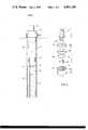
- FIG. 1is a schematic elevational view of a perforating operation within a cased wellbore in accordance with the present invention.
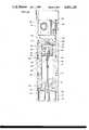
- FIG. 2is a longitudinal sectional view of the firing head assembly and a portion of the perforating gun of FIG. 1.
- FIG. 3is a more detailed view of the percussion firing assembly of the firing head assembly of FIG. 2.
- a wellhead 10has a tubing string 12 extending through the interior of a casing string 14.
- a suitable packer assembly 16which can be of any number of commonly used forms, is attached to tubing string 12 and sealingly engages casing 14 dividing the casing annulus into a lower and an upper annulus 18 and 20, respectively.
- a firing head assembly 26is attached to and underlies vent assembly 22. Mechanically coupled to firing head assembly 26 and disposed adjacent a potential hydrocarbon containing formation is perforating gun 28.
- Perforating gun 28can be of any suitable type of the style commonly referred to as a "shaped charge" perforating gun.
- Connector sub 30is a generally cylindrical member having a screw threaded proximal end for attachment to vent assembly 22 or tubing string 12.
- the second end section of connector sub 30forms a reduced diameter externally threaded section.
- Tubular firing head assembly housing 32has a screw threaded socket concentric therewith for receiving the reduced diameter threaded end of a connector sub 30.
- Seal members 34 and 36provide a fluid occlusive seal isolating wellbore fluids from the interior of housing 32.
- guide housing 38Mounted within connector sub 30 and extending into housing 32 is guide housing 38.
- Guide housing 38is a generally cylindrical member having an enlarged outer diameter upper segment 40 engaging flange 42.
- the internal bore 44 of upper segment 40is flared with the reduced diameter of the flare projecting into the internal passage 46 of the lower section of guide housing 38.
- Percussion firing assembly 58includes firing pin housing 60 threadably coupled to firing sub 62 which is further coupled to grapple sub 64 terminating with dogs 66 having beveled ends.
- Firing pin housing 60has a generally cylindrical section with a reduced decimeter upper section 68 having a generally cylindrical cavity 70 formed therein.
- Upper section 68has outwardly projecting flange 72 which allows percussion firing assembly 58 to be detachably coupled to a delivery tool, such as a setting tool affixed to a gamma ray instrument. This allows percussion firing assembly 58 to be lowered from the surface and latched into firing head assembly 26 after firing head assembly 26 and perforating gun 28 are located within the well.
- Firing pin 74is retained within cavity 70 with one end extending outside firing pin housing 60.
- a plurality of percussion ignition pins 76are attached to the other end of firing pin 74.
- three elongated ignition pins having hemispherically tapered endsare utilized.
- Ignition pins 76extend through passages within retainer ring 78.
- Frangible barrier 80isolates ignition pins 76 from explosive primer cartridges 82 which are retained within the cavities 84 within cartridge retainer 86.
- Alignment of ignition pins 76 with primer cartridges 82is provided by alignment pin 88 which inserts into bore 90 of retainer ring 78 and bore 92 of cartridge retainer 86. Additionally, seal member 94 fits within circular groove 96 in cartridge retainer 86.
- sub 62has a first elongated bore 98 located along the longitudinal axis with a centrally located cavity 100 approximately one-half inch in diameter located at the lower end thereof.
- frangible barrier 102which along with seal member 104, are held in place by the inward flange portion of grapple sub 64 when grapple sub 64 threadably engages sub 62.
- frangible barriers 80 and 102are constructed of steel approximately 0.060 inches in thickness.
- explosive booster charge 106Located within bore 98 is explosive booster charge 106 which may be, for example a DuPont P-43 booster.
- the booster chargesare relatively insensitive and not readily detonated other than by a force of an explosive nature as provided by primer cartridges 82.
- Shaped charge 108is installed within cavity 100 in juxtaposition with booster 106 and has an axis of perforation aligned substantially along the longitudinal axis of firing head assembly 26.
- a primary stem explosive assemblyincluding primary stem housing 110 threadably connected to adapter sleeve 112.
- Primary stem housing 110has a tapered upper segment 114 below which is located a reduced outer diameter section 116 which flares into a generally circular segment 118.
- Mounted within a central cavity in upper segment 114is an explosively loaded screw port 120, such as that found in U.S. Patent Application Ser. No. 476,448 which is incorporated herein by reference.
- explosive booster charge 122located in a central passage of primary stem housing 110.
- Booster 122is preferably a model P-3 supplied by DuPont Corporation.
- booster 122Crimp-connected to booster 122 is detonator cord 124 which is further crimp-connected to explosive booster charge 126 which is preferably a Dupont Model P-43. Mounted within cavity 128 in juxtaposition with booster 126 is shaped charge 130. Cavity 128 is sealed by frangible barrier 132 and sealing member 134 which are held in place by the inward flange portion of adapter sleeve 112.
- Adapter sleeve 112includes a generally cylindrical first section 136 tapering approximate the midpoint to a reduced diameter generally second cylindrical section 138. Projecting within adapter sleeve 112 is the upper end portion of secondary stem explosive assembly.
- Secondary stem explosive assemblyincludes a elongated tubular member 140 having a first end with cavity 142 formed therein and a second threaded end 144. Installed within cavity 142 is a loaded screw port 146.
- Loaded screw port 146as with screw port 120, includes a quantity of explosive material 148 retained within a threaded member 150 commonly referred to as a screw port.
- explosive booster charge 152which in the preferred embodiment is a DuPont Model P-3, which is crimp connected to a detonator cord 154 which traverses the longitudinal bore of tubular member 140.
- Detonator cord 154is preferably, but not limited to, the type known commercially as R.D.X. plastic covered Primacord.
- the first end of elongated tubular member 140includes a tapered outer section 156, a reduced outer diameter section 158 followed by an enlarged outer diameter ring 160, an intermediate outer diameter section 162 returning to an end portion 164 having an outer diameter equal to that of the main section of tubular member 140.
- the lower end of cylindrical section 138 of adapter sleeve 112is secured to section 158 of tubular member 140 by a pair of shear pins 166.
- bushing member 168Threadably attached to second end 144 of tubular member 140 is bushing member 168 having a central bore therethrough traversed by detonator cord 154.
- Bushing member 168is mounted within a central bore 170 of coupling sub 172 which is threadably coupled to firing head assembly housing 32.
- Occlusive sealsare provided by seal members 174 between coupling sub 172 and firing head assembly housing 32, by seal members 176 between coupling sub 172 and bushing member 168 and by seal member 178 between coupling sub 172 and tubular member 140.
- Donor assembly 180mounted within coupling sub 172 is donor assembly 180 of the perforating gun detonating system.
- Donor assembly 180includes an outer housing or bushing 182 sized for insertion within bore 170 of coupling sub 172 and has a central bore therethrough.
- a pair of retainer rings 184 and 186constrain outer housing 182 within coupling sub 172 and a pair of seal members 188 provides an occlusive fluid seal therebetween.
- Mounted within an internal bore of internal member 190is shaped charge 194.
- Shaped charge 194may be of various designs known in the art, in the preferred embodiment is approximately one inch in length and one-half inch in outer diameter and having the type of explosive commonly referred to as cyclonite. Shaped charges 194, 130 and 108 are of a common design. Screw port 196 is threadably installed within bushing 182 substantially in line with the axis of perforation of the "jet" produced by shaped charge 194. Retained within the rearward portion of internal member 190 and placed in juxtaposition with shaped charge 194 is booster charge 198 which is connected to detonator cord 154 and is preferably a model P-3 booster available from DuPont Corporation.
- Coupling sub 172is threadably coupled to perforating gun 28.
- the threaded jointis provided with a fluid-tight seal by seal members 200.
- Perforating gun 28includes a carrier member 202 retained therein. Mounted along the length of carrier member 202 are a plurality of shaped charges, illustrated at 204 and 206 having their axis of perforation directed generally in the surrounding formations. Mounted within the central bore of perforating gun 28 is acceptor assembly 208 of the detonation system. Acceptor assembly 208 includes a housing or holder member 210 having a cavity formed generally centrally therein. Mounted within the cavity is a generally cup shaped pellet 212 of explosive material.
- Explosive pellet 212can be from approximately 2-6 grams of cyclonite or other suitable explosive material.
- the cavityis covered with a frangible barrier 214, such as a relatively thin piece of aluminum.
- Explosive booster charge 216is connected by suitable means, such as a crimped-connection, to detonator cord 218.
- Detonator cord 218extends the length of the perforating gun 28 and provides the detonation of any shaped charges mounted therein.
- the second end of detonator cord 218may be terminated at a door assembly identical with the one described herein thereby allowing for the serial explosive coupling of additional perforating gun assemblies.
- perforating gun 28 and firing head assembly 26are attached to tubing string 12 and portioned within the casing string 14 at a location below packer assembly 16.
- Firing sub 58is lowered through tubing string 12 by means of a setting tool attached to a wireline (not shown).
- the setting toolcouples over flange 72 of sub 60.
- the setting tool and firing subare lowered through internal bore 44 of guide housing 38 until dogs 66 of grapple sub 64 engage the shoulder formed by the upper terminus of reduced diameter section 116 of primary stem housing 110.
- shaped charge 108Upon ignition, shaped charge 108 forms a "jet" which penetrates frangible barrier 102 and screw port 120 detonating the explosives material within screw port 120 thereby detonating booster charge 122.
- the detonation of booster charge 122is coupled through detonator cord 124 to detonate booster charge 126 which in turn detonates shaped charge 130.
- the detonation of shaped charge 130causes a jet to form penetrating frangible barrier 132 and screw port 150 igniting explosive material 148 thereby igniting explosive booster charge 152.
- the detonation of booster charge 152causes detonation wave to travel through detonator cord 154 to booster charge 154 to booster charge 192.
- Booster charge 198transfers the detonation wave into shaped charge 194 causing a jet to be formed.
- the jetinturn detonates explosive pellet 212 thereby causing ignition of explosive booster charge 216.
- the detonation of booster charge 216is transferred onto detonator cord 218 further detonating shaped charges 204, 206 and the other shaped charges in perforating gun 28, or subsequent perforating guns attached thereto.
- an overshot grappleis lowered into the tubing string by means of a slick line or wireline.
- the grappleis lowered into guide housing 38 until the grapple engages flang 72 of percussion firing assembly 58.
- Upward tensionis exerted causing shear pins 166 to break allowing percussion firing assembly 58 and primary stem housing 110 to be removed from firing head assembly housing 32.
- an electrical firing headcan be attached to a wireline and lowered through tubing string 12 into firing head assembly 26.
- the electrical firing headis equipped with a grapple sub identical to grapple sub 64.
- the electrical firing headis lowered into firing head assembly 32 until the dogs, which are identical to dogs 66 of grapple sub 64, clamp over end portion 164 onto the shoulder of elongated tubular member 140 of the secondary stem explosive assembly.
- An electrical signalcan then be transmitted from the surface to a detonator located in the electrical firing head, thereby igniting a shaped charge which forms a jet further igniting explosive material 148 and booster charge 152 which detonates the system in the manner hereinbefore described.
- the electrical firing headfails to detonate the perforating gun the electrical firing head is pulled off by tension from the wireline and is removed from the well.
- Perforating gun 28 and firing head assembly 26can then be removed by pulling tubing string 12. Since no primary explosives are present the danger of accidental ignition during the removal process are all but eliminated.
Landscapes
- Engineering & Computer Science (AREA)
- Geology (AREA)
- Life Sciences & Earth Sciences (AREA)
- Mining & Mineral Resources (AREA)
- Physics & Mathematics (AREA)
- Environmental & Geological Engineering (AREA)
- Fluid Mechanics (AREA)
- General Life Sciences & Earth Sciences (AREA)
- Geochemistry & Mineralogy (AREA)
- General Engineering & Computer Science (AREA)
- Portable Nailing Machines And Staplers (AREA)
- Drilling And Exploitation, And Mining Machines And Methods (AREA)
- Pressure Welding/Diffusion-Bonding (AREA)
Abstract
Description
This invention relates generally to subsurface well apparatus and more specifically, to methods and apparatus for perforating subsurface earth formations utilizing a tubing conveyed perforating apparatus.
It has become common practice in the completion of oil and gas wells to perforate the well casings and the surrounding formations to bring a well into production. One method of providing this capability has a perforating apparatus attached to the end of a tubing string which is lowered and set in place when the perforating apparatus is opposite the formation to be produced. The perforating apparatus may then be detonated and the well placed into production through the tubing strings.
The systems for firing the perforating apparatus have typically been either an electrical firing system or a non-electric percussion firing system. Neither method has been entirely satisfactory in the past since electrical firing systems require care in connection and running because these systems can be activated from stray electrical currents. In addition, electrical connections can be short-circuited by moisture. Percussion firing systems commonly have some primary explosives in the perforating apparatus while it is affixed to the tubing and lowered into position. As a result of the deficiencies of these firing systems, accidental and premature firings are a possibility. Further, in the event of a malfunction, making removal of a perforating apparatus necessary, the chance of accidental ignition of the perforating apparatus could prove dangerous to personnel.
These and other disadvantages are overcome with the present invention by providing a method and an apparatus for perforating well casing and the surrounding earth formations using a primary percussion firing system which is installed in the perforating assembly only after the perforating apparatus has been set and additionally by providing for removal of the percussion firing system in case of malfunction and installation of a secondary electrical firing system which likewise can be removed in case of malfunction.
In a preferred embodiment of the invention, a perforating system is provided which, in its overall concept, includes a perforating gun and a firing head assembly which are coupled to a tubing string and positioned thereby within a well adjacent a formation to be perforated. A percussion firing system includes a grapple end portion and an outwardly flared end portion for detachable coupling to a setting tool. The setting tool and the attached percussion firing system are lowered through the tubing string, into the firing head assembly where the grapple portion latches onto a first detonator stem. The setting tool and the wireline are removed leaving an armed firing system. To initiate the firing system an impact bar is dropped through the tubing string impacting a firing pin in the percussion firing system. The firing pin in turn impacts a plurality of explosive primer cartridges. The explosive force of the primer cartridges sets off a booster cartridge which sets up a detonating wave in a section of detonator cord which further detonates a shaped charge having an axis of perforation aligned substantially along the longitudinal axis of the firing head assembly. The jet from the shaped charge penetrates a loaded screw port mounted in the first detonator stem. The detonation of the loaded screw port is coupled by means of two booster charges and a length of detonator cord to a second shaped charge. The jet formed thereby detonates an explosively loaded screw port located in a second detonator stem. The detonation of the screw port is coupled by a booster charge, onto a length of detonator cord terminating at another booster charge in juxtaposition to a shaped charge. The jet from the shaped charge detonates a loaded screw port which transfers a detonation wave to a length of detonator cord which traverses the perforating gun thereby detonating the shaped charges therein to perforate the adjacent formations.
In the event ignition of the perforating gun is not caused by the impact bar hitting the firing pin an overshot grapple is lowered through the tubing string and engages an upper flared portion of the percussion firing system. Upward tension detaches the percussion firing system along with the first detonator stem which are removed from the well. An electrical firing head is lowered through the tubing string into the firing head assembly. A grapple end portion of the electrical firing head latches onto an end flared portion of the second detonator stem. An electrical signal detonates a shaped charge, the jet which detonates the loaded screw port in the second detonator stem thereby causing the detonation of the perforating gun in the above described manner. Should once again detonation not occur the electrical firing head is removed leaving a perforating system having no primary explosive therein. Now unarmed, the perforating gun and the firing head assembly can be removed from the well by pulling the tubing string.
These and other features and advantages of the present invention will be more readily understood by those skilled in the art from a reading of the following detailed description with reference to the accompanying drawings.
FIG. 1 is a schematic elevational view of a perforating operation within a cased wellbore in accordance with the present invention.
FIG. 2 is a longitudinal sectional view of the firing head assembly and a portion of the perforating gun of FIG. 1.
FIG. 3 is a more detailed view of the percussion firing assembly of the firing head assembly of FIG. 2.
Referring now to the drawings in more detail, particularly to FIG. 1, there is illustrated a tubing conveyed perforating system in accordance with the present invention. Awellhead 10 has atubing string 12 extending through the interior of acasing string 14. Asuitable packer assembly 16, which can be of any number of commonly used forms, is attached totubing string 12 and sealingly engagescasing 14 dividing the casing annulus into a lower and anupper annulus fluid vent assembly 22, which typically is a perforated nipple or a tubing activated sub, is attached totubing string 12 belowpacker assembly 16 and includes a plurality ofports 24 which in the open position fluidly communicatelower annulus 20 with the interior oftubing string 12. Afiring head assembly 26 is attached to and underliesvent assembly 22. Mechanically coupled to firinghead assembly 26 and disposed adjacent a potential hydrocarbon containing formation is perforatinggun 28. Perforatinggun 28 can be of any suitable type of the style commonly referred to as a "shaped charge" perforating gun.
Referring now to FIG. 2 there is illustrated partly in longitudinal sectionfiring head assembly 26 attached to the upper end of perforatinggun 28.Connector sub 30 is a generally cylindrical member having a screw threaded proximal end for attachment tovent assembly 22 ortubing string 12. The second end section ofconnector sub 30 forms a reduced diameter externally threaded section. Tubular firinghead assembly housing 32 has a screw threaded socket concentric therewith for receiving the reduced diameter threaded end of aconnector sub 30.Seal members housing 32.
Mounted withinconnector sub 30 and extending intohousing 32 isguide housing 38.Guide housing 38 is a generally cylindrical member having an enlarged outer diameterupper segment 40engaging flange 42. Theinternal bore 44 ofupper segment 40 is flared with the reduced diameter of the flare projecting into theinternal passage 46 of the lower section ofguide housing 38. Attached to guidehousing 38, by suitable means such asscrews centralizers Centralizers guide housing 38 located substantially within the center of theinternal bore 56 of firinghead assembly housing 32.
A better understanding of the firing system can be had by reference to FIGS. 2 and 3 where there is illustrated in detail the percussion firing system ofpercussion firing assembly 58. Identical reference numbers are used for identical elements in these figures.Firing pin 74 is retained withincavity 70 with one end extending outsidefiring pin housing 60. A plurality ofpercussion ignition pins 76 are attached to the other end offiring pin 74. In the preferred embodiment three elongated ignition pins having hemispherically tapered ends are utilized. Ignition pins 76 extend through passages withinretainer ring 78.Frangible barrier 80 isolates ignition pins 76 fromexplosive primer cartridges 82 which are retained within thecavities 84 withincartridge retainer 86. Alignment of ignition pins 76 withprimer cartridges 82 is provided byalignment pin 88 which inserts intobore 90 ofretainer ring 78 and bore 92 ofcartridge retainer 86. Additionally,seal member 94 fits withincircular groove 96 incartridge retainer 86.
Returning now to FIG. 2,sub 62 has a first elongated bore 98 located along the longitudinal axis with a centrally locatedcavity 100 approximately one-half inch in diameter located at the lower end thereof. The opening ofcavity 100 is covered byfrangible barrier 102 which along withseal member 104, are held in place by the inward flange portion of grapplesub 64 when grapplesub 64 threadably engagessub 62. In the preferred embodimentfrangible barriers bore 98 isexplosive booster charge 106 which may be, for example a DuPont P-43 booster. The booster charges are relatively insensitive and not readily detonated other than by a force of an explosive nature as provided byprimer cartridges 82.Shaped charge 108 is installed withincavity 100 in juxtaposition withbooster 106 and has an axis of perforation aligned substantially along the longitudinal axis of firinghead assembly 26.
Attached to grapplesub 64 is a primary stem explosive assembly includingprimary stem housing 110 threadably connected toadapter sleeve 112.Primary stem housing 110 has a taperedupper segment 114 below which is located a reducedouter diameter section 116 which flares into a generallycircular segment 118. Mounted within a central cavity inupper segment 114 is an explosivelyloaded screw port 120, such as that found in U.S. Patent Application Ser. No. 476,448 which is incorporated herein by reference. In juxtaposition with loadedscrew port 120 isexplosive booster charge 122 located in a central passage ofprimary stem housing 110.Booster 122 is preferably a model P-3 supplied by DuPont Corporation. Crimp-connected tobooster 122 isdetonator cord 124 which is further crimp-connected toexplosive booster charge 126 which is preferably a Dupont Model P-43. Mounted withincavity 128 in juxtaposition withbooster 126 is shapedcharge 130.Cavity 128 is sealed byfrangible barrier 132 and sealingmember 134 which are held in place by the inward flange portion ofadapter sleeve 112.
Threadably attached tosecond end 144 oftubular member 140 is bushingmember 168 having a central bore therethrough traversed bydetonator cord 154. Bushingmember 168 is mounted within acentral bore 170 ofcoupling sub 172 which is threadably coupled to firinghead assembly housing 32. Occlusive seals are provided byseal members 174 betweencoupling sub 172 and firinghead assembly housing 32, byseal members 176 betweencoupling sub 172 andbushing member 168 and byseal member 178 betweencoupling sub 172 andtubular member 140.
Mounted withincoupling sub 172 isdonor assembly 180 of the perforating gun detonating system.Donor assembly 180 includes an outer housing orbushing 182 sized for insertion withinbore 170 ofcoupling sub 172 and has a central bore therethrough. A pair of retainer rings 184 and 186 constrainouter housing 182 withincoupling sub 172 and a pair ofseal members 188 provides an occlusive fluid seal therebetween. Retained within the central bore ofbushing 182 and extending rearwardly therefrom isinternal member 190 having a pair ofseal members 192 thereabout. Mounted within an internal bore ofinternal member 190 is shapedcharge 194.Shaped charge 194 may be of various designs known in the art, in the preferred embodiment is approximately one inch in length and one-half inch in outer diameter and having the type of explosive commonly referred to as cyclonite.Shaped charges Screw port 196 is threadably installed withinbushing 182 substantially in line with the axis of perforation of the "jet" produced byshaped charge 194. Retained within the rearward portion ofinternal member 190 and placed in juxtaposition with shapedcharge 194 isbooster charge 198 which is connected todetonator cord 154 and is preferably a model P-3 booster available from DuPont Corporation.
Couplingsub 172 is threadably coupled to perforatinggun 28. The threaded joint is provided with a fluid-tight seal byseal members 200. Perforatinggun 28 includes acarrier member 202 retained therein. Mounted along the length ofcarrier member 202 are a plurality of shaped charges, illustrated at 204 and 206 having their axis of perforation directed generally in the surrounding formations. Mounted within the central bore of perforatinggun 28 isacceptor assembly 208 of the detonation system.Acceptor assembly 208 includes a housing orholder member 210 having a cavity formed generally centrally therein. Mounted within the cavity is a generally cup shapedpellet 212 of explosive material.Explosive pellet 212 can be from approximately 2-6 grams of cyclonite or other suitable explosive material. The cavity is covered with afrangible barrier 214, such as a relatively thin piece of aluminum.Explosive booster charge 216 is connected by suitable means, such as a crimped-connection, todetonator cord 218.Detonator cord 218 extends the length of the perforatinggun 28 and provides the detonation of any shaped charges mounted therein. The second end ofdetonator cord 218 may be terminated at a door assembly identical with the one described herein thereby allowing for the serial explosive coupling of additional perforating gun assemblies.
In the operation of the perforating system described in the Figures, perforatinggun 28 and firinghead assembly 26 are attached totubing string 12 and portioned within thecasing string 14 at a location belowpacker assembly 16. In accordance with the present invention no primary explosives are present in the perforating gun/firing head assembly during this operation. Firingsub 58 is lowered throughtubing string 12 by means of a setting tool attached to a wireline (not shown). The setting tool couples overflange 72 ofsub 60. By means of the wireline, the setting tool and firing sub are lowered throughinternal bore 44 ofguide housing 38 untildogs 66 of grapplesub 64 engage the shoulder formed by the upper terminus of reduceddiameter section 116 ofprimary stem housing 110. Oncesub 60 is latched in place the setting tool and the wire line are removed fromtubing string 12. To instigate ignition of perforatinggun 28 an impact bar, commonly referred to as a "go devil" is dropped from the surface throughtubing string 12. The impact bar passes throughinternal bores guide housing 38hitting firing pin 74 driving ignition pins 76 throughfrangible barrier 80 ontoprimer cartridges 82. The explosion ofprimer cartridges 82 detonatesbooster charge 106 further detonating shapedcharge 108.
Upon ignition, shapedcharge 108 forms a "jet" which penetratesfrangible barrier 102 and screwport 120 detonating the explosives material withinscrew port 120 thereby detonatingbooster charge 122. The detonation ofbooster charge 122 is coupled throughdetonator cord 124 to detonatebooster charge 126 which in turn detonates shapedcharge 130. The detonation of shapedcharge 130 causes a jet to form penetratingfrangible barrier 132 and screwport 150 ignitingexplosive material 148 thereby ignitingexplosive booster charge 152. The detonation ofbooster charge 152 causes detonation wave to travel throughdetonator cord 154 tobooster charge 154 tobooster charge 192.Booster charge 198 transfers the detonation wave into shapedcharge 194 causing a jet to be formed. The jet inturn detonatesexplosive pellet 212 thereby causing ignition ofexplosive booster charge 216. The detonation ofbooster charge 216 is transferred ontodetonator cord 218 further detonating shapedcharges gun 28, or subsequent perforating guns attached thereto.
In the event ignition of the perforating gun shaped charges is not caused by the impact bar, the present system provides a back-up electrical ignition method. An overshot grapple is lowered into the tubing string by means of a slick line or wireline. The grapple is lowered intoguide housing 38 until the grapple engagesflang 72 ofpercussion firing assembly 58. Upward tension is exerted causing shear pins 166 to break allowingpercussion firing assembly 58 andprimary stem housing 110 to be removed from firinghead assembly housing 32. Withpercussion firing assembly 58 andprimary stem housing 110 removed an electrical firing head can be attached to a wireline and lowered throughtubing string 12 into firinghead assembly 26. The electrical firing head is equipped with a grapple sub identical to grapplesub 64. The electrical firing head is lowered into firinghead assembly 32 until the dogs, which are identical todogs 66 of grapplesub 64, clamp overend portion 164 onto the shoulder of elongatedtubular member 140 of the secondary stem explosive assembly. An electrical signal can then be transmitted from the surface to a detonator located in the electrical firing head, thereby igniting a shaped charge which forms a jet further ignitingexplosive material 148 andbooster charge 152 which detonates the system in the manner hereinbefore described. Should the electrical firing head fail to detonate the perforating gun the electrical firing head is pulled off by tension from the wireline and is removed from the well. Perforatinggun 28 and firinghead assembly 26 can then be removed by pullingtubing string 12. Since no primary explosives are present the danger of accidental ignition during the removal process are all but eliminated.
Many modifications and variations besides those specifically mentioned may be made in the techniques and structures described herein and depicted in the accompanying drawing without departing substantially from the concept of the present invention. Accordingly, it should be clearly understood that the form of the invention described and illustrated herein is exemplary only, and is not intended as a limitation on the scope of the present invention.
Claims (20)
1. A method for perforating subsurface earth formations surrounding a borehole, comprising the steps of:
positioning on the end of a tubing string a perforating gun and a firing head assembly within a borehole,
said firing head assembly including first and second explosive detonator assemblies mechanically and explosively serially aligned, said first detonator assembly detachably mechanically coupled to said second detonator assembly;
subsequently lowering through said tubing string a percussion firing assembly into coupling relationship within said firing head assembly; and
dropping an impact member through said tubing string, the collision of said impact member with said percussion firing assembly for detonating said percussion firing assembly to thereby detonate said firing head assembly and said perforating gun.
2. The method of claim 1 further including the steps of:
removing said percussion firing assembly and said second explosive detonator assembly portion of said firing head assembly from said borehole;
subsequently lowering an electrical firing assembly into coupling relationship within said firing head assembly; and
passing an electrical control signal to said electrical firing assembly for detonating said firing head assembly to thereby detonate said perforating gun.
3. The method of claim 2 further including the steps of:
removing said electrical firing assembly from said borehole; and
subsequently removing said perforating gun and said firing head assembly from said borehole, said perforating gun and said firing head assembly including no initiating explosives therein.
4. Apparatus for perforating subsurface earth formations surrounding a borehole, comprising:
an elongated perforating gun having a plurality of radially directed shaped charges mounted therein;
a first explosive detonator assembly mechanically coupled to said perforating gun;
a second explosive detonator assembly mechanically coupled to said first detonator assembly, said second explosive detonator assembly being selectively detachable from said first explosive detonator assembly and aligned for transferring a detonating wave from said second detonator assembly to said first detonator asssembly; and
a percussion firing assembly adapted for latching engagement with said second detonator assembly.
5. The apparatus of claim 4 wherein said first detonator assembly comprises:
an elongated member having a central bore therethrough;
an explosively loaded screw port mounted within one end of said elongated member;
an explosive booster juxtaposed with said loaded screw port;
a length of detonator cord having a first end coupled to said explosive booster, said detonator cord
traversing said central bore in said elongated member; and
a detonating wave propagation means coupled to the second end of said detonator cord for explosively coupling a detonation wave to said perforating gun.
6. The apparatus of claim 5 wherein said propagation assembly comprises:
a shaped charge having the axis of perforation aligned generally along the longitudinal axis of said first detonator assembly and
an explosive booster connected to the second end of said detonator cord.
7. The apparatus of claim 4 wherein said second detonator assembly comprises:
a housing member having a reduced diameter shoulder proximate a first end thereof;
an explosively loaded screw port mounted within said first end of said housing member;
a first explosive booster juxtaposed with said screw port;
a length of detonator cord having a first end coupled to said first booster;
a second explosive booster coupled to the second end said detonator cord; and
a shaped charge juxtaposed with said second booster having the axis of perforation generally along the longitudinal axis of said housing.
8. The apparatus of claim 4 wherein said percussion firing assembly comprises:
a housing having an outwardly flared first end portion, and a second end grapple portion, said grapple portion having a plurality of elongated grapple arms terminating with inwardly directed dogs;
a percussion firing pin a portion thereof extending from said first end portion;
an impact sensitive explosive primer located proximate said percussion firing pin;
a shaped charge having the axis of perforation generally along the longitudinal axis of said housing; and
means for carrying a detonating wave from said explosive primer to said shaped charge.
9. The apparatus of claim 8 wherein said percussion firing pin further comprises a plurality of hemispherically tapered percussion ignition pins extending from said firing pin.
10. The apparatus of claim 9 wherein said impact sensitive explosive primer further includes a plurality of explosive primer cartridges disposed beneath said plurality of ignition pins.
11. A perforating apparatus for perforating subsurface earth formations surrounding a borehole including a perforating gun adapted to be conveyed into a borehole on the end of a length of tubing string and having a firing assembly interposed therebetween said firing assembly comprising:
an elongated tubular housing coupled between said perforating gun and said tubing string;
a first explosive detonator assembly coupled to said perforating gun for transferring a detonating wave into said gun;
a second explosive detonator assembly detachably coupled to said first detonator assembly for transferring a detonating wave into said first
detonator assembly; and
an attachable impact sensitive firing assembly adapted to be lowered through said tubing string into latching engagement with said second explosive detonator assembly.
12. The apparatus of claim 11 further comprising:
a guide member coaxially located within said tubular housing proximate said tubing strings; and
centralizer means for centering said impact sensitive firing assembly within said guide means.
13. The apparatus of claim 12 wherein said first explosive detonator assembly further comprises:
an elongated tubular member located generally on the longitudinal axis of said housing;
an explosively loaded screw port mounted in one end of said tubular member;
a shaped charge mounted at the second end of said tubular member having the axis off perforation in line with said perforating gun; and
means for carrying a detonation wave from said screw port to said shaped charge.
14. The apparatus of claim 13 further comprising explosive means located in said perforating gun substantially in line with said shaped charge located in said first explosive detonator assembly for transferring a detonating wave into said perforating gun.
15. The apparatus of claim 14 wherein said second detonator assembly further comprises:
an elongated housing having a reduced diameter shoulder proximate one end thereof;
an explosively loaded screw mounted in said one end of said housing;
a shaped charge mounted in the second end of said housing having the axis of perforation in line with said screw port within said first detonator assembly; and
shear members for detachably coupling the second end of said housing to said first detonator assembly.
16. The apparatus of claim 15 further comprising shear members coupling said second end of said housing of said second detonator assembly with said first detonator assembly.
17. The apparatus of claim 16 wherein said impact sensitive firing assembly further comprises:
a housing member having an outwardly flared first end position and a second grapple end portion for latching engagement with said second detonator assembly;
a percussion firing pin extending from said first end portion;
impact sensitive explosive primer located in line with said firing pin;
a shaped charge located in said housing member having an axis of perforation generally in line with said screw port within said second detonator assembly; and
means for carrying a detonating wave from said explosive primer to said shaped charge.
18. The apparatus of claim 17 wherein said firing pin further comprises three hemispherically tapered ignition pins extending from said firing pin.
19. The apparatus of claim 18 wherein said explosive primer further comprises three explosive pellets located beneath said three ignition pins.
20. The apparatus of claim 19 further comprising a frangible member interposed between said explosive pellets and said ignition pins.
Priority Applications (2)
| Application Number | Priority Date | Filing Date | Title |
|---|---|---|---|
| US06/516,811US4491185A (en) | 1983-07-25 | 1983-07-25 | Method and apparatus for perforating subsurface earth formations |
| US06/670,835US4790385A (en) | 1983-07-25 | 1984-11-13 | Method and apparatus for perforating subsurface earth formations |
Applications Claiming Priority (1)
| Application Number | Priority Date | Filing Date | Title |
|---|---|---|---|
| US06/516,811US4491185A (en) | 1983-07-25 | 1983-07-25 | Method and apparatus for perforating subsurface earth formations |
Related Child Applications (1)
| Application Number | Title | Priority Date | Filing Date |
|---|---|---|---|
| US06/670,835Continuation-In-PartUS4790385A (en) | 1983-07-25 | 1984-11-13 | Method and apparatus for perforating subsurface earth formations |
Publications (1)
| Publication Number | Publication Date |
|---|---|
| US4491185Atrue US4491185A (en) | 1985-01-01 |
Family
ID=24057189
Family Applications (1)
| Application Number | Title | Priority Date | Filing Date |
|---|---|---|---|
| US06/516,811Expired - Fee RelatedUS4491185A (en) | 1983-07-25 | 1983-07-25 | Method and apparatus for perforating subsurface earth formations |
Country Status (1)
| Country | Link |
|---|---|
| US (1) | US4491185A (en) |
Cited By (73)
| Publication number | Priority date | Publication date | Assignee | Title |
|---|---|---|---|---|
| US4598776A (en)* | 1985-06-11 | 1986-07-08 | Baker Oil Tools, Inc. | Method and apparatus for firing multisection perforating guns |
| US4611660A (en)* | 1985-06-06 | 1986-09-16 | Baker Oil Tools, Inc. | Wireline conveyed firing mechanism for well perforating gun |
| US4658900A (en)* | 1985-06-06 | 1987-04-21 | Baker Oil Tools, Inc. | High energy firing head for well perforating guns |
| US4850438A (en)* | 1984-04-27 | 1989-07-25 | Halliburton Company | Modular perforating gun |
| US4913053A (en)* | 1986-10-02 | 1990-04-03 | Western Atlas International, Inc. | Method of increasing the detonation velocity of detonating fuse |
| GB2232463A (en)* | 1988-12-01 | 1990-12-12 | Dresser Ind | Firing apparatus for releasably engaging well bore perforating apparatus |
| EP0404686A1 (en)* | 1989-06-23 | 1990-12-27 | Schlumberger Limited | Pump apparatus including a firing head for use with a perforating gun on a tubing string |
| US5040597A (en)* | 1989-06-23 | 1991-08-20 | Schlumberger Technology Corporation | Well apparatus including a pump and a firing head adapted to be inserted into a tubing which includes a perforating gun |
| US5044388A (en)* | 1989-02-13 | 1991-09-03 | Dresser Industries, Inc. | Perforating gun pressure bleed device |
| US5058680A (en)* | 1989-06-23 | 1991-10-22 | Schlumberger Technology Corportion | Method of detonating a perforating apparatus on a tubing including lowering one end of a pump and a firing head into said tubing |
| US5088557A (en)* | 1990-03-15 | 1992-02-18 | Dresser Industries, Inc. | Downhole pressure attenuation apparatus |
| US5571986A (en)* | 1994-08-04 | 1996-11-05 | Marathon Oil Company | Method and apparatus for activating an electric wireline firing system |
| US5603379A (en)* | 1994-08-31 | 1997-02-18 | Halliburton Company | Bi-directional explosive transfer apparatus and method |
| US6662883B2 (en) | 2001-09-07 | 2003-12-16 | Lri Oil Tools Inc. | Charge tube assembly for a perforating gun |
| US20050183610A1 (en)* | 2003-09-05 | 2005-08-25 | Barton John A. | High pressure exposed detonating cord detonator system |
| US20090183916A1 (en)* | 2005-10-18 | 2009-07-23 | Owen Oil Tools Lp | System and method for enhanced wellbore perforations |
| US8919444B2 (en) | 2012-01-18 | 2014-12-30 | Owen Oil Tools Lp | System and method for enhanced wellbore perforations |
| US10024145B1 (en) | 2014-12-30 | 2018-07-17 | The Gasgun, Inc. | Method of creating and finishing perforations in a hydrocarbon well |
| US10188990B2 (en)* | 2014-03-07 | 2019-01-29 | Dynaenergetics Gmbh & Co. Kg | Device and method for positioning a detonator within a perforating gun assembly |
| US10472938B2 (en) | 2013-07-18 | 2019-11-12 | Dynaenergetics Gmbh & Co. Kg | Perforation gun components and system |
| CN110926287A (en)* | 2019-12-20 | 2020-03-27 | 深圳市蛇口招商港湾工程有限公司 | Cutting earth and rock excavation blasting method |
| US10845177B2 (en) | 2018-06-11 | 2020-11-24 | DynaEnergetics Europe GmbH | Conductive detonating cord for perforating gun |
| US10844696B2 (en) | 2018-07-17 | 2020-11-24 | DynaEnergetics Europe GmbH | Positioning device for shaped charges in a perforating gun module |
| USD904475S1 (en) | 2020-04-29 | 2020-12-08 | DynaEnergetics Europe GmbH | Tandem sub |
| USD908754S1 (en) | 2020-04-30 | 2021-01-26 | DynaEnergetics Europe GmbH | Tandem sub |
| US10927627B2 (en) | 2019-05-14 | 2021-02-23 | DynaEnergetics Europe GmbH | Single use setting tool for actuating a tool in a wellbore |
| US10982941B2 (en) | 2015-03-18 | 2021-04-20 | DynaEnergetics Europe GmbH | Pivotable bulkhead assembly for crimp resistance |
| USD921858S1 (en) | 2019-02-11 | 2021-06-08 | DynaEnergetics Europe GmbH | Perforating gun and alignment assembly |
| CN113685154A (en)* | 2020-05-18 | 2021-11-23 | 哈里伯顿能源服务公司 | Outward threadless baffle for perforating gun |
| US11225848B2 (en) | 2020-03-20 | 2022-01-18 | DynaEnergetics Europe GmbH | Tandem seal adapter, adapter assembly with tandem seal adapter, and wellbore tool string with adapter assembly |
| US11248452B2 (en) | 2019-04-01 | 2022-02-15 | XConnect, LLC | Bulkhead assembly for a tandem sub, and an improved tandem sub |
| US11255650B2 (en)* | 2016-11-17 | 2022-02-22 | XConnect, LLC | Detonation system having sealed explosive initiation assembly |
| US11255147B2 (en) | 2019-05-14 | 2022-02-22 | DynaEnergetics Europe GmbH | Single use setting tool for actuating a tool in a wellbore |
| US11293736B2 (en) | 2015-03-18 | 2022-04-05 | DynaEnergetics Europe GmbH | Electrical connector |
| US11293737B2 (en) | 2019-04-01 | 2022-04-05 | XConnect, LLC | Detonation system having sealed explosive initiation assembly |
| US11339614B2 (en) | 2020-03-31 | 2022-05-24 | DynaEnergetics Europe GmbH | Alignment sub and orienting sub adapter |
| US11359468B2 (en) | 2020-05-18 | 2022-06-14 | Halliburton Energy Services, Inc. | Outwardly threadless bulkhead for perforating gun |
| US11408279B2 (en) | 2018-08-21 | 2022-08-09 | DynaEnergetics Europe GmbH | System and method for navigating a wellbore and determining location in a wellbore |
| US11480038B2 (en) | 2019-12-17 | 2022-10-25 | DynaEnergetics Europe GmbH | Modular perforating gun system |
| US11499401B2 (en) | 2021-02-04 | 2022-11-15 | DynaEnergetics Europe GmbH | Perforating gun assembly with performance optimized shaped charge load |
| US11578549B2 (en) | 2019-05-14 | 2023-02-14 | DynaEnergetics Europe GmbH | Single use setting tool for actuating a tool in a wellbore |
| US11591885B2 (en) | 2018-05-31 | 2023-02-28 | DynaEnergetics Europe GmbH | Selective untethered drone string for downhole oil and gas wellbore operations |
| USD981345S1 (en) | 2020-11-12 | 2023-03-21 | DynaEnergetics Europe GmbH | Shaped charge casing |
| US11713625B2 (en) | 2021-03-03 | 2023-08-01 | DynaEnergetics Europe GmbH | Bulkhead |
| US11732556B2 (en) | 2021-03-03 | 2023-08-22 | DynaEnergetics Europe GmbH | Orienting perforation gun assembly |
| US11753889B1 (en) | 2022-07-13 | 2023-09-12 | DynaEnergetics Europe GmbH | Gas driven wireline release tool |
| US11795791B2 (en) | 2021-02-04 | 2023-10-24 | DynaEnergetics Europe GmbH | Perforating gun assembly with performance optimized shaped charge load |
| US11808098B2 (en) | 2018-08-20 | 2023-11-07 | DynaEnergetics Europe GmbH | System and method to deploy and control autonomous devices |
| US11808093B2 (en) | 2018-07-17 | 2023-11-07 | DynaEnergetics Europe GmbH | Oriented perforating system |
| USD1010758S1 (en) | 2019-02-11 | 2024-01-09 | DynaEnergetics Europe GmbH | Gun body |
| US11906278B2 (en) | 2019-04-01 | 2024-02-20 | XConnect, LLC | Bridged bulkheads for perforating gun assembly |
| US11905823B2 (en) | 2018-05-31 | 2024-02-20 | DynaEnergetics Europe GmbH | Systems and methods for marker inclusion in a wellbore |
| US11913767B2 (en) | 2019-05-09 | 2024-02-27 | XConnect, LLC | End plate for a perforating gun assembly |
| USD1019709S1 (en) | 2019-02-11 | 2024-03-26 | DynaEnergetics Europe GmbH | Charge holder |
| US11940261B2 (en) | 2019-05-09 | 2024-03-26 | XConnect, LLC | Bulkhead for a perforating gun assembly |
| US11946728B2 (en) | 2019-12-10 | 2024-04-02 | DynaEnergetics Europe GmbH | Initiator head with circuit board |
| US11952872B2 (en) | 2013-07-18 | 2024-04-09 | DynaEnergetics Europe GmbH | Detonator positioning device |
| US11988049B2 (en) | 2020-03-31 | 2024-05-21 | DynaEnergetics Europe GmbH | Alignment sub and perforating gun assembly with alignment sub |
| USD1028181S1 (en) | 2019-04-01 | 2024-05-21 | DynaEnergetics Europe GmbH | Perforating gun assembly |
| US12000267B2 (en) | 2021-09-24 | 2024-06-04 | DynaEnergetics Europe GmbH | Communication and location system for an autonomous frack system |
| US12031417B2 (en) | 2018-05-31 | 2024-07-09 | DynaEnergetics Europe GmbH | Untethered drone string for downhole oil and gas wellbore operations |
| USD1034879S1 (en) | 2019-02-11 | 2024-07-09 | DynaEnergetics Europe GmbH | Gun body |
| US12084962B2 (en) | 2020-03-16 | 2024-09-10 | DynaEnergetics Europe GmbH | Tandem seal adapter with integrated tracer material |
| US12091919B2 (en) | 2021-03-03 | 2024-09-17 | DynaEnergetics Europe GmbH | Bulkhead |
| US12139984B2 (en) | 2022-04-15 | 2024-11-12 | Dbk Industries, Llc | Fixed-volume setting tool |
| USRE50204E1 (en) | 2013-08-26 | 2024-11-12 | DynaEnergetics Europe GmbH | Perforating gun and detonator assembly |
| US12241326B2 (en) | 2019-05-14 | 2025-03-04 | DynaEnergetics Europe GmbH | Single use setting tool for actuating a tool in a wellbore |
| US12253339B2 (en) | 2021-10-25 | 2025-03-18 | DynaEnergetics Europe GmbH | Adapter and shaped charge apparatus for optimized perforation jet |
| US12312925B2 (en) | 2021-12-22 | 2025-05-27 | DynaEnergetics Europe GmbH | Manually oriented internal shaped charge alignment system and method of use |
| US12326069B2 (en) | 2020-10-20 | 2025-06-10 | DynaEnergetics Europe GmbH | Perforating gun and alignment assembly |
| US12366142B2 (en) | 2021-03-03 | 2025-07-22 | DynaEnergetics Europe GmbH | Modular perforating gun system |
| US12378833B2 (en) | 2022-07-13 | 2025-08-05 | DynaEnergetics Europe GmbH | Gas driven wireline release tool |
| US12385369B2 (en) | 2019-06-14 | 2025-08-12 | DynaEngergetics Europe GmbH | Perforating gun assembly with rotating shaped charge holder |
Citations (6)
| Publication number | Priority date | Publication date | Assignee | Title |
|---|---|---|---|---|
| US2120615A (en)* | 1937-03-04 | 1938-06-14 | King Fritz | Well gun |
| US2155322A (en)* | 1937-03-08 | 1939-04-18 | Ira J Mccullough | Gun perforator |
| US2419371A (en)* | 1939-02-02 | 1947-04-22 | Schlumberger Marcel | Cartridge |
| US2873675A (en)* | 1953-06-17 | 1959-02-17 | Borg Warner | Method and apparatus for detonating explosive devices in bore holes |
| US3710717A (en)* | 1971-05-18 | 1973-01-16 | J Tamplen | Percussion firing system |
| US3800705A (en)* | 1973-03-30 | 1974-04-02 | J Tamplen | Pressure balanced percussion firing system |
- 1983
- 1983-07-25USUS06/516,811patent/US4491185A/ennot_activeExpired - Fee Related
Patent Citations (6)
| Publication number | Priority date | Publication date | Assignee | Title |
|---|---|---|---|---|
| US2120615A (en)* | 1937-03-04 | 1938-06-14 | King Fritz | Well gun |
| US2155322A (en)* | 1937-03-08 | 1939-04-18 | Ira J Mccullough | Gun perforator |
| US2419371A (en)* | 1939-02-02 | 1947-04-22 | Schlumberger Marcel | Cartridge |
| US2873675A (en)* | 1953-06-17 | 1959-02-17 | Borg Warner | Method and apparatus for detonating explosive devices in bore holes |
| US3710717A (en)* | 1971-05-18 | 1973-01-16 | J Tamplen | Percussion firing system |
| US3800705A (en)* | 1973-03-30 | 1974-04-02 | J Tamplen | Pressure balanced percussion firing system |
Cited By (110)
| Publication number | Priority date | Publication date | Assignee | Title |
|---|---|---|---|---|
| US4850438A (en)* | 1984-04-27 | 1989-07-25 | Halliburton Company | Modular perforating gun |
| US4611660A (en)* | 1985-06-06 | 1986-09-16 | Baker Oil Tools, Inc. | Wireline conveyed firing mechanism for well perforating gun |
| GB2176880A (en)* | 1985-06-06 | 1987-01-07 | Baker Oil Tools Inc | Wireline conveyed firing mechanism for well perforating gun |
| US4658900A (en)* | 1985-06-06 | 1987-04-21 | Baker Oil Tools, Inc. | High energy firing head for well perforating guns |
| GB2176880B (en)* | 1985-06-06 | 1989-07-05 | Baker Oil Tools Inc | Wireline conveyed firing mechanism for well perforating gun |
| US4598776A (en)* | 1985-06-11 | 1986-07-08 | Baker Oil Tools, Inc. | Method and apparatus for firing multisection perforating guns |
| US4913053A (en)* | 1986-10-02 | 1990-04-03 | Western Atlas International, Inc. | Method of increasing the detonation velocity of detonating fuse |
| GB2232463A (en)* | 1988-12-01 | 1990-12-12 | Dresser Ind | Firing apparatus for releasably engaging well bore perforating apparatus |
| US5007344A (en)* | 1988-12-01 | 1991-04-16 | Dresser Industries, Inc. | Dual firing system for a perforating gun |
| US5044388A (en)* | 1989-02-13 | 1991-09-03 | Dresser Industries, Inc. | Perforating gun pressure bleed device |
| US5040597A (en)* | 1989-06-23 | 1991-08-20 | Schlumberger Technology Corporation | Well apparatus including a pump and a firing head adapted to be inserted into a tubing which includes a perforating gun |
| EP0404686A1 (en)* | 1989-06-23 | 1990-12-27 | Schlumberger Limited | Pump apparatus including a firing head for use with a perforating gun on a tubing string |
| US5050672A (en)* | 1989-06-23 | 1991-09-24 | Schlumberger Technology Corporation | Pump apparatus including a firing head for use with a perforating gun on a tubing string |
| US5058680A (en)* | 1989-06-23 | 1991-10-22 | Schlumberger Technology Corportion | Method of detonating a perforating apparatus on a tubing including lowering one end of a pump and a firing head into said tubing |
| US5088557A (en)* | 1990-03-15 | 1992-02-18 | Dresser Industries, Inc. | Downhole pressure attenuation apparatus |
| US5571986A (en)* | 1994-08-04 | 1996-11-05 | Marathon Oil Company | Method and apparatus for activating an electric wireline firing system |
| US5603379A (en)* | 1994-08-31 | 1997-02-18 | Halliburton Company | Bi-directional explosive transfer apparatus and method |
| US6662883B2 (en) | 2001-09-07 | 2003-12-16 | Lri Oil Tools Inc. | Charge tube assembly for a perforating gun |
| US20050183610A1 (en)* | 2003-09-05 | 2005-08-25 | Barton John A. | High pressure exposed detonating cord detonator system |
| US20090183916A1 (en)* | 2005-10-18 | 2009-07-23 | Owen Oil Tools Lp | System and method for enhanced wellbore perforations |
| US7913761B2 (en)* | 2005-10-18 | 2011-03-29 | Owen Oil Tools Lp | System and method for enhanced wellbore perforations |
| EP2242896A4 (en)* | 2008-01-22 | 2017-05-10 | Owen Oil Tools LP | System and method for enhanced wellbore perforations |
| US8919444B2 (en) | 2012-01-18 | 2014-12-30 | Owen Oil Tools Lp | System and method for enhanced wellbore perforations |
| US12203350B2 (en) | 2013-07-18 | 2025-01-21 | DynaEnergetics Europe GmbH | Detonator positioning device |
| US11952872B2 (en) | 2013-07-18 | 2024-04-09 | DynaEnergetics Europe GmbH | Detonator positioning device |
| US10472938B2 (en) | 2013-07-18 | 2019-11-12 | Dynaenergetics Gmbh & Co. Kg | Perforation gun components and system |
| US11608720B2 (en) | 2013-07-18 | 2023-03-21 | DynaEnergetics Europe GmbH | Perforating gun system with electrical connection assemblies |
| US12215576B2 (en) | 2013-07-18 | 2025-02-04 | DynaEnergetics Europe GmbH | Single charge perforation gun and system |
| US11125056B2 (en) | 2013-07-18 | 2021-09-21 | DynaEnergetics Europe GmbH | Perforation gun components and system |
| US11542792B2 (en) | 2013-07-18 | 2023-01-03 | DynaEnergetics Europe GmbH | Tandem seal adapter for use with a wellbore tool, and wellbore tool string including a tandem seal adapter |
| US11788389B2 (en) | 2013-07-18 | 2023-10-17 | DynaEnergetics Europe GmbH | Perforating gun assembly having seal element of tandem seal adapter and coupling of housing intersecting with a common plane perpendicular to longitudinal axis |
| US10844697B2 (en) | 2013-07-18 | 2020-11-24 | DynaEnergetics Europe GmbH | Perforation gun components and system |
| US11661823B2 (en) | 2013-07-18 | 2023-05-30 | DynaEnergetics Europe GmbH | Perforating gun assembly and wellbore tool string with tandem seal adapter |
| US11648513B2 (en) | 2013-07-18 | 2023-05-16 | DynaEnergetics Europe GmbH | Detonator positioning device |
| US12060778B2 (en) | 2013-07-18 | 2024-08-13 | DynaEnergetics Europe GmbH | Perforating gun assembly |
| US12078038B2 (en) | 2013-07-18 | 2024-09-03 | DynaEnergetics Europe GmbH | Perforating gun orientation system |
| USRE50204E1 (en) | 2013-08-26 | 2024-11-12 | DynaEnergetics Europe GmbH | Perforating gun and detonator assembly |
| US10188990B2 (en)* | 2014-03-07 | 2019-01-29 | Dynaenergetics Gmbh & Co. Kg | Device and method for positioning a detonator within a perforating gun assembly |
| US10507433B2 (en) | 2014-03-07 | 2019-12-17 | Dynaenergetics Gmbh & Co. Kg | Device and method for positioning a detonator within a perforating gun assembly |
| US10024145B1 (en) | 2014-12-30 | 2018-07-17 | The Gasgun, Inc. | Method of creating and finishing perforations in a hydrocarbon well |
| US10760384B2 (en) | 2014-12-30 | 2020-09-01 | The Gasgun, Llc | Method of creating and finishing perforations in a hydrocarbon well |
| US10982941B2 (en) | 2015-03-18 | 2021-04-20 | DynaEnergetics Europe GmbH | Pivotable bulkhead assembly for crimp resistance |
| US11293736B2 (en) | 2015-03-18 | 2022-04-05 | DynaEnergetics Europe GmbH | Electrical connector |
| US11906279B2 (en) | 2015-03-18 | 2024-02-20 | DynaEnergetics Europe GmbH | Electrical connector |
| US11255650B2 (en)* | 2016-11-17 | 2022-02-22 | XConnect, LLC | Detonation system having sealed explosive initiation assembly |
| US11591885B2 (en) | 2018-05-31 | 2023-02-28 | DynaEnergetics Europe GmbH | Selective untethered drone string for downhole oil and gas wellbore operations |
| US12031417B2 (en) | 2018-05-31 | 2024-07-09 | DynaEnergetics Europe GmbH | Untethered drone string for downhole oil and gas wellbore operations |
| US11905823B2 (en) | 2018-05-31 | 2024-02-20 | DynaEnergetics Europe GmbH | Systems and methods for marker inclusion in a wellbore |
| US12044108B2 (en) | 2018-06-11 | 2024-07-23 | DynaEnergetics Europe GmbH | Perforating gun with conductive detonating cord |
| US11385036B2 (en) | 2018-06-11 | 2022-07-12 | DynaEnergetics Europe GmbH | Conductive detonating cord for perforating gun |
| US10845177B2 (en) | 2018-06-11 | 2020-11-24 | DynaEnergetics Europe GmbH | Conductive detonating cord for perforating gun |
| US10920543B2 (en) | 2018-07-17 | 2021-02-16 | DynaEnergetics Europe GmbH | Single charge perforating gun |
| US11339632B2 (en) | 2018-07-17 | 2022-05-24 | DynaEnergetics Europe GmbH | Unibody gun housing, tool string incorporating same, and method of assembly |
| US11525344B2 (en) | 2018-07-17 | 2022-12-13 | DynaEnergetics Europe GmbH | Perforating gun module with monolithic shaped charge positioning device |
| US11808093B2 (en) | 2018-07-17 | 2023-11-07 | DynaEnergetics Europe GmbH | Oriented perforating system |
| US11773698B2 (en) | 2018-07-17 | 2023-10-03 | DynaEnergetics Europe GmbH | Shaped charge holder and perforating gun |
| US10844696B2 (en) | 2018-07-17 | 2020-11-24 | DynaEnergetics Europe GmbH | Positioning device for shaped charges in a perforating gun module |
| US11808098B2 (en) | 2018-08-20 | 2023-11-07 | DynaEnergetics Europe GmbH | System and method to deploy and control autonomous devices |
| US11408279B2 (en) | 2018-08-21 | 2022-08-09 | DynaEnergetics Europe GmbH | System and method for navigating a wellbore and determining location in a wellbore |
| USD1010758S1 (en) | 2019-02-11 | 2024-01-09 | DynaEnergetics Europe GmbH | Gun body |
| USD1019709S1 (en) | 2019-02-11 | 2024-03-26 | DynaEnergetics Europe GmbH | Charge holder |
| USD1034879S1 (en) | 2019-02-11 | 2024-07-09 | DynaEnergetics Europe GmbH | Gun body |
| USD935574S1 (en) | 2019-02-11 | 2021-11-09 | DynaEnergetics Europe GmbH | Inner retention ring |
| USD921858S1 (en) | 2019-02-11 | 2021-06-08 | DynaEnergetics Europe GmbH | Perforating gun and alignment assembly |
| USD1028181S1 (en) | 2019-04-01 | 2024-05-21 | DynaEnergetics Europe GmbH | Perforating gun assembly |
| US11248452B2 (en) | 2019-04-01 | 2022-02-15 | XConnect, LLC | Bulkhead assembly for a tandem sub, and an improved tandem sub |
| US11293737B2 (en) | 2019-04-01 | 2022-04-05 | XConnect, LLC | Detonation system having sealed explosive initiation assembly |
| US12116871B2 (en) | 2019-04-01 | 2024-10-15 | DynaEnergetics Europe GmbH | Retrievable perforating gun assembly and components |
| US11906278B2 (en) | 2019-04-01 | 2024-02-20 | XConnect, LLC | Bridged bulkheads for perforating gun assembly |
| US11940261B2 (en) | 2019-05-09 | 2024-03-26 | XConnect, LLC | Bulkhead for a perforating gun assembly |
| US11913767B2 (en) | 2019-05-09 | 2024-02-27 | XConnect, LLC | End plate for a perforating gun assembly |
| US12241326B2 (en) | 2019-05-14 | 2025-03-04 | DynaEnergetics Europe GmbH | Single use setting tool for actuating a tool in a wellbore |
| US10927627B2 (en) | 2019-05-14 | 2021-02-23 | DynaEnergetics Europe GmbH | Single use setting tool for actuating a tool in a wellbore |
| US11578549B2 (en) | 2019-05-14 | 2023-02-14 | DynaEnergetics Europe GmbH | Single use setting tool for actuating a tool in a wellbore |
| US11255147B2 (en) | 2019-05-14 | 2022-02-22 | DynaEnergetics Europe GmbH | Single use setting tool for actuating a tool in a wellbore |
| US12385369B2 (en) | 2019-06-14 | 2025-08-12 | DynaEngergetics Europe GmbH | Perforating gun assembly with rotating shaped charge holder |
| US11946728B2 (en) | 2019-12-10 | 2024-04-02 | DynaEnergetics Europe GmbH | Initiator head with circuit board |
| US12332034B2 (en) | 2019-12-10 | 2025-06-17 | DynaEnergetics Europe GmbH | Initiator head with circuit board |
| US11480038B2 (en) | 2019-12-17 | 2022-10-25 | DynaEnergetics Europe GmbH | Modular perforating gun system |
| CN110926287A (en)* | 2019-12-20 | 2020-03-27 | 深圳市蛇口招商港湾工程有限公司 | Cutting earth and rock excavation blasting method |
| US12084962B2 (en) | 2020-03-16 | 2024-09-10 | DynaEnergetics Europe GmbH | Tandem seal adapter with integrated tracer material |
| US12410669B2 (en) | 2020-03-20 | 2025-09-09 | DynaEnergetics Europe GmbH | Adapter assembly for use with a wellbore tool string |
| USD1041608S1 (en) | 2020-03-20 | 2024-09-10 | DynaEnergetics Europe GmbH | Outer connector |
| US11225848B2 (en) | 2020-03-20 | 2022-01-18 | DynaEnergetics Europe GmbH | Tandem seal adapter, adapter assembly with tandem seal adapter, and wellbore tool string with adapter assembly |
| US11814915B2 (en) | 2020-03-20 | 2023-11-14 | DynaEnergetics Europe GmbH | Adapter assembly for use with a wellbore tool string |
| US11988049B2 (en) | 2020-03-31 | 2024-05-21 | DynaEnergetics Europe GmbH | Alignment sub and perforating gun assembly with alignment sub |
| US11339614B2 (en) | 2020-03-31 | 2022-05-24 | DynaEnergetics Europe GmbH | Alignment sub and orienting sub adapter |
| USD904475S1 (en) | 2020-04-29 | 2020-12-08 | DynaEnergetics Europe GmbH | Tandem sub |
| USD920402S1 (en) | 2020-04-30 | 2021-05-25 | DynaEnergetics Europe GmbH | Tandem sub |
| USD908754S1 (en) | 2020-04-30 | 2021-01-26 | DynaEnergetics Europe GmbH | Tandem sub |
| CN113685154A (en)* | 2020-05-18 | 2021-11-23 | 哈里伯顿能源服务公司 | Outward threadless baffle for perforating gun |
| DE102021109782B4 (en)* | 2020-05-18 | 2024-12-24 | Halliburton Energy Services, Inc. | Externally threadless partition for perforating gun |
| US11359468B2 (en) | 2020-05-18 | 2022-06-14 | Halliburton Energy Services, Inc. | Outwardly threadless bulkhead for perforating gun |
| US12326069B2 (en) | 2020-10-20 | 2025-06-10 | DynaEnergetics Europe GmbH | Perforating gun and alignment assembly |
| USD981345S1 (en) | 2020-11-12 | 2023-03-21 | DynaEnergetics Europe GmbH | Shaped charge casing |
| US11795791B2 (en) | 2021-02-04 | 2023-10-24 | DynaEnergetics Europe GmbH | Perforating gun assembly with performance optimized shaped charge load |
| US11499401B2 (en) | 2021-02-04 | 2022-11-15 | DynaEnergetics Europe GmbH | Perforating gun assembly with performance optimized shaped charge load |
| US12338716B2 (en) | 2021-02-04 | 2025-06-24 | DynaEnergetics Europe GmbH | Perforating gun assembly with performance optimized shaped charge load |
| US12091919B2 (en) | 2021-03-03 | 2024-09-17 | DynaEnergetics Europe GmbH | Bulkhead |
| US12366142B2 (en) | 2021-03-03 | 2025-07-22 | DynaEnergetics Europe GmbH | Modular perforating gun system |
| US11732556B2 (en) | 2021-03-03 | 2023-08-22 | DynaEnergetics Europe GmbH | Orienting perforation gun assembly |
| US12338718B2 (en) | 2021-03-03 | 2025-06-24 | DynaEnergetics Europe GmbH | Orienting perforation gun assembly |
| US11713625B2 (en) | 2021-03-03 | 2023-08-01 | DynaEnergetics Europe GmbH | Bulkhead |
| US12000267B2 (en) | 2021-09-24 | 2024-06-04 | DynaEnergetics Europe GmbH | Communication and location system for an autonomous frack system |
| US12253339B2 (en) | 2021-10-25 | 2025-03-18 | DynaEnergetics Europe GmbH | Adapter and shaped charge apparatus for optimized perforation jet |
| US12312925B2 (en) | 2021-12-22 | 2025-05-27 | DynaEnergetics Europe GmbH | Manually oriented internal shaped charge alignment system and method of use |
| US12139984B2 (en) | 2022-04-15 | 2024-11-12 | Dbk Industries, Llc | Fixed-volume setting tool |
| US11753889B1 (en) | 2022-07-13 | 2023-09-12 | DynaEnergetics Europe GmbH | Gas driven wireline release tool |
| US12378833B2 (en) | 2022-07-13 | 2025-08-05 | DynaEnergetics Europe GmbH | Gas driven wireline release tool |
| US12065896B2 (en) | 2022-07-13 | 2024-08-20 | DynaEnergetics Europe GmbH | Gas driven wireline release tool |
Similar Documents
| Publication | Publication Date | Title |
|---|---|---|
| US4491185A (en) | Method and apparatus for perforating subsurface earth formations | |
| US4790385A (en) | Method and apparatus for perforating subsurface earth formations | |
| EP3527780B1 (en) | Detonation transfer system | |
| US8079296B2 (en) | Device and methods for firing perforating guns | |
| US5551520A (en) | Dual redundant detonating system for oil well perforators | |
| US7913603B2 (en) | Device and methods for firing perforating guns | |
| US4776393A (en) | Perforating gun automatic release mechanism | |
| US6009947A (en) | Casing conveyed perforator | |
| AU2014364575B2 (en) | Firing mechanism with time delay and metering system | |
| US11913767B2 (en) | End plate for a perforating gun assembly | |
| US2876843A (en) | Gun perforator | |
| JPH0631517B2 (en) | Tubing Carrying Punch Gun Ignition Device | |
| US4484639A (en) | Method and apparatus for perforating subsurface earth formations | |
| US4610312A (en) | Redundant firing mechanism for a well perforating gun | |
| US11313208B2 (en) | Detonation cord alignment and retention | |
| US5632348A (en) | Fluid activated detonating system | |
| WO1995009966A1 (en) | Method and apparatus for downhole activated wellbore completion | |
| WO1995009965A1 (en) | Casing conveyed flowports for borehole use | |
| US20250059858A1 (en) | Shock-wave generation for wireline | |
| WO1998050678A1 (en) | Perforating apparatus and method | |
| CA2173700C (en) | Casing conveyed flowports for borehole use | |
| WO2022256816A1 (en) | Perforating gun with timed self-sealing threads |
Legal Events
| Date | Code | Title | Description |
|---|---|---|---|
| AS | Assignment | Owner name:DRESSER INDUSTRIES, INC., DALLAS, TX A CORP. OF D Free format text:ASSIGNMENT OF ASSIGNORS INTEREST.;ASSIGNOR:MC CLURE, GERALD B.;REEL/FRAME:004173/0396 Effective date:19830721 | |
| FEPP | Fee payment procedure | Free format text:PAYOR NUMBER ASSIGNED (ORIGINAL EVENT CODE: ASPN); ENTITY STATUS OF PATENT OWNER: LARGE ENTITY | |
| REMI | Maintenance fee reminder mailed | ||
| FPAY | Fee payment | Year of fee payment:4 | |
| SULP | Surcharge for late payment | ||
| FPAY | Fee payment | Year of fee payment:8 | |
| REMI | Maintenance fee reminder mailed | ||
| LAPS | Lapse for failure to pay maintenance fees | ||
| FP | Lapsed due to failure to pay maintenance fee | Effective date:19970101 | |
| STCH | Information on status: patent discontinuation | Free format text:PATENT EXPIRED DUE TO NONPAYMENT OF MAINTENANCE FEES UNDER 37 CFR 1.362 |