US4490900A - Method of fabricating an MOS memory array having electrically-programmable and electrically-erasable storage devices incorporated therein - Google Patents
Method of fabricating an MOS memory array having electrically-programmable and electrically-erasable storage devices incorporated thereinDownload PDFInfo
- Publication number
- US4490900A US4490900AUS06/343,845US34384582AUS4490900AUS 4490900 AUS4490900 AUS 4490900AUS 34384582 AUS34384582 AUS 34384582AUS 4490900 AUS4490900 AUS 4490900A
- Authority
- US
- United States
- Prior art keywords
- oxide layer
- substrate
- layer
- memory cell
- set forth
- Prior art date
- Legal status (The legal status is an assumption and is not a legal conclusion. Google has not performed a legal analysis and makes no representation as to the accuracy of the status listed.)
- Expired - Lifetime
Links
Images


Classifications
- H—ELECTRICITY
- H10—SEMICONDUCTOR DEVICES; ELECTRIC SOLID-STATE DEVICES NOT OTHERWISE PROVIDED FOR
- H10B—ELECTRONIC MEMORY DEVICES
- H10B41/00—Electrically erasable-and-programmable ROM [EEPROM] devices comprising floating gates
- H10B41/40—Electrically erasable-and-programmable ROM [EEPROM] devices comprising floating gates characterised by the peripheral circuit region
- H10B41/42—Simultaneous manufacture of periphery and memory cells
- H10B41/49—Simultaneous manufacture of periphery and memory cells comprising different types of peripheral transistor
- H—ELECTRICITY
- H10—SEMICONDUCTOR DEVICES; ELECTRIC SOLID-STATE DEVICES NOT OTHERWISE PROVIDED FOR
- H10B—ELECTRONIC MEMORY DEVICES
- H10B69/00—Erasable-and-programmable ROM [EPROM] devices not provided for in groups H10B41/00 - H10B63/00, e.g. ultraviolet erasable-and-programmable ROM [UVEPROM] devices
Definitions
- the present inventionrelates generally to a method for fabricating an MOS memory array and is more specifically directed to a method for fabricating a memory array including steps for forming electrically-programmable and electrically-erasable memory cell storage devices, memory cell selection devices and assorted peripheral devices on a semiconductor substrate.
- the structures of both the Harari and Frohman-Bentchkowsky et al storage devicesinclude a floating gate disposed above the surface of a substrate and insulated therefrom by an oxide layer.
- the major portion of the oxide layeris relatively thick, i.e., 500 A to 1,000 A, but a remaining portion of the oxide comprises a thin tunnel dielectric on the order of 20A to 200A which separates the floating gate from an active substrate region contiguous with the storage device source, drain or channel region.
- a suitable unipolar potentialis applied to a control gate vertically-aligned with the floating gate, charge carriers can be tunneled from the active substrate region through the thin dielectric to the floating gate.
- application of another unipolar potential to the active substrate regioncauses charge carriers present on the floating gate to tunnel back out of the floating gate through the thin tunnel dielectric and into the active substrate region.
- It is still a further object of the present invention to provide a method for fabricating an MOS memory cellincluding the steps of constructing a memory cell storage device having vertically-aligned doped polycrystalline silicon gates insulated from one another by an interpoly oxide grown in a manner such that out-diffusion of dopant from the lower doped polycrystalline silicon gate is prevented.
- a method of fabricating MOS memory cells on a semiconductor substratethe method resulting in the construction of memory cell storage devices which may be electrically programmed and electrically erased.
- Memory cell selection devices and selected peripheral devicesmay be constructed together with the memory cell storage devices.
- the methodincludes the steps of forming gate oxides over active channel regions associated with each storage device, implanting impurities in the semiconductor substrate to define a substrate tunneling region for each storage device, and then growing an oxide layer of 50 A to 150 A over the tunneling region to define a thin tunnel dielectric for each storage device.
- All of the thin tunnel dielectrics so definedare preferably annealed in ammonia, whereupon at least a portion of the oxide in the thin tunnel dielectrics is converted to an oxynitride material which exhibits a relatively low potential barrier to charge carriers tunneling through the dielectrics.
- a first conductive layer of doped polycrystalline siliconis deposited over the gate oxides and thin tunnel dielectrics and etched to define large polysilicon areas.
- An intermediate oxide layeris grown over the large polysilicon areas as well as the remainder of the substrate during a twotemperature baking process which "caps" the large polysilicon areas to prevent out-diffusion of the impurity present therein.
- a second conductive layer of polycrystalline siliconis subsequently deposited over the intermediate oxide layer.
- the second conductive layeris etched to provide program gates for the memory cell storage devices and control gates for the memory cell selection devices and peripheral devices. Exposed areas of the intermediate oxide layer are then etched away in alignment with the first photoresist mask to define the interpoly oxides for the memory cell storage devices and the gate oxides for the memory cell selection devices. Those portions of the large polysilicon areas uncovered by the etch of the intermediate oxide layer are also removed via etching techniques, whereupon the remaining portions of the large polysilicon areas define floating gates for the memory cell storage devices.
- a second photoresist maskmay, if desired, be employed during the etching of the large polysilicon areas to protect the surface of the substrate surrounding the peripheral devices from damage.
- the substrate surfacemay be protected from damage by performing the large polysilicon area etch with an etching technique which discriminates between the doped polycrystalline silicon material in the large polysilicon areas and the undoped silicon substrate.
- An oxide dip-outis performed on the portions of the initial oxide layer uncovered during the large polysilicon area etch to define gate oxides for the storage devices.
- the oxide dipoutadditionally removes the remaining exposed portions of the intermediate oxide layer to define the peripheral device gate oxides.
- An impurityis thereafter implanted in the substrate to form self-aligned source and drain regions for the memory cell storage and selection devices and the peripheral devices.
- a high voltage phosphorous implant at the source and drain regions of selected peripheral devicesmay be used to increase the breakdown voltage of the selected peripheral devices.
- various oxidation and contact metallization stepsare carried out to complete the fabrication of the memory cell.
- FIG. 1is a perspective cross-section of a single memory cell constructed in accordance with the present invention, showing both the memory cell storage device and the memory cell selection device;
- FIG. 2is a top view of a pair of memory cells formed in mirror-image fashion.
- the remaining figuresprovide cross-sectional views of the various steps involved in fabricating an MOS memory array.
- the memory arrayincludes the paired, mirror-image memory cells of FIG. 2 together with representative peripheral devices. Those cross-sectional views having an A designator affixed thereto are taken along line A--A of FIG. 2, while those cross-sectional views having B and C designators affixed thereto are respectively taken along lines B--B and C--C of FIG. 2. More particularly,
- FIGS. 3A, 3B, and 4A-4Cillustrate the front-end processing steps of the present invention
- FIGS. 5A and 5Bdepict the formation of the storage device tunneling regions
- FIGS. 6A and 6Billustrate the steps of forming the storage device tunnel dielectrics
- FIG. 7is a close-up view of one of the tunnel dielectrics formed in FIGS. 6A and 6B;
- FIGS. 8A-8Cillustrate steps for depositing a first polycrystalline silicon layer over the surface of the memory array substrate
- FIGS. 9A and 9Bdepict a method for etching the first polycrystalline silicon layer to define large polysilicon areas
- FIGS. 10A-10C, 11A and 11Billustrate the processing steps involved in preparing channel regions for peripheral depletion-mode devices
- FIGS. 12A and 12Bdepict the growth of an intermediate oxide layer over the surface of the memory array sub- strate
- FIGS. 13A-13Cillustrate the processing steps involved in preparing channel regions for peripheral enhancement-mode devices
- FIGS. 14A and 14Bshow the processing steps utilized to etch the intermediate oxide layer in preparation for the formation of buried contact regions
- FIGS. 15A and 15Bdepict the step of depositing a second polycrystalline silicon layer over the intermediate oxide layer
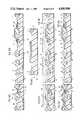
- FIGS. 16A-16C, 17, 18, and 19A-19Cillustrate the processing steps involved in etching the second polycrystalline silicon layer, the large polysilicon areas, and the intermediate oxide layer to define various control, program and floating gates;
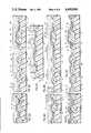
- FIGS. 20A-20Cdepict the source/drain implant step whereby self-aligned source and/or drain regions are created using the various peripheral and memory cell selection device control gates and the memory cell storage device program gates as masks;
- FIGS. 21A and 21Billustrate a high voltage phosphorous implant step designed to increase the breakdown voltage of selected peripheral devices.
- FIGS. 22A and 22Bdepict the oxidation and metallization steps employed to complete the fabrication of the memory array.
- FIG. 1specifically provides a perspective cross-sectional view of a single memory cell
- FIG. 2shows a preferred layout for a pair of mirror-image memory cells, each of which memory cells is identical to the memory cell 2 of FIG. 1.
- Memory cell 2comprises a storage device 4 and a sensing device 6 both constructed on a p-type substrate 8 of monocrystalline silicon or the like.
- Storage device 4is an electrically programmable and electrically-erasable semiconductor structure divided into sensing and programming sections 10 and 12.
- the storage deviceincludes first and second electrically conductive strips 14 and 16 separated by an interpoly oxide 18.
- the programming section 12 of storage device 4includes a floating gate portion 14R of first conductive strip 14 and a program gate portion 16R of second conductive strip 16 disposed over an active tunneling region 20 in the substrate such that floating gate portion 14R is separated from tunneling region 20 by a thin tunnel dielectric 22 formed from silicon dioxide/oxynitride (SiO 2 -Si x O y N z ) material.
- a suitable potentialis applied to the program gate portion 16R of second conductive strip 16
- charge carriersare tunneled from the substrate tunneling region 20 through thin tunnel dielectric 22 to the floating gate portion 14R of first conductive strip 14.
- the sensing section 12 of storage device 4is formed by extending the first and second conductive strips 14, 16 from programming section 12 over the surface of substrate 8 to a gate oxide 24 positioned above an active channel region 26 such that floating gate portion 14L of first conductive strip 14 and program gate portion 16L of second conductive strip 16 are verticallyaligned with gate oxide 24.
- Field oxides 28separate first conductive strip 14 from the surface of substrate 8 intermediate the thin tunnel dielectric and the gate oxide.
- Active channel region 26is bounded by diffusions 30 and 32 formed from a material having a conductivity-type opposite to that of substrate 8, i.e., a n-type material, whereupon diffusion 30 and the portion of diffusion 32 abutting active channel region 26 respectively define sensing section source/drain regions 34 and 36.
- a memory cell read line(not shown) is connected to diffusion 30 via a metal contact 38. During read operations, an indication of the presence or absence of charge carriers in first conductive strip 14 can be obtained by sensing the amount of current flow across active channel region 26 in response to reference potentials applied through metal contact 38 to source/drain region 34 and through second conductive strip 16 to program gate portion 16L.
- the selection device 6 of memory cell 2includes a third conductive strip 40 extending across an active enhancement-type channel region 42 and an active zero threshold voltage channel region 44 respectively bounded by n-type diffusions 32, 46 and 46, 48.
- Gate oxides 50 and 52respectively separate control gate portions 40L and 40R of third conductive strip 40 from channel regions 42 and 44, while field oxides 54 are interposed between the remainder of third conductive strip 40 and substrate 8.
- control gate portion 40L together with gate oxide 50 and channel region 42function as a first or enhancement mode field effect transistor structure 56 for establishing a conductive path between source/drain regions 58, 60 respectively defined by those portions of diffusions 32 and 46 abutting channel region 42
- control gate portion 40R together with gate oxide 52 and active channel region 44form a second or zero threshold voltage field effect transistor structure 62 for establishing a conductive path between source/drain regions 64, 66 respectively defined by those portions of diffusions 46 and 48 abutting channel region 44.
- a memory cell write line(not shown) is connected to diffusion 46 via metal contact 68.
- the potential present on the memory cell write lineis simultaneously transferred from metal contact 68 to the sensing section source/drain region 36 and, through diffusion 48, to tunneling region 20.
- the ability to simultaneously transfer write line potentials to source/drain region 36 and tunneling region 20permits temporary grounding of the tunneling region as well as the source/drain region 36 during memory cell read operations. Grounding of the tunneling region in turn prevents read disturb conditions from occurring in the thin tunnel dielectric 22 as memory cell 2 is being read.
- the need for establishing a direct ground line or diffusion at the source/drain region 34 of storage device sensing section 10is avoided and the bias of the sensing section can be reversed as desired, permitting the potential at source/drain region 34 to float during memory cell erase operations and eliminating any direct current path to ground through sensing section channel region 26.
- the memory cell 2is more compatible with low current power supplies.
- the zero threshold voltage characteristic of second field effect transistor structure 62 in selection device 6also enables the transfer of the true or full value of the write line potential to the tunneling region 20 during memory cell program and erase operations, whereby more efficient programming of the memory cell may be achieved.
- the fabrication of a memory array incorporating the paired memory cells of FIG. 2will now be described.
- the memory arraywhich, for purposes of convenience, is only partially illustrated in the Figures to follow, includes various peripheral devices integrally constructed with the paired memory cells on a semiconductor slice 70.
- the substrate 71 of semiconductor slice 70is a p-type substrate comprised of monocrystalline silicon or the like.
- known "front-end" processing stepsare employed in forming field implants 72 and field oxide growths 74 at selected sites on the substrate.
- an initial oxide layer 76is thermally grown to a thickness of 650 A in the areas between the field oxides 74.
- the tunneling regions 78 associated with the memory cellsare established by depositing a layer of photoresist 80 on semiconductor slice 70 and employing a masking step to define openings 82 in the photoresist layer 80 over the desired tunneling region locations.
- An oxide etchis performed to remove the portions of initial oxide layer 76 uncovered by openings 82, thus exposing selected areas of substrate 71, and an n-type impurity such as arsenic is implanted in the exposed substrate to form the tunneling regions 78.
- photoresist layer 80is stripped and a dielectric film 84 of silicon dioxide having a thickness of approximately 120A is thermally grown over tunneling regions 78.
- Dielectric film 84serves as the thin tunnel dielectric for the programming sections of the memory cell storage devices.
- dielectric film 84may be annealed at a temperature between 900° C. and 1200° C. in an ammonia-containing gaseous mixture following the thermal oxide growing step.
- the annealing processconverts the pure silicon dioxide of the dielectric film to a silicon dioxide/oxynitride (SiO 2 -Si x O y N z ) material. Because the potential barrier of silicon oxynitride to electron transport is lower than that of silicon dioxide, the use of silicon oxynitride in the thin tunneling dielectric will enhance the program and erase capabilities of the storage device programming section. As can be seen in FIG. 7, annealing of the dielectric film 84 in an ammonia-containing gaseous medium actually results in the formation of a striated structure comprising a center layer 86 of silicon dioxide covered by upper and lower layers of silicon oxynitride, respectively designated at 88 and 90.
- Additional silicon oxynitride layer 94may be formed using either deposition or sputter techniques.
- a first layer of polycrystalline silicon 96is deposited on the semiconductor slice 70 as indicated in FIGS. 8A-8C and is appropriately doped with phosphorous to establish a polycrystalline silicon sheet resistance of 20 ⁇ per square.
- the phosphorous dopingmay be carried out during the actual polycrystalline silicon deposition process or may be performed by standard diffusion or ion implantation steps occurring after deposition of the first polycrystalline silicon layer has been completed.
- An oxide layer 98is thermally grown over first polycrystalline silicon layer 96 to provide a suitable surface for receiving photoresist material.
- Photomasking techniquesare subsequently used to deposit a mask 100 of photoresist material in preparation for isolating those portions of the first polycrystalline silicon layer 96 associated with each mirror-image pair of memory cells.
- oxide layer 98 and first polycrystalline silicon layer 96are etched in alignment with photoresist mask 100 to define large polysilicon areas 102.
- photoresist mask 100is then stripped and an oxide dip-out process performed, whereby the portions of oxide layer 98 present on large polysilicon areas 102 as well as those portions of initial oxide layer 76 exposed by the etching of first polycrystalline layer 96 are removed.
- the portions of initial oxide layer 76 lying beneath the large polysilicon areasseen to best advantage in FIG. 10C, remain intact in preparation for establishing the gate oxides of the storage device sensing sections.
- FIGS. 11A and 11Billustrate the steps taken to prepare substrate 71 for the fabrication of depletion mode peripheral devices. More specifically, photomasking techniques are employed to deposit a mask 104 of photoresist material over the semiconductor slice 70. Mask 104 contains openings 106 over the substrate areas which are to support depletion mode devices. An n-type impurity such as arsenic (As) is then implanted into the substrate areas exposed by openings 106 to create depletion regions 108. It should be noted at this point that if the depletion impurity were to be implanted prior to the annealing step used during the formation of the thin tunnel dielectric 84 disclosed in connection with FIGS.
- Asarsenic
- the relatively high temperatures necessary to carry out the annealing processwould tend to drive the n-type impurity further into substrate 71.
- the depletion implantafter the thin tunnel dielectric has been annealed, however, such redistribution of the diffusion impurity can be avoided and greater control over the threshold voltage of the depletion mode peripheral devices can be exercised.
- photoresist mask 104is stripped and an intermediate oxide layer 110 having a thickness of 650 A is thermally grown over the entire surface of semiconductor slice 70.
- oxidationis carried out at a temperature of 800° C. in an environment which basically comprises oxygen and gaseous hydrochloride (HCl), producing an oxide of approximately 100 A in thickness.
- HClgaseous hydrochloride
- the oxidation temperatureis ramped up to 1,070° C. for an additional period of time to form the remaining 550 A of intermediate oxide layer 110.
- the portion of the intermediate oxide layer 110 formed at 800° C.essentially "caps" large polysilicon area 102, preventing phosphorous out-diffusion from the large polysilicon area to peripheral areas.
- the high temperature oxide growth cycle of the present inventionimparts desirable qualities such as high breakdown voltage, low surface charge and low mobile ion contamination to intermediate oxide layer 110.
- Substrate 71is prepared for the fabrication of enhancement mode devices by employing photomasking techniques to form a mask of photoresist material, indicated at 112 in FIGS. 13A and 13B, having openings 114 disposed therein for the purpose of defining peripheral device enhancement regions 116.
- Photoresist mask 112also contains openings 117 positioned as shown in FIG. 13C over those areas of the substrate on which the first field effect transistor structures of the memory cell selection devices will be fabricated.
- An enhancement implant using boron or the likeis next carried out through the intermediate oxide layer 110, whereby the threshold voltages of the various enhancement mode peripheral devices and the first field effect transistor structures may be adjusted.
- Regions 118 in substrate 71receive no implant and are consequently left in a virgin condition to provide zero threshold voltage characteristics for the second field effect transistor structures of the memory cell selection devices.
- Photoresist mask 112is thereafter stripped and another mask 119 also comprised of photoresist material is formed using the standard photomasking techniques depicted in FIGS. 14A and 14B.
- Photoresist mask 119contains openings 120 positioned over the desired location of buried contact regions in substrate 71, and those portions of intermediate oxide layer 110 uncovered by openings 120 are etched away to expose substrate 71.
- a second polycrystalline silicon layer 122is deposited on semiconductor slice 70 and oxidized to form an outer oxide layer 124.
- Second polycrystalline silicon layer 122is doped with an n-type impurity such as phosphorous, and this doping may likewise be carried out during the actual polysilicon deposition process or may be performed by standard ion implantation or impurity diffusion steps occurring between the second polycrystalline silicon layer deposition and the outer oxide layer growth steps.
- a mask 126 composed of photoresist materialis laid down over the semiconductor slice using photomasking techniques, as illustrated in FIGS. 16A-16C.
- Outer oxide layer 124 and second polycrystalline silicon layer 122are then etched in accordance with the pattern of photoresist mask 126 to define storage device program gates 128, selection device control gates 132, depletion device control gates 136, enhancement device control gates 138, and buried contacts 140 as illustrated in FIG. 17.
- Storage device program gates 128correspond to the second conductive strips 14 in FIG. 2 while selection device control gates 132 correspond to the third conductive strips 40 in FIG. 2.
- a second photoresist mask 142is laid down over the peripheral areas 144 of semiconductor slice 70, covering those segments of photoresist mask 126 located in the peripheral areas.
- the purpose of second photoresist mask 142is to protect the areas of substrate 71 surrounding the peripheral devices from damage otherwise occurring during etching of the large polysilicon area 102. With second photoresist mask 142 in place, the exposed portions of intermediate oxide layer 110 in the memory cell areas 146 of the semiconductor slice are etched away in alignment with storage device program gates 128 and selection device control gates 132, using photoresist mask 126 as a guide.
- intermediate oxide layer 110 disposed between large polysilicon area 102 and program gates 128define the interpoly oxides 148 for the memory cell storage devices, whereas the remaining portions of intermediate oxide layer 110 disposed beneath control gates 132 function as gate oxides 152 for the memory cell selection devices.
- the exposed portions of the large polysilicon area 102are next etched away to define the storage device floating gates 156, using the structures comprised of interpoly oxides 148, program gates 128, outer oxide layer 124 and photoresist mask 126 for alignment. It is evident that the presence of second photoresist mask 142 in the peripheral areas 144 of substrate slice 70 protects the substrate areas surrounding the peripheral devices from both the etchant which removes exposed portions of intermediate oxide layer 110 and the etchant which removes exposed portions of large polysilicon area 102 in the memory cell areas 146 of the semiconductor slice. However, some damage does occur to areas 160 of substrate 71 exposed after intermediate oxide layer 110 has been etched.
- damage to substrate 71 during the large polysilicon area etchcan be avoided entirely by employing an etchant such as freon 13 which discriminates between doped and undoped polycrystalline silicon.
- an etchantsuch as freon 13 which discriminates between doped and undoped polycrystalline silicon.
- large polysilicon area 102can be etched to define floating gates 156 while exposed portions 160 of substrate 71 remain unaffected by the discriminant etchant.
- second photoresist mask 142may be eliminated.
- photoresist masks 126 and 142are stripped and the remaining portions of outer oxide layer 124 as well as the now-exposed portions of the initial oxide layer 76 in the memory cell area of the semiconductor slice and the intermediate oxide layer 110 in the peripheral areas of the semiconductor slice are etched away to form the configuration illustrated in FIGS. 20A-20C.
- Those portions of initial oxide layer 76 left beneath floating gate 156 in the memory cell areasdefine gate oxides 162 for the storage device sensing sections.
- Those portions of intermediate oxide layer 110 left beneath control gates 136 and 138 in the peripheral areasdefine respective gate oxides 163 and 164 for the peripheral devices.
- n-type impuritysuch as arsenic is implanted into the various exposed areas of substrate 71 to form n-type diffusions aligned with the various program and control gates and the buried contacts.
- n-type diffusion 166serves as a buried contact region
- diffusions 168 and 170respectively serve as enhancement mode device source and drain regions
- diffusions 172 and 174respectively serve as depletion device source and drain regions
- diffusions 176, 177, 178 and 179respectively serve as source/drain regions for the second field effect transistor structures.
- diffusions 177provide conductive paths between tunneling regions 78 and channel regions 117.
- a mask composed of photoresist materialindicated at 180 in FIGS.
- 21A and 21Bmay be laid over the semiconductor slice, covering the memory cells and all but a selected few of the peripheral devices. Openings 182 in photoresist mask 180 over the selected peripheral devices expose substrate 71 to a high voltage phosphorous implant, e.g., a phosphorous implant at 50-150 kev, permitting the formation of deep impurity regions such as 184 and 186 at the selected peripheral device sites.
- a high voltage phosphorous implante.g., a phosphorous implant at 50-150 kev
- photoresist mask 180is stripped away.
- a final or refill dry oxide layer 188 of approximately 1,000 A in thicknessis then regrown over the entire semiconductor slice and a protective VapOx layer 190 is coated over the refill oxide layer 188.
- the semiconductor sliceis completed by employing several known steps including contact formation steps wherein metal contacts such as 192, 194 and 196 are positioned in predetermined patterns on the semiconductor slice.
- a semiconductor memory arrayincluding a memory cell area having individual memory cells 198 and 200 in combination with a peripheral area having enhancement mode devices 202, depletion mode devices 204 and buried contact areas 206 is thus fabricated in an integral fashion.
Landscapes
- Engineering & Computer Science (AREA)
- Manufacturing & Machinery (AREA)
- Non-Volatile Memory (AREA)
- Semiconductor Memories (AREA)
Abstract
Description
Claims (11)
Priority Applications (4)
| Application Number | Priority Date | Filing Date | Title |
|---|---|---|---|
| US06/343,845US4490900A (en) | 1982-01-29 | 1982-01-29 | Method of fabricating an MOS memory array having electrically-programmable and electrically-erasable storage devices incorporated therein |
| DE8383300451TDE3381949D1 (en) | 1982-01-29 | 1983-01-28 | METHOD FOR PRODUCING A MOS MEMORY ARRANGEMENT, WHICH CONTAINS ELECTRICALLY PROGRAMMABLE AND ELECTRICALLY ERASABLE MEMORY ELEMENTS. |
| AT83300451TATE57794T1 (en) | 1982-01-29 | 1983-01-28 | METHOD OF MANUFACTURING A MOS MEMORY ARRANGEMENT INCLUDING ELECTRICALLY PROGRAMMABLE AND ELECTRICALLY ERASABLE MEMORY ELEMENTS. |
| EP83300451AEP0085551B1 (en) | 1982-01-29 | 1983-01-28 | Method of fabricating an mos memory array having electrically-programmable and electrically-erasable storage devices incorporated therein |
Applications Claiming Priority (1)
| Application Number | Priority Date | Filing Date | Title |
|---|---|---|---|
| US06/343,845US4490900A (en) | 1982-01-29 | 1982-01-29 | Method of fabricating an MOS memory array having electrically-programmable and electrically-erasable storage devices incorporated therein |
Publications (1)
| Publication Number | Publication Date |
|---|---|
| US4490900Atrue US4490900A (en) | 1985-01-01 |
Family
ID=23347927
Family Applications (1)
| Application Number | Title | Priority Date | Filing Date |
|---|---|---|---|
| US06/343,845Expired - LifetimeUS4490900A (en) | 1982-01-29 | 1982-01-29 | Method of fabricating an MOS memory array having electrically-programmable and electrically-erasable storage devices incorporated therein |
Country Status (4)
| Country | Link |
|---|---|
| US (1) | US4490900A (en) |
| EP (1) | EP0085551B1 (en) |
| AT (1) | ATE57794T1 (en) |
| DE (1) | DE3381949D1 (en) |
Cited By (59)
| Publication number | Priority date | Publication date | Assignee | Title |
|---|---|---|---|---|
| US4577390A (en)* | 1983-02-23 | 1986-03-25 | Texas Instruments Incorporated | Fabrication of polysilicon to polysilicon capacitors with a composite dielectric layer |
| US4742492A (en)* | 1985-09-27 | 1988-05-03 | Texas Instruments Incorporated | EEPROM memory cell having improved breakdown characteristics and driving circuitry therefor |
| US4769340A (en)* | 1983-11-28 | 1988-09-06 | Exel Microelectronics, Inc. | Method for making electrically programmable memory device by doping the floating gate by implant |
| US4833096A (en)* | 1988-01-19 | 1989-05-23 | Atmel Corporation | EEPROM fabrication process |
| US4851361A (en)* | 1988-02-04 | 1989-07-25 | Atmel Corporation | Fabrication process for EEPROMS with high voltage transistors |
| US4876582A (en)* | 1983-05-02 | 1989-10-24 | Ncr Corporation | Crystallized silicon-on-insulator nonvolatile memory device |
| US4939558A (en)* | 1985-09-27 | 1990-07-03 | Texas Instruments Incorporated | EEPROM memory cell and driving circuitry |
| US4949154A (en)* | 1983-02-23 | 1990-08-14 | Texas Instruments, Incorporated | Thin dielectrics over polysilicon |
| US4962322A (en)* | 1988-12-05 | 1990-10-09 | Texas Instruments Incorporated | Nonvolatible capacitor random access memory |
| US5017979A (en)* | 1989-04-28 | 1991-05-21 | Nippondenso Co., Ltd. | EEPROM semiconductor memory device |
| US5036378A (en)* | 1989-11-01 | 1991-07-30 | At&T Bell Laboratories | Memory device |
| US5160986A (en)* | 1988-12-05 | 1992-11-03 | Sgs-Thomson Microelectronics S.R.L. | Matrix of EPROM memory cells with a tablecloth structure having an improved capacitative ratio and a process for its manufacture |
| US5196914A (en)* | 1989-03-15 | 1993-03-23 | Sgs-Thomson Microelectronics S.R.L. | Table cloth matrix of EPROM memory cells with an asymmetrical fin |
| US5268320A (en)* | 1990-12-26 | 1993-12-07 | Intel Corporation | Method of increasing the accuracy of an analog circuit employing floating gate memory devices |
| USRE34535E (en)* | 1983-02-23 | 1994-02-08 | Texas Instruments Incorporated | Floating gate memory with improved dielectric |
| US5296396A (en)* | 1988-12-05 | 1994-03-22 | Sgs-Thomson Microelectronics S.R.L. | Matrix of EPROM memory cells with a tablecloth structure having an improved capacitative ratio and a process for its manufacture |
| US5428572A (en)* | 1990-04-23 | 1995-06-27 | Kabushiki Kaisha Toshiba | Program element for use in redundancy technique for semiconductor memory device |
| US5464783A (en)* | 1993-03-24 | 1995-11-07 | At&T Corp. | Oxynitride-dioxide composite gate dielectric process for MOS manufacture |
| WO2001043177A1 (en)* | 1999-12-07 | 2001-06-14 | Advanced Micro Devices, Inc. | Method for establishing ultra-thin gate insulator using anneal in ammonia |
| US6373093B2 (en)* | 1989-04-28 | 2002-04-16 | Nippondenso Corporation | Semiconductor memory device and method of manufacturing the same |
| US20030071296A1 (en)* | 2001-10-17 | 2003-04-17 | Peng Jack Zezhong | Reprogrammable non-volatile memory using a breakdown phenomena in an ultra-thin dielectric |
| US20030073293A1 (en)* | 1998-01-09 | 2003-04-17 | Armand Ferro | In situ growth of oxide and silicon layers |
| US20030202376A1 (en)* | 2002-04-26 | 2003-10-30 | Peng Jack Zezhong | High density semiconductor memory cell and memory array using a single transistor |
| US6650143B1 (en) | 2002-07-08 | 2003-11-18 | Kilopass Technologies, Inc. | Field programmable gate array based upon transistor gate oxide breakdown |
| US6667902B2 (en) | 2001-09-18 | 2003-12-23 | Kilopass Technologies, Inc. | Semiconductor memory cell and memory array using a breakdown phenomena in an ultra-thin dielectric |
| US6671040B2 (en) | 2001-09-18 | 2003-12-30 | Kilopass Technologies, Inc. | Programming methods and circuits for semiconductor memory cell and memory array using a breakdown phenomena in an ultra-thin dielectric |
| US6709928B1 (en)* | 2001-07-31 | 2004-03-23 | Cypress Semiconductor Corporation | Semiconductor device having silicon-rich layer and method of manufacturing such a device |
| US20040125671A1 (en)* | 2002-04-26 | 2004-07-01 | Peng Jack Zezhong | High density semiconductor memory cell and memory array using a single transistor having a buried N+ connection |
| US6766960B2 (en) | 2001-10-17 | 2004-07-27 | Kilopass Technologies, Inc. | Smart card having memory using a breakdown phenomena in an ultra-thin dielectric |
| US20040156234A1 (en)* | 2002-04-26 | 2004-08-12 | Peng Jack Zezhong | High density semiconductor memory cell and memory array using a single transistor and having variable gate oxide breakdown |
| US6791891B1 (en) | 2003-04-02 | 2004-09-14 | Kilopass Technologies, Inc. | Method of testing the thin oxide of a semiconductor memory cell that uses breakdown voltage |
| US20040208055A1 (en)* | 2002-09-26 | 2004-10-21 | Jianguo Wang | Methods and circuits for testing programmability of a semiconductor memory cell and memory array using a breakdown phenomenon in an ultra-thin dielectric |
| US20040223363A1 (en)* | 2002-04-26 | 2004-11-11 | Peng Jack Zezhong | High density semiconductor memory cell and memory array using a single transistor and having counter-doped poly and buried diffusion wordline |
| US20040223370A1 (en)* | 2002-09-26 | 2004-11-11 | Jianguo Wang | Methods and circuits for programming of a semiconductor memory cell and memory array using a breakdown phenomenon in an ultra-thin dielectric |
| US20050035783A1 (en)* | 2003-08-15 | 2005-02-17 | Man Wang | Field programmable gate array |
| US20050118802A1 (en)* | 2003-12-02 | 2005-06-02 | Chang-Sheng Tsao | Method for implementing poly pre-doping in deep sub-micron process |
| US20050169040A1 (en)* | 2004-02-03 | 2005-08-04 | Peng Jack Z. | Combination field programmable gate array allowing dynamic reprogrammability |
| US20050169039A1 (en)* | 2004-02-03 | 2005-08-04 | Peng Jack Z. | Combination field programmable gate array allowing dynamic reprogrammability and non-volatile programmability based upon transistor gate oxide breakdown |
| US20050218929A1 (en)* | 2004-04-02 | 2005-10-06 | Man Wang | Field programmable gate array logic cell and its derivatives |
| US20050275427A1 (en)* | 2004-06-10 | 2005-12-15 | Man Wang | Field programmable gate array logic unit and its cluster |
| US20050275428A1 (en)* | 2004-06-10 | 2005-12-15 | Guy Schlacter | Field programmable gate array logic unit and its cluster |
| US20060062068A1 (en)* | 2004-09-20 | 2006-03-23 | Guy Schlacter | Field programmable gate arrays using both volatile and nonvolatile memory cell properties and their control |
| US20060232296A1 (en)* | 2005-04-18 | 2006-10-19 | Kilopass Technologies, Inc. | Fast processing path using field programmable gate array logic unit |
| US20060246662A1 (en)* | 2005-04-28 | 2006-11-02 | Kabushiki Kaisha Toshiba | Semiconductor device and method of manufacturing the same |
| US20080246098A1 (en)* | 2004-05-06 | 2008-10-09 | Sidense Corp. | Split-channel antifuse array architecture |
| US20080293255A1 (en)* | 2007-05-25 | 2008-11-27 | Krishnaswamy Ramkumar | Radical oxidation process for fabricating a nonvolatile charge trap memory device |
| US20090243001A1 (en)* | 2008-03-31 | 2009-10-01 | Krishnaswamy Ramkumar | Sequential deposition and anneal of a dielectic layer in a charge trapping memory device |
| US20100244115A1 (en)* | 2004-05-06 | 2010-09-30 | Sidense Corporation | Anti-fuse memory cell |
| US7898852B1 (en) | 2007-12-27 | 2011-03-01 | Cypress Semiconductor Corporation | Trapped-charge non-volatile memory with uniform multilevel programming |
| US8067284B1 (en) | 2007-05-25 | 2011-11-29 | Cypress Semiconductor Corporation | Oxynitride bilayer formed using a precursor inducing a high charge trap density in a top layer of the bilayer |
| US8643124B2 (en) | 2007-05-25 | 2014-02-04 | Cypress Semiconductor Corporation | Oxide-nitride-oxide stack having multiple oxynitride layers |
| US8685813B2 (en) | 2012-02-15 | 2014-04-01 | Cypress Semiconductor Corporation | Method of integrating a charge-trapping gate stack into a CMOS flow |
| US8735297B2 (en) | 2004-05-06 | 2014-05-27 | Sidense Corporation | Reverse optical proximity correction method |
| US8940645B2 (en) | 2007-05-25 | 2015-01-27 | Cypress Semiconductor Corporation | Radical oxidation process for fabricating a nonvolatile charge trap memory device |
| US9123572B2 (en) | 2004-05-06 | 2015-09-01 | Sidense Corporation | Anti-fuse memory cell |
| US9355849B1 (en) | 2007-05-25 | 2016-05-31 | Cypress Semiconductor Corporation | Oxide-nitride-oxide stack having multiple oxynitride layers |
| US9929240B2 (en) | 2007-05-25 | 2018-03-27 | Cypress Semiconductor Corporation | Memory transistor with multiple charge storing layers and a high work function gate electrode |
| US10374067B2 (en) | 2007-05-25 | 2019-08-06 | Longitude Flash Memory Solutions Ltd. | Oxide-nitride-oxide stack having multiple oxynitride layers |
| CN112908838A (en)* | 2019-11-19 | 2021-06-04 | 长鑫存储技术有限公司 | Method for improving pollution of heat treatment chamber |
Families Citing this family (6)
| Publication number | Priority date | Publication date | Assignee | Title |
|---|---|---|---|---|
| DE3483765D1 (en)* | 1983-09-28 | 1991-01-31 | Toshiba Kawasaki Kk | ELECTRICALLY ERASABLE AND PROGRAMMABLE NON-VOLATILE SEMICONDUCTOR MEMORY ARRANGEMENT WITH TWO GATE ELECTRODES. |
| EP0164605B1 (en)* | 1984-05-17 | 1990-02-28 | Kabushiki Kaisha Toshiba | Method of manufacturing nonvolatile semiconductor eeprom device |
| EP0215064A1 (en)* | 1985-03-08 | 1987-03-25 | Ncr Corporation | Floating gate nonvolatile field effect memory device |
| EP1111673A1 (en)* | 1995-05-10 | 2001-06-27 | STMicroelectronics S.r.l. | A method of manufacturing a MOS integrated circuit having components with different dielectrics |
| EP0782196A1 (en)* | 1995-12-28 | 1997-07-02 | STMicroelectronics S.r.l. | Method of fabricating EEPROM memory devices and EEPROM memory device so formed |
| US6518618B1 (en) | 1999-12-03 | 2003-02-11 | Intel Corporation | Integrated memory cell and method of fabrication |
Citations (11)
| Publication number | Priority date | Publication date | Assignee | Title |
|---|---|---|---|---|
| US3868187A (en)* | 1972-08-31 | 1975-02-25 | Tokyo Shibaura Electric Co | Avalanche injection type mos memory |
| US3919711A (en)* | 1973-02-26 | 1975-11-11 | Intel Corp | Erasable floating gate device |
| US3924024A (en)* | 1973-04-02 | 1975-12-02 | Ncr Co | Process for fabricating MNOS non-volatile memories |
| US4011576A (en)* | 1974-08-28 | 1977-03-08 | Tokyo Shibaura Electric Company, Ltd. | Nonvolatile semiconductor memory devices |
| JPS5232359A (en)* | 1975-09-06 | 1977-03-11 | Jiro Ishikawa | Method and apparatus for inspecting gears |
| US4016588A (en)* | 1974-12-27 | 1977-04-05 | Nippon Electric Company, Ltd. | Non-volatile semiconductor memory device |
| US4019197A (en)* | 1975-01-17 | 1977-04-19 | U.S. Philips Corporation | Semiconductor floating gate storage device with lateral electrode system |
| US4115914A (en)* | 1976-03-26 | 1978-09-26 | Hughes Aircraft Company | Electrically erasable non-volatile semiconductor memory |
| US4203158A (en)* | 1978-02-24 | 1980-05-13 | Intel Corporation | Electrically programmable and erasable MOS floating gate memory device employing tunneling and method of fabricating same |
| US4282270A (en)* | 1978-10-27 | 1981-08-04 | Fujitsu Limited | Method for forming an insulating film layer of silicon oxynitride on a semiconductor substrate surface |
| US4373249A (en)* | 1980-02-20 | 1983-02-15 | Hitachi, Ltd. | Method of manufacturing a semiconductor integrated circuit device |
Family Cites Families (2)
| Publication number | Priority date | Publication date | Assignee | Title |
|---|---|---|---|---|
| GB1540450A (en)* | 1975-10-29 | 1979-02-14 | Intel Corp | Self-aligning double polycrystalline silicon etching process |
| JPS5642375A (en)* | 1979-08-31 | 1981-04-20 | Fujitsu Ltd | Semiconductor nonvolatile memory |
- 1982
- 1982-01-29USUS06/343,845patent/US4490900A/ennot_activeExpired - Lifetime
- 1983
- 1983-01-28DEDE8383300451Tpatent/DE3381949D1/ennot_activeExpired - Lifetime
- 1983-01-28EPEP83300451Apatent/EP0085551B1/ennot_activeExpired - Lifetime
- 1983-01-28ATAT83300451Tpatent/ATE57794T1/enactive
Patent Citations (12)
| Publication number | Priority date | Publication date | Assignee | Title |
|---|---|---|---|---|
| US3868187A (en)* | 1972-08-31 | 1975-02-25 | Tokyo Shibaura Electric Co | Avalanche injection type mos memory |
| US3919711A (en)* | 1973-02-26 | 1975-11-11 | Intel Corp | Erasable floating gate device |
| US3924024A (en)* | 1973-04-02 | 1975-12-02 | Ncr Co | Process for fabricating MNOS non-volatile memories |
| US4011576A (en)* | 1974-08-28 | 1977-03-08 | Tokyo Shibaura Electric Company, Ltd. | Nonvolatile semiconductor memory devices |
| US4016588A (en)* | 1974-12-27 | 1977-04-05 | Nippon Electric Company, Ltd. | Non-volatile semiconductor memory device |
| US4019197A (en)* | 1975-01-17 | 1977-04-19 | U.S. Philips Corporation | Semiconductor floating gate storage device with lateral electrode system |
| JPS5232359A (en)* | 1975-09-06 | 1977-03-11 | Jiro Ishikawa | Method and apparatus for inspecting gears |
| US4115914A (en)* | 1976-03-26 | 1978-09-26 | Hughes Aircraft Company | Electrically erasable non-volatile semiconductor memory |
| US4203158A (en)* | 1978-02-24 | 1980-05-13 | Intel Corporation | Electrically programmable and erasable MOS floating gate memory device employing tunneling and method of fabricating same |
| US4203158B1 (en)* | 1978-02-24 | 1992-09-22 | Intel Corp | |
| US4282270A (en)* | 1978-10-27 | 1981-08-04 | Fujitsu Limited | Method for forming an insulating film layer of silicon oxynitride on a semiconductor substrate surface |
| US4373249A (en)* | 1980-02-20 | 1983-02-15 | Hitachi, Ltd. | Method of manufacturing a semiconductor integrated circuit device |
Non-Patent Citations (6)
| Title |
|---|
| Hideo Sunami, et al., "Characteristics of a Buried Channel, Graded Drain with Punch-Through Stopper (BGP) MOS Device", IEEE Electron Devices Soc., 1981 Symposium on VLSI Technology, Sep. 1981. |
| Hideo Sunami, et al., Characteristics of a Buried Channel, Graded Drain with Punch Through Stopper (BGP) MOS Device , IEEE Electron Devices Soc., 1981 Symposium on VLSI Technology, Sep. 1981.* |
| Michael F. Leahy, "Directional Plasma Etching of Polysilicon in a CF3 Cl Discharge", The Electrochemical Society, Extended Abstracts, Abstract No. 271, Oct. 1981, pp. 660-661. |
| Michael F. Leahy, Directional Plasma Etching of Polysilicon in a CF 3 Cl Discharge , The Electrochemical Society, Extended Abstracts, Abstract No. 271, Oct. 1981, pp. 660 661.* |
| Takashi Ito, et al., "Retardation of Destructive Breakdown of SiO2 Films Annealed in Ammonia Gas", J. Electrochem. Soc.: Solid-State Science and Technology, Oct. 1980, pp. 2248-2251. |
| Takashi Ito, et al., Retardation of Destructive Breakdown of SiO 2 Films Annealed in Ammonia Gas , J. Electrochem. Soc.: Solid State Science and Technology, Oct. 1980, pp. 2248 2251.* |
Cited By (116)
| Publication number | Priority date | Publication date | Assignee | Title |
|---|---|---|---|---|
| USRE34535E (en)* | 1983-02-23 | 1994-02-08 | Texas Instruments Incorporated | Floating gate memory with improved dielectric |
| US4577390A (en)* | 1983-02-23 | 1986-03-25 | Texas Instruments Incorporated | Fabrication of polysilicon to polysilicon capacitors with a composite dielectric layer |
| US4949154A (en)* | 1983-02-23 | 1990-08-14 | Texas Instruments, Incorporated | Thin dielectrics over polysilicon |
| US4876582A (en)* | 1983-05-02 | 1989-10-24 | Ncr Corporation | Crystallized silicon-on-insulator nonvolatile memory device |
| US4769340A (en)* | 1983-11-28 | 1988-09-06 | Exel Microelectronics, Inc. | Method for making electrically programmable memory device by doping the floating gate by implant |
| US4939558A (en)* | 1985-09-27 | 1990-07-03 | Texas Instruments Incorporated | EEPROM memory cell and driving circuitry |
| US4742492A (en)* | 1985-09-27 | 1988-05-03 | Texas Instruments Incorporated | EEPROM memory cell having improved breakdown characteristics and driving circuitry therefor |
| US4833096A (en)* | 1988-01-19 | 1989-05-23 | Atmel Corporation | EEPROM fabrication process |
| US4851361A (en)* | 1988-02-04 | 1989-07-25 | Atmel Corporation | Fabrication process for EEPROMS with high voltage transistors |
| US5296396A (en)* | 1988-12-05 | 1994-03-22 | Sgs-Thomson Microelectronics S.R.L. | Matrix of EPROM memory cells with a tablecloth structure having an improved capacitative ratio and a process for its manufacture |
| US4962322A (en)* | 1988-12-05 | 1990-10-09 | Texas Instruments Incorporated | Nonvolatible capacitor random access memory |
| US5723351A (en)* | 1988-12-05 | 1998-03-03 | Sgs-Thomson Microelectronics S.R.L. | Method of making matrix of EPROM memory cell with a tablecloth structure having an improved capacitative ratio |
| US5160986A (en)* | 1988-12-05 | 1992-11-03 | Sgs-Thomson Microelectronics S.R.L. | Matrix of EPROM memory cells with a tablecloth structure having an improved capacitative ratio and a process for its manufacture |
| US5475250A (en)* | 1988-12-05 | 1995-12-12 | Sgs-Thomson Microelectronics S.R.L. | Matrix of EPROM memory cells with a tablecloth structure having an improved capacitive ratio and a process for its manufacture |
| US5196914A (en)* | 1989-03-15 | 1993-03-23 | Sgs-Thomson Microelectronics S.R.L. | Table cloth matrix of EPROM memory cells with an asymmetrical fin |
| US6525400B2 (en) | 1989-04-28 | 2003-02-25 | Denso Corporation | Semiconductor memory device and method of manufacturing the same |
| US5017979A (en)* | 1989-04-28 | 1991-05-21 | Nippondenso Co., Ltd. | EEPROM semiconductor memory device |
| US6373093B2 (en)* | 1989-04-28 | 2002-04-16 | Nippondenso Corporation | Semiconductor memory device and method of manufacturing the same |
| US6365458B1 (en) | 1989-04-28 | 2002-04-02 | Nippondenso Co., Ltd. | Semiconductor memory device and method of manufacturing the same |
| US5036378A (en)* | 1989-11-01 | 1991-07-30 | At&T Bell Laboratories | Memory device |
| US5428572A (en)* | 1990-04-23 | 1995-06-27 | Kabushiki Kaisha Toshiba | Program element for use in redundancy technique for semiconductor memory device |
| US5268320A (en)* | 1990-12-26 | 1993-12-07 | Intel Corporation | Method of increasing the accuracy of an analog circuit employing floating gate memory devices |
| US5464783A (en)* | 1993-03-24 | 1995-11-07 | At&T Corp. | Oxynitride-dioxide composite gate dielectric process for MOS manufacture |
| US20040206297A1 (en)* | 1998-01-09 | 2004-10-21 | Armand Ferro | In situ growth of oxide and silicon layers |
| US8317921B2 (en) | 1998-01-09 | 2012-11-27 | Asm America, Inc. | In situ growth of oxide and silicon layers |
| US7112538B2 (en) | 1998-01-09 | 2006-09-26 | Asm America, Inc. | In situ growth of oxide and silicon layers |
| US20030073293A1 (en)* | 1998-01-09 | 2003-04-17 | Armand Ferro | In situ growth of oxide and silicon layers |
| US7105055B2 (en)* | 1998-01-09 | 2006-09-12 | Asm America, Inc. | In situ growth of oxide and silicon layers |
| US20050205010A1 (en)* | 1998-01-09 | 2005-09-22 | Armand Ferro | In situ growth of oxide and silicon layers |
| WO2001043177A1 (en)* | 1999-12-07 | 2001-06-14 | Advanced Micro Devices, Inc. | Method for establishing ultra-thin gate insulator using anneal in ammonia |
| US6444555B2 (en) | 1999-12-07 | 2002-09-03 | Advanced Micro Devices, Inc. | Method for establishing ultra-thin gate insulator using anneal in ammonia |
| US6709928B1 (en)* | 2001-07-31 | 2004-03-23 | Cypress Semiconductor Corporation | Semiconductor device having silicon-rich layer and method of manufacturing such a device |
| US20040047218A1 (en)* | 2001-09-18 | 2004-03-11 | Kilopass Technologies, Inc. | Semiconductor memory cell and memory array using a breakdown phenomena in an ultra-thin dielectric |
| US6671040B2 (en) | 2001-09-18 | 2003-12-30 | Kilopass Technologies, Inc. | Programming methods and circuits for semiconductor memory cell and memory array using a breakdown phenomena in an ultra-thin dielectric |
| US6667902B2 (en) | 2001-09-18 | 2003-12-23 | Kilopass Technologies, Inc. | Semiconductor memory cell and memory array using a breakdown phenomena in an ultra-thin dielectric |
| US6822888B2 (en) | 2001-09-18 | 2004-11-23 | Kilopass Technologies, Inc. | Semiconductor memory cell and memory array using a breakdown phenomena in an ultra-thin dielectric |
| US6798693B2 (en) | 2001-09-18 | 2004-09-28 | Kilopass Technologies, Inc. | Semiconductor memory cell and memory array using a breakdown phenomena in an ultra-thin dielectric |
| US6700151B2 (en)* | 2001-10-17 | 2004-03-02 | Kilopass Technologies, Inc. | Reprogrammable non-volatile memory using a breakdown phenomena in an ultra-thin dielectric |
| US20030071296A1 (en)* | 2001-10-17 | 2003-04-17 | Peng Jack Zezhong | Reprogrammable non-volatile memory using a breakdown phenomena in an ultra-thin dielectric |
| US6766960B2 (en) | 2001-10-17 | 2004-07-27 | Kilopass Technologies, Inc. | Smart card having memory using a breakdown phenomena in an ultra-thin dielectric |
| US6956258B2 (en) | 2001-10-17 | 2005-10-18 | Kilopass Technologies, Inc. | Reprogrammable non-volatile memory using a breakdown phenomena in an ultra-thin dielectric |
| US6940751B2 (en) | 2002-04-26 | 2005-09-06 | Kilopass Technologies, Inc. | High density semiconductor memory cell and memory array using a single transistor and having variable gate oxide breakdown |
| US6777757B2 (en) | 2002-04-26 | 2004-08-17 | Kilopass Technologies, Inc. | High density semiconductor memory cell and memory array using a single transistor |
| US20040223363A1 (en)* | 2002-04-26 | 2004-11-11 | Peng Jack Zezhong | High density semiconductor memory cell and memory array using a single transistor and having counter-doped poly and buried diffusion wordline |
| US6992925B2 (en) | 2002-04-26 | 2006-01-31 | Kilopass Technologies, Inc. | High density semiconductor memory cell and memory array using a single transistor and having counter-doped poly and buried diffusion wordline |
| US20040125671A1 (en)* | 2002-04-26 | 2004-07-01 | Peng Jack Zezhong | High density semiconductor memory cell and memory array using a single transistor having a buried N+ connection |
| US6856540B2 (en) | 2002-04-26 | 2005-02-15 | Kilopass Technologies, Inc. | High density semiconductor memory cell and memory array using a single transistor |
| US20040156234A1 (en)* | 2002-04-26 | 2004-08-12 | Peng Jack Zezhong | High density semiconductor memory cell and memory array using a single transistor and having variable gate oxide breakdown |
| US6898116B2 (en) | 2002-04-26 | 2005-05-24 | Kilopass Technologies, Inc. | High density semiconductor memory cell and memory array using a single transistor having a buried N+ connection |
| US20030202376A1 (en)* | 2002-04-26 | 2003-10-30 | Peng Jack Zezhong | High density semiconductor memory cell and memory array using a single transistor |
| US20030206467A1 (en)* | 2002-04-26 | 2003-11-06 | Peng Jack Zezhong | High density semiconductor memory cell and memory array using a single transistor |
| US6650143B1 (en) | 2002-07-08 | 2003-11-18 | Kilopass Technologies, Inc. | Field programmable gate array based upon transistor gate oxide breakdown |
| US20040208055A1 (en)* | 2002-09-26 | 2004-10-21 | Jianguo Wang | Methods and circuits for testing programmability of a semiconductor memory cell and memory array using a breakdown phenomenon in an ultra-thin dielectric |
| US7031209B2 (en) | 2002-09-26 | 2006-04-18 | Kilopass Technology, Inc. | Methods and circuits for testing programmability of a semiconductor memory cell and memory array using a breakdown phenomenon in an ultra-thin dielectric |
| US7042772B2 (en) | 2002-09-26 | 2006-05-09 | Kilopass Technology, Inc. | Methods and circuits for programming of a semiconductor memory cell and memory array using a breakdown phenomenon in an ultra-thin dielectric |
| US20040223370A1 (en)* | 2002-09-26 | 2004-11-11 | Jianguo Wang | Methods and circuits for programming of a semiconductor memory cell and memory array using a breakdown phenomenon in an ultra-thin dielectric |
| US6791891B1 (en) | 2003-04-02 | 2004-09-14 | Kilopass Technologies, Inc. | Method of testing the thin oxide of a semiconductor memory cell that uses breakdown voltage |
| US20050184754A1 (en)* | 2003-08-15 | 2005-08-25 | Kilopass Technologies, Inc. | Field programmable gate array |
| US6924664B2 (en) | 2003-08-15 | 2005-08-02 | Kilopass Technologies, Inc. | Field programmable gate array |
| US20050035783A1 (en)* | 2003-08-15 | 2005-02-17 | Man Wang | Field programmable gate array |
| US7061275B2 (en) | 2003-08-15 | 2006-06-13 | Klp International, Ltd. | Field programmable gate array |
| US6977521B2 (en) | 2003-08-15 | 2005-12-20 | Klp International, Ltd. | Field programmable gate array |
| US20060033528A1 (en)* | 2003-08-15 | 2006-02-16 | Klp International Ltd. | Field programmable gate array |
| US20050118802A1 (en)* | 2003-12-02 | 2005-06-02 | Chang-Sheng Tsao | Method for implementing poly pre-doping in deep sub-micron process |
| US6972986B2 (en) | 2004-02-03 | 2005-12-06 | Kilopass Technologies, Inc. | Combination field programmable gate array allowing dynamic reprogrammability and non-votatile programmability based upon transistor gate oxide breakdown |
| US20050169040A1 (en)* | 2004-02-03 | 2005-08-04 | Peng Jack Z. | Combination field programmable gate array allowing dynamic reprogrammability |
| US20050169039A1 (en)* | 2004-02-03 | 2005-08-04 | Peng Jack Z. | Combination field programmable gate array allowing dynamic reprogrammability and non-volatile programmability based upon transistor gate oxide breakdown |
| US7064973B2 (en) | 2004-02-03 | 2006-06-20 | Klp International, Ltd. | Combination field programmable gate array allowing dynamic reprogrammability |
| US20050218929A1 (en)* | 2004-04-02 | 2005-10-06 | Man Wang | Field programmable gate array logic cell and its derivatives |
| US20080246098A1 (en)* | 2004-05-06 | 2008-10-09 | Sidense Corp. | Split-channel antifuse array architecture |
| US8283751B2 (en) | 2004-05-06 | 2012-10-09 | Sidense Corp. | Split-channel antifuse array architecture |
| US9123572B2 (en) | 2004-05-06 | 2015-09-01 | Sidense Corporation | Anti-fuse memory cell |
| US20100244115A1 (en)* | 2004-05-06 | 2010-09-30 | Sidense Corporation | Anti-fuse memory cell |
| US8313987B2 (en) | 2004-05-06 | 2012-11-20 | Sidense Corp. | Anti-fuse memory cell |
| US8026574B2 (en) | 2004-05-06 | 2011-09-27 | Sidense Corporation | Anti-fuse memory cell |
| US8735297B2 (en) | 2004-05-06 | 2014-05-27 | Sidense Corporation | Reverse optical proximity correction method |
| US20050275428A1 (en)* | 2004-06-10 | 2005-12-15 | Guy Schlacter | Field programmable gate array logic unit and its cluster |
| US20050275427A1 (en)* | 2004-06-10 | 2005-12-15 | Man Wang | Field programmable gate array logic unit and its cluster |
| US7164290B2 (en) | 2004-06-10 | 2007-01-16 | Klp International, Ltd. | Field programmable gate array logic unit and its cluster |
| US7135886B2 (en) | 2004-09-20 | 2006-11-14 | Klp International, Ltd. | Field programmable gate arrays using both volatile and nonvolatile memory cell properties and their control |
| US20060062068A1 (en)* | 2004-09-20 | 2006-03-23 | Guy Schlacter | Field programmable gate arrays using both volatile and nonvolatile memory cell properties and their control |
| US7193436B2 (en) | 2005-04-18 | 2007-03-20 | Klp International Ltd. | Fast processing path using field programmable gate array logic units |
| US20060232296A1 (en)* | 2005-04-18 | 2006-10-19 | Kilopass Technologies, Inc. | Fast processing path using field programmable gate array logic unit |
| US7371672B2 (en)* | 2005-04-28 | 2008-05-13 | Kabushiki Kaisha Toshiba | Semiconductor device and method of manufacturing the same |
| US20060246662A1 (en)* | 2005-04-28 | 2006-11-02 | Kabushiki Kaisha Toshiba | Semiconductor device and method of manufacturing the same |
| US9929240B2 (en) | 2007-05-25 | 2018-03-27 | Cypress Semiconductor Corporation | Memory transistor with multiple charge storing layers and a high work function gate electrode |
| US10593812B2 (en) | 2007-05-25 | 2020-03-17 | Longitude Flash Memory Solutions Ltd. | Radical oxidation process for fabricating a nonvolatile charge trap memory device |
| US8283261B2 (en) | 2007-05-25 | 2012-10-09 | Cypress Semiconductor Corporation | Radical oxidation process for fabricating a nonvolatile charge trap memory device |
| US11784243B2 (en) | 2007-05-25 | 2023-10-10 | Longitude Flash Memory Solutions Ltd | Oxide-nitride-oxide stack having multiple oxynitride layers |
| US8318608B2 (en) | 2007-05-25 | 2012-11-27 | Cypress Semiconductor Corporation | Method of fabricating a nonvolatile charge trap memory device |
| US20090011609A1 (en)* | 2007-05-25 | 2009-01-08 | Krishnaswamy Ramkumar | Radical oxidation process for fabricating a nonvolatile charge trap memory device |
| US8643124B2 (en) | 2007-05-25 | 2014-02-04 | Cypress Semiconductor Corporation | Oxide-nitride-oxide stack having multiple oxynitride layers |
| US8067284B1 (en) | 2007-05-25 | 2011-11-29 | Cypress Semiconductor Corporation | Oxynitride bilayer formed using a precursor inducing a high charge trap density in a top layer of the bilayer |
| US20080293255A1 (en)* | 2007-05-25 | 2008-11-27 | Krishnaswamy Ramkumar | Radical oxidation process for fabricating a nonvolatile charge trap memory device |
| US8940645B2 (en) | 2007-05-25 | 2015-01-27 | Cypress Semiconductor Corporation | Radical oxidation process for fabricating a nonvolatile charge trap memory device |
| US8993453B1 (en) | 2007-05-25 | 2015-03-31 | Cypress Semiconductor Corporation | Method of fabricating a nonvolatile charge trap memory device |
| US20150187960A1 (en) | 2007-05-25 | 2015-07-02 | Cypress Semiconductor Corporation | Radical Oxidation Process For Fabricating A Nonvolatile Charge Trap Memory Device |
| US12009401B2 (en) | 2007-05-25 | 2024-06-11 | Longitude Flash Memory Solutions Ltd. | Memory transistor with multiple charge storing layers and a high work function gate electrode |
| US11721733B2 (en) | 2007-05-25 | 2023-08-08 | Longitude Flash Memory Solutions Ltd. | Memory transistor with multiple charge storing layers and a high work function gate electrode |
| US11456365B2 (en) | 2007-05-25 | 2022-09-27 | Longitude Flash Memory Solutions Ltd. | Memory transistor with multiple charge storing layers and a high work function gate electrode |
| US9355849B1 (en) | 2007-05-25 | 2016-05-31 | Cypress Semiconductor Corporation | Oxide-nitride-oxide stack having multiple oxynitride layers |
| US10312336B2 (en) | 2007-05-25 | 2019-06-04 | Cypress Semiconductor Corporation | Memory transistor with multiple charge storing layers and a high work function gate electrode |
| US10374067B2 (en) | 2007-05-25 | 2019-08-06 | Longitude Flash Memory Solutions Ltd. | Oxide-nitride-oxide stack having multiple oxynitride layers |
| US10446656B2 (en) | 2007-05-25 | 2019-10-15 | Longitude Flash Memory Solutions Ltd. | Memory transistor with multiple charge storing layers and a high work function gate electrode |
| US10304968B2 (en) | 2007-05-25 | 2019-05-28 | Cypress Semiconductor Corporation | Radical oxidation process for fabricating a nonvolatile charge trap memory device |
| US10896973B2 (en) | 2007-05-25 | 2021-01-19 | Longitude Flash Memory Solutions Ltd. | Oxide-nitride-oxide stack having multiple oxynitride layers |
| US10903342B2 (en) | 2007-05-25 | 2021-01-26 | Longitude Flash Memory Solutions Ltd. | Oxide-nitride-oxide stack having multiple oxynitride layers |
| US10903068B2 (en) | 2007-05-25 | 2021-01-26 | Longitude Flash Memory Solutions Ltd. | Oxide-nitride-oxide stack having multiple oxynitride layers |
| US12266521B2 (en) | 2007-05-25 | 2025-04-01 | Longitude Flash Memory Solutions Ltd. | Oxide-nitride-oxide stack having multiple oxynitride layers |
| US11056565B2 (en) | 2007-05-25 | 2021-07-06 | Longitude Flash Memory Solutions Ltd. | Flash memory device and method |
| US11222965B2 (en) | 2007-05-25 | 2022-01-11 | Longitude Flash Memory Solutions Ltd | Oxide-nitride-oxide stack having multiple oxynitride layers |
| US7898852B1 (en) | 2007-12-27 | 2011-03-01 | Cypress Semiconductor Corporation | Trapped-charge non-volatile memory with uniform multilevel programming |
| US8088683B2 (en) | 2008-03-31 | 2012-01-03 | Cypress Semiconductor Corporation | Sequential deposition and anneal of a dielectic layer in a charge trapping memory device |
| US20090243001A1 (en)* | 2008-03-31 | 2009-10-01 | Krishnaswamy Ramkumar | Sequential deposition and anneal of a dielectic layer in a charge trapping memory device |
| US8685813B2 (en) | 2012-02-15 | 2014-04-01 | Cypress Semiconductor Corporation | Method of integrating a charge-trapping gate stack into a CMOS flow |
| CN112908838A (en)* | 2019-11-19 | 2021-06-04 | 长鑫存储技术有限公司 | Method for improving pollution of heat treatment chamber |
Also Published As
| Publication number | Publication date |
|---|---|
| EP0085551A2 (en) | 1983-08-10 |
| DE3381949D1 (en) | 1990-11-29 |
| EP0085551A3 (en) | 1986-06-04 |
| EP0085551B1 (en) | 1990-10-24 |
| ATE57794T1 (en) | 1990-11-15 |
Similar Documents
| Publication | Publication Date | Title |
|---|---|---|
| US4490900A (en) | Method of fabricating an MOS memory array having electrically-programmable and electrically-erasable storage devices incorporated therein | |
| US5086325A (en) | Narrow width EEPROM with single diffusion electrode formation | |
| US5094968A (en) | Fabricating a narrow width EEPROM with single diffusion electrode formation | |
| US4701776A (en) | MOS floating gate memory cell and process for fabricating same | |
| US4822750A (en) | MOS floating gate memory cell containing tunneling diffusion region in contact with drain and extending under edges of field oxide | |
| US6351017B1 (en) | High voltage transistor with modified field implant mask | |
| EP0699344B1 (en) | EEPROM memory cell | |
| US5019879A (en) | Electrically-flash-erasable and electrically-programmable memory storage devices with self aligned tunnel dielectric area | |
| US20020086482A1 (en) | Method and structure for an improved floating gate memory cell | |
| JPH06112501A (en) | Nonvolatile semiconductor memory device and manufacturing method thereof | |
| US20020182807A1 (en) | Semiconductor device and method of manufacturing same | |
| US4398338A (en) | Fabrication of high speed, nonvolatile, electrically erasable memory cell and system utilizing selective masking, deposition and etching techniques | |
| JP3241330B2 (en) | Flash memory and manufacturing method thereof | |
| EP0573728B1 (en) | Process for fabricating high density contactless EPROMs | |
| US5851879A (en) | Method for fabricating compact contactless trenched flash memory cell | |
| US6043122A (en) | Three-dimensional non-volatile memory | |
| EP0160003B1 (en) | Mos floating gate memory cell and process for fabricating same | |
| US5656845A (en) | EEPROM on insulator | |
| EP0373698B1 (en) | Selective asperity definition technique suitable for use in fabricating floating-gate transistor | |
| US5140551A (en) | Non-volatile dynamic random access memory array and the method of fabricating thereof | |
| JP2910673B2 (en) | Nonvolatile semiconductor memory device and method of manufacturing the same | |
| US20030052361A1 (en) | Triple self-aligned split-gate non-volatile memory device | |
| CA2484739A1 (en) | Ultra small thin windows in floating gate transistors defined by lost nitride spacers | |
| US5904524A (en) | Method of making scalable tunnel oxide window with no isolation edges | |
| US5565371A (en) | Method of making EPROM with separate erasing and programming regions |
Legal Events
| Date | Code | Title | Description |
|---|---|---|---|
| AS | Assignment | Owner name:SEEQ TECHNOLOGY, INC., 2001 FORTUNE DRIVE, SAN JOS Free format text:ASSIGNMENT OF ASSIGNORS INTEREST.;ASSIGNOR:CHIU, TE-LONG;REEL/FRAME:003967/0148 Effective date:19820319 | |
| FEPP | Fee payment procedure | Free format text:PAYOR NUMBER ASSIGNED (ORIGINAL EVENT CODE: ASPN); ENTITY STATUS OF PATENT OWNER: LARGE ENTITY | |
| FPAY | Fee payment | Year of fee payment:4 | |
| REIN | Reinstatement after maintenance fee payment confirmed | ||
| AS | Assignment | Owner name:SILICON VALLEY BANK, CALIFORNIA Free format text:ASSIGNMENT OF ASSIGNORS INTEREST.;ASSIGNOR:SEEQ TECHNOLOGY, INCORPORATED;REEL/FRAME:006441/0970 Effective date:19921124 | |
| FP | Lapsed due to failure to pay maintenance fee | Effective date:19930103 | |
| AS | Assignment | Owner name:SEEQ TECHNOLOGY, INCORPORATED, CALIFORNIA Free format text:RELEASE BY SECURED PARTY;ASSIGNOR:SILICON VALLEY BANK;REEL/FRAME:006797/0240 Effective date:19930224 | |
| FEPP | Fee payment procedure | Free format text:PETITION RELATED TO MAINTENANCE FEES FILED (ORIGINAL EVENT CODE: PMFP); ENTITY STATUS OF PATENT OWNER: LARGE ENTITY | |
| AS | Assignment | Owner name:CIT GROUP/CREDIT FINANCING, INC., THE, CALIFORNIA Free format text:SECURITY INTEREST;ASSIGNOR:SEEQ TECHNOLOGY INCORPORATED;REEL/FRAME:006763/0733 Effective date:19931122 | |
| FEPP | Fee payment procedure | Free format text:PETITION RELATED TO MAINTENANCE FEES GRANTED (ORIGINAL EVENT CODE: PMFG); ENTITY STATUS OF PATENT OWNER: LARGE ENTITY | |
| AS | Assignment | Owner name:ATMEL CORPORATION, CALIFORNIA Free format text:ASSIGNMENT OF ASSIGNORS INTEREST;ASSIGNOR:SEEQ TECHNOLOGY INCORPORATED;REEL/FRAME:006863/0773 Effective date:19940207 | |
| AS | Assignment | Owner name:SEEQ TECHNOLOGY INCORPORATED, CALIFORNIA Free format text:PARTIAL RELEASE OF SECURITY INTEREST;ASSIGNOR:CIT GROUP/CREDIT FINANCE, INC., THE;REEL/FRAME:006994/0849 Effective date:19940304 Owner name:ATMEL CORPORATION, CALIFORNIA Free format text:ASSIGNMENT OF ASSIGNORS INTEREST;ASSIGNOR:SEEQ TECHNOLOGY INCORPORATED;REEL/FRAME:006975/0106 Effective date:19940419 | |
| FPAY | Fee payment | Year of fee payment:8 | |
| SULP | Surcharge for late payment | ||
| STCF | Information on status: patent grant | Free format text:PATENTED CASE | |
| DP | Notification of acceptance of delayed payment of maintenance fee | ||
| FEPP | Fee payment procedure | Free format text:PAYER NUMBER DE-ASSIGNED (ORIGINAL EVENT CODE: RMPN); ENTITY STATUS OF PATENT OWNER: LARGE ENTITY Free format text:PAYOR NUMBER ASSIGNED (ORIGINAL EVENT CODE: ASPN); ENTITY STATUS OF PATENT OWNER: LARGE ENTITY | |
| FPAY | Fee payment | Year of fee payment:12 | |
| AS | Assignment | Owner name:ATMEL CORPORATION, CALIFORNIA Free format text:ASSIGNMENT OF ASSIGNORS INTEREST;ASSIGNOR:ATMEL CORPORATION;REEL/FRAME:010231/0283 Effective date:19990913 |