US4490576A - Connector for use with jacketed metal clad cable - Google Patents
Connector for use with jacketed metal clad cableDownload PDFInfo
- Publication number
- US4490576A US4490576AUS06/291,444US29144481AUS4490576AUS 4490576 AUS4490576 AUS 4490576AUS 29144481 AUS29144481 AUS 29144481AUS 4490576 AUS4490576 AUS 4490576A
- Authority
- US
- United States
- Prior art keywords
- cable
- connector
- diameter
- fingers
- metal clad
- Prior art date
- Legal status (The legal status is an assumption and is not a legal conclusion. Google has not performed a legal analysis and makes no representation as to the accuracy of the status listed.)
- Expired - Lifetime
Links
Images
Classifications
- H—ELECTRICITY
- H02—GENERATION; CONVERSION OR DISTRIBUTION OF ELECTRIC POWER
- H02G—INSTALLATION OF ELECTRIC CABLES OR LINES, OR OF COMBINED OPTICAL AND ELECTRIC CABLES OR LINES
- H02G3/00—Installations of electric cables or lines or protective tubing therefor in or on buildings, equivalent structures or vehicles
- H02G3/02—Details
- H02G3/06—Joints for connecting lengths of protective tubing or channels, to each other or to casings, e.g. to distribution boxes; Ensuring electrical continuity in the joint
- H02G3/0616—Joints for connecting tubing to casing
Definitions
- One relatively new type of electrical cable now gaining increasing popularity and acceptancecomprises a flexible metallic tube entirely covered with a layer of plastic or other elastomeric material.
- Some manufacturers of these cablesfabricate the tubular metallic core from helical windings making it similar to "BX" cable, while others flute a metallic tube annularly along its length similar to the manner of forming hydroformed bellows. These configurations provide the cable with a degree of flexibility.
- At least several connectorshave appeared on the market which are designed specifically for connecting this type of cable to an electrical box. Each of these includes at least one compromise somewhere in its design that either unduly increases its cost, limits its use to a narrow range of cable size, or requires an unnecessarily long installation time.
- An effective connector for this type of cableshould preferrably be capable of assembly quickly and easily both to the cable and to an electrical box, accomodate a relatively wide range of cable sizes, provide a solid electrical grounding connection between the metal portions of the cable and the electrical box, and in some applications provide a reasonable seal between the inside of the box and the outside environment.
- the connector of this invention(which will be described in greater detail later) includes a tubular connector body and a connector nut, both of which are external and visible parts, and internally it includes a retainer element, a rubber bushing and an anti-friction washer.
- the retainer elementhas the shape of a thin, narrow-rim washer with a plurality of integrally formed fingers or prongs extending radially inwardly which are formed or bent somewhat toward the electrical box end of the connector. Each of these fingers terminates short of the center of the washer so that, cumulatively, they form a central opening which is deliberately smaller than the diameter of the metallic portions of the cable.
- the outer plastic coatingis stripped from its end to expose these metallic portions for direct attachment of the connector thereto.
- these fingers in the connector assemblymust be properly designed to permit a given size cable from any manufacturer to pass through the center hole of the retainer element and deflect the fingers thereon when the cable is moving therethrough in the direction of the electrical box. But, because these fingers are bent toward the electrical box to begin with, any attempt to pull the cable in the opposite direction away from the electrical box causes the fingers to dig or bite into the cable and prevent its removal.
- the retaining elementis preferrably staked or swaged in place within the tubular connector body so as to always be fixed and properly oriented for use, it would also work if not affixed to the connector body, although perhaps not with a comparable grounding integrity.
- the ease and simplicity of attaching the cable to the connectoris further enhanced by appropriately sizing the parts such that the entire connector assembly can be shipped in assembled form with the connector nut drawn up on the connector body by hand.
- a further tightening of this connector nutcauses a radial contraction of the rubber grommet to produce an inner diameter which would interfere with the free entry therethrough of the cable.
- the installer of the connectorneed only properly prepare the end of the cable (in accordance with directions supplied) and push it through the connector to lock the connector and the cable together. Then, simply by tightening down on the connector nut with an appropriate tool, the connector is further locked onto the cable and an effective sealed connection has also been made.
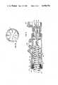
- FIG. 1is a longitudinal cross-sectional view of a connector assembly embodying the elements of the present invention, this view including a segment of jacketed, metal clad cable secured therein so as to show the relationship between the connector and a cable connected thereby.
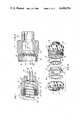
- FIG. 2is an exploded perspective view of the connector shown in FIG. 1.
- FIG. 3is a cross-sectional view of the connector body subassembly with the retainer element in place and locked therein.
- FIG. 4is an end view of the retainer element showing the relative size and configuration of the outer annular rim portion and the individual fingers.
- FIG. 5is a cross-sectional view of the connector with a slightly modified body portion for explosion-proof applications.
- Connector assembly 10including a connector body 12, a retainer element 14, a connector nut 16, a grommet 18 and a washer 20.
- Connector assembly 10is used to connect a length of metal clad cable shown generally at 30 to an electrical box (not shown) in a conventional manner.
- Cable 30includes a fluted metallic portion 32 that protectively covers and shields a plurality of conductors 34, 35 and 36.
- Metallic portions 32 of the cableare coated or covered with a significant layer of plastic or other elastomeric material 38.
- connector body 12is generally tubular in shape with a large external thread 40 at its outermost end, a smaller external thread 42 at its innermost or electrical box end, and a portion 44 therebetween having a generally hexagonally shaped outer configuration which can be grasped by a wrench or equivalent tool.
- the connector body 12has four concentric diameters which get progressively smaller from the outer end to the inner, electrical-box end.
- the largest diameter internal surface 50is at the outer end inside threads 40, and it steps down to a slightly smaller diameter surface 52 which is quite short axially and which ends at an outwardly facing shoulder 54. From shoulder 54 the inner surface of the connector body slopes to a smaller diameter surface 56 that is preferrably larger then the diameter of the metallic portions 32 of cable 30.
- Diameter 56then slopes along surface 57 down to the smallest diameter surface 58 which deliberately has a smaller diameter than the metallic portion 32 of cable 30 so that it cannot pass therethrough. However, this smallest diameter internal surface 58 is sufficiently large to permit all of the cables 34-36 to pass therebetween and into the interior of an electrical box.
- retainer element 14could be carried loosely inside surface 52, preferrably it is either pressed into that surface by way of an interferance fit or, as shown here, it is loosely set against shoulder 54 and staked in place.
- the outer diameter of retainer element 14is slightly smaller than the diameter of surface 52, and a swaging tool (not shown) having portions larger in diameter than the diameter of surface 52 and smaller than the diameter of surface 50 is used to upset portions 59 of surface 52 and drive them against retainer element 14 to lock it against shoulder 54.
- Retainer element 14is preferrably formed either from spring temper sheet metal or it is later heat treated, and it has a thin outer rim or annulus 60 (see FIG. 4) with a plurality of at least five radially inwardly projecting fingers or prongs 62, here being shown specifically as eight in number. Fingers 62 are each about three times as long as they are wide, and they are bent away from the plane of annulus 60 toward the inner end of the connector at an angle of approximately 35°, although satisfactory results could be achieved with angles up to about 55°. The distal ends of all of the fingers 62 terminate on the circumference of an imaginary circle which is smaller in diameter then the smallest possible diameter of the metallic portions 32 of a given nominal size of cable 30.
- Connector nut 16has a generally hexagonal outer configuration and an internal thread 64 therein.
- the outermost end 66 of connector nut 16is turned radially inwardly to form a flange and define both the nuts minimum diameter surface 67 and an inwardly facing shoulder 68.
- Grommet 18is of generally tubular shape and is molded of rubber or some other desirable elastomer. Referring specifically to FIG. 2, it includes an outermost end surface 70, major and minor outer diameters 71 and 72 (respectively) joined by an intermediary tapered surface 74, and also an innermost end surface 75. An axial hole 76 extends therethrough which is of a free or undeformed diameter slightly greater than the outer diameter of the plastic covering 38 of the largest cable 30 intended to be used with the connector. Minor outer diameter 72 fits loosely inside surface 50 of the connector body, and tapered surface 74 abuts a chamfer 78 at the outermost edge of the connector body when originally assembled and prior to the final tightening of the connector nut that clamps the cable in place.
- Washer 20comprises anti-friction means, is preferrably constructed of some low friction material such as Teflon, has an outer diameter slightly larger than the outer diameter of grommet 18, and it's inner diameter is slightly larger than the inner diameter of grommet 18.
- washer 20is positioned between shoulder 68 on the connector nut and grommet surface 71.
- the connector body subassemblyis assembled by first dropping retainer element 14 into the outer end of connector body 12 such that it lies against shoulder 54 with its fingers 62 slanting inwardly toward the electrical box end of the connector body.
- a staking toolis driven into the outer end of the connector body 12 to upset some of the material forming inner surface 52 and thereby fix retainer element 14 in that position.
- Compression grommet 18 and antifriction washer 20are dropped into connector nut 16, and then connector nut 16 is screwed up on threads 40 by hand until resistance is felt. The connector assembly is then shipped in this condition.
- a final assemblyinvolves stripping a designated length of the outer plastic coating 38 from cable 30 so as to expose a proper length of metallic portions 32, pushing this prepared end of cable 30 into the outer end of connector assembly 10 until the exposed edge of metallic portions 32 abuts internal surface 57 inside the connector body, and then tightening nut 16 until all threads are taken up and its leading edge abuts the connector body.
- nut 16rotates, it moves compression grommet 18 toward the inner end of the connector causing it to be compressed radially inwardly so as to squeeze the plastic jacket 38 of the cable to both hold the cable 30 and seal it relative to the connector assembly.
- Anti-friction washer 20avoids direct contact between the driving surface 68 of the connector nut and the outer surface 71 of the compression grommet 18. This minimizes resistive torque on the nut and permits the grommet 18 and cable 30 to move axially to the right without twisting.
- FIG. 5shows a connector assembly designated generally 80 having a modified connector body 82 for use in conjunction with explosion-proof applications where explosion-proof seals are required.
- the inner threaded end 83 of connector assembly 80is screwed into a standard potting fitting 84.
- Potting fitting 84has various side openings for introducing sealing material therein (as is well known in the art), and it is conventionally located between assembly 80 and some form of electrical box 86 or the like.
- Retainer element 14, connector nut 16, compression grommet 18 and anti-friction washer 20are identical with the elements shown in FIGS. 1-4 and thus carry the same identification numbers.
- the connector body 82The principal difference lies in the connector body 82, and it will be noted that the inner end of that body includes a relatively large external thread 85 which permits a large diameter internal hole 86 to extend through that end of the connector, its diameter being larger than that of the metallic portions of cable 30.
- metallic portions 32 of cable 30have been stripped of their plastic jacket 38 over a longer span than in the earlier embodiment which permits a longer segment of cable to be pushed through the connector assembly 80. This is desirable so that the stripped end of metallic portions 32 locate inside potting fitting 84 so that they can be properly and thoroughly sealed with potting compound according to well known practice.
Landscapes
- Engineering & Computer Science (AREA)
- Architecture (AREA)
- Civil Engineering (AREA)
- Structural Engineering (AREA)
- Details Of Connecting Devices For Male And Female Coupling (AREA)
- Connector Housings Or Holding Contact Members (AREA)
Abstract
Description
Claims (4)
Priority Applications (1)
| Application Number | Priority Date | Filing Date | Title |
|---|---|---|---|
| US06/291,444US4490576A (en) | 1981-08-10 | 1981-08-10 | Connector for use with jacketed metal clad cable |
Applications Claiming Priority (1)
| Application Number | Priority Date | Filing Date | Title |
|---|---|---|---|
| US06/291,444US4490576A (en) | 1981-08-10 | 1981-08-10 | Connector for use with jacketed metal clad cable |
Publications (1)
| Publication Number | Publication Date |
|---|---|
| US4490576Atrue US4490576A (en) | 1984-12-25 |
Family
ID=23120311
Family Applications (1)
| Application Number | Title | Priority Date | Filing Date |
|---|---|---|---|
| US06/291,444Expired - LifetimeUS4490576A (en) | 1981-08-10 | 1981-08-10 | Connector for use with jacketed metal clad cable |
Country Status (1)
| Country | Link |
|---|---|
| US (1) | US4490576A (en) |
Cited By (98)
| Publication number | Priority date | Publication date | Assignee | Title |
|---|---|---|---|---|
| US4549755A (en)* | 1983-06-16 | 1985-10-29 | Efcor, Inc. | Armored cable connector |
| US4686738A (en)* | 1984-09-26 | 1987-08-18 | Elektro-Bladh Ab | Cable lead-in device |
| US4885429A (en)* | 1989-01-10 | 1989-12-05 | Hubbell Incorporated | Metal clad cable connector |
| US5059747A (en)* | 1989-12-08 | 1991-10-22 | Thomas & Betts Corporation | Connector for use with metal clad cable |
| US5208427A (en)* | 1992-01-31 | 1993-05-04 | Thomas & Betts Corporation | Connector for terminating electrical cable assemblies of multiple configurations |
| US5321205A (en)* | 1993-01-15 | 1994-06-14 | Thomas & Betts Corporation | Electrical connector fitting |
| US5374785A (en)* | 1993-01-26 | 1994-12-20 | Thomas & Betts Corporation | Hub locknut |
| HRP931034A2 (en)* | 1993-07-09 | 1995-02-28 | Nenad Marinović | Adapter for a cable direct entry into a flameproof enclosure |
| WO1998036481A1 (en)* | 1997-02-13 | 1998-08-20 | Heyco Products, Inc. | 90° sealing nut |
| US5872335A (en)* | 1997-06-30 | 1999-02-16 | Heyco Products, Inc. | 90 degree sealing nut |
| US5931516A (en)* | 1998-01-06 | 1999-08-03 | Southco, Inc. | Swell latch assembly |
| US5931695A (en)* | 1997-12-17 | 1999-08-03 | The Whitaker Corporation | Retaining nut |
| US5957508A (en)* | 1996-08-16 | 1999-09-28 | Robert Bosch Gmbh | Sealing device |
| US5977486A (en)* | 1997-12-11 | 1999-11-02 | Sumitomo Wiring Systems, Ltd. | Grommet assembly and method of attaching same to a vehicle |
| US6162995A (en)* | 1992-04-27 | 2000-12-19 | General Llc | Armored electrical cable connector |
| US6194659B1 (en)* | 1997-05-14 | 2001-02-27 | Legrand | Cable entry device |
| US6300569B1 (en) | 1997-02-13 | 2001-10-09 | Heyco Products, Inc. | 90° sealing nut |
| US6444907B1 (en) | 2001-05-01 | 2002-09-03 | Bridgeport Fittings, Inc. | Electrical cable connector |
| US20020134573A1 (en)* | 2001-03-22 | 2002-09-26 | Scott Christman | Connector assembly for armored cable |
| US6464266B1 (en) | 1998-12-18 | 2002-10-15 | Accor Technology, Inc. | Tube coupling |
| US6510311B1 (en)* | 1999-07-08 | 2003-01-21 | Robert N. Stitt | Phone amplification and privacy device |
| US20030226939A1 (en)* | 2002-06-07 | 2003-12-11 | Beck Jeremy M. | Grommet connector |
| US6691936B2 (en)* | 2000-08-21 | 2004-02-17 | Volvo Lastvagnar Ab | Needle position sensing device |
| US20040094951A1 (en)* | 2002-11-04 | 2004-05-20 | Sigrist Peter C. | Conduit sealing system |
| US20050127247A1 (en)* | 2003-12-16 | 2005-06-16 | Seymour Douglas G. | Bracket assembly |
| US20060141829A1 (en)* | 2004-12-29 | 2006-06-29 | Remke Industries, Inc. | Electrical cable connector with grounding insert |
| US20070013149A1 (en)* | 2005-07-12 | 2007-01-18 | Bobby Hu | Retaining assembly |
| US7304251B1 (en)* | 2005-12-15 | 2007-12-04 | Arlington Industries, Inc. | Electrical fitting for snap in connection of cables |
| US20090211806A1 (en)* | 2008-02-26 | 2009-08-27 | H-Tech, Llc | Electronic assembly including rf feedthrough connector and related methods |
| US20100194098A1 (en)* | 2009-02-03 | 2010-08-05 | Hennemann Thomas L | Push Lock Pipe Connection System |
| US20100194104A1 (en)* | 2009-02-03 | 2010-08-05 | Hennemann Thomas L | Male push lock pipe connection system |
| US20100295252A1 (en)* | 2009-05-20 | 2010-11-25 | Freudenberg-Nok General Partnership | Two-Piece Valve Stem Seal |
| US7841630B1 (en)* | 2007-09-19 | 2010-11-30 | Bridgeport Fittings, Inc. | Electric metal tube push-in fitting |
| US20110012339A1 (en)* | 2009-02-03 | 2011-01-20 | Hennemann Thomas L | Push Lock Pipe Connection System and Disconnection Tool |
| US8287320B2 (en) | 2009-05-22 | 2012-10-16 | John Mezzalingua Associates, Inc. | Coaxial cable connector having electrical continuity member |
| US8313345B2 (en) | 2009-04-02 | 2012-11-20 | John Mezzalingua Associates, Inc. | Coaxial cable continuity connector |
| US8323053B2 (en) | 2010-10-18 | 2012-12-04 | John Mezzalingua Associates, Inc. | Connector having a constant contact nut |
| US8337229B2 (en) | 2010-11-11 | 2012-12-25 | John Mezzalingua Associates, Inc. | Connector having a nut-body continuity element and method of use thereof |
| US8366481B2 (en) | 2011-03-30 | 2013-02-05 | John Mezzalingua Associates, Inc. | Continuity maintaining biasing member |
| US8382517B2 (en) | 2010-10-18 | 2013-02-26 | John Mezzalingua Associates, Inc. | Dielectric sealing member and method of use thereof |
| US8388377B2 (en) | 2011-04-01 | 2013-03-05 | John Mezzalingua Associates, Inc. | Slide actuated coaxial cable connector |
| US8398421B2 (en) | 2011-02-01 | 2013-03-19 | John Mezzalingua Associates, Inc. | Connector having a dielectric seal and method of use thereof |
| US8414322B2 (en) | 2010-12-14 | 2013-04-09 | Ppc Broadband, Inc. | Push-on CATV port terminator |
| US8444445B2 (en) | 2009-05-22 | 2013-05-21 | Ppc Broadband, Inc. | Coaxial cable connector having electrical continuity member |
| US8465322B2 (en) | 2011-03-25 | 2013-06-18 | Ppc Broadband, Inc. | Coaxial cable connector |
| US8469739B2 (en) | 2011-02-08 | 2013-06-25 | Belden Inc. | Cable connector with biasing element |
| US8506325B2 (en) | 2008-09-30 | 2013-08-13 | Belden Inc. | Cable connector having a biasing element |
| US8573996B2 (en) | 2009-05-22 | 2013-11-05 | Ppc Broadband, Inc. | Coaxial cable connector having electrical continuity member |
| US8591244B2 (en) | 2011-07-08 | 2013-11-26 | Ppc Broadband, Inc. | Cable connector |
| US8737043B2 (en) | 2011-03-10 | 2014-05-27 | Ericson Manufacturing Co. | Electrical enclosure |
| US8753147B2 (en) | 2011-06-10 | 2014-06-17 | Ppc Broadband, Inc. | Connector having a coupling member for locking onto a port and maintaining electrical continuity |
| US8766109B2 (en) | 2011-06-27 | 2014-07-01 | Thomas & Betts International, Inc. | Cable connector with bushing element |
| US8814596B2 (en) | 2010-09-17 | 2014-08-26 | Roxtec Ab | Modular connector for cables or pipes and system comprising such modular connector |
| US8888526B2 (en) | 2010-08-10 | 2014-11-18 | Corning Gilbert, Inc. | Coaxial cable connector with radio frequency interference and grounding shield |
| US8910980B2 (en) | 2011-11-08 | 2014-12-16 | Thomas & Betts International, Inc. | Liquid-tight fitting |
| US20150014054A1 (en)* | 2009-08-21 | 2015-01-15 | Cmp Products Limited | Filler Assembly for Cable Gland |
| US9017101B2 (en) | 2011-03-30 | 2015-04-28 | Ppc Broadband, Inc. | Continuity maintaining biasing member |
| US9048599B2 (en) | 2013-10-28 | 2015-06-02 | Corning Gilbert Inc. | Coaxial cable connector having a gripping member with a notch and disposed inside a shell |
| US9071019B2 (en) | 2010-10-27 | 2015-06-30 | Corning Gilbert, Inc. | Push-on cable connector with a coupler and retention and release mechanism |
| US9136654B2 (en) | 2012-01-05 | 2015-09-15 | Corning Gilbert, Inc. | Quick mount connector for a coaxial cable |
| US9147963B2 (en) | 2012-11-29 | 2015-09-29 | Corning Gilbert Inc. | Hardline coaxial connector with a locking ferrule |
| US9147955B2 (en) | 2011-11-02 | 2015-09-29 | Ppc Broadband, Inc. | Continuity providing port |
| US9153911B2 (en) | 2013-02-19 | 2015-10-06 | Corning Gilbert Inc. | Coaxial cable continuity connector |
| US9166348B2 (en) | 2010-04-13 | 2015-10-20 | Corning Gilbert Inc. | Coaxial connector with inhibited ingress and improved grounding |
| US9172154B2 (en) | 2013-03-15 | 2015-10-27 | Corning Gilbert Inc. | Coaxial cable connector with integral RFI protection |
| US9190744B2 (en) | 2011-09-14 | 2015-11-17 | Corning Optical Communications Rf Llc | Coaxial cable connector with radio frequency interference and grounding shield |
| US9203167B2 (en) | 2011-05-26 | 2015-12-01 | Ppc Broadband, Inc. | Coaxial cable connector with conductive seal |
| US20150372469A1 (en)* | 2014-06-24 | 2015-12-24 | Lear Corporation | Cordset Assembly |
| WO2016018865A1 (en)* | 2014-07-28 | 2016-02-04 | Wal-Mart Stores, Inc. | Apparatus and method for assembling an electrical whip |
| US9287659B2 (en) | 2012-10-16 | 2016-03-15 | Corning Optical Communications Rf Llc | Coaxial cable connector with integral RFI protection |
| US9312611B2 (en) | 2004-11-24 | 2016-04-12 | Ppc Broadband, Inc. | Connector having a conductively coated member and method of use thereof |
| US9371948B2 (en) | 2013-08-14 | 2016-06-21 | Heyco, Inc. | Liquid-tight connector |
| US9407016B2 (en) | 2012-02-22 | 2016-08-02 | Corning Optical Communications Rf Llc | Coaxial cable connector with integral continuity contacting portion |
| WO2016134457A1 (en)* | 2015-02-24 | 2016-09-01 | Tm4 Inc. | Sealing grommet assembly and installation method therefor |
| US9525220B1 (en) | 2015-11-25 | 2016-12-20 | Corning Optical Communications LLC | Coaxial cable connector |
| US9548557B2 (en) | 2013-06-26 | 2017-01-17 | Corning Optical Communications LLC | Connector assemblies and methods of manufacture |
| US9548572B2 (en) | 2014-11-03 | 2017-01-17 | Corning Optical Communications LLC | Coaxial cable connector having a coupler and a post with a contacting portion and a shoulder |
| US9570845B2 (en) | 2009-05-22 | 2017-02-14 | Ppc Broadband, Inc. | Connector having a continuity member operable in a radial direction |
| US9590287B2 (en) | 2015-02-20 | 2017-03-07 | Corning Optical Communications Rf Llc | Surge protected coaxial termination |
| US20170110224A1 (en)* | 2015-10-16 | 2017-04-20 | New Green Co., Ltd. | Cable fixator |
| US9711917B2 (en) | 2011-05-26 | 2017-07-18 | Ppc Broadband, Inc. | Band spring continuity member for coaxial cable connector |
| US9720198B2 (en) | 2013-07-23 | 2017-08-01 | Panduit Corp. | Strain relief for armored cable |
| US9762008B2 (en) | 2013-05-20 | 2017-09-12 | Corning Optical Communications Rf Llc | Coaxial cable connector with integral RFI protection |
| US9853437B2 (en) | 2014-03-28 | 2017-12-26 | Heyco Inc. | Liquid-tight strain relief |
| US9859631B2 (en) | 2011-09-15 | 2018-01-02 | Corning Optical Communications Rf Llc | Coaxial cable connector with integral radio frequency interference and grounding shield |
| US10033122B2 (en) | 2015-02-20 | 2018-07-24 | Corning Optical Communications Rf Llc | Cable or conduit connector with jacket retention feature |
| US10079447B1 (en)* | 2017-07-21 | 2018-09-18 | Pct International, Inc. | Coaxial cable connector with an expandable pawl |
| US10193321B2 (en) | 2009-08-21 | 2019-01-29 | Cmp Products Limited | Filler assembly for cable gland |
| US10211547B2 (en) | 2015-09-03 | 2019-02-19 | Corning Optical Communications Rf Llc | Coaxial cable connector |
| US10221977B2 (en) | 2009-02-03 | 2019-03-05 | Aqseptence Group, Inc. | Pipe coupling |
| US10290958B2 (en) | 2013-04-29 | 2019-05-14 | Corning Optical Communications Rf Llc | Coaxial cable connector with integral RFI protection and biasing ring |
| US10756455B2 (en) | 2005-01-25 | 2020-08-25 | Corning Optical Communications Rf Llc | Electrical connector with grounding member |
| US10865923B2 (en) | 2018-11-19 | 2020-12-15 | Accor Technology, Inc. | Push-fit fitting and end bushing for use therewith |
| US10920892B2 (en) | 2018-09-18 | 2021-02-16 | Accor Technology, Inc. | Adapter for connecting tubing with push-fit fittings |
| US11581667B2 (en)* | 2015-10-16 | 2023-02-14 | Ppc Broadband, Inc. | Connectors for use in high pressure coax core ejection and fiber optic cable injection |
| US20230110086A1 (en)* | 2021-10-12 | 2023-04-13 | Eaton Intelligent Power Limited | Cable gland for armored cable |
| US20240072527A1 (en)* | 2022-08-26 | 2024-02-29 | Hubbell Incorporated | Self tensioned cable grounding device |
| US12034264B2 (en) | 2021-03-31 | 2024-07-09 | Corning Optical Communications Rf Llc | Coaxial cable connector assemblies with outer conductor engagement features and methods for using the same |
Citations (15)
| Publication number | Priority date | Publication date | Assignee | Title |
|---|---|---|---|---|
| US2128040A (en)* | 1936-06-04 | 1938-08-23 | Michael J Conners | Cable connecter for outlet boxes |
| US2157051A (en)* | 1937-03-25 | 1939-05-02 | Birdseye Electric Company | Electric lamp |
| US2458409A (en)* | 1947-02-17 | 1949-01-04 | Paige Electrical Products Corp | Outlet box connector |
| US2484192A (en)* | 1947-04-10 | 1949-10-11 | Squiller Samuel | Connector for thin wall conduits |
| US2577748A (en)* | 1947-10-09 | 1951-12-11 | Borg Warner | Electrical connector |
| US2639927A (en)* | 1949-08-23 | 1953-05-26 | Billeter Henry Robert | Cable connector |
| US2870239A (en)* | 1955-02-14 | 1959-01-20 | Buchanan Electrical Prod Corp | Electrical connector |
| US2986060A (en)* | 1959-06-22 | 1961-05-30 | Lifka Charles | Connector fittings for thin wall conduit |
| US3084960A (en)* | 1961-02-20 | 1963-04-09 | Lifka Charles | Rain-tight connector |
| US3362366A (en)* | 1965-02-15 | 1968-01-09 | Charles G Lifka | Method of making electrical connectors |
| US3436105A (en)* | 1965-10-22 | 1969-04-01 | John Miklya | Connector |
| US3858151A (en)* | 1973-06-04 | 1974-12-31 | Eaton Corp | Flexible conduit connector |
| US4012578A (en)* | 1975-07-02 | 1977-03-15 | Eaton Corporation | One piece connector for flexible conduit |
| US4022966A (en)* | 1976-06-16 | 1977-05-10 | I-T-E Imperial Corporation Efcor Division | Ground connector |
| US4156103A (en)* | 1977-10-27 | 1979-05-22 | Amp Incorporated | Semi-rigid conduit connector |
- 1981
- 1981-08-10USUS06/291,444patent/US4490576A/ennot_activeExpired - Lifetime
Patent Citations (15)
| Publication number | Priority date | Publication date | Assignee | Title |
|---|---|---|---|---|
| US2128040A (en)* | 1936-06-04 | 1938-08-23 | Michael J Conners | Cable connecter for outlet boxes |
| US2157051A (en)* | 1937-03-25 | 1939-05-02 | Birdseye Electric Company | Electric lamp |
| US2458409A (en)* | 1947-02-17 | 1949-01-04 | Paige Electrical Products Corp | Outlet box connector |
| US2484192A (en)* | 1947-04-10 | 1949-10-11 | Squiller Samuel | Connector for thin wall conduits |
| US2577748A (en)* | 1947-10-09 | 1951-12-11 | Borg Warner | Electrical connector |
| US2639927A (en)* | 1949-08-23 | 1953-05-26 | Billeter Henry Robert | Cable connector |
| US2870239A (en)* | 1955-02-14 | 1959-01-20 | Buchanan Electrical Prod Corp | Electrical connector |
| US2986060A (en)* | 1959-06-22 | 1961-05-30 | Lifka Charles | Connector fittings for thin wall conduit |
| US3084960A (en)* | 1961-02-20 | 1963-04-09 | Lifka Charles | Rain-tight connector |
| US3362366A (en)* | 1965-02-15 | 1968-01-09 | Charles G Lifka | Method of making electrical connectors |
| US3436105A (en)* | 1965-10-22 | 1969-04-01 | John Miklya | Connector |
| US3858151A (en)* | 1973-06-04 | 1974-12-31 | Eaton Corp | Flexible conduit connector |
| US4012578A (en)* | 1975-07-02 | 1977-03-15 | Eaton Corporation | One piece connector for flexible conduit |
| US4022966A (en)* | 1976-06-16 | 1977-05-10 | I-T-E Imperial Corporation Efcor Division | Ground connector |
| US4156103A (en)* | 1977-10-27 | 1979-05-22 | Amp Incorporated | Semi-rigid conduit connector |
Cited By (187)
| Publication number | Priority date | Publication date | Assignee | Title |
|---|---|---|---|---|
| US4549755A (en)* | 1983-06-16 | 1985-10-29 | Efcor, Inc. | Armored cable connector |
| US4686738A (en)* | 1984-09-26 | 1987-08-18 | Elektro-Bladh Ab | Cable lead-in device |
| US4885429A (en)* | 1989-01-10 | 1989-12-05 | Hubbell Incorporated | Metal clad cable connector |
| US5059747A (en)* | 1989-12-08 | 1991-10-22 | Thomas & Betts Corporation | Connector for use with metal clad cable |
| US5208427A (en)* | 1992-01-31 | 1993-05-04 | Thomas & Betts Corporation | Connector for terminating electrical cable assemblies of multiple configurations |
| US6162995A (en)* | 1992-04-27 | 2000-12-19 | General Llc | Armored electrical cable connector |
| US5321205A (en)* | 1993-01-15 | 1994-06-14 | Thomas & Betts Corporation | Electrical connector fitting |
| US5374785A (en)* | 1993-01-26 | 1994-12-20 | Thomas & Betts Corporation | Hub locknut |
| HRP931034A2 (en)* | 1993-07-09 | 1995-02-28 | Nenad Marinović | Adapter for a cable direct entry into a flameproof enclosure |
| US5957508A (en)* | 1996-08-16 | 1999-09-28 | Robert Bosch Gmbh | Sealing device |
| US6300569B1 (en) | 1997-02-13 | 2001-10-09 | Heyco Products, Inc. | 90° sealing nut |
| WO1998036481A1 (en)* | 1997-02-13 | 1998-08-20 | Heyco Products, Inc. | 90° sealing nut |
| US6194659B1 (en)* | 1997-05-14 | 2001-02-27 | Legrand | Cable entry device |
| US5872335A (en)* | 1997-06-30 | 1999-02-16 | Heyco Products, Inc. | 90 degree sealing nut |
| US5977486A (en)* | 1997-12-11 | 1999-11-02 | Sumitomo Wiring Systems, Ltd. | Grommet assembly and method of attaching same to a vehicle |
| US5931695A (en)* | 1997-12-17 | 1999-08-03 | The Whitaker Corporation | Retaining nut |
| US5931516A (en)* | 1998-01-06 | 1999-08-03 | Southco, Inc. | Swell latch assembly |
| US20030111840A1 (en)* | 1998-12-18 | 2003-06-19 | Accor Technology, Inc. | Tube coupling |
| US20090243288A1 (en)* | 1998-12-18 | 2009-10-01 | Accor Technology, Inc. | Tube coupling |
| US6464266B1 (en) | 1998-12-18 | 2002-10-15 | Accor Technology, Inc. | Tube coupling |
| US7523966B2 (en) | 1998-12-18 | 2009-04-28 | Accor Technology, Inc. | Tube coupling |
| US20070241562A1 (en)* | 1998-12-18 | 2007-10-18 | Accor Technology, Inc. | Tube coupling |
| US7232159B2 (en) | 1998-12-18 | 2007-06-19 | Accor Technology, Inc. | Tube coupling |
| US8820799B2 (en) | 1998-12-18 | 2014-09-02 | Accor Technology, Inc. | Tube coupling |
| US7810850B2 (en) | 1998-12-18 | 2010-10-12 | Accor Technology, Inc. | Tube coupling |
| US20080143106A1 (en)* | 1998-12-18 | 2008-06-19 | Accor Technology, Inc. | Tube coupling |
| US6860523B2 (en) | 1998-12-18 | 2005-03-01 | Accor Technology, Inc. | Tube coupling |
| US6510311B1 (en)* | 1999-07-08 | 2003-01-21 | Robert N. Stitt | Phone amplification and privacy device |
| US6691936B2 (en)* | 2000-08-21 | 2004-02-17 | Volvo Lastvagnar Ab | Needle position sensing device |
| US6664473B2 (en)* | 2001-03-22 | 2003-12-16 | Interlink Bt | Connector assembly for armored cable |
| US20020134573A1 (en)* | 2001-03-22 | 2002-09-26 | Scott Christman | Connector assembly for armored cable |
| US6444907B1 (en) | 2001-05-01 | 2002-09-03 | Bridgeport Fittings, Inc. | Electrical cable connector |
| US20050191868A1 (en)* | 2002-06-07 | 2005-09-01 | Beck Jeremy M. | Grommet connector |
| US20030226939A1 (en)* | 2002-06-07 | 2003-12-11 | Beck Jeremy M. | Grommet connector |
| US20040094951A1 (en)* | 2002-11-04 | 2004-05-20 | Sigrist Peter C. | Conduit sealing system |
| US20050127247A1 (en)* | 2003-12-16 | 2005-06-16 | Seymour Douglas G. | Bracket assembly |
| US7963498B2 (en)* | 2003-12-16 | 2011-06-21 | Osram Sylvania Inc. | Bracket assembly |
| US12009619B2 (en) | 2004-11-24 | 2024-06-11 | Ppc Broadband, Inc. | Connector having a connector body conductive member |
| US9312611B2 (en) | 2004-11-24 | 2016-04-12 | Ppc Broadband, Inc. | Connector having a conductively coated member and method of use thereof |
| US10965063B2 (en) | 2004-11-24 | 2021-03-30 | Ppc Broadband, Inc. | Connector having a grounding member |
| US10446983B2 (en) | 2004-11-24 | 2019-10-15 | Ppc Broadband, Inc. | Connector having a grounding member |
| US10038284B2 (en) | 2004-11-24 | 2018-07-31 | Ppc Broadband, Inc. | Connector having a grounding member |
| US11984687B2 (en) | 2004-11-24 | 2024-05-14 | Ppc Broadband, Inc. | Connector having a grounding member |
| US20060141829A1 (en)* | 2004-12-29 | 2006-06-29 | Remke Industries, Inc. | Electrical cable connector with grounding insert |
| US10756455B2 (en) | 2005-01-25 | 2020-08-25 | Corning Optical Communications Rf Llc | Electrical connector with grounding member |
| US20070013149A1 (en)* | 2005-07-12 | 2007-01-18 | Bobby Hu | Retaining assembly |
| US7712747B2 (en)* | 2005-12-07 | 2010-05-11 | Bobby Hu | Retaining assembly |
| US7304251B1 (en)* | 2005-12-15 | 2007-12-04 | Arlington Industries, Inc. | Electrical fitting for snap in connection of cables |
| US7841630B1 (en)* | 2007-09-19 | 2010-11-30 | Bridgeport Fittings, Inc. | Electric metal tube push-in fitting |
| US8192228B2 (en)* | 2008-02-26 | 2012-06-05 | SRI Hermatics Inc. | Electronic assembly including RF feedthrough connector and related methods |
| US20090211806A1 (en)* | 2008-02-26 | 2009-08-27 | H-Tech, Llc | Electronic assembly including rf feedthrough connector and related methods |
| US8506325B2 (en) | 2008-09-30 | 2013-08-13 | Belden Inc. | Cable connector having a biasing element |
| US20100194098A1 (en)* | 2009-02-03 | 2010-08-05 | Hennemann Thomas L | Push Lock Pipe Connection System |
| US10221977B2 (en) | 2009-02-03 | 2019-03-05 | Aqseptence Group, Inc. | Pipe coupling |
| US8342579B2 (en)* | 2009-02-03 | 2013-01-01 | Hennemann Thomas L | Push lock pipe connection system |
| US8814219B2 (en) | 2009-02-03 | 2014-08-26 | Bilfinger Water Technologies, Inc. | Push lock pipe connection system and disconnection tool |
| US20110012339A1 (en)* | 2009-02-03 | 2011-01-20 | Hennemann Thomas L | Push Lock Pipe Connection System and Disconnection Tool |
| US20100194104A1 (en)* | 2009-02-03 | 2010-08-05 | Hennemann Thomas L | Male push lock pipe connection system |
| US10914414B2 (en) | 2009-02-03 | 2021-02-09 | Aqseptence Group, Inc. | Pipe coupling |
| US10883639B2 (en) | 2009-02-03 | 2021-01-05 | Aqseptence Group, Inc. | Male push lock pipe connection system |
| US9810358B2 (en) | 2009-02-03 | 2017-11-07 | Aqseptence Group, Inc. | Male push lock pipe connection system |
| US8516678B2 (en) | 2009-02-03 | 2013-08-27 | Bilfinger Water Technologies Inc. | Push lock pipe connection system |
| US20110088239A1 (en)* | 2009-02-03 | 2011-04-21 | Johnson Screens, Inc. | Push Lock Pipe Connection System |
| US8313345B2 (en) | 2009-04-02 | 2012-11-20 | John Mezzalingua Associates, Inc. | Coaxial cable continuity connector |
| US8506326B2 (en) | 2009-04-02 | 2013-08-13 | Ppc Broadband, Inc. | Coaxial cable continuity connector |
| US20100295252A1 (en)* | 2009-05-20 | 2010-11-25 | Freudenberg-Nok General Partnership | Two-Piece Valve Stem Seal |
| US9500106B2 (en)* | 2009-05-20 | 2016-11-22 | Freudenberg—NOK General Partnership | Two-piece valve stem seal |
| US8444445B2 (en) | 2009-05-22 | 2013-05-21 | Ppc Broadband, Inc. | Coaxial cable connector having electrical continuity member |
| US8573996B2 (en) | 2009-05-22 | 2013-11-05 | Ppc Broadband, Inc. | Coaxial cable connector having electrical continuity member |
| US8313353B2 (en) | 2009-05-22 | 2012-11-20 | John Mezzalingua Associates, Inc. | Coaxial cable connector having electrical continuity member |
| US10862251B2 (en) | 2009-05-22 | 2020-12-08 | Ppc Broadband, Inc. | Coaxial cable connector having an electrical grounding portion |
| US9660398B2 (en) | 2009-05-22 | 2017-05-23 | Ppc Broadband, Inc. | Coaxial cable connector having electrical continuity member |
| US9570845B2 (en) | 2009-05-22 | 2017-02-14 | Ppc Broadband, Inc. | Connector having a continuity member operable in a radial direction |
| US8562366B2 (en) | 2009-05-22 | 2013-10-22 | Ppc Broadband, Inc. | Coaxial cable connector having electrical continuity member |
| US8287320B2 (en) | 2009-05-22 | 2012-10-16 | John Mezzalingua Associates, Inc. | Coaxial cable connector having electrical continuity member |
| US12244108B2 (en) | 2009-05-22 | 2025-03-04 | Ppc Broadband, Inc. | Ground portion for maintaining a ground path in a coaxial cable connector |
| US8597041B2 (en) | 2009-05-22 | 2013-12-03 | Ppc Broadband, Inc. | Coaxial cable connector having electrical continuity member |
| US8647136B2 (en) | 2009-05-22 | 2014-02-11 | Ppc Broadband, Inc. | Coaxial cable connector having electrical continuity member |
| US9496661B2 (en) | 2009-05-22 | 2016-11-15 | Ppc Broadband, Inc. | Coaxial cable connector having electrical continuity member |
| US9419389B2 (en) | 2009-05-22 | 2016-08-16 | Ppc Broadband, Inc. | Coaxial cable connector having electrical continuity member |
| US10931068B2 (en) | 2009-05-22 | 2021-02-23 | Ppc Broadband, Inc. | Connector having a grounding member operable in a radial direction |
| US8323060B2 (en) | 2009-05-22 | 2012-12-04 | John Mezzalingua Associates, Inc. | Coaxial cable connector having electrical continuity member |
| US8801448B2 (en) | 2009-05-22 | 2014-08-12 | Ppc Broadband, Inc. | Coaxial cable connector having electrical continuity structure |
| US9774178B2 (en) | 2009-08-21 | 2017-09-26 | Cmp Products Limited | Filler assembly for cable gland |
| US10193321B2 (en) | 2009-08-21 | 2019-01-29 | Cmp Products Limited | Filler assembly for cable gland |
| US10348078B2 (en) | 2009-08-21 | 2019-07-09 | Cmp Products Limited | Filler assembly for cable gland |
| US20150014054A1 (en)* | 2009-08-21 | 2015-01-15 | Cmp Products Limited | Filler Assembly for Cable Gland |
| US9484133B2 (en)* | 2009-08-21 | 2016-11-01 | Cmp Products Limited | Filler assembly for cable gland |
| US11245253B2 (en) | 2009-08-21 | 2022-02-08 | Cmp Products Limited | Filler assembly for cable gland |
| US9905959B2 (en) | 2010-04-13 | 2018-02-27 | Corning Optical Communication RF LLC | Coaxial connector with inhibited ingress and improved grounding |
| US10312629B2 (en) | 2010-04-13 | 2019-06-04 | Corning Optical Communications Rf Llc | Coaxial connector with inhibited ingress and improved grounding |
| US9166348B2 (en) | 2010-04-13 | 2015-10-20 | Corning Gilbert Inc. | Coaxial connector with inhibited ingress and improved grounding |
| US8888526B2 (en) | 2010-08-10 | 2014-11-18 | Corning Gilbert, Inc. | Coaxial cable connector with radio frequency interference and grounding shield |
| US8814596B2 (en) | 2010-09-17 | 2014-08-26 | Roxtec Ab | Modular connector for cables or pipes and system comprising such modular connector |
| US9407031B2 (en) | 2010-09-17 | 2016-08-02 | Roxtec Ab | Modular connector for cables or pipes and system comprising such modular connector |
| US8382517B2 (en) | 2010-10-18 | 2013-02-26 | John Mezzalingua Associates, Inc. | Dielectric sealing member and method of use thereof |
| US8323053B2 (en) | 2010-10-18 | 2012-12-04 | John Mezzalingua Associates, Inc. | Connector having a constant contact nut |
| US9071019B2 (en) | 2010-10-27 | 2015-06-30 | Corning Gilbert, Inc. | Push-on cable connector with a coupler and retention and release mechanism |
| US8920192B2 (en) | 2010-11-11 | 2014-12-30 | Ppc Broadband, Inc. | Connector having a coupler-body continuity member |
| US8858251B2 (en) | 2010-11-11 | 2014-10-14 | Ppc Broadband, Inc. | Connector having a coupler-body continuity member |
| US8337229B2 (en) | 2010-11-11 | 2012-12-25 | John Mezzalingua Associates, Inc. | Connector having a nut-body continuity element and method of use thereof |
| US10686264B2 (en) | 2010-11-11 | 2020-06-16 | Ppc Broadband, Inc. | Coaxial cable connector having a grounding bridge portion |
| US8529279B2 (en) | 2010-11-11 | 2013-09-10 | Ppc Broadband, Inc. | Connector having a nut-body continuity element and method of use thereof |
| US8550835B2 (en) | 2010-11-11 | 2013-10-08 | Ppc Broadband, Inc. | Connector having a nut-body continuity element and method of use thereof |
| US8915754B2 (en) | 2010-11-11 | 2014-12-23 | Ppc Broadband, Inc. | Connector having a coupler-body continuity member |
| US8920182B2 (en) | 2010-11-11 | 2014-12-30 | Ppc Broadband, Inc. | Connector having a coupler-body continuity member |
| US8414322B2 (en) | 2010-12-14 | 2013-04-09 | Ppc Broadband, Inc. | Push-on CATV port terminator |
| US8398421B2 (en) | 2011-02-01 | 2013-03-19 | John Mezzalingua Associates, Inc. | Connector having a dielectric seal and method of use thereof |
| US8469739B2 (en) | 2011-02-08 | 2013-06-25 | Belden Inc. | Cable connector with biasing element |
| US10008352B2 (en) | 2011-03-10 | 2018-06-26 | Ericson Manufacturing Co. | Electrical enclosure |
| US9420710B2 (en) | 2011-03-10 | 2016-08-16 | Ericson Manufacturing Co. | Electrical enclosure |
| US8737043B2 (en) | 2011-03-10 | 2014-05-27 | Ericson Manufacturing Co. | Electrical enclosure |
| US8465322B2 (en) | 2011-03-25 | 2013-06-18 | Ppc Broadband, Inc. | Coaxial cable connector |
| US9153917B2 (en) | 2011-03-25 | 2015-10-06 | Ppc Broadband, Inc. | Coaxial cable connector |
| US9660360B2 (en) | 2011-03-30 | 2017-05-23 | Ppc Broadband, Inc. | Connector producing a biasing force |
| US8480431B2 (en) | 2011-03-30 | 2013-07-09 | Ppc Broadband, Inc. | Continuity maintaining biasing member |
| US10186790B2 (en) | 2011-03-30 | 2019-01-22 | Ppc Broadband, Inc. | Connector producing a biasing force |
| US9017101B2 (en) | 2011-03-30 | 2015-04-28 | Ppc Broadband, Inc. | Continuity maintaining biasing member |
| US8475205B2 (en) | 2011-03-30 | 2013-07-02 | Ppc Broadband, Inc. | Continuity maintaining biasing member |
| US8480430B2 (en) | 2011-03-30 | 2013-07-09 | Ppc Broadband, Inc. | Continuity maintaining biasing member |
| US8485845B2 (en) | 2011-03-30 | 2013-07-16 | Ppc Broadband, Inc. | Continuity maintaining biasing member |
| US8366481B2 (en) | 2011-03-30 | 2013-02-05 | John Mezzalingua Associates, Inc. | Continuity maintaining biasing member |
| US10559898B2 (en) | 2011-03-30 | 2020-02-11 | Ppc Broadband, Inc. | Connector producing a biasing force |
| US11811184B2 (en) | 2011-03-30 | 2023-11-07 | Ppc Broadband, Inc. | Connector producing a biasing force |
| US8469740B2 (en) | 2011-03-30 | 2013-06-25 | Ppc Broadband, Inc. | Continuity maintaining biasing member |
| US9595776B2 (en) | 2011-03-30 | 2017-03-14 | Ppc Broadband, Inc. | Connector producing a biasing force |
| US9608345B2 (en) | 2011-03-30 | 2017-03-28 | Ppc Broadband, Inc. | Continuity maintaining biasing member |
| US8388377B2 (en) | 2011-04-01 | 2013-03-05 | John Mezzalingua Associates, Inc. | Slide actuated coaxial cable connector |
| US9711917B2 (en) | 2011-05-26 | 2017-07-18 | Ppc Broadband, Inc. | Band spring continuity member for coaxial cable connector |
| US10707629B2 (en) | 2011-05-26 | 2020-07-07 | Ppc Broadband, Inc. | Grounding member for coaxial cable connector |
| US9203167B2 (en) | 2011-05-26 | 2015-12-01 | Ppc Broadband, Inc. | Coaxial cable connector with conductive seal |
| US11283226B2 (en) | 2011-05-26 | 2022-03-22 | Ppc Broadband, Inc. | Grounding member for coaxial cable connector |
| US8758050B2 (en) | 2011-06-10 | 2014-06-24 | Hiscock & Barclay LLP | Connector having a coupling member for locking onto a port and maintaining electrical continuity |
| US8753147B2 (en) | 2011-06-10 | 2014-06-17 | Ppc Broadband, Inc. | Connector having a coupling member for locking onto a port and maintaining electrical continuity |
| US8766109B2 (en) | 2011-06-27 | 2014-07-01 | Thomas & Betts International, Inc. | Cable connector with bushing element |
| US8591244B2 (en) | 2011-07-08 | 2013-11-26 | Ppc Broadband, Inc. | Cable connector |
| US9190744B2 (en) | 2011-09-14 | 2015-11-17 | Corning Optical Communications Rf Llc | Coaxial cable connector with radio frequency interference and grounding shield |
| US9859631B2 (en) | 2011-09-15 | 2018-01-02 | Corning Optical Communications Rf Llc | Coaxial cable connector with integral radio frequency interference and grounding shield |
| US9537232B2 (en) | 2011-11-02 | 2017-01-03 | Ppc Broadband, Inc. | Continuity providing port |
| US9147955B2 (en) | 2011-11-02 | 2015-09-29 | Ppc Broadband, Inc. | Continuity providing port |
| US10700475B2 (en) | 2011-11-02 | 2020-06-30 | Ppc Broadband, Inc. | Devices for biasingly maintaining a port ground path |
| US11233362B2 (en) | 2011-11-02 | 2022-01-25 | Ppc Broadband, Inc. | Devices for biasingly maintaining a port ground path |
| US10116099B2 (en) | 2011-11-02 | 2018-10-30 | Ppc Broadband, Inc. | Devices for biasingly maintaining a port ground path |
| US8910980B2 (en) | 2011-11-08 | 2014-12-16 | Thomas & Betts International, Inc. | Liquid-tight fitting |
| US9768565B2 (en) | 2012-01-05 | 2017-09-19 | Corning Optical Communications Rf Llc | Quick mount connector for a coaxial cable |
| US9136654B2 (en) | 2012-01-05 | 2015-09-15 | Corning Gilbert, Inc. | Quick mount connector for a coaxial cable |
| US9484645B2 (en) | 2012-01-05 | 2016-11-01 | Corning Optical Communications Rf Llc | Quick mount connector for a coaxial cable |
| US9407016B2 (en) | 2012-02-22 | 2016-08-02 | Corning Optical Communications Rf Llc | Coaxial cable connector with integral continuity contacting portion |
| US10236636B2 (en) | 2012-10-16 | 2019-03-19 | Corning Optical Communications Rf Llc | Coaxial cable connector with integral RFI protection |
| US9287659B2 (en) | 2012-10-16 | 2016-03-15 | Corning Optical Communications Rf Llc | Coaxial cable connector with integral RFI protection |
| US9912105B2 (en) | 2012-10-16 | 2018-03-06 | Corning Optical Communications Rf Llc | Coaxial cable connector with integral RFI protection |
| US9722363B2 (en) | 2012-10-16 | 2017-08-01 | Corning Optical Communications Rf Llc | Coaxial cable connector with integral RFI protection |
| US9147963B2 (en) | 2012-11-29 | 2015-09-29 | Corning Gilbert Inc. | Hardline coaxial connector with a locking ferrule |
| US9153911B2 (en) | 2013-02-19 | 2015-10-06 | Corning Gilbert Inc. | Coaxial cable continuity connector |
| US9172154B2 (en) | 2013-03-15 | 2015-10-27 | Corning Gilbert Inc. | Coaxial cable connector with integral RFI protection |
| US10290958B2 (en) | 2013-04-29 | 2019-05-14 | Corning Optical Communications Rf Llc | Coaxial cable connector with integral RFI protection and biasing ring |
| US9762008B2 (en) | 2013-05-20 | 2017-09-12 | Corning Optical Communications Rf Llc | Coaxial cable connector with integral RFI protection |
| US10396508B2 (en) | 2013-05-20 | 2019-08-27 | Corning Optical Communications Rf Llc | Coaxial cable connector with integral RFI protection |
| US9548557B2 (en) | 2013-06-26 | 2017-01-17 | Corning Optical Communications LLC | Connector assemblies and methods of manufacture |
| US9720198B2 (en) | 2013-07-23 | 2017-08-01 | Panduit Corp. | Strain relief for armored cable |
| US9371948B2 (en) | 2013-08-14 | 2016-06-21 | Heyco, Inc. | Liquid-tight connector |
| US9048599B2 (en) | 2013-10-28 | 2015-06-02 | Corning Gilbert Inc. | Coaxial cable connector having a gripping member with a notch and disposed inside a shell |
| US9853437B2 (en) | 2014-03-28 | 2017-12-26 | Heyco Inc. | Liquid-tight strain relief |
| US9899821B2 (en)* | 2014-06-24 | 2018-02-20 | Lear Corporation | Cordset assembly |
| US20150372469A1 (en)* | 2014-06-24 | 2015-12-24 | Lear Corporation | Cordset Assembly |
| GB2543230B (en)* | 2014-07-28 | 2020-10-21 | Walmart Apollo Llc | Apparatus and method for assembling an electrical whip |
| GB2543230A (en)* | 2014-07-28 | 2017-04-12 | Wal Mart Stores Inc | Apparatus and method for assembling an electrical whip |
| US20170214206A1 (en)* | 2014-07-28 | 2017-07-27 | Wal-Mart Stores, Inc. | Apparatus and method for assembling an electrical whip |
| WO2016018865A1 (en)* | 2014-07-28 | 2016-02-04 | Wal-Mart Stores, Inc. | Apparatus and method for assembling an electrical whip |
| US9548572B2 (en) | 2014-11-03 | 2017-01-17 | Corning Optical Communications LLC | Coaxial cable connector having a coupler and a post with a contacting portion and a shoulder |
| US9991651B2 (en) | 2014-11-03 | 2018-06-05 | Corning Optical Communications Rf Llc | Coaxial cable connector with post including radially expanding tabs |
| US9590287B2 (en) | 2015-02-20 | 2017-03-07 | Corning Optical Communications Rf Llc | Surge protected coaxial termination |
| US10033122B2 (en) | 2015-02-20 | 2018-07-24 | Corning Optical Communications Rf Llc | Cable or conduit connector with jacket retention feature |
| WO2016134457A1 (en)* | 2015-02-24 | 2016-09-01 | Tm4 Inc. | Sealing grommet assembly and installation method therefor |
| US10211547B2 (en) | 2015-09-03 | 2019-02-19 | Corning Optical Communications Rf Llc | Coaxial cable connector |
| US20170110224A1 (en)* | 2015-10-16 | 2017-04-20 | New Green Co., Ltd. | Cable fixator |
| US11581667B2 (en)* | 2015-10-16 | 2023-02-14 | Ppc Broadband, Inc. | Connectors for use in high pressure coax core ejection and fiber optic cable injection |
| US9525220B1 (en) | 2015-11-25 | 2016-12-20 | Corning Optical Communications LLC | Coaxial cable connector |
| US9882320B2 (en) | 2015-11-25 | 2018-01-30 | Corning Optical Communications Rf Llc | Coaxial cable connector |
| US10079447B1 (en)* | 2017-07-21 | 2018-09-18 | Pct International, Inc. | Coaxial cable connector with an expandable pawl |
| US10920892B2 (en) | 2018-09-18 | 2021-02-16 | Accor Technology, Inc. | Adapter for connecting tubing with push-fit fittings |
| US11313474B2 (en) | 2018-09-18 | 2022-04-26 | Accor Technologies, Inc. | Adapter for connecting tubing with push-fit fittings |
| US10865923B2 (en) | 2018-11-19 | 2020-12-15 | Accor Technology, Inc. | Push-fit fitting and end bushing for use therewith |
| US12034264B2 (en) | 2021-03-31 | 2024-07-09 | Corning Optical Communications Rf Llc | Coaxial cable connector assemblies with outer conductor engagement features and methods for using the same |
| US20230110086A1 (en)* | 2021-10-12 | 2023-04-13 | Eaton Intelligent Power Limited | Cable gland for armored cable |
| US11990734B2 (en)* | 2021-10-12 | 2024-05-21 | Eaton Intelligent Power Limited | Cable gland for armored cable |
| US20240072527A1 (en)* | 2022-08-26 | 2024-02-29 | Hubbell Incorporated | Self tensioned cable grounding device |
Similar Documents
| Publication | Publication Date | Title |
|---|---|---|
| US4490576A (en) | Connector for use with jacketed metal clad cable | |
| US6162995A (en) | Armored electrical cable connector | |
| US3567843A (en) | Electrical connector for waterproof jacketed armored cable | |
| US5432301A (en) | Clamp for ground cable or shielded cable | |
| CN1918752B (en) | Cable connectors with elastomeric straps | |
| US4046451A (en) | Connector for coaxial cable with annularly corrugated outer conductor | |
| US6043432A (en) | Snap in cable connector | |
| US7402063B2 (en) | Nut seal assembly for coaxial connector | |
| FI103841B (en) | Flexible connector for coaxial cables with threaded outer conductor | |
| US5137470A (en) | Connector for coaxial cable having a helically corrugated inner conductor | |
| EP0871254B1 (en) | Rotationally unrestrained grounding coupling for external grounding of fittings | |
| US7048578B2 (en) | Tooless coaxial connector | |
| US20110230089A1 (en) | Coaxial cable connector having electrical continuity member | |
| US4824401A (en) | Connector for coaxial lines with corrugated outer conductor or for corrugated waveguide tubes | |
| JPH077837A (en) | Cable gland | |
| GB2289578A (en) | Glands for terminating cables and pipes | |
| US11824314B2 (en) | Push-on coaxial cable connectors having port grounding | |
| CA2111997A1 (en) | Earthed cable gland | |
| US9033730B2 (en) | Coaxial cable connector and method of making same | |
| US4408816A (en) | Terminator connector for shielded cables | |
| US5055056A (en) | Ground wire connector | |
| CA1196403A (en) | Connector for use with jacketed metal clad cable | |
| US5957738A (en) | Eyelet terminal with retainer | |
| EP0045038B1 (en) | Assembly for fixation of the end of an electrical cable having an annularly corrugated outer conductor within the body of a connector | |
| JPH0736545U (en) | Cable gland |
Legal Events
| Date | Code | Title | Description |
|---|---|---|---|
| AS | Assignment | Owner name:APPLETON ELECTRIC COMPANY,1701 WELLINGTON AVE.CHIC Free format text:ASSIGNMENT OF ASSIGNORS INTEREST.;ASSIGNORS:BOLANTE, JAY J.;PENZEL, HERBERT W.;REEL/FRAME:003913/0361 Effective date:19810804 Owner name:APPLETON ELECTRIC COMPANY, ILLINOIS Free format text:ASSIGNMENT OF ASSIGNORS INTEREST;ASSIGNORS:BOLANTE, JAY J.;PENZEL, HERBERT W.;REEL/FRAME:003913/0361 Effective date:19810804 | |
| AS | Assignment | Owner name:EMERSON NEWCO INC., A CORP. OF DEL. Free format text:ASSIGNMENT OF ASSIGNORS INTEREST.;ASSIGNOR:APPLETON ELECTRIC COMPANY.,;REEL/FRAME:004040/0026 Effective date:19820323 Owner name:APPLETON ELECTRIC COMPANY Free format text:CHANGE OF NAME;ASSIGNOR:EMERSON NEWCO INC., A DE CORP;REEL/FRAME:004035/0436 Effective date:19820323 | |
| FEPP | Fee payment procedure | Free format text:PAYOR NUMBER ASSIGNED (ORIGINAL EVENT CODE: ASPN); ENTITY STATUS OF PATENT OWNER: LARGE ENTITY | |
| STCF | Information on status: patent grant | Free format text:PATENTED CASE | |
| FPAY | Fee payment | Year of fee payment:4 | |
| FPAY | Fee payment | Year of fee payment:8 | |
| FPAY | Fee payment | Year of fee payment:12 | |
| AS | Assignment | Owner name:APPLETON ELECTRIC LLC, ILLINOIS Free format text:ASSIGNMENT OF ASSIGNORS INTEREST;ASSIGNOR:APPLETON ELECTRIC COMPANY;REEL/FRAME:009038/0433 Effective date:19970911 |