US4490003A - Electrical connector - Google Patents
Electrical connectorDownload PDFInfo
- Publication number
- US4490003A US4490003AUS06/338,358US33835882AUS4490003AUS 4490003 AUS4490003 AUS 4490003AUS 33835882 AUS33835882 AUS 33835882AUS 4490003 AUS4490003 AUS 4490003A
- Authority
- US
- United States
- Prior art keywords
- conductor
- housing
- terminal
- resilient means
- opening
- Prior art date
- Legal status (The legal status is an assumption and is not a legal conclusion. Google has not performed a legal analysis and makes no representation as to the accuracy of the status listed.)
- Expired - Fee Related
Links
- 239000004020conductorSubstances0.000claimsabstractdescription29
- WABPQHHGFIMREM-UHFFFAOYSA-Nlead(0)Chemical compound[Pb]WABPQHHGFIMREM-UHFFFAOYSA-N0.000claimsabstractdescription10
- 238000000926separation methodMethods0.000claimsabstractdescription4
- 238000004891communicationMethods0.000claimsdescription5
- 238000010276constructionMethods0.000claimsdescription3
- 239000003989dielectric materialSubstances0.000claimsdescription3
- 239000000463materialSubstances0.000claimsdescription2
- 239000012777electrically insulating materialSubstances0.000claims1
- 239000004033plasticSubstances0.000description6
- 238000012544monitoring processMethods0.000description3
- 238000009413insulationMethods0.000description2
- 239000002184metalSubstances0.000description2
- 229920002799BoPETPolymers0.000description1
- 239000005041Mylar™Substances0.000description1
- 238000002788crimpingMethods0.000description1
- 230000000994depressogenic effectEffects0.000description1
- 238000002565electrocardiographyMethods0.000description1
- 238000000537electroencephalographyMethods0.000description1
- 229920001821foam rubberPolymers0.000description1
- 238000003780insertionMethods0.000description1
- 230000037431insertionEffects0.000description1
- 238000000034methodMethods0.000description1
- 239000004417polycarbonateSubstances0.000description1
- 229920000515polycarbonatePolymers0.000description1
- 238000011084recoveryMethods0.000description1
- 239000011347resinSubstances0.000description1
- 229920005989resinPolymers0.000description1
- 230000000717retained effectEffects0.000description1
- 238000001356surgical procedureMethods0.000description1
Images

Classifications
- H—ELECTRICITY
- H01—ELECTRIC ELEMENTS
- H01R—ELECTRICALLY-CONDUCTIVE CONNECTIONS; STRUCTURAL ASSOCIATIONS OF A PLURALITY OF MUTUALLY-INSULATED ELECTRICAL CONNECTING ELEMENTS; COUPLING DEVICES; CURRENT COLLECTORS
- H01R13/00—Details of coupling devices of the kinds covered by groups H01R12/70 or H01R24/00 - H01R33/00
- H01R13/62—Means for facilitating engagement or disengagement of coupling parts or for holding them in engagement
- H01R13/627—Snap or like fastening
- H01R13/6275—Latching arms not integral with the housing
- H—ELECTRICITY
- H01—ELECTRIC ELEMENTS
- H01R—ELECTRICALLY-CONDUCTIVE CONNECTIONS; STRUCTURAL ASSOCIATIONS OF A PLURALITY OF MUTUALLY-INSULATED ELECTRICAL CONNECTING ELEMENTS; COUPLING DEVICES; CURRENT COLLECTORS
- H01R12/00—Structural associations of a plurality of mutually-insulated electrical connecting elements, specially adapted for printed circuits, e.g. printed circuit boards [PCB], flat or ribbon cables, or like generally planar structures, e.g. terminal strips, terminal blocks; Coupling devices specially adapted for printed circuits, flat or ribbon cables, or like generally planar structures; Terminals specially adapted for contact with, or insertion into, printed circuits, flat or ribbon cables, or like generally planar structures
- H01R12/70—Coupling devices
- H01R12/71—Coupling devices for rigid printing circuits or like structures
- H01R12/75—Coupling devices for rigid printing circuits or like structures connecting to cables except for flat or ribbon cables
- H—ELECTRICITY
- H01—ELECTRIC ELEMENTS
- H01R—ELECTRICALLY-CONDUCTIVE CONNECTIONS; STRUCTURAL ASSOCIATIONS OF A PLURALITY OF MUTUALLY-INSULATED ELECTRICAL CONNECTING ELEMENTS; COUPLING DEVICES; CURRENT COLLECTORS
- H01R13/00—Details of coupling devices of the kinds covered by groups H01R12/70 or H01R24/00 - H01R33/00
- H01R13/58—Means for relieving strain on wire connection, e.g. cord grip, for avoiding loosening of connections between wires and terminals within a coupling device terminating a cable
- Y—GENERAL TAGGING OF NEW TECHNOLOGICAL DEVELOPMENTS; GENERAL TAGGING OF CROSS-SECTIONAL TECHNOLOGIES SPANNING OVER SEVERAL SECTIONS OF THE IPC; TECHNICAL SUBJECTS COVERED BY FORMER USPC CROSS-REFERENCE ART COLLECTIONS [XRACs] AND DIGESTS
- Y10—TECHNICAL SUBJECTS COVERED BY FORMER USPC
- Y10S—TECHNICAL SUBJECTS COVERED BY FORMER USPC CROSS-REFERENCE ART COLLECTIONS [XRACs] AND DIGESTS
- Y10S439/00—Electrical connectors
- Y10S439/909—Medical use or attached to human body
Definitions
- This inventionrelates to electrical connectors, and more particularly to improvements in connectors for making electrically conductive contact with a printed electric circuit conductor on a thin flexible sheet of dielectric material.
- the connector of the present inventionis primarily intended for use with a skin contact electrode for measuring some physiologic function, such as electrocardiography or electroencephalography, or the like.
- skin contact electrodesgenerally require individual connections between each of the electrodes and the equipment that measures physiologic function.
- the electrical connector for the electrodebe of a rapid or "quick connect" type so as to reduce the time required to connect up all of the electrodes used for the monitoring or measuring function.
- the electrodes and the connectorsshould be capable of ready connection when the measuring or monitoring function is to be resumed.
- the connectorshould be of the "low profile" type in that the connector should be relatively flat. This is of importance in situations where an electrode is on the back of the patient because under such conditions the patient must lie on the electrode frequently both during surgery and after recovery. Comfort thus becomes a significant factor which should be considered by the medical personnel.
- An object of this inventionis to provide an electrical connector which can be readily connected to or removed from the terminal portion of an electrode wherein such terminal portion is an electrical conductor printed upon a sheet of relatively thin dielectric material.
- a further object of this inventionis to provide a low-profile type of connector which readily grips the printed circuit conductor constituting the lead to the electrode.
- Still another object of this inventionis to provide a connector of the type stated which embodies a novel strain relief construction for preventing separation of the connector lead wire from the terminal within the connector.
- the connectorcomprises an electrically insulated housing having a cavity and an opening providing communication from the cavity to the exterior of the housing, an electrical terminal within said housing and being presented towards said opening for receiving and contacting an electrical conductor projecting through said opening, and means for releasably retaining said conductor in said housing and in contacting relationship with said terminal; said means comprising at least one jaw member pivotally mounted on said housing and movable from a conductor-retaining position to a conductor-release position at which the conductor can be inserted into or withdrawn from the housing through said opening to make or break contact with said terminal, and resilient means biasing said jaw to said conductor-retaining position.
- the resilient meansmay be plastic integrallymolded with the jaws or the resilient means may be a metal spring wire that joins the jaws.
- the spring wiremay be molded within a strain relief member that forms part of the aforesaid novel strain relief construction.
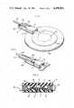
- FIG. 1is a perspective view of a connector of this invention shown electrically connected to the terminal portion of an electrode that comprises a printed circuit on a thin sheet of plastic material;
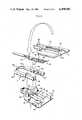
- FIG. 2is an exploded perspective view of the connector and showing the top section of the connector inverted (the large arrow showing inversion prior to assembly) for purposes of clarity of Illustration;
- FIG. 3is an enlarged top plan view of the connector partially broken away by removal of the top section and partially in section;
- FIG. 4is a sectional view taken approximately along line 4--4 of FIG. 3;
- FIG. 5is a fragmentary sectional view taken along line 5--5 of FIG. 4;
- FIG. 6is a perspective view of a modified form of the invention.
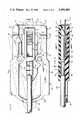
- FIG. 7is an enlarged plan view of the connector of FIG. 6 but embodying a strain relief member
- FIG. 8is a sectional view taken along line 8--8 of FIG. 7;
- FIG. 9is a top plan view of a further embodiment of the invention and which utilizes auxiliary springs for biasing the jaws closed.
- the housing 2comprises a top section 4 and an opposed bottom section 6 which cooperate to receive a jaw assembly 8 and an electrical terminal 10, all of which will presently be more fully described.
- the housing 2is formed with a cavity 12 having front opening 14 and a rear opening 16 each for providing communication from the cavity 12 to the exterior of the housing.
- the electrical terminal 10is within the cavity 12 and is presented toward the front opening 14 for receiving an electrical conductor in the form of a printed circuit lead 16 which in turn forms a printed circuit connection with electrode 18.
- Electrode 18 and the lead 16are imprinted on a thin sheet of plastic 20 which may be a resin of the type sold under the trademark Mylar.
- the sheet 20has a terminal strip 22 having a rounded forward end 24 (FIG. 3) adjacent to which are notches 27, 27 on opposite sides of the strip 22. Attached to the sheet 20 except at the lead 22 is a conventional foam elastomer pad 29.
- the bottom housing section 6includes a terminal well 26 forming part of the cavity 12.
- the terminal wellhas front and rear shoulders 28, 30 for receiving and retaining the terminal 10.
- the bottom 6furthermore includes pivot posts 32, 32; front end plateaus 34, 34; and ribs 36, 36 at the side boundaries of the terminal well 26.
- Also formed on the section 6is a rear wall 38 the forward vertical edge of which defines a shoulder 30.
- the sheet metal terminal 10includes a body portion 40 of generally rectangular configuration from which is struck a tongue 42 having angularly related sections 44, 46 the forward section 46 of which engages the shoulder 28 and the rearward section 44 of which terminates in a flange that engages the shoulder 30.
- the body portion 40has a forwardly extending lip 48 which diverges with respect to the tongue section 46 for receiving electrode terminal strip 22.
- the terminal 10also has a tail 50 having a multiplicity of sections for crimping to a wire 52 with an insulation 54. The tail 50 rests on the wall 38 and with the insulated wire projecting outwardly from the rear opening 16.
- the jaw assembly 8comprises a one-piece plastic member having opposed jaws 56, 56 with gripper ends 58, 58 at one end thereof and with the arms of the jaws projecting outwardly from the housing and terminating in an arcuate resilient member 60.
- the jawshave holes 62, 62 for pivotal connection respectively with the pivot posts 32, 32 whereby the spring member 60 biases the jaws to the full line position shown in FIG. 3, namely to the jaw-closed or conductor retaining positions in which the gripper ends 58, 58 are in the notches 27, 27.
- the jaw armsmay, however, be depressed in opposition to the force of the spring member 60 to move the gripper ends 58, 58 to the broken line position shown in FIG. 3 to permit insertion of the terminal strip 22 into or withdrawal of the terminal strip 22 from the connector.
- the spring member 60has a notch 64 to provide clearance for the wire insulation 54.
- the top section 4comprises weldment lugs 66, 66 and a generally U-shaped wall or rib 68, the portion 69 of which provides a flange at the front opening 14 and an abutment for the terminal lip 48.
- the body of the section 4also has shallow holes 70, 70 that receive the tops of the posts 32, 32.
- the sections 4, 6are ultrasonically welded together along their interfaces at the plateaus 34, 34 and the weldment lugs 66, 66.
- FIG. 6The form of the invention shown in FIG. 6 is similar to that shown in FIGS. 1-5 and the like reference numerals in FIG. 6 as compared to FIGS. 1-5 indicate like parts.
- the jaw assembly 8acomprises jaws 56, 56 projecting from the housing but with the plastic resilient member 60 of FIGS. 1-5 being replaced by a U-shaped wire spring 72 that is embedded at its opposite ends respectively in the jaws 56a, 56a. This spring 72 biases the jaws to the jaw-closed position.
- FIGS. 7-9The forms of the invention shown in FIGS. 7-9 are similar to the forms previously described and like reference numerals in FIGS. 1-6 as compared to FIGS. 7-9 indicate like parts.
- a strain relief member 80is utilized to resist separation of the lead wire 54 from the terminal 10.
- the strain relief member 80serves to transmit forces from the lead wire 54 to the pivot posts 32 which are integral with the housing 2.
- the strain relief member 80includes a rear section 82 which is tapered and is formed with notches 83 to enhance its flexibility. As best seen in FIGS. 7 and 8 the lead wire 54 is embedded in the strain relief member.
- the strain relief member 80also includes a forward section 84 which abuts the housing 2.
- the bight portion of the U-shaped spring wire 72is molded in the generally sector-shaped center portion of the strain relief member 80 so that forces on the strain relief member 80 will be transmitted through the wire spring 72 to the jaws 56 and to the pivot posts 32, 32.
- the strain relief functionis therefore present regardless of whether or not the jaws are open (broken line position in FIG. 7) or are closed. Moreover the strain relief member 80 does not impair the flexing of the arms of the U-shaped spring 72.
- the strain relief arrangementis similar to that of FIGS. 7 and 8.
- relatively short flat springs 86, 86are embedded in the respective jaws 56, 56 and abut the forward section 84 of the strain relief member 80. These springs 86, 86 work in conjunction with and thereby aid the wire spring 72 to bias the jaws closed.
Landscapes
- Details Of Connecting Devices For Male And Female Coupling (AREA)
- Coupling Device And Connection With Printed Circuit (AREA)
- Multi-Conductor Connections (AREA)
- Cable Accessories (AREA)
- Connector Housings Or Holding Contact Members (AREA)
Abstract
Description
This invention relates to electrical connectors, and more particularly to improvements in connectors for making electrically conductive contact with a printed electric circuit conductor on a thin flexible sheet of dielectric material.
The connector of the present invention is primarily intended for use with a skin contact electrode for measuring some physiologic function, such as electrocardiography or electroencephalography, or the like. These skin contact electrodes generally require individual connections between each of the electrodes and the equipment that measures physiologic function. Accordingly, it is desirable that the electrical connector for the electrode be of a rapid or "quick connect" type so as to reduce the time required to connect up all of the electrodes used for the monitoring or measuring function. Furthermore, it sometimes happens that a patient may be disconnected from the monitoring function for purposes of other medical procedures but with the electrode remaining with the patient. Therefore, the electrodes and the connectors should be capable of ready connection when the measuring or monitoring function is to be resumed. Additionally, the connector should be of the "low profile" type in that the connector should be relatively flat. This is of importance in situations where an electrode is on the back of the patient because under such conditions the patient must lie on the electrode frequently both during surgery and after recovery. Comfort thus becomes a significant factor which should be considered by the medical personnel.
An object of this invention is to provide an electrical connector which can be readily connected to or removed from the terminal portion of an electrode wherein such terminal portion is an electrical conductor printed upon a sheet of relatively thin dielectric material.
A further object of this invention is to provide a low-profile type of connector which readily grips the printed circuit conductor constituting the lead to the electrode.
Still another object of this invention is to provide a connector of the type stated which embodies a novel strain relief construction for preventing separation of the connector lead wire from the terminal within the connector.
In accordance with the foregoing objects the connector comprises an electrically insulated housing having a cavity and an opening providing communication from the cavity to the exterior of the housing, an electrical terminal within said housing and being presented towards said opening for receiving and contacting an electrical conductor projecting through said opening, and means for releasably retaining said conductor in said housing and in contacting relationship with said terminal; said means comprising at least one jaw member pivotally mounted on said housing and movable from a conductor-retaining position to a conductor-release position at which the conductor can be inserted into or withdrawn from the housing through said opening to make or break contact with said terminal, and resilient means biasing said jaw to said conductor-retaining position.
In the form of the invention disclosed there is a pair of jaws pivotally mounted on opposite sides respectively of the terminal, said jaws being joined by the resilient means such that the jaws and the resilient means constitutes a structure having both jaws biased toward their conductor-retaining positions. The resilient means may be plastic integrallymolded with the jaws or the resilient means may be a metal spring wire that joins the jaws. The spring wire may be molded within a strain relief member that forms part of the aforesaid novel strain relief construction.
FIG. 1 is a perspective view of a connector of this invention shown electrically connected to the terminal portion of an electrode that comprises a printed circuit on a thin sheet of plastic material;
FIG. 2 is an exploded perspective view of the connector and showing the top section of the connector inverted (the large arrow showing inversion prior to assembly) for purposes of clarity of Illustration;
FIG. 3 is an enlarged top plan view of the connector partially broken away by removal of the top section and partially in section;
FIG. 4 is a sectional view taken approximately alongline 4--4 of FIG. 3;
FIG. 5 is a fragmentary sectional view taken along line 5--5 of FIG. 4;
FIG. 6 is a perspective view of a modified form of the invention;
FIG. 7 is an enlarged plan view of the connector of FIG. 6 but embodying a strain relief member;
FIG. 8 is a sectional view taken alongline 8--8 of FIG. 7; and
FIG. 9 is a top plan view of a further embodiment of the invention and which utilizes auxiliary springs for biasing the jaws closed.
Referring now in more detail to the drawing, which illustrates a preferred embodiment of the invention, there is shown ahousing 2 of a suitable plastic, for example, polycarbonate. Thehousing 2 comprises atop section 4 and anopposed bottom section 6 which cooperate to receive ajaw assembly 8 and anelectrical terminal 10, all of which will presently be more fully described. Thehousing 2 is formed with acavity 12 having front opening 14 and arear opening 16 each for providing communication from thecavity 12 to the exterior of the housing. Theelectrical terminal 10 is within thecavity 12 and is presented toward thefront opening 14 for receiving an electrical conductor in the form of a printedcircuit lead 16 which in turn forms a printed circuit connection with electrode 18. Electrode 18 and thelead 16 are imprinted on a thin sheet ofplastic 20 which may be a resin of the type sold under the trademark Mylar. Thesheet 20 has aterminal strip 22 having a rounded forward end 24 (FIG. 3) adjacent to which arenotches strip 22. Attached to thesheet 20 except at thelead 22 is a conventionalfoam elastomer pad 29.
Thebottom housing section 6 includes aterminal well 26 forming part of thecavity 12. The terminal well has front andrear shoulders terminal 10. Thebottom 6 furthermore includespivot posts front end plateaus ribs section 6 is arear wall 38 the forward vertical edge of which defines ashoulder 30.
Thesheet metal terminal 10 includes abody portion 40 of generally rectangular configuration from which is struck atongue 42 having angularlyrelated sections forward section 46 of which engages theshoulder 28 and therearward section 44 of which terminates in a flange that engages theshoulder 30. Thebody portion 40 has a forwardly extendinglip 48 which diverges with respect to thetongue section 46 for receivingelectrode terminal strip 22. Theterminal 10 also has atail 50 having a multiplicity of sections for crimping to awire 52 with aninsulation 54. Thetail 50 rests on thewall 38 and with the insulated wire projecting outwardly from therear opening 16.
Thejaw assembly 8 comprises a one-piece plastic member having opposedjaws gripper ends resilient member 60. The jaws haveholes pivot posts spring member 60 biases the jaws to the full line position shown in FIG. 3, namely to the jaw-closed or conductor retaining positions in which the gripper ends 58, 58 are in thenotches spring member 60 to move the gripper ends 58, 58 to the broken line position shown in FIG. 3 to permit insertion of theterminal strip 22 into or withdrawal of theterminal strip 22 from the connector. Thespring member 60 has anotch 64 to provide clearance for thewire insulation 54.
Thetop section 4 comprisesweldment lugs rib 68, theportion 69 of which provides a flange at the front opening 14 and an abutment for theterminal lip 48. The body of thesection 4 also hasshallow holes posts sections plateaus weldment lugs
Use of the connector will be apparent from the foregoing description. With the gripper ends 58, 58 spread apart theterminal strip 22 is inserted into theopening 14 as far as it will go whereupon the jaws are released so that thejaw grippers notches strip 22 from the connector. The printedcircuit lead 16 will be retained in conductive engagement with theterminal 10. Disconnecting the printedcircuit lead 16 is effective simply by opening the jaws and retracting theterminal strip portion 22.
The form of the invention shown in FIG. 6 is similar to that shown in FIGS. 1-5 and the like reference numerals in FIG. 6 as compared to FIGS. 1-5 indicate like parts. However, thejaw assembly 8a comprisesjaws resilient member 60 of FIGS. 1-5 being replaced by aU-shaped wire spring 72 that is embedded at its opposite ends respectively in thejaws spring 72 biases the jaws to the jaw-closed position.
The forms of the invention shown in FIGS. 7-9 are similar to the forms previously described and like reference numerals in FIGS. 1-6 as compared to FIGS. 7-9 indicate like parts. However, in FIGS. 7-9 astrain relief member 80 is utilized to resist separation of thelead wire 54 from theterminal 10. Thestrain relief member 80 serves to transmit forces from thelead wire 54 to thepivot posts 32 which are integral with thehousing 2. Thestrain relief member 80 includes arear section 82 which is tapered and is formed withnotches 83 to enhance its flexibility. As best seen in FIGS. 7 and 8 thelead wire 54 is embedded in the strain relief member. Thestrain relief member 80 also includes aforward section 84 which abuts thehousing 2. The bight portion of the U-shapedspring wire 72 is molded in the generally sector-shaped center portion of thestrain relief member 80 so that forces on thestrain relief member 80 will be transmitted through thewire spring 72 to thejaws 56 and to thepivot posts strain relief member 80 does not impair the flexing of the arms of theU-shaped spring 72.
In the form of the invention shown in FIG. 9 the strain relief arrangement is similar to that of FIGS. 7 and 8. However, in the connector of FIG. 9 relatively shortflat springs respective jaws forward section 84 of thestrain relief member 80. Thesesprings wire spring 72 to bias the jaws closed.
Claims (9)
1. An electrical connector comprising an electrically insulated housing having a cavity and an opening providing communication from the cavity to the exterior of the housing, an electrical terminal within said cavity and having a first end presented toward said opening for receiving and contacting an electrical conductor projecting through said opening, a lead wire electrically connected to the second end of said terminal and extending from said housing, and means for releasably retaining said conductor in said housing and in contacting relationship with said terminal; said means comprising at least one jaw member pivotally mounted on said housing and movable from a conductor-retaining position to a conductor-release position at which the conductor can be inserted into or withdrawn from the housing through said opening to make or break contact with said terminal, and resilient means biasing said jaw member to said conductor-retaining position, said resilient means comprising a U-shaped length of wire one end of which is affixed to said jaw member, and a strain relief member molded over said lead wire with a segment of the return bend portion of the U-shaped wire embedded in said strain relief member for transmittal of strain from the lead wire to said U-shaped wire providing said resilient means.
2. A connector according to claim 1 having a pair of jaws members pivotally mounted on opposite sides respectively of said terminal, said jaw members being joined by said resilient means such that the jaw members and resilient means constitute a structure with both jaw members being biased toward their conductor-retaining positions, said jaw members being of an electrically insulating material.
3. A connector according to claim 2 in which said terminal has sections diverging toward said opening and shaped to receive a sheet of material having said conductor printed thereon, said sheet having notches for receiving the jaw members.
4. A connector according to claim 1 including auxiliary spring means disposed between said jaw member and said strain relief member and operable in aid of said resilient means.
5. An electrical connector comprising an electrically insulated housing having a cavity and an opening providing communication from the cavity to the exterior of the housing, an electrical terminal within said cavity and having a first end presented toward said opening for receiving and contacting an electrical conductor projecting through said opening, and means for releasably retaining said conductor in said housing and in contacting relationship with said terminal; said means comprising a pair of jaw members pivotally mounted on opposite sides of said housing and movable from a conductor-retaining position to a conductor-release position at which the conductor can be inserted into or withdrawn from the housing through said opening to make or break contact with said terminal, each said jaw member being pivotally mounted intermediate the respective ends thereof to define a gripper portion and an arm portion, said arm portion of each jaw member being depressible to move the jaw member from the conductor-retaining position to the conductor-release position, and resilient means biasing said jaw members to said conductor-retaining position, said resilient means being joined to the arm portion of each jaw member, such that the resilient means and the jaw member define an integral structure, with said resilient means biasing said arm portions outwardly of the housing and correspondingly urging said gripper portions inwardly of the housing to the conductor retaining position, and wherein said resilient means is in the form of a U-shaped link of spring wire having the ends thereof embedded in the gripper portions of the respective jaw members.
6. An electrical connector according to claim 5 wherein said electrical terminal has sections diverging toward said opening and shaped to receive a sheet of dielectric material having said conductor printed thereon, said sheet having notches for receiving the ends of the gripper portion of the jaw members.
7. An electrical connector comprising an electrically insulated housing having a cavity and an opening providing communication from the cavity to the exterior of the housing, an electrical terminal within said cavity and having a first end presented toward said opening for receiving and contacting an electrical conductor projecting through said opening, and means for releasably retaining said conductor in said housing and in contacting relationship with said terminal; said means comprising a pair of jaw members pivotally mounted on opposite sides of said housing and movable from a conductor-retaining position to a conductor-release position at which the conductor can be inserted into or withdrawn from the housing through said opening to make or break contact with said terminal, each said jaw member being pivotally mounted intermediate the respective ends thereof to define a gripper portion and an arm portion, said arm portion of each jaw member being depressible to move the jaw member from the conductor-retaining position to the conductor-release position, and resilient means biasing said jaw members to said conductor-retaining position, said resilient means being joined to the arm portion of each jaw member, such that the resilient means and the jaw member define an integral structure, with said resilient means biasing said arm portions outwardly of the housing and correspondingly urging said gripper portions inwardly of the housing to the conductor retaining position, and further including a lead wire connected to said electrical terminal, and a strain relief member abutting said housing for resisting separation of the lead wire from said electrical terminal, and said resilient means being embedded in said strain relief member.
8. An electrical connector according to claim 7 wherein said housing is of a two-piece construction, and defines a pair of opposed post members upon which said jaw members are pivotally mounted.
9. An electrical connector according to claim 7 including auxiliary spring means disposed in association with each said jaw member and operable in aid of said resilient means.
Priority Applications (12)
| Application Number | Priority Date | Filing Date | Title |
|---|---|---|---|
| US06/338,358US4490003A (en) | 1982-01-11 | 1982-01-11 | Electrical connector |
| CA000417680ACA1191219A (en) | 1982-01-11 | 1982-12-14 | Electrical connector |
| AU91530/82AAU9153082A (en) | 1982-01-11 | 1982-12-15 | Electrical connector |
| NL8205035ANL8205035A (en) | 1982-01-11 | 1982-12-29 | ELECTRICAL CONNECTOR. |
| SE8300031ASE8300031L (en) | 1982-01-11 | 1983-01-04 | ELECTRICAL CONNECTOR |
| GB08300148AGB2113482B (en) | 1982-01-11 | 1983-01-05 | Electrical connectors |
| JP58000288AJPS58121579A (en) | 1982-01-11 | 1983-01-06 | Electric connector |
| IT47520/83AIT1197540B (en) | 1982-01-11 | 1983-01-07 | IMPROVEMENT IN ELECTRIC CONNECTORS |
| DE19833300348DE3300348A1 (en) | 1982-01-11 | 1983-01-07 | ELECTRICAL PLUG |
| ES518871AES8402678A1 (en) | 1982-01-11 | 1983-01-10 | Electrical connector |
| FR8300280AFR2519810A1 (en) | 1982-01-11 | 1983-01-10 | ELECTRICAL CONNECTOR, NOTAMMANT FOR ELECTRODE TO PLACE IN CONTACT WITH THE SKIN OF A PATIENT |
| BR8300080ABR8300080A (en) | 1982-01-11 | 1983-01-10 | ELECTRICAL CONNECTOR |
Applications Claiming Priority (1)
| Application Number | Priority Date | Filing Date | Title |
|---|---|---|---|
| US06/338,358US4490003A (en) | 1982-01-11 | 1982-01-11 | Electrical connector |
Publications (1)
| Publication Number | Publication Date |
|---|---|
| US4490003Atrue US4490003A (en) | 1984-12-25 |
Family
ID=23324505
Family Applications (1)
| Application Number | Title | Priority Date | Filing Date |
|---|---|---|---|
| US06/338,358Expired - Fee RelatedUS4490003A (en) | 1982-01-11 | 1982-01-11 | Electrical connector |
Country Status (12)
| Country | Link |
|---|---|
| US (1) | US4490003A (en) |
| JP (1) | JPS58121579A (en) |
| AU (1) | AU9153082A (en) |
| BR (1) | BR8300080A (en) |
| CA (1) | CA1191219A (en) |
| DE (1) | DE3300348A1 (en) |
| ES (1) | ES8402678A1 (en) |
| FR (1) | FR2519810A1 (en) |
| GB (1) | GB2113482B (en) |
| IT (1) | IT1197540B (en) |
| NL (1) | NL8205035A (en) |
| SE (1) | SE8300031L (en) |
Cited By (43)
| Publication number | Priority date | Publication date | Assignee | Title |
|---|---|---|---|---|
| USD328283S (en) | 1990-04-02 | 1992-07-28 | Minnesota Mining And Manufacturing Company | Electrical clip for the lead wire of a medical electrode |
| US5397310A (en)* | 1991-10-11 | 1995-03-14 | Boston Scientific Corporation | Catheter introducer sheath assembly |
| USD359862S (en) | 1994-03-18 | 1995-07-04 | Rousch Paula M | Traveler's tray |
| US5489274A (en)* | 1992-10-09 | 1996-02-06 | Boston Scientific Corporation | Rotatable medical valve closure |
| US5562485A (en)* | 1994-09-06 | 1996-10-08 | White Consolidated Industries, Inc. | Wiring connection |
| US5934925A (en)* | 1995-10-16 | 1999-08-10 | Masimo Corporation | Patient cable connector |
| US6152754A (en)* | 1999-12-21 | 2000-11-28 | Masimo Corporation | Circuit board based cable connector |
| US6541756B2 (en) | 1991-03-21 | 2003-04-01 | Masimo Corporation | Shielded optical probe having an electrical connector |
| US20030228806A1 (en)* | 2002-06-11 | 2003-12-11 | Harada Industry Co., Ltd. | Connection terminal unit for antenna and manufacturing method of connection terminal unit for antenna |
| US20050196995A1 (en)* | 2004-03-04 | 2005-09-08 | Tsung-Kan Cheng | Quick release connector for connecting terminal board |
| US20050261636A1 (en)* | 2004-03-18 | 2005-11-24 | Rome Guy T | Valved catheter |
| US20060015086A1 (en)* | 2004-04-01 | 2006-01-19 | Kelly Rasmussen | Catheter connector system |
| US7035689B1 (en)* | 2002-10-14 | 2006-04-25 | Pacesetter, Inc. | Connector and retention mechanism for an implantable medical device |
| US20080009832A1 (en)* | 2005-06-20 | 2008-01-10 | C. R. Bard, Inc. | Connection system for multi-lumen catheter |
| US20090043270A1 (en)* | 2007-08-10 | 2009-02-12 | C.R. Bard, Inc. | Effusion drainage kits and methods for packaging the same |
| US20090280688A1 (en)* | 2006-06-28 | 2009-11-12 | Kouhei Kawada | Circuit Board Built-In Connector and Catcher |
| US20100007566A1 (en)* | 2008-07-08 | 2010-01-14 | Harada Industry Co., Ltd. | Vehicle Roof Mount Antenna |
| US20100331823A1 (en)* | 2009-06-26 | 2010-12-30 | C. R. Bard, Inc. | Proximally trimmable catheter including pre-attached bifurcation and related methods |
| US20110009849A1 (en)* | 2005-09-26 | 2011-01-13 | C.R. Bard, Inc. | Catheter connection systems |
| US7883502B2 (en) | 2004-03-18 | 2011-02-08 | C. R. Bard, Inc. | Connector system for a proximally trimmable catheter |
| US20110102269A1 (en)* | 2009-11-02 | 2011-05-05 | Masato Sato | Patch antenna |
| US8083728B2 (en) | 2004-03-18 | 2011-12-27 | C. R. Bard, Inc. | Multifunction adaptor for an open-ended catheter |
| US8177771B2 (en) | 2004-03-18 | 2012-05-15 | C. R. Bard, Inc. | Catheter connector |
| US8337475B2 (en) | 2004-10-12 | 2012-12-25 | C. R. Bard, Inc. | Corporeal drainage system |
| US8636721B2 (en) | 2003-11-20 | 2014-01-28 | Henry M. Jackson Foundation For The Advancement Of Military Medicine, Inc. | Portable hand pump for evacuation of fluids |
| US8692725B2 (en) | 2007-12-20 | 2014-04-08 | Harada Industry Co., Ltd. | Patch antenna device |
| US8816917B2 (en) | 2011-01-12 | 2014-08-26 | Harada Industry Co., Ltd. | Antenna device |
| CN104412461A (en)* | 2012-06-26 | 2015-03-11 | 矢崎总业株式会社 | Connector |
| US8994475B2 (en) | 2008-05-27 | 2015-03-31 | Harada Industry Co., Ltd. | Vehicle-mounted noise filter |
| USD726696S1 (en) | 2012-09-12 | 2015-04-14 | Harada Industry Co., Ltd. | Vehicle antenna |
| US9153864B2 (en) | 2011-02-15 | 2015-10-06 | Harada Industry Co., Ltd. | Vehicle pole antenna |
| US9225055B2 (en) | 2011-03-24 | 2015-12-29 | Harada Industry Co., Ltd. | Antenna device |
| US9560998B2 (en) | 2006-10-12 | 2017-02-07 | Masimo Corporation | System and method for monitoring the life of a physiological sensor |
| US9795739B2 (en) | 2009-05-20 | 2017-10-24 | Masimo Corporation | Hemoglobin display and patient treatment |
| US11191485B2 (en) | 2006-06-05 | 2021-12-07 | Masimo Corporation | Parameter upgrade system |
| US11304772B2 (en) | 2018-05-18 | 2022-04-19 | Bard Access Systems, Inc. | Connection systems and methods thereof for establishing an electrical connection through a drape |
| US11344318B2 (en) | 2016-07-18 | 2022-05-31 | Merit Medical Systems, Inc. | Inflatable radial artery compression device |
| US11471647B2 (en) | 2014-11-07 | 2022-10-18 | C. R. Bard, Inc. | Connection system for tunneled catheters |
| US11737848B2 (en) | 2019-07-29 | 2023-08-29 | Bard Access Systems, Inc. | Connection systems and methods for establishing optical and electrical connections through a drape |
| US11896782B2 (en) | 2017-08-23 | 2024-02-13 | C. R. Bard, Inc. | Priming and tunneling system for a retrograde catheter assembly |
| US11936132B2 (en) | 2018-01-29 | 2024-03-19 | Bard Access Systems, Inc. | Connection system for establishing an electrical connection through a drape and methods thereof |
| US12029498B2 (en) | 2019-08-08 | 2024-07-09 | Bard Access Systems, Inc. | Optical-fiber connector modules including shape-sensing systems and methods thereof |
| US12426864B2 (en) | 2021-06-18 | 2025-09-30 | Merit Medical Systems, Inc. | Hemostasis devices and methods of use |
Families Citing this family (8)
| Publication number | Priority date | Publication date | Assignee | Title |
|---|---|---|---|---|
| SE8502048D0 (en)* | 1985-04-26 | 1985-04-26 | Astra Tech Ab | VACUUM FIXED HALLS FOR MEDICAL USE |
| JPH0232241Y2 (en)* | 1985-10-02 | 1990-09-03 | ||
| GB8614118D0 (en)* | 1986-06-10 | 1986-07-16 | Allied Corp | Rectangular connection |
| FR2660020B1 (en)* | 1990-03-26 | 1994-07-22 | Peugeot | IGNITION DEVICE FOR INTERNAL COMBUSTION ENGINE. |
| FR2663472B1 (en)* | 1990-06-14 | 1994-08-26 | Labinal | DEVICE FOR LOCKING TWO HOUSING ELEMENTS OF AN ELECTRICAL CONNECTOR. |
| US5314347A (en)* | 1992-08-13 | 1994-05-24 | Molex Incorporated | Latchable electrical connector system |
| DE19820901A1 (en)* | 1998-05-09 | 1999-11-11 | Zahnradfabrik Friedrichshafen | Electrical connector, e.g. for magnetic valve or pressure regulator |
| JP6701244B2 (en)* | 2017-06-28 | 2020-05-27 | タツタ電線株式会社 | Connectors, wires with connectors, and sensors for medical devices |
Citations (9)
| Publication number | Priority date | Publication date | Assignee | Title |
|---|---|---|---|---|
| US3093432A (en)* | 1960-10-27 | 1963-06-11 | Honeywell Regulator Co | Molded electrical cord connector |
| US3140907A (en)* | 1960-06-03 | 1964-07-14 | Int Standard Electric Corp | Electrical spring contact sockets |
| DE1200409B (en)* | 1960-06-09 | 1965-09-09 | Dr Oskar Vierling | Device for locking and unlocking circuit boards |
| US3278714A (en)* | 1963-11-14 | 1966-10-11 | Int Standard Electric Corp | Supporting frame for printed circuit board |
| US3737833A (en)* | 1971-05-12 | 1973-06-05 | Honeywell Inf Systems | Ribbon cable connector system having feed thru connector |
| CA968866A (en)* | 1972-03-27 | 1975-06-03 | Roy G. Szanny | Detachable fastening clip |
| US4008942A (en)* | 1975-07-29 | 1977-02-22 | General Signal Corporation | Printed circuit board holding spring |
| DE2801427A1 (en)* | 1977-01-14 | 1978-07-20 | Bunker Ramo | Safety locking device for two connectors plugged together - has two fingers with hooked ends, which are hinged on one part of connector assembly |
| US4243034A (en)* | 1978-10-17 | 1981-01-06 | Viggo Ab | Cannula or catheter assembly |
Family Cites Families (3)
| Publication number | Priority date | Publication date | Assignee | Title |
|---|---|---|---|---|
| CH516233A (en)* | 1968-03-09 | 1971-11-30 | Hengstler Kg | Locking device for components that can be plugged into one another |
| DE2215221C3 (en)* | 1972-03-29 | 1975-06-19 | Swf-Spezialfabrik Fuer Autozubehoer Gustav Rau Gmbh, 7120 Bietigheim | Cable connector |
| US3970353A (en)* | 1974-08-29 | 1976-07-20 | Amp Incorporated | Locking clip |
- 1982
- 1982-01-11USUS06/338,358patent/US4490003A/ennot_activeExpired - Fee Related
- 1982-12-14CACA000417680Apatent/CA1191219A/ennot_activeExpired
- 1982-12-15AUAU91530/82Apatent/AU9153082A/ennot_activeAbandoned
- 1982-12-29NLNL8205035Apatent/NL8205035A/ennot_activeApplication Discontinuation
- 1983
- 1983-01-04SESE8300031Apatent/SE8300031L/ennot_activeApplication Discontinuation
- 1983-01-05GBGB08300148Apatent/GB2113482B/ennot_activeExpired
- 1983-01-06JPJP58000288Apatent/JPS58121579A/enactivePending
- 1983-01-07DEDE19833300348patent/DE3300348A1/ennot_activeWithdrawn
- 1983-01-07ITIT47520/83Apatent/IT1197540B/enactive
- 1983-01-10FRFR8300280Apatent/FR2519810A1/ennot_activeWithdrawn
- 1983-01-10BRBR8300080Apatent/BR8300080A/enunknown
- 1983-01-10ESES518871Apatent/ES8402678A1/ennot_activeExpired
Patent Citations (9)
| Publication number | Priority date | Publication date | Assignee | Title |
|---|---|---|---|---|
| US3140907A (en)* | 1960-06-03 | 1964-07-14 | Int Standard Electric Corp | Electrical spring contact sockets |
| DE1200409B (en)* | 1960-06-09 | 1965-09-09 | Dr Oskar Vierling | Device for locking and unlocking circuit boards |
| US3093432A (en)* | 1960-10-27 | 1963-06-11 | Honeywell Regulator Co | Molded electrical cord connector |
| US3278714A (en)* | 1963-11-14 | 1966-10-11 | Int Standard Electric Corp | Supporting frame for printed circuit board |
| US3737833A (en)* | 1971-05-12 | 1973-06-05 | Honeywell Inf Systems | Ribbon cable connector system having feed thru connector |
| CA968866A (en)* | 1972-03-27 | 1975-06-03 | Roy G. Szanny | Detachable fastening clip |
| US4008942A (en)* | 1975-07-29 | 1977-02-22 | General Signal Corporation | Printed circuit board holding spring |
| DE2801427A1 (en)* | 1977-01-14 | 1978-07-20 | Bunker Ramo | Safety locking device for two connectors plugged together - has two fingers with hooked ends, which are hinged on one part of connector assembly |
| US4243034A (en)* | 1978-10-17 | 1981-01-06 | Viggo Ab | Cannula or catheter assembly |
Cited By (90)
| Publication number | Priority date | Publication date | Assignee | Title |
|---|---|---|---|---|
| USD328283S (en) | 1990-04-02 | 1992-07-28 | Minnesota Mining And Manufacturing Company | Electrical clip for the lead wire of a medical electrode |
| US7132641B2 (en) | 1991-03-21 | 2006-11-07 | Masimo Corporation | Shielded optical probe having an electrical connector |
| US6541756B2 (en) | 1991-03-21 | 2003-04-01 | Masimo Corporation | Shielded optical probe having an electrical connector |
| US5989223A (en)* | 1991-10-11 | 1999-11-23 | Boston Scientific Corporation | Rotatable medical valve closure |
| US5397310A (en)* | 1991-10-11 | 1995-03-14 | Boston Scientific Corporation | Catheter introducer sheath assembly |
| US5489274A (en)* | 1992-10-09 | 1996-02-06 | Boston Scientific Corporation | Rotatable medical valve closure |
| USD359862S (en) | 1994-03-18 | 1995-07-04 | Rousch Paula M | Traveler's tray |
| US5562485A (en)* | 1994-09-06 | 1996-10-08 | White Consolidated Industries, Inc. | Wiring connection |
| US5934925A (en)* | 1995-10-16 | 1999-08-10 | Masimo Corporation | Patient cable connector |
| US6280213B1 (en) | 1995-10-16 | 2001-08-28 | Masimo Corporation | Patient cable connector |
| US6152754A (en)* | 1999-12-21 | 2000-11-28 | Masimo Corporation | Circuit board based cable connector |
| WO2001047066A3 (en)* | 1999-12-21 | 2002-01-10 | Masimo Corp | Circuit board based cable connector |
| US20030228806A1 (en)* | 2002-06-11 | 2003-12-11 | Harada Industry Co., Ltd. | Connection terminal unit for antenna and manufacturing method of connection terminal unit for antenna |
| US7037144B2 (en)* | 2002-06-11 | 2006-05-02 | Harada Industry Co., Ltd. | Connection terminal unit for antenna and manufacturing method of connection terminal unit for antenna |
| US7035689B1 (en)* | 2002-10-14 | 2006-04-25 | Pacesetter, Inc. | Connector and retention mechanism for an implantable medical device |
| US10213532B2 (en) | 2003-11-20 | 2019-02-26 | The Henry M. Jackson Foundation For The Advancement Of Military Medicine, Inc. | Portable hand pump for evacuation of fluids |
| US8636721B2 (en) | 2003-11-20 | 2014-01-28 | Henry M. Jackson Foundation For The Advancement Of Military Medicine, Inc. | Portable hand pump for evacuation of fluids |
| US9907887B2 (en) | 2003-11-20 | 2018-03-06 | The Henry M. Jackson Foundation For The Advancement Of Military Medicine, Inc. | Portable hand pump for evacuation of fluids |
| US9393353B2 (en) | 2003-11-20 | 2016-07-19 | The Henry M. Jackson Foundation For The Advancement Of Military Medicine, Inc. | Portable hand pump for evacuation of fluids |
| US6942514B1 (en)* | 2004-03-04 | 2005-09-13 | C-One Technology Corporation | Quick release connector for connecting terminal board |
| US20050196995A1 (en)* | 2004-03-04 | 2005-09-08 | Tsung-Kan Cheng | Quick release connector for connecting terminal board |
| US8177771B2 (en) | 2004-03-18 | 2012-05-15 | C. R. Bard, Inc. | Catheter connector |
| US8083728B2 (en) | 2004-03-18 | 2011-12-27 | C. R. Bard, Inc. | Multifunction adaptor for an open-ended catheter |
| US8523840B2 (en) | 2004-03-18 | 2013-09-03 | C. R. Bard, Inc. | Connector system for a proximally trimmable catheter |
| US7854731B2 (en) | 2004-03-18 | 2010-12-21 | C. R. Bard, Inc. | Valved catheter |
| US20050261636A1 (en)* | 2004-03-18 | 2005-11-24 | Rome Guy T | Valved catheter |
| US7883502B2 (en) | 2004-03-18 | 2011-02-08 | C. R. Bard, Inc. | Connector system for a proximally trimmable catheter |
| US20110098653A1 (en)* | 2004-03-18 | 2011-04-28 | C. R. Bard, Inc. | Connector system for a proximally trimmable catheter |
| US20080200901A1 (en)* | 2004-04-01 | 2008-08-21 | C. R. Bard, Inc. | Catheter connector system |
| US7377915B2 (en) | 2004-04-01 | 2008-05-27 | C. R. Bard, Inc. | Catheter connector system |
| US20060015086A1 (en)* | 2004-04-01 | 2006-01-19 | Kelly Rasmussen | Catheter connector system |
| US8177770B2 (en) | 2004-04-01 | 2012-05-15 | C. R. Bard, Inc. | Catheter connector system |
| US9913935B2 (en) | 2004-10-12 | 2018-03-13 | C. R. Bard, Inc. | Corporeal drainage system |
| US9295764B2 (en) | 2004-10-12 | 2016-03-29 | C. R. Bard, Inc. | Corporeal drainage system |
| US10946123B2 (en) | 2004-10-12 | 2021-03-16 | Merit Medical Systems, Inc. | Corporeal drainage system |
| US8337475B2 (en) | 2004-10-12 | 2012-12-25 | C. R. Bard, Inc. | Corporeal drainage system |
| US8617138B2 (en) | 2005-06-20 | 2013-12-31 | C. R. Bard, Inc. | Connection system for multi-lumen catheter |
| US20110098679A1 (en)* | 2005-06-20 | 2011-04-28 | C. R. Bard, Inc. | Connection system for multi-lumen catheter |
| US7875019B2 (en) | 2005-06-20 | 2011-01-25 | C. R. Bard, Inc. | Connection system for multi-lumen catheter |
| US20080009832A1 (en)* | 2005-06-20 | 2008-01-10 | C. R. Bard, Inc. | Connection system for multi-lumen catheter |
| US8206376B2 (en) | 2005-06-20 | 2012-06-26 | C. R. Bard, Inc. | Connection system for multi-lumen catheter |
| US8852168B2 (en) | 2005-06-20 | 2014-10-07 | C. R. Bard, Inc. | Connection system for multi-lumen catheter |
| US8235971B2 (en) | 2005-09-26 | 2012-08-07 | C. R. Bard, Inc. | Catheter connection systems |
| US20110009849A1 (en)* | 2005-09-26 | 2011-01-13 | C.R. Bard, Inc. | Catheter connection systems |
| US8177772B2 (en) | 2005-09-26 | 2012-05-15 | C. R. Bard, Inc. | Catheter connection systems |
| US11191485B2 (en) | 2006-06-05 | 2021-12-07 | Masimo Corporation | Parameter upgrade system |
| US12109048B2 (en) | 2006-06-05 | 2024-10-08 | Masimo Corporation | Parameter upgrade system |
| US20090280688A1 (en)* | 2006-06-28 | 2009-11-12 | Kouhei Kawada | Circuit Board Built-In Connector and Catcher |
| US7845983B2 (en)* | 2006-06-28 | 2010-12-07 | Harada Industry Co., Ltd. | Circuit board built-in connector and catcher |
| US10863938B2 (en) | 2006-10-12 | 2020-12-15 | Masimo Corporation | System and method for monitoring the life of a physiological sensor |
| US10039482B2 (en) | 2006-10-12 | 2018-08-07 | Masimo Corporation | System and method for monitoring the life of a physiological sensor |
| US12127835B2 (en) | 2006-10-12 | 2024-10-29 | Masimo Corporation | System and method for monitoring the life of a physiological sensor |
| US11857319B2 (en) | 2006-10-12 | 2024-01-02 | Masimo Corporation | System and method for monitoring the life of a physiological sensor |
| US11317837B2 (en) | 2006-10-12 | 2022-05-03 | Masimo Corporation | System and method for monitoring the life of a physiological sensor |
| US9560998B2 (en) | 2006-10-12 | 2017-02-07 | Masimo Corporation | System and method for monitoring the life of a physiological sensor |
| US10342470B2 (en) | 2006-10-12 | 2019-07-09 | Masimo Corporation | System and method for monitoring the life of a physiological sensor |
| US20090043270A1 (en)* | 2007-08-10 | 2009-02-12 | C.R. Bard, Inc. | Effusion drainage kits and methods for packaging the same |
| US8692725B2 (en) | 2007-12-20 | 2014-04-08 | Harada Industry Co., Ltd. | Patch antenna device |
| US8994475B2 (en) | 2008-05-27 | 2015-03-31 | Harada Industry Co., Ltd. | Vehicle-mounted noise filter |
| US20100007566A1 (en)* | 2008-07-08 | 2010-01-14 | Harada Industry Co., Ltd. | Vehicle Roof Mount Antenna |
| US8941544B2 (en) | 2008-07-08 | 2015-01-27 | Harada Industry Co., Ltd. | Vehicle roof mount antenna |
| US10953156B2 (en) | 2009-05-20 | 2021-03-23 | Masimo Corporation | Hemoglobin display and patient treatment |
| US12318580B2 (en) | 2009-05-20 | 2025-06-03 | Masimo Corporation | Hemoglobin display and patient treatment |
| US11752262B2 (en) | 2009-05-20 | 2023-09-12 | Masimo Corporation | Hemoglobin display and patient treatment |
| US10413666B2 (en) | 2009-05-20 | 2019-09-17 | Masimo Corporation | Hemoglobin display and patient treatment |
| US9795739B2 (en) | 2009-05-20 | 2017-10-24 | Masimo Corporation | Hemoglobin display and patient treatment |
| US8337484B2 (en) | 2009-06-26 | 2012-12-25 | C. R. Band, Inc. | Proximally trimmable catheter including pre-attached bifurcation and related methods |
| US20100331823A1 (en)* | 2009-06-26 | 2010-12-30 | C. R. Bard, Inc. | Proximally trimmable catheter including pre-attached bifurcation and related methods |
| US20110102269A1 (en)* | 2009-11-02 | 2011-05-05 | Masato Sato | Patch antenna |
| US8816917B2 (en) | 2011-01-12 | 2014-08-26 | Harada Industry Co., Ltd. | Antenna device |
| US9153864B2 (en) | 2011-02-15 | 2015-10-06 | Harada Industry Co., Ltd. | Vehicle pole antenna |
| US9287610B2 (en) | 2011-03-24 | 2016-03-15 | Harada Industry Co., Ltd. | Antenna device |
| US9225055B2 (en) | 2011-03-24 | 2015-12-29 | Harada Industry Co., Ltd. | Antenna device |
| US9680201B2 (en) | 2011-03-24 | 2017-06-13 | Harada Industry Co., Ltd. | Antenna device |
| US9825351B2 (en) | 2011-03-24 | 2017-11-21 | Harada Industry Co., Ltd. | Antenna device |
| CN104412461A (en)* | 2012-06-26 | 2015-03-11 | 矢崎总业株式会社 | Connector |
| US20150099396A1 (en)* | 2012-06-26 | 2015-04-09 | Yazaki Corporation | Connector |
| USD726696S1 (en) | 2012-09-12 | 2015-04-14 | Harada Industry Co., Ltd. | Vehicle antenna |
| US11471647B2 (en) | 2014-11-07 | 2022-10-18 | C. R. Bard, Inc. | Connection system for tunneled catheters |
| US11344318B2 (en) | 2016-07-18 | 2022-05-31 | Merit Medical Systems, Inc. | Inflatable radial artery compression device |
| US11896782B2 (en) | 2017-08-23 | 2024-02-13 | C. R. Bard, Inc. | Priming and tunneling system for a retrograde catheter assembly |
| US12237617B2 (en) | 2018-01-29 | 2025-02-25 | Bard Access Systems, Inc. | Connection system for establishing an electrical connection through a drape and methods thereof |
| US11936132B2 (en) | 2018-01-29 | 2024-03-19 | Bard Access Systems, Inc. | Connection system for establishing an electrical connection through a drape and methods thereof |
| US11628030B2 (en) | 2018-05-18 | 2023-04-18 | Bard Access Systems, Inc. | Connection systems and methods thereof for establishing an electrical connection through a drape |
| US12274526B2 (en) | 2018-05-18 | 2025-04-15 | Bard Access Systems, Inc. | Connection systems and methods thereof for establishing an electrical connection through a drape |
| US11304772B2 (en) | 2018-05-18 | 2022-04-19 | Bard Access Systems, Inc. | Connection systems and methods thereof for establishing an electrical connection through a drape |
| US12059228B2 (en) | 2019-07-29 | 2024-08-13 | Bard Access Systems, Inc. | Connection systems and methods for establishing optical and electrical connections through a drape |
| US11737848B2 (en) | 2019-07-29 | 2023-08-29 | Bard Access Systems, Inc. | Connection systems and methods for establishing optical and electrical connections through a drape |
| US12029498B2 (en) | 2019-08-08 | 2024-07-09 | Bard Access Systems, Inc. | Optical-fiber connector modules including shape-sensing systems and methods thereof |
| US12426864B2 (en) | 2021-06-18 | 2025-09-30 | Merit Medical Systems, Inc. | Hemostasis devices and methods of use |
Also Published As
| Publication number | Publication date |
|---|---|
| GB8300148D0 (en) | 1983-02-09 |
| SE8300031L (en) | 1983-07-12 |
| ES518871A0 (en) | 1984-02-01 |
| IT8347520A0 (en) | 1983-01-07 |
| GB2113482A (en) | 1983-08-03 |
| FR2519810A1 (en) | 1983-07-18 |
| DE3300348A1 (en) | 1983-07-21 |
| JPS58121579A (en) | 1983-07-19 |
| SE8300031D0 (en) | 1983-01-04 |
| AU9153082A (en) | 1983-07-21 |
| GB2113482B (en) | 1985-09-18 |
| IT1197540B (en) | 1988-12-06 |
| CA1191219A (en) | 1985-07-30 |
| BR8300080A (en) | 1983-09-20 |
| NL8205035A (en) | 1983-08-01 |
| ES8402678A1 (en) | 1984-02-01 |
Similar Documents
| Publication | Publication Date | Title |
|---|---|---|
| US4490003A (en) | Electrical connector | |
| US5232383A (en) | Medical snap connector | |
| US6363272B1 (en) | Connector for fetal probe | |
| EP0268364B1 (en) | Electrical connector | |
| US7255609B1 (en) | Biomedical electrode connector device | |
| KR100364377B1 (en) | Locking device for a connector | |
| US4401356A (en) | Electrical terminal | |
| US6487430B1 (en) | Electrode connector | |
| US4669798A (en) | Electrical terminal for flexible printed circuits | |
| US7753738B2 (en) | Electrical connector with an anti-dust device to avoid the poor contact from dust | |
| US4023879A (en) | Adjustable electrical connector with replaceable contact sub-assembly and variable strain relief | |
| US5295872A (en) | Biomedical electrical clasp | |
| AU581141B2 (en) | Electrical connector | |
| JPS61176082A (en) | Electric connector | |
| JPH0117239B2 (en) | ||
| JPS5324593A (en) | Improvement of electric contact and electric connector assembly | |
| US6062915A (en) | Nondeforming electrode connector | |
| EP0952629A3 (en) | Electrical connector for flat flexible circuitry | |
| US6554640B1 (en) | Radio communication equipment having a floating connector | |
| EP0788196A2 (en) | Plug socket | |
| US5116333A (en) | Bipolar handswitch adapter | |
| WO1997049143A1 (en) | Electrode connector | |
| US5137475A (en) | Medical electrical connector for flexible electrodes | |
| US6356778B1 (en) | Connector assembly for fetal scalp electrode | |
| CN112968330A (en) | Electric connector and electronic equipment |
Legal Events
| Date | Code | Title | Description |
|---|---|---|---|
| AS | Assignment | Owner name:C.R. BARD, INC., 731 CENTRAL AVE., MURRAY HILL A Free format text:ASSIGNMENT OF ASSIGNORS INTEREST.;ASSIGNOR:ROBINSON, EARL F.;REEL/FRAME:003974/0509 Effective date:19811229 | |
| FEPP | Fee payment procedure | Free format text:PAYOR NUMBER ASSIGNED (ORIGINAL EVENT CODE: ASPN); ENTITY STATUS OF PATENT OWNER: LARGE ENTITY | |
| REMI | Maintenance fee reminder mailed | ||
| REIN | Reinstatement after maintenance fee payment confirmed | ||
| FP | Lapsed due to failure to pay maintenance fee | Effective date:19881225 | |
| REMI | Maintenance fee reminder mailed | ||
| LAPS | Lapse for failure to pay maintenance fees | ||
| FP | Lapsed due to failure to pay maintenance fee | Effective date:19921227 | |
| STCH | Information on status: patent discontinuation | Free format text:PATENT EXPIRED DUE TO NONPAYMENT OF MAINTENANCE FEES UNDER 37 CFR 1.362 |