US4489616A - Digital fluid flow meter - Google Patents
Digital fluid flow meterDownload PDFInfo
- Publication number
- US4489616A US4489616AUS06/494,899US49489983AUS4489616AUS 4489616 AUS4489616 AUS 4489616AUS 49489983 AUS49489983 AUS 49489983AUS 4489616 AUS4489616 AUS 4489616A
- Authority
- US
- United States
- Prior art keywords
- impeller
- flow meter
- channel
- faces
- block
- Prior art date
- Legal status (The legal status is an assumption and is not a legal conclusion. Google has not performed a legal analysis and makes no representation as to the accuracy of the status listed.)
- Expired - Fee Related
Links
- 239000012530fluidSubstances0.000titleclaimsabstractdescription18
- 230000000994depressogenic effectEffects0.000claimsabstractdescription7
- 239000000126substanceSubstances0.000description4
- 238000010276constructionMethods0.000description2
- 239000000463materialSubstances0.000description2
- VNWKTOKETHGBQD-UHFFFAOYSA-NmethaneChemical compoundCVNWKTOKETHGBQD-UHFFFAOYSA-N0.000description2
- XLYOFNOQVPJJNP-UHFFFAOYSA-NwaterSubstancesOXLYOFNOQVPJJNP-UHFFFAOYSA-N0.000description2
- 239000007789gasSubstances0.000description1
- 239000002184metalSubstances0.000description1
- 238000012544monitoring processMethods0.000description1
- 239000003345natural gasSubstances0.000description1
Images

Classifications
- G—PHYSICS
- G01—MEASURING; TESTING
- G01F—MEASURING VOLUME, VOLUME FLOW, MASS FLOW OR LIQUID LEVEL; METERING BY VOLUME
- G01F1/00—Measuring the volume flow or mass flow of fluid or fluent solid material wherein the fluid passes through a meter in a continuous flow
- G01F1/05—Measuring the volume flow or mass flow of fluid or fluent solid material wherein the fluid passes through a meter in a continuous flow by using mechanical effects
- G01F1/06—Measuring the volume flow or mass flow of fluid or fluent solid material wherein the fluid passes through a meter in a continuous flow by using mechanical effects using rotating vanes with tangential admission
Definitions
- This inventionlies in the field of apparatus for measuring the flow rate and total flow of a selected fluid.
- fluid flow metersfrom the conventional home gas meter, that measures the flow of natural gas to the home, or the water meter that measures the total flow of water delivered to a home.
- flow metersfor specialized purposes, in connection with other devices such as chemical mixers and the like.
- One important application of this flow meterwould be with apparatus for monitoring the total flow of fluid through a purifier or other similar device, where a chemical action takes place and the chemical is consumed in the operation. It becomes important to know when the chemical is consumed and needs replacement and a simple small convenient and inexpensive flow meter such as that of this invention would be extremely useful.
- a slab of suitable materialwhich can be metal or plastic, and can be machined, cast or molded, for example. It comprises a body which conveniently can be a rectangular slab or a selected thickness T. A circular opening of selected radius R is drilled through the body from the first face to the second face, and an impeller is positioned inside that cylindrical cavity, with sufficient clearance that it can turn freely within the circumferential wall.
- a plurality of radial vanesare formed on the outer portions of the impeller equally spaced and similarly shaped.
- a cylindrical boss of selected diameter and lengthis formed on one face of the impeller, and a corresponding boss of equal or lesser axial dimension on the other face of the impeller.
- the total dimension of the impeller plus the two bossesare substantially equal to the thickness T of the block.
- Two thin plates of suitable materialare attached and sealed to the two faces of the body. With those in place, the rotor is enclosed and is free to turn when fluid flows through the device.
- An inlet tube or passageis drilled longitudinally into the block approximately midway between the two faces so as to intersect the cylindrical cavity approximately tangentially.
- the rotation of the impeller or rotoris sensed by placing a small diameter short permanent magnet within one of the vanes of the impeller and positioning a suitable coil close to the rotating impeller so that as a magnet moves across the coil, an electrical voltage will be generated which can be amplified.
- Thiscan be sent to a binary counter which will count the pulses, one for each rotation of the impeller.
- the total countwill, of course, be equal to the total number of revolutions, and will be a function of the total flow through the meter.
- This total flowcan be converted from binary to decimal notation and can be displayed as a decimal number, or can be recorded.
- the electrical circuitryis quite simple. It can also have a clock which will count to a selected period of time and will determine the total number of revolutions within the period of that time. Such a number will be the flow rate of fluid through the device.
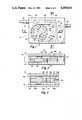
- FIG. 1represents schematically a plan view of the flow meter of this invention with the top plate removed.
- FIG. 2is a cross-section taken along the plane 2--2 of FIG. 1.
- FIG. 3is a cross-section taken along the plane 3--3 of FIG. 1.
- FIG. 4illustrates a variation of the design of FIG. 2.
- FIG. 5illustrates an alternative construction of the impeller vanes.
- FIG. 6illustrates schematically the electronic circuitry for displaying the total flow through the flow meter and the flow rate of fluid through the flow meter.
- FIGS. 1, 2 and 3there are shown in three views one embodiment of this invention.
- the flow meter of this inventionis indicated generally by the numeral 10. It comprises for example, a rectangular body, slab or plate 12 of thickness T with parallel faces. A circular opening 18 is machined through the block, with axis perpendicular to the faces, having a radius R. A cylindrical impeller 20 having an outer diameter slightly less than 2R, is adapted to be positioned inside this cylindrical cavity. It has a first axial boss 24 of length D on one side and a second axial boss 30 on the other side. The second boss can be as thick as the first boss or axial thinner. It serves to maintain a selected dimension of clearance 22 between the bottom surface of the impeller and the bottom cover plate 16.
- the impellerhas a plurality of spaced similar radial vanes 26 with corresponding spaces 28 between the vanes. These can be straightsided as will be shown in FIG. 5, or curved, as shown in FIG. 1.
- An inlet conduit 34is drilled through the block and intersects the circular cavity approximately tangentially, as shown in FIG. 1. Means 32 and 52 are provided for the attachment of suitable conduits into and out of the flow meter.
- a portion of the top face of the body 12 adjacent half of the circular cavityis depressed a selected depth D and has a width W, which is slightly less than the diameter of the cylindrical cavity.
- This volume 38 between the depressed surface 36 and the cover plate 14 on the topforms a channel for the outflow of fluid from the spaces between the vanes as the impeller, having one face substantially coplanar with the channel 36, rotates and leads to a channel 46 and to an outlet conduit 50 with corresponding fixture 52.
- central body 12which is a slab of uniform thickness T with plane parallel faces and has a cylindrical cavity cut from the top or the first face to the bottom face, part of the face 36 is cut away to form a channel for outlet flow of fluid from the impeller in accordance with arrows 54, through the channel 38 and to conduit 46 to the outlet conduit 50. Inflow of fluid is through the entrance conduit 34 which intersects the cylindrical cavity approximately tangentially.
- Two cover plates 14 and 16are provided to be positioned over and sealed to two faces of the body, which completely enclose the impeller.
- FIG. 1a volume 40 is cut out of the body from top to bottom for the purpose of positioning therein batteries and electronics for counting the revolutions of the impeller.
- a small diameter magnet 60is inserted into a drilled hole into one of the vanes, and as shown in FIG. 6 a suitable coil 64 (not shown in FIG. 1) is mounted in the space 38, for example, or on the outside of the top cover, with suitable electronic means to count the pulses generated each time the rotor impeller makes one complete revolution.
- This signalis generated in the coil 64 and amplified by a preamplifier 66.
- the voltageis generated when the magnet 60 moves laterally in direction 62 with respect to the coil 64.
- the output of the amplifiergoes to a digital counter 68 which continuously updates a binary number representing the total counts of rotation of the impeller.
- This binary number formed in 70goes to a binary coded decimal coder and to a decoder 72, and to a decimal display 74.
- a decimal numberis continually displayed in the display 74 which represents total rotations of the impeller.
- the blockBy use of a conventional digital clock 76, well known in the art, and a counter divider 78, which can be set or programmed, the block will count to a selected number of time units, and will then reset itself and reset the digital-to-binary coded decimal in box 70. This will reset the display to zero which will then count up from zero each time it is reset by the clock.
- the number that the display shows just before it is resetis then a number corresponding to the flow rate. That is, the total number of rotations of the impeller in a selected number of time units.
- this fluid flow meterdoes not greatly depend upon the shape of the impeller which can vary from a rounded contour as shown in FIG. 1 to a straight sided contour as shown in FIG. 5; where the vanes 26 are substantially parallel sided, and the space between 28 is substantially tapering.
- the magnet 60would be positioned in one of the vanes such as 26.
- FIG. 4there is shown a second embodiment, which is a variation of FIG. 2. What has been done here, has been to make a second depressed surface 36A a distance D below the bottom surface of the block, as a mirror image of the depressed surface 36 on the first side of the block.
- the rotorwould be similar except that the two bosses 24 and 30A would be of equal dimension.
- the inlet conduit 34would be positioned substantially in the midpoint between the two surfaces of the impeller so the flow of fluid would be symmetrically up and below the impeller through the two channels 38 and 38A, to a transverse opening through the body 48A and to an outlet conduit 50A.
Landscapes
- Physics & Mathematics (AREA)
- Fluid Mechanics (AREA)
- General Physics & Mathematics (AREA)
- Measuring Volume Flow (AREA)
Abstract
Description
Claims (7)
Priority Applications (1)
| Application Number | Priority Date | Filing Date | Title |
|---|---|---|---|
| US06/494,899US4489616A (en) | 1983-05-16 | 1983-05-16 | Digital fluid flow meter |
Applications Claiming Priority (1)
| Application Number | Priority Date | Filing Date | Title |
|---|---|---|---|
| US06/494,899US4489616A (en) | 1983-05-16 | 1983-05-16 | Digital fluid flow meter |
Publications (1)
| Publication Number | Publication Date |
|---|---|
| US4489616Atrue US4489616A (en) | 1984-12-25 |
Family
ID=23966418
Family Applications (1)
| Application Number | Title | Priority Date | Filing Date |
|---|---|---|---|
| US06/494,899Expired - Fee RelatedUS4489616A (en) | 1983-05-16 | 1983-05-16 | Digital fluid flow meter |
Country Status (1)
| Country | Link |
|---|---|
| US (1) | US4489616A (en) |
Cited By (25)
| Publication number | Priority date | Publication date | Assignee | Title |
|---|---|---|---|---|
| US4656873A (en)* | 1985-08-19 | 1987-04-14 | Stewart David A | Flow measuring device |
| US4666061A (en)* | 1984-03-20 | 1987-05-19 | Digmesa Ag Digitale Messtechnik | Measuring device for beverage dispenser lines |
| US5525214A (en)* | 1994-03-08 | 1996-06-11 | Recovery Engineering, Inc. | Filter cartridge for water treatment device |
| US5527451A (en)* | 1994-03-08 | 1996-06-18 | Recovery Engineering, Inc. | Water treatment device with volume totalization valve |
| US5536395A (en)* | 1993-03-22 | 1996-07-16 | Amway Corporation | Home water purification system with automatic disconnecting of radiant energy source |
| US5540107A (en)* | 1991-09-23 | 1996-07-30 | Futureflo Systems, Inc. | Liquid flow meter |
| WO1999007456A1 (en)* | 1997-08-08 | 1999-02-18 | Teledyne Industries, Inc. | Flowmeter system useable with water treatment device |
| US5876610A (en)* | 1997-03-19 | 1999-03-02 | Clack Corporation | Method and apparatus for monitoring liquid flow through an enclosed stream |
| US5935426A (en)* | 1997-08-08 | 1999-08-10 | Teledyne Industries, Inc., A California Corporation | Water treatment device with volumetric and time monitoring features |
| WO2001009569A1 (en)* | 1999-08-03 | 2001-02-08 | Perkins Craig R | Hydration-insuring system comprising suction-activated liquid-flow meter |
| EP1106228A1 (en)* | 1999-12-06 | 2001-06-13 | Brita GmbH | Device for measuring water flow throughput |
| US6502451B1 (en)* | 1998-04-30 | 2003-01-07 | Eugene Fourie | Leakage detector, a latching solenoid, a flow meter, and a liquid dispensing apparatus including same |
| USD498512S1 (en) | 2003-07-03 | 2004-11-16 | Clear Flow Corporation | Water filter |
| US20060004330A1 (en)* | 2004-02-20 | 2006-01-05 | Carlisle Jeffrey A | Automated fluid flow control system |
| USD533622S1 (en) | 2003-10-01 | 2006-12-12 | Water Pik, Inc. | End-of-faucet filter |
| USD541372S1 (en) | 2005-11-01 | 2007-04-24 | Clarity Filters Llc | Water filter |
| US20070090296A1 (en)* | 2005-09-29 | 2007-04-26 | Hoyt Reed W | Gear-Type Drink-O-Meter to Monitor Fluid Consumption |
| US7252757B2 (en) | 2002-09-09 | 2007-08-07 | Clarity Filters Llc | Faucet-mounted water filtration device including gate position sensor |
| US7258781B2 (en) | 2002-09-09 | 2007-08-21 | Clarity Filters Llc | Single-use long-life faucet-mounted water filtration devices |
| US7326334B2 (en) | 2003-10-01 | 2008-02-05 | Instapure Brands, Inc. | End-of-faucet filter |
| US20080296208A1 (en)* | 2005-09-07 | 2008-12-04 | Norio Ikeyama | Reverse Osmosis Filtration Devices with Rfid Tag-Powered Flow and Conductivity Meters |
| US20090320563A1 (en)* | 2006-03-13 | 2009-12-31 | Hydranautics | Device for measuring permeate flow and permeate conductivity of individual reverse osmosis membrane elements |
| US20140081218A1 (en)* | 2012-09-06 | 2014-03-20 | Memorial Sloan-Kettering Cancer Center | Intravenous device having a movable arrangement |
| US20140366643A1 (en)* | 2013-06-14 | 2014-12-18 | Roman L. Artiuch | Systems, devices, and methods for measuring and processing fuel meter measurements |
| US11480453B2 (en)* | 2018-04-18 | 2022-10-25 | Bwt Holding Gmbh | Turbine wheel meter |
Citations (3)
| Publication number | Priority date | Publication date | Assignee | Title |
|---|---|---|---|---|
| US3981194A (en)* | 1975-08-21 | 1976-09-21 | William O. Lehman | Flow meter system |
| US4173144A (en)* | 1978-04-03 | 1979-11-06 | Transdynamics | Low flow rate transducer construction |
| US4179924A (en)* | 1978-04-03 | 1979-12-25 | Chrysler Corporation | Mounting for paddlewheel photoelectric transducer |
- 1983
- 1983-05-16USUS06/494,899patent/US4489616A/ennot_activeExpired - Fee Related
Patent Citations (3)
| Publication number | Priority date | Publication date | Assignee | Title |
|---|---|---|---|---|
| US3981194A (en)* | 1975-08-21 | 1976-09-21 | William O. Lehman | Flow meter system |
| US4173144A (en)* | 1978-04-03 | 1979-11-06 | Transdynamics | Low flow rate transducer construction |
| US4179924A (en)* | 1978-04-03 | 1979-12-25 | Chrysler Corporation | Mounting for paddlewheel photoelectric transducer |
Cited By (41)
| Publication number | Priority date | Publication date | Assignee | Title |
|---|---|---|---|---|
| US4666061A (en)* | 1984-03-20 | 1987-05-19 | Digmesa Ag Digitale Messtechnik | Measuring device for beverage dispenser lines |
| US4656873A (en)* | 1985-08-19 | 1987-04-14 | Stewart David A | Flow measuring device |
| US5540107A (en)* | 1991-09-23 | 1996-07-30 | Futureflo Systems, Inc. | Liquid flow meter |
| US5536395A (en)* | 1993-03-22 | 1996-07-16 | Amway Corporation | Home water purification system with automatic disconnecting of radiant energy source |
| US5698091A (en)* | 1993-03-22 | 1997-12-16 | Amway Corporation | Home water purification system with filter end of life monitor |
| US5853572A (en)* | 1993-03-22 | 1998-12-29 | Amway Corporation | Home water purification system |
| EP0947231A1 (en)* | 1994-03-08 | 1999-10-06 | Recovery Engineering, Inc. | Water treatment device |
| US5525214A (en)* | 1994-03-08 | 1996-06-11 | Recovery Engineering, Inc. | Filter cartridge for water treatment device |
| US5527451A (en)* | 1994-03-08 | 1996-06-18 | Recovery Engineering, Inc. | Water treatment device with volume totalization valve |
| US5928504A (en)* | 1994-03-08 | 1999-07-27 | Recovery Engineering, Inc. | Faucet-mounted water treatment device |
| US6241103B1 (en) | 1994-03-08 | 2001-06-05 | Recovery Engineering, Inc. | Filter cartridge for water treatment device |
| US5876610A (en)* | 1997-03-19 | 1999-03-02 | Clack Corporation | Method and apparatus for monitoring liquid flow through an enclosed stream |
| EA002407B1 (en)* | 1997-08-08 | 2002-04-25 | Теледайн Индастриз, Инк. | Flowmeter system useable with water treatment device |
| US6517707B2 (en) | 1997-08-08 | 2003-02-11 | Water Pik, Inc. | Water treatment device with volumetric and time monitoring features |
| US6149801A (en)* | 1997-08-08 | 2000-11-21 | Water Pik, Inc,. | Water treatment device with volumetric monitoring features |
| US6926821B2 (en) | 1997-08-08 | 2005-08-09 | Water Pik, Inc. | Water treatment device with volumetric and time monitoring features |
| US6106705A (en)* | 1997-08-08 | 2000-08-22 | Teledyne Industries, Inc. | Water treatment device with volumetric and time monitoring features |
| US5935426A (en)* | 1997-08-08 | 1999-08-10 | Teledyne Industries, Inc., A California Corporation | Water treatment device with volumetric and time monitoring features |
| WO1999007456A1 (en)* | 1997-08-08 | 1999-02-18 | Teledyne Industries, Inc. | Flowmeter system useable with water treatment device |
| US6284129B1 (en)* | 1997-08-08 | 2001-09-04 | Water Pik, Inc. | Water treatment device with volumetric and time monitoring features |
| US6502451B1 (en)* | 1998-04-30 | 2003-01-07 | Eugene Fourie | Leakage detector, a latching solenoid, a flow meter, and a liquid dispensing apparatus including same |
| US6212959B1 (en) | 1999-08-03 | 2001-04-10 | Craig R. Perkins | Hydration insuring system comprising liquid-flow meter |
| WO2001009569A1 (en)* | 1999-08-03 | 2001-02-08 | Perkins Craig R | Hydration-insuring system comprising suction-activated liquid-flow meter |
| EP1106228A1 (en)* | 1999-12-06 | 2001-06-13 | Brita GmbH | Device for measuring water flow throughput |
| US7258781B2 (en) | 2002-09-09 | 2007-08-21 | Clarity Filters Llc | Single-use long-life faucet-mounted water filtration devices |
| US7252757B2 (en) | 2002-09-09 | 2007-08-07 | Clarity Filters Llc | Faucet-mounted water filtration device including gate position sensor |
| USD498512S1 (en) | 2003-07-03 | 2004-11-16 | Clear Flow Corporation | Water filter |
| USD533622S1 (en) | 2003-10-01 | 2006-12-12 | Water Pik, Inc. | End-of-faucet filter |
| US7326334B2 (en) | 2003-10-01 | 2008-02-05 | Instapure Brands, Inc. | End-of-faucet filter |
| US20060004330A1 (en)* | 2004-02-20 | 2006-01-05 | Carlisle Jeffrey A | Automated fluid flow control system |
| US7503903B2 (en)* | 2004-02-20 | 2009-03-17 | Fluidnet Corporation | Automated fluid flow control system |
| US20080296208A1 (en)* | 2005-09-07 | 2008-12-04 | Norio Ikeyama | Reverse Osmosis Filtration Devices with Rfid Tag-Powered Flow and Conductivity Meters |
| US8617397B2 (en)* | 2005-09-07 | 2013-12-31 | Hydranautics | Reverse osmosis filtration devices with RFID tag-powered flow and conductivity meters |
| US20070090296A1 (en)* | 2005-09-29 | 2007-04-26 | Hoyt Reed W | Gear-Type Drink-O-Meter to Monitor Fluid Consumption |
| US7851775B2 (en)* | 2005-09-29 | 2010-12-14 | The United States Of America As Represented By The Secretary Of The Army | Gear-type drink-o-meter to monitor fluid consumption |
| USD541372S1 (en) | 2005-11-01 | 2007-04-24 | Clarity Filters Llc | Water filter |
| US20090320563A1 (en)* | 2006-03-13 | 2009-12-31 | Hydranautics | Device for measuring permeate flow and permeate conductivity of individual reverse osmosis membrane elements |
| US20140081218A1 (en)* | 2012-09-06 | 2014-03-20 | Memorial Sloan-Kettering Cancer Center | Intravenous device having a movable arrangement |
| US20140366643A1 (en)* | 2013-06-14 | 2014-12-18 | Roman L. Artiuch | Systems, devices, and methods for measuring and processing fuel meter measurements |
| US9874468B2 (en)* | 2013-06-14 | 2018-01-23 | Dresser, Inc. | Systems, devices, and methods for measuring and processing fuel meter measurements |
| US11480453B2 (en)* | 2018-04-18 | 2022-10-25 | Bwt Holding Gmbh | Turbine wheel meter |
Similar Documents
| Publication | Publication Date | Title |
|---|---|---|
| US4489616A (en) | Digital fluid flow meter | |
| US5099699A (en) | Flow indicator or flowmeter | |
| US6012339A (en) | Tangential rotor flow rate meter | |
| US4641522A (en) | Bearing-less positive displacement flowmeter | |
| US4030357A (en) | Metering of fluid flows | |
| US3898883A (en) | Stator assembly for flowmeters and the like | |
| US4023410A (en) | Fluid flow meter | |
| EP0045588B1 (en) | Flow meter | |
| US4157660A (en) | Digital flowmeter | |
| US5275043A (en) | Positive displacement flowmeter | |
| US3443432A (en) | Flowmeter | |
| US3979957A (en) | Flow meter | |
| JPH03257329A (en) | Flowmeter | |
| JPS5839290B2 (en) | fluid flow meter | |
| US4007635A (en) | Fluid volume apparatus for measuring a fluid under pressure | |
| US3630082A (en) | Rotor measuring device for fluids | |
| CA2037993C (en) | Flow indicator or flowmeter | |
| PT8491T (en) | Ditch | |
| JPS6237132Y2 (en) | ||
| US5259244A (en) | Sinewave flowmeter | |
| US3518882A (en) | Positive displacement liquid meter | |
| JPS58127125A (en) | Flowmeter | |
| JP3258477B2 (en) | Flowmeter | |
| JPS57175913A (en) | Tap-water meter | |
| US5773718A (en) | Device for measuring liquid volume of the cylindrical piston meter type |
Legal Events
| Date | Code | Title | Description |
|---|---|---|---|
| AS | Assignment | Owner name:HEAD, JOHNSON & STEVENSON, A PROFESSIONAL CORP. OF Free format text:ASSIGNMENT OF ASSIGNORS INTEREST.;ASSIGNOR:PRIDDY, JERRY L.;REEL/FRAME:004195/0467 Effective date:19831123 Owner name:HEAD, JOHNSON & STEVENSON, A PROFESSIONAL CORP. OF Free format text:ASSIGNMENT OF ASSIGNORS INTEREST;ASSIGNOR:PRIDDY, JERRY L.;REEL/FRAME:004195/0467 Effective date:19831123 | |
| AS | Assignment | Owner name:PRIDDY, JERRY, L., Free format text:ASSIGNMENT OF ASSIGNORS INTEREST.;ASSIGNOR:HEAD, JOHNSON & STEVENSON;REEL/FRAME:004777/0448 Effective date:19850826 | |
| FPAY | Fee payment | Year of fee payment:4 | |
| FEPP | Fee payment procedure | Free format text:PAYOR NUMBER ASSIGNED (ORIGINAL EVENT CODE: ASPN); ENTITY STATUS OF PATENT OWNER: SMALL ENTITY | |
| FPAY | Fee payment | Year of fee payment:8 | |
| REMI | Maintenance fee reminder mailed | ||
| LAPS | Lapse for failure to pay maintenance fees | ||
| FP | Lapsed due to failure to pay maintenance fee | Effective date:19961225 | |
| STCH | Information on status: patent discontinuation | Free format text:PATENT EXPIRED DUE TO NONPAYMENT OF MAINTENANCE FEES UNDER 37 CFR 1.362 |