US4489449A - Trauma care wheeled stretcher - Google Patents
Trauma care wheeled stretcherDownload PDFInfo
- Publication number
- US4489449A US4489449AUS06/232,120US23212081AUS4489449AUS 4489449 AUS4489449 AUS 4489449AUS 23212081 AUS23212081 AUS 23212081AUS 4489449 AUS4489449 AUS 4489449A
- Authority
- US
- United States
- Prior art keywords
- supporting platform
- stretcher
- undercarriage
- patient
- backrest
- Prior art date
- Legal status (The legal status is an assumption and is not a legal conclusion. Google has not performed a legal analysis and makes no representation as to the accuracy of the status listed.)
- Expired - Fee Related
Links
- 208000014674injuryDiseases0.000titleclaimsdescription8
- 230000008733traumaEffects0.000titleclaimsdescription8
- 238000005086pumpingMethods0.000claimsdescription8
- 230000000994depressogenic effectEffects0.000claims1
- 238000012544monitoring processMethods0.000abstractdescription5
- 239000012530fluidSubstances0.000description7
- 230000007935neutral effectEffects0.000description3
- 230000009471actionEffects0.000description2
- 230000000881depressing effectEffects0.000description2
- 230000003213activating effectEffects0.000description1
- 230000008859changeEffects0.000description1
- 230000006835compressionEffects0.000description1
- 238000007906compressionMethods0.000description1
- 238000010276constructionMethods0.000description1
- 238000010586diagramMethods0.000description1
- 230000009977dual effectEffects0.000description1
- 230000036541healthEffects0.000description1
- 230000035939shockEffects0.000description1
Images


Classifications
- A—HUMAN NECESSITIES
- A61—MEDICAL OR VETERINARY SCIENCE; HYGIENE
- A61G—TRANSPORT, PERSONAL CONVEYANCES, OR ACCOMMODATION SPECIALLY ADAPTED FOR PATIENTS OR DISABLED PERSONS; OPERATING TABLES OR CHAIRS; CHAIRS FOR DENTISTRY; FUNERAL DEVICES
- A61G7/00—Beds specially adapted for nursing; Devices for lifting patients or disabled persons
- A—HUMAN NECESSITIES
- A61—MEDICAL OR VETERINARY SCIENCE; HYGIENE
- A61G—TRANSPORT, PERSONAL CONVEYANCES, OR ACCOMMODATION SPECIALLY ADAPTED FOR PATIENTS OR DISABLED PERSONS; OPERATING TABLES OR CHAIRS; CHAIRS FOR DENTISTRY; FUNERAL DEVICES
- A61G1/00—Stretchers
- A61G1/02—Stretchers with wheels
- A61G1/0206—Stretchers with wheels characterised by the number of supporting wheels if stretcher is extended
- A61G1/0212—2 pairs having wheels within a pair on the same position in longitudinal direction, e.g. on the same axis
- A—HUMAN NECESSITIES
- A61—MEDICAL OR VETERINARY SCIENCE; HYGIENE
- A61G—TRANSPORT, PERSONAL CONVEYANCES, OR ACCOMMODATION SPECIALLY ADAPTED FOR PATIENTS OR DISABLED PERSONS; OPERATING TABLES OR CHAIRS; CHAIRS FOR DENTISTRY; FUNERAL DEVICES
- A61G1/00—Stretchers
- A61G1/02—Stretchers with wheels
- A61G1/0237—Stretchers with wheels having at least one swivelling wheel, e.g. castors
- A61G1/0243—Stretchers with wheels having at least one swivelling wheel, e.g. castors with lockable swivel action, e.g. fixing castor in certain direction
- A—HUMAN NECESSITIES
- A61—MEDICAL OR VETERINARY SCIENCE; HYGIENE
- A61G—TRANSPORT, PERSONAL CONVEYANCES, OR ACCOMMODATION SPECIALLY ADAPTED FOR PATIENTS OR DISABLED PERSONS; OPERATING TABLES OR CHAIRS; CHAIRS FOR DENTISTRY; FUNERAL DEVICES
- A61G1/00—Stretchers
- A61G1/02—Stretchers with wheels
- A61G1/0287—Stretchers with wheels having brakes, e.g. slowing down and/or holding
- A—HUMAN NECESSITIES
- A61—MEDICAL OR VETERINARY SCIENCE; HYGIENE
- A61G—TRANSPORT, PERSONAL CONVEYANCES, OR ACCOMMODATION SPECIALLY ADAPTED FOR PATIENTS OR DISABLED PERSONS; OPERATING TABLES OR CHAIRS; CHAIRS FOR DENTISTRY; FUNERAL DEVICES
- A61G7/00—Beds specially adapted for nursing; Devices for lifting patients or disabled persons
- A61G7/002—Beds specially adapted for nursing; Devices for lifting patients or disabled persons having adjustable mattress frame
- A61G7/012—Beds specially adapted for nursing; Devices for lifting patients or disabled persons having adjustable mattress frame raising or lowering of the whole mattress frame
- A—HUMAN NECESSITIES
- A61—MEDICAL OR VETERINARY SCIENCE; HYGIENE
- A61G—TRANSPORT, PERSONAL CONVEYANCES, OR ACCOMMODATION SPECIALLY ADAPTED FOR PATIENTS OR DISABLED PERSONS; OPERATING TABLES OR CHAIRS; CHAIRS FOR DENTISTRY; FUNERAL DEVICES
- A61G7/00—Beds specially adapted for nursing; Devices for lifting patients or disabled persons
- A61G7/05—Parts, details or accessories of beds
- A61G7/0507—Side-rails
- A61G7/0508—Side-rails characterised by a particular connection mechanism
- A61G7/0509—Side-rails characterised by a particular connection mechanism sliding or pivoting downwards
- A—HUMAN NECESSITIES
- A61—MEDICAL OR VETERINARY SCIENCE; HYGIENE
- A61G—TRANSPORT, PERSONAL CONVEYANCES, OR ACCOMMODATION SPECIALLY ADAPTED FOR PATIENTS OR DISABLED PERSONS; OPERATING TABLES OR CHAIRS; CHAIRS FOR DENTISTRY; FUNERAL DEVICES
- A61G7/00—Beds specially adapted for nursing; Devices for lifting patients or disabled persons
- A61G7/05—Parts, details or accessories of beds
- A61G7/0528—Steering or braking devices for castor wheels
Definitions
- This inventionrelates generally to a wheeled stretcher with an adjustable patient supporting platform and more particularly to such a stretcher with duplicate adjustment controls positioned on each side of the patient supporting platform so that an attendant may adjust the position of the patient supporting platform without leaving the side of a patient on the stretcher.
- a wheeled stretchersometimes referred to as a Gurney
- this type of stretchermay function as a transport vehicle, an examining table, and/or an operating table.
- the patient supporting platform of this type of stretcheris usually adjustable in a vertical direction and may be tilted to a head-down (Trendlenburg) or a head-up (reverse Trendlenburg) position by hydraulic cylinders actuated by means of a foot pedal operated pumping device.
- Brake meansis also provided to lock the wheels when the stretcher is not being used to transport the patient.
- the stretcheris also provided with a pivotally supported backrest with control means for varying the adjusted (Fowler) position of the backrest. Examples of this well known type of stretcher are disclosed in U.S. Pat. Nos. 4,175,783; 3,820,838; 3,393,004; 3,341,246; and 3,050,745.
- a foot pedal hydraulic pumping leveris positioned at each side of the stretcher for operating hydraulic cylinders for raising the patient supporting platform.
- a foot operated brake pedalis positioned at each side of the undercarriage of the stretcher and is operable to apply the brakes to the wheels of the stretcher by an attendant while positioned at either side of the stretcher.
- Control meansis positioned at each side of the patient supporting platform and is operable by the attendant positioned at either side of the platform for selectively lowering and/or tilting the patient supporting platform, as required.
- Backrest controlsare also provided at each side of the patient supporting platform so that the position of the patient may be varied by the attendant while remaining at the side of the stretcher.
- a gas springis provided to aid in adjusting the backrest to various Fowler positions.
- FIG. 1is a perspective elevational view of one side of the stretcher of the present invention
- FIG. 2is an isometric view of the undercarriage structure of the stretcher with the patient supporting platform removed;
- FIG. 3is a somewhat schematic diagram illustrating the hydraulic system for controlling the vertical and tilting positions of the patient supporting platform
- FIG. 4is a fragmentary and somewhat schematic view of the head end portion of the patient supporting platform and illustrating the manner in which the tilting of the backrest is controlled;
- FIG. 5is a vertical sectional view through one of the hydraulic lift cylinders supporting one end of the patient supporting platform;
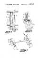
- FIG. 6is a vertical sectional view through the support for one of the caster wheels, showing the manner in which the brake operates to stop rotation of the wheel;
- FIG. 7is a somewhat schematic isometric view illustrating the manner in which the brake controls are operated and supported on each side of the stretcher.
- the trauma care wheeled stretcher of the present inventiongenerally includes a rectangular patient supporting platform, broadly indicated at 10 and including head and foot ends and opposite sides.
- the patient supporting platform 10includes a fixed body supporting portion 11 and a backrest portion 12 which is pivotally connected, as at 13, to one end of the fixed body portion 11 and is supported for angular adjustment, in a manner to be presently described.
- Self-storing side rails 14, 14'are supported at opposite sides of the platform 10 for movement between the raised position illustrated by rail 14 and the lowered position, illustrated by the rail 14'.
- a patient support pad or mattress, not shown,is normally provided on the upper surface of the platform 10 to provide a comfortable support for the patient.
- An undercarriage structure, broadly indicated at 15,is positioned below the platform 10, is of generally the same width as the platform 10, and includes corresponding head and foot ends and opposite sides.
- the undercarriage structure 15includes a head-end cross frame 16, a foot-end cross frame 17 and a central support frame 18 connected at opposite ends to the cross frames 16, 17.
- a caster wheel 20is supported, in a manner to be presently described, at each corner of the undercarriage 15 so that the stretcher may be moved from place to place when it is necessary to transport the patient.
- Hydraulic meansis carried by the undercarriage for supporting the patient supporting platform 10 for vertical movement relative to the undercarriage 15.
- the hydraulic meansincludes a head-end support column, broadly indicated at 21, and a foot-end support column, broadly indicated at 22, in FIGS. 1 and 2.
- the support columns 21, 22are identical in construction and the details of the support column 21 will be described with reference to FIG. 5 while the corresponding parts of the support column 22 will bear the same reference numerals with the prime notation added.
- the support column 21(FIG. 5) includes an outer telescoping guide sleeve 23, the lower portion of which is fixed on the frame 18 and the upper portion of which supports an upper guide sleeve 24 for vertical sliding movement therein.
- Adjustable guide pins 25are provided at the upper end of the guide sleeve 23 and the lower end of the guide sleeve 24 for guiding the vertical movement of the upper guide sleeve 24.
- a hydraulic cylinder 26is supported at its lower end in the guide sleeve 23 and its upper end is connected to a support tube 29 which is, in turn, suitably connected to the head-end portion of the patient supporting platform 10.
- Foot pedal hydraulic pumping meansincluding folding action foot pedals 30, 30' is positioned at each side of the undercarriage 15 for operation by an attendant positioned at either side of the patient supporting platform 10.
- the foot pedal hydraulic pumping meansalso includes operating levers 31, 31' connected at one end to the respective foot pedals 30, 30' and connected at their opposite ends to an operating shaft 32, pivotally supported intermediate its ends on the frame 18.
- Levers 33, 33'are fixed at their upper ends on the operating shaft 32 and are pivotally connected at their lower ends to a substantially U-shaped pump actuator 34 which surrounds a single shaft dual chamber hydraulic pump 35.
- a spring 36normally urges the U-shaped pump actuator 34 to the left in FIG. 3 so that the foot pedals 30, 30' are normally maintained in a raised position.
- a cross frame 40is connected at opposite ends to the pump actuator 34 and the medial portion is connected to the operating rod of the hydraulic pump 35, for purposes to be presently described.
- One-way check valves 41, 42 and 41', 42'are provided at opposite sides of the pump 35.
- a hydraulic line 43is connected at one end to the check valve 41 and its opposite end is connected to a reservoir 45 containing hydraulic fluid.
- a hydraulic line 43'is connected at one end to the check valve 41' and its opposite end is connected to the reservoir 45.
- a hydraulic line 46is connected at one end to the check valve 42 and its other end is connected to the lower end of the hydraulic lift cylinder 26.
- a hydraulic line 46'is connected at one end to the check valve 42' and its other end is connected to the lower end of the lift hydraulic cylinder 26'.
- One end of a hydraulic line 47is connected to the upper end of the lift cylinder 26 and the opposite end is connected to the reservoir 45.
- One end of a hydraulic line 47'is connected to the upper end of the lift cylinder 26' and the opposite end is connected to the reservoir 45.
- a normally closed control valve 50is provided for controlling the lowering of the lift cylinder 26 at the head-end of the stretcher and a normally closed control valve 50' is provided for controlling the lowering of the lift cylinder 26' at the foot-end of the stretcher.
- the control valve 50is connected to the line 46 by a hydraulic line 51 and the valve 50' is connected to the line 46' by a hydraulic line 51'.
- Hydraulic lines 52, 52'are connected to the respective valves 50, 50' and are commonly joined to a return line 53 which is, in turn, connected to the reservoir 45.
- Patient supporting platform lowering and tilting control meansis positioned at each side of and below the level of the patient supporting platform 10 and is illustrated as Trendlenburg pushbutton control levers 55, 55' and reverse Trendlenburg pushbutton control levers 56, 56'.
- Control cables 60, 60'are connected at one end to the respective pushbutton control levers 55, 55' and their opposite ends are connected to a valve control toggle lever 61 for operation of the valve 50, in a manner to be presently described.
- Control cables 62, 62'are suitably connected at one end to the respective pushbutton levers 56, 56' and their other ends are connected to a valve control toggle lever 63 which operates the valve 50', in a manner to be presently described.
- the patient supporting platform 10can be raised by an attendant positioned at either side of the stretcher by merely placing the foot on the corresponding foot pedal 30, 30' and applying a pumping action so that the pump 35 simultaneously supplies hydraulic fluid under pressure through the lines 46, 46' and to the lower ends of the lift cylinders 26, 26' to extend the piston rods therein and lift the patient supporting platform 10 to the desired height.
- the patient supporting platform 10can be immediately moved to a Trendlenburg position by the attendant while remaining at either side of the stretcher.
- the attendantTo immediately move the patient supporting platform 10 to the Trendlenburg position, the attendant merely pushes the pushbutton lever 55 or 55' corresponding with the side of the stretcher on which the attendant is positioned and the corresponding control cable 60, 60' will move the valve 50 to the open position so that the head-end lift cylinder 26 is immediately lowered and the hydraulic fluid can flow back through the line 46, line 51, valve 50, line 52, line 53, and return to the reservoir 45.
- the attendantWhen the head-end of the platform 10 is lowered to the position desired, the attendant will merely release the corresponding pushbutton control 55 or 55' so that the valve 50 will immediately move back to the normally closed position and prevent further flow of the hydraulic fluid from the head-end lift cylinder 26 and to the reservoir 45.
- the patient supporting platform 10may be immediately tilted to the reverse Trendlenburg position by the attendant depressing the pushbutton lever 56, 56' on the side of the stretcher on which the attendant is positioned.
- the corresponding control cable 62 or 62'will operate the toggle lever 63 to move the valve 50' to the open position so that the foot-end lift cylinder 26' will be immediately lowered and as the hydraulic fluid can then flow back through the line 46', line 51', valve 50', line 52', line 53 and return to the reservoir 45.
- the attendantwill simultaneously depress the pushbuttons 55, 56 or 55', 56' at either side of the stretcher so that both of the normally closed valves 50, 50' are moved to the open position and the hydraulic fluid can flow from the lower ends of both lift cylinders 26 and 26' and return to the reservoir 45.
- the valves 50, 50'are immediately moved to the closed position to stop the flow of hydraulic fluid from the lift cylinders 26, 26' and immediately stop the downward vertical movement of the patient supporting platform 10.
- Brake meansis associated with each of the caster wheels 20 and includes a foot operated brake control 70, 70' positioned at each side of the undercarriage 15 so that the brake means can be applied to the caster wheels by an attendant positioned at either side of the patient supporting platform 10.
- the foot operated brake controls 70, 70'are fixed on the corresponding ends of respective control shafts 71, 71' (FIG. 7) which are supported for rotation in the corresponding cross frames 16, 17 of the undercarriage 15.
- Control cams 72are provided on each end of each of the control shafts 71, 71' and operate the brake and swivel functions, in a manner to be presently described.
- An interconnect link 73is connected at opposite ends to lever arms on the corresponding control shafts 71, 71' so that when one of the foot operated brake controls 70, 70' is operated to impart corresponding rotation to one of the control shafts 71, 71', the corresponding control shaft will be rotated in the same identical manner.
- Each caster wheel 20is supported for rotation on an axle 75 (FIG. 6) which is fixed at opposite ends in the lower ends of a bifurcated wheel support 76.
- the upper end of the wheel support 76is mounted to swivel on a vertical control shaft 77 which is supported in a wheel housing 78.
- the wheel housing 78is fixed to opposite ends of each of the cross frames 16, 17.
- a ball bearing 80is provided between the housing 78 and the wheel support 76 so that the wheel 20 is free to swivel when the control shaft 77 is in a certain position, in a manner to be presently described.
- the lower end of the control shaft 77is provided with a brake disc 81 which is adapted to at times engage a brake pad 82 riding on a portion of the wheel 20 and pivotally supported at one end as at 83.
- a compression spring 84normally maintains the control shaft 77 in an uppermost position so that the upper end is resiliently urged against the control cam 72.
- Cam notches 86are provided in the control cam 72 and are moved into engagement with the upper end of the control shaft 77, depending upon the rotational position of the control cam 72 and the position of the foot operated brake controls 70, 70'.
- one of the foot operated brake controls 70, 70'is rocked in a counterclockwise direction so that the upper end of the control shaft 77 is positioned in the deep cam notch 86 (FIG. 6) in the cam 72 and the spring 84 will raise the control shaft 77 so that the disc 81 engages the horizontal portion of the wheel support 76, thereby preventing swivel movement of the wheel support 76, relative to the housing 78.
- the pivoted backrest 12is provided with position control means, broadly indicated at 90 and illustrated in the form of a gas spring, for maintaining the backrest 12 in the desired adjusted position and for aiding in moving the backrest 12 from one position to another position.
- Manually operable control meansin the form of pull handles 91, 91', are positioned at opposite sides of the upper ends of the backrest 12 and are operable to control the gas spring 90.
- the gas spring 90is pivotally supported at one end on a support bracket 93 (FIG. 4) fixed to the stationary portion 11 of the patient supporting platform 10.
- the other end of the gas spring 90is pivotally connected to the lower end of an operating lever 94, the upper end of which is fixed to the backrest 12.
- a control lever 95is supported for pivotal movement on one end of the gas spring 90 and is normally maintained in the neutral position shown in FIG. 4.
- the control lever 95may be moved to the activating position (so that the gas spring 90 may be moved) by a main control cable 96.
- the main control cable 96is connected to branch control cables 97, 97', which are, in turn, connected to the corresponding pull handles 91, 91'.
- the control lever 95When the pull handles 91, 91' are not grasped and pulled, the control lever 95 is in the neutral position so that the gas spring 90 supports the backrest 12 in the adjusted position.
- the position of the backrest 12may be adjusted manually by the attendant and the gas spring 90 will assist the attendant in making the adjustment.
- the corresponding pull handle 91, 91'is released and the control lever 95 will move to the neutral position and maintain the position of the gas spring 90 and the adjusted position of the backrest 12.
- wire storage utility baskets 100, 100'are supported at opposite sides of the undercarriage 15 and extending along the main frame 18 and between the cross frames 16, 17. These wire storage utility baskets 100, 100' may be used to store medical supplies and the like which may be needed in treatment of the patient and will be readily accessible to an attendant while standing at either side of the stretcher.
- the stretcher of the present inventionthus includes duplicate adjustment controls positioned on each side of the patient supporting platform so that an attendant may adjust the position of the patient supporting platform without leaving the side of a patient supported on the stretcher.
- the foot pedals 30, 30'are easily accessible from either side of the stretcher and may be operated by the attendant for raising the position of the patient supporting platform 10.
- the pushbuttons 55, 55' and 56, 56'are readily accessible by the attendant at either side of the stretcher and may be operated to lower or immediately tilt the patient supporting platform 10 to the Trendlenburg or reverse Trendlenburg positions, as desired.
- the foot operated brake controls 70, 70'are also positioned at opposite sides of the stretcher for easy access by an attendant standing on either side of the stretcher and are operable to control the conditions of the wheels 20.
- the pull handles 90, 90'are also positioned at either side of the stretcher so that adjustment of the backrest 12 may be carried out by an attendant positioned at either side of the stretcher. With the stretcher of the present invention, the attendant may remain at either side of the stretcher and still make any necessary adjustments to the position of the stretcher without the necessity of leaving the side of the patient.
Landscapes
- Health & Medical Sciences (AREA)
- Life Sciences & Earth Sciences (AREA)
- Animal Behavior & Ethology (AREA)
- General Health & Medical Sciences (AREA)
- Public Health (AREA)
- Veterinary Medicine (AREA)
- Nursing (AREA)
- Invalid Beds And Related Equipment (AREA)
Abstract
Description
Claims (4)
Priority Applications (1)
| Application Number | Priority Date | Filing Date | Title |
|---|---|---|---|
| US06/232,120US4489449A (en) | 1981-02-06 | 1981-02-06 | Trauma care wheeled stretcher |
Applications Claiming Priority (1)
| Application Number | Priority Date | Filing Date | Title |
|---|---|---|---|
| US06/232,120US4489449A (en) | 1981-02-06 | 1981-02-06 | Trauma care wheeled stretcher |
Publications (1)
| Publication Number | Publication Date |
|---|---|
| US4489449Atrue US4489449A (en) | 1984-12-25 |
Family
ID=22871950
Family Applications (1)
| Application Number | Title | Priority Date | Filing Date |
|---|---|---|---|
| US06/232,120Expired - Fee RelatedUS4489449A (en) | 1981-02-06 | 1981-02-06 | Trauma care wheeled stretcher |
Country Status (1)
| Country | Link |
|---|---|
| US (1) | US4489449A (en) |
Cited By (49)
| Publication number | Priority date | Publication date | Assignee | Title |
|---|---|---|---|---|
| USD289992S (en) | 1984-07-27 | 1987-05-26 | Colson Equipment, Inc. | Stretcher |
| US4669136A (en)* | 1985-04-02 | 1987-06-02 | Med-Con Of Georgia, Inc. | Combination hospital bed and surgical table |
| US4723808A (en)* | 1984-07-02 | 1988-02-09 | Colson Equipment Inc. | Stretcher foot pedal mechanical linkage system |
| US4751755A (en)* | 1980-02-14 | 1988-06-21 | Siemens Medical Systems, Inc. | Patient trolley with improved tiltable backrest |
| US4768241A (en)* | 1987-02-24 | 1988-09-06 | Beney Daniel R | Self contained, mobile intensive care bed structure |
| US4928332A (en)* | 1988-11-07 | 1990-05-29 | Ralph Ogden | Adjustable mattress foundation for beds |
| US5022105A (en)* | 1989-08-04 | 1991-06-11 | Michael Catoe | Mobile lift-assisted patient transport device for field use |
| US5083625A (en)* | 1990-07-02 | 1992-01-28 | Bleicher Joel N | Powdered maneuverable hospital cart |
| US5317769A (en)* | 1992-11-10 | 1994-06-07 | Hill-Rom Company, Inc. | Hospital bed |
| FR2728527A1 (en)* | 1994-12-27 | 1996-06-28 | Sotectub | Hospital trolley wheel braking and frame raising and lowering controls |
| GB2305419A (en)* | 1995-09-21 | 1997-04-09 | Juergen Michael Knapp | Lifting Pillars |
| WO1999003418A3 (en)* | 1997-07-14 | 1999-04-08 | Hill Rom Co Inc | Surgical stretcher |
| EP1095647A1 (en)* | 1999-10-29 | 2001-05-02 | Hermann Bock GmbH | Bed with device for adjusting the height |
| WO2001074198A1 (en)* | 2000-03-31 | 2001-10-11 | Linak A/S | A lifting column, preferably for height adjustable furniture, such as beds and tables |
| US6345854B1 (en) | 1998-12-23 | 2002-02-12 | Vt Holdings Ii, Inc. | Mechanism for synchronizing and controlling multiple actuators of a slide out room of mobile living quarters |
| US6390213B1 (en) | 1998-11-16 | 2002-05-21 | Joel N. Bleicher | Maneuverable self-propelled cart |
| US6401278B1 (en)* | 1997-09-29 | 2002-06-11 | Huntleigh Technology, Plc | Accident and emergency trolley |
| US6421854B1 (en) | 2000-02-18 | 2002-07-23 | Hill-Rom Services, Inc. | Imaging stretcher |
| US6499156B1 (en)* | 2001-03-05 | 2002-12-31 | Tracy L. Dirst | Examination table system |
| US6575052B2 (en)* | 2001-07-31 | 2003-06-10 | Ge Medical Systems Global Technology Company, Llc | Pedal mechanism for operating brake and directional lock on lever-operated caster wheels |
| US6578215B1 (en) | 2000-09-29 | 2003-06-17 | Hill-Rom Services, Inc. | Surgery stretcher |
| US6643873B2 (en) | 2001-04-27 | 2003-11-11 | Hill-Rom Services, Inc. | Patient support apparatus having auto contour |
| US20040088792A1 (en)* | 2002-08-30 | 2004-05-13 | O'krangley Jason M. | Transportatable medical apparatus |
| US20040093668A1 (en)* | 1996-04-12 | 2004-05-20 | Heimbrock Richard H. | Pedal arrangement for stretcher apparatus |
| US20040111798A1 (en)* | 2000-12-26 | 2004-06-17 | Shigeyuki Matunaga | Stretcher |
| US20040201204A1 (en)* | 2003-04-08 | 2004-10-14 | Haire A. Ralph | Cart for inflatable beds |
| US20060016008A1 (en)* | 2004-07-26 | 2006-01-26 | Choi Byung K | Stretcher with gear mechanism for adjustable height |
| JP2006515995A (en)* | 2002-09-06 | 2006-06-15 | ヒル−ロム サービシーズ,インコーポレイティド | Hospital bed |
| US20060162077A1 (en)* | 2004-08-11 | 2006-07-27 | Stryker Corporation | Gas bottle support for a gurney or stretcher frame |
| US20070017029A1 (en)* | 2005-04-06 | 2007-01-25 | Wurdeman Byron W | Hospital beds with a rotating sleep surface that can translate into a chair configuration |
| WO2007123571A1 (en)* | 2006-04-26 | 2007-11-01 | Stryker Corporation | Ambulance cot docking assembly and patient support articulation features |
| US20080276372A1 (en)* | 2004-09-24 | 2008-11-13 | Stryker Corporation | Ambulance cot with retractable head section and control system therefor |
| US20090224133A1 (en)* | 2008-02-29 | 2009-09-10 | Gass Stephen F | Mobile base for a table saw |
| US20090307844A1 (en)* | 2008-06-13 | 2009-12-17 | Hornbach David W | Transport Apparatus |
| US7926131B2 (en) | 1999-12-29 | 2011-04-19 | Hill-Rom Services, Inc. | Hospital bed |
| US8016301B2 (en) | 2006-01-19 | 2011-09-13 | Hill-Rom Services, Inc. | Stretcher foot pedal arrangement |
| US8511693B2 (en) | 2005-03-31 | 2013-08-20 | Sd3, Llc | Mobile base for a table saw |
| CN103705350A (en)* | 2014-02-17 | 2014-04-09 | 宿州市江海医疗器械有限公司 | Hydraulic lifting flatcar |
| WO2013158580A3 (en)* | 2012-04-17 | 2014-04-10 | Ferno-Washington, Inc. | Adjustable head rest assemblies for patient positioning and patient support apparatus including adjustable head rest assemblies |
| USRE44884E1 (en) | 2004-09-24 | 2014-05-13 | Stryker Corporation | Ambulance cot with pinch safety feature |
| CN104688443A (en)* | 2015-03-25 | 2015-06-10 | 彭文献 | Electric wheeled stretcher |
| US9468574B1 (en) | 2015-02-03 | 2016-10-18 | James Phillips | Ambulatory stretcher with patient lifting measures |
| CN106473869A (en)* | 2016-12-17 | 2017-03-08 | 黄萍 | A kind of medical stretcher |
| US9603764B2 (en) | 2014-02-11 | 2017-03-28 | Medline Industries, Inc. | Method and apparatus for a locking caster |
| US9918888B2 (en)* | 2014-03-21 | 2018-03-20 | Medline Industries, Inc. | Locking mechanism with pivotable foot actuation lever |
| US10022283B2 (en)* | 2010-08-17 | 2018-07-17 | Kevin Wilson Lawless | Platform for patient conveying equipment |
| US10420684B2 (en)* | 2013-06-14 | 2019-09-24 | Ferno-Washington, Inc. | Assisted lifting devices for roll-in-cots |
| CN112494225A (en)* | 2020-11-26 | 2021-03-16 | 中国人民解放军陆军军医大学 | Portable field emergency bed |
| US11324648B2 (en)* | 2018-11-21 | 2022-05-10 | Stryker Corporation | Patient transport apparatus with steer lock assembly |
Citations (19)
| Publication number | Priority date | Publication date | Assignee | Title |
|---|---|---|---|---|
| US1626091A (en)* | 1924-02-07 | 1927-04-26 | Jesse W Macklin | Osteopathic operating table |
| US2217783A (en)* | 1938-06-09 | 1940-10-15 | F O Schoedinger | Operating table |
| US2632898A (en)* | 1950-08-08 | 1953-03-31 | Albert J Macdonald | Invalid bed with fluid operated sections |
| US2819475A (en)* | 1954-04-07 | 1958-01-14 | Sangfabriken Ab | Hospital beds or the like |
| US3304116A (en)* | 1965-03-16 | 1967-02-14 | Stryker Corp | Mechanical device |
| US3317931A (en)* | 1965-08-13 | 1967-05-09 | Royalmetal Corp | Adjustable bed |
| US3579671A (en)* | 1968-06-07 | 1971-05-25 | Stiegelmeyer & Co Gmbh | Adjustable bed |
| GB1274324A (en)* | 1969-11-13 | 1972-05-17 | Masterpeace Products Ltd | Improvements in or relating to beds or the like |
| US3733623A (en)* | 1970-11-24 | 1973-05-22 | Nestbit Evans & Comp Ltd | Hospital beds |
| US3739406A (en)* | 1970-09-16 | 1973-06-19 | Stiegelmeyer & Co Gmbh | Adjustable bed |
| US3742527A (en)* | 1972-03-01 | 1973-07-03 | Unlimited Dev Inc | Hospital bed |
| US3814414A (en)* | 1972-07-24 | 1974-06-04 | H Chapa | Medical examination table |
| US3827089A (en)* | 1971-09-16 | 1974-08-06 | W Grow | Turnover bed assembly |
| CH570802A5 (en)* | 1973-03-21 | 1975-12-31 | Bremshey Ag | Castor wheel locking system for hospital bed - foot pedal actuated lever system braking all wheels |
| DE2525596A1 (en)* | 1975-06-09 | 1976-12-16 | Stahl Vogel Wilhelm Vogel | Hospital bed adjustable for height and inclination - is actuated by hydraulic jack and locked via Bowden cable control |
| US4002330A (en)* | 1975-12-05 | 1977-01-11 | Johansson Hans Arne V | Patient supporting table |
| US4023849A (en)* | 1974-10-08 | 1977-05-17 | G. D. Searle & Co. | Stretcher trolleys |
| US4097941A (en)* | 1977-05-17 | 1978-07-04 | Merkel Jerome L | Emergency cot with spring-biased retractable wheel carriage |
| US4231124A (en)* | 1978-04-01 | 1980-11-04 | J. Nesbit-Evans & Co. Ltd. | Hospital beds |
- 1981
- 1981-02-06USUS06/232,120patent/US4489449A/ennot_activeExpired - Fee Related
Patent Citations (19)
| Publication number | Priority date | Publication date | Assignee | Title |
|---|---|---|---|---|
| US1626091A (en)* | 1924-02-07 | 1927-04-26 | Jesse W Macklin | Osteopathic operating table |
| US2217783A (en)* | 1938-06-09 | 1940-10-15 | F O Schoedinger | Operating table |
| US2632898A (en)* | 1950-08-08 | 1953-03-31 | Albert J Macdonald | Invalid bed with fluid operated sections |
| US2819475A (en)* | 1954-04-07 | 1958-01-14 | Sangfabriken Ab | Hospital beds or the like |
| US3304116A (en)* | 1965-03-16 | 1967-02-14 | Stryker Corp | Mechanical device |
| US3317931A (en)* | 1965-08-13 | 1967-05-09 | Royalmetal Corp | Adjustable bed |
| US3579671A (en)* | 1968-06-07 | 1971-05-25 | Stiegelmeyer & Co Gmbh | Adjustable bed |
| GB1274324A (en)* | 1969-11-13 | 1972-05-17 | Masterpeace Products Ltd | Improvements in or relating to beds or the like |
| US3739406A (en)* | 1970-09-16 | 1973-06-19 | Stiegelmeyer & Co Gmbh | Adjustable bed |
| US3733623A (en)* | 1970-11-24 | 1973-05-22 | Nestbit Evans & Comp Ltd | Hospital beds |
| US3827089A (en)* | 1971-09-16 | 1974-08-06 | W Grow | Turnover bed assembly |
| US3742527A (en)* | 1972-03-01 | 1973-07-03 | Unlimited Dev Inc | Hospital bed |
| US3814414A (en)* | 1972-07-24 | 1974-06-04 | H Chapa | Medical examination table |
| CH570802A5 (en)* | 1973-03-21 | 1975-12-31 | Bremshey Ag | Castor wheel locking system for hospital bed - foot pedal actuated lever system braking all wheels |
| US4023849A (en)* | 1974-10-08 | 1977-05-17 | G. D. Searle & Co. | Stretcher trolleys |
| DE2525596A1 (en)* | 1975-06-09 | 1976-12-16 | Stahl Vogel Wilhelm Vogel | Hospital bed adjustable for height and inclination - is actuated by hydraulic jack and locked via Bowden cable control |
| US4002330A (en)* | 1975-12-05 | 1977-01-11 | Johansson Hans Arne V | Patient supporting table |
| US4097941A (en)* | 1977-05-17 | 1978-07-04 | Merkel Jerome L | Emergency cot with spring-biased retractable wheel carriage |
| US4231124A (en)* | 1978-04-01 | 1980-11-04 | J. Nesbit-Evans & Co. Ltd. | Hospital beds |
Cited By (89)
| Publication number | Priority date | Publication date | Assignee | Title |
|---|---|---|---|---|
| US4751755A (en)* | 1980-02-14 | 1988-06-21 | Siemens Medical Systems, Inc. | Patient trolley with improved tiltable backrest |
| US4723808A (en)* | 1984-07-02 | 1988-02-09 | Colson Equipment Inc. | Stretcher foot pedal mechanical linkage system |
| USD289992S (en) | 1984-07-27 | 1987-05-26 | Colson Equipment, Inc. | Stretcher |
| US4669136A (en)* | 1985-04-02 | 1987-06-02 | Med-Con Of Georgia, Inc. | Combination hospital bed and surgical table |
| US4768241A (en)* | 1987-02-24 | 1988-09-06 | Beney Daniel R | Self contained, mobile intensive care bed structure |
| US4928332A (en)* | 1988-11-07 | 1990-05-29 | Ralph Ogden | Adjustable mattress foundation for beds |
| US5022105A (en)* | 1989-08-04 | 1991-06-11 | Michael Catoe | Mobile lift-assisted patient transport device for field use |
| US5083625A (en)* | 1990-07-02 | 1992-01-28 | Bleicher Joel N | Powdered maneuverable hospital cart |
| US5317769A (en)* | 1992-11-10 | 1994-06-07 | Hill-Rom Company, Inc. | Hospital bed |
| FR2728527A1 (en)* | 1994-12-27 | 1996-06-28 | Sotectub | Hospital trolley wheel braking and frame raising and lowering controls |
| GB2305419A (en)* | 1995-09-21 | 1997-04-09 | Juergen Michael Knapp | Lifting Pillars |
| GB2305419B (en)* | 1995-09-21 | 1999-11-03 | Juergen Michael Knapp | Lifting pillar |
| US20040093668A1 (en)* | 1996-04-12 | 2004-05-20 | Heimbrock Richard H. | Pedal arrangement for stretcher apparatus |
| US6772460B2 (en)* | 1996-04-12 | 2004-08-10 | Hill-Rom Services, Inc. | Pedal arrangement for stretcher apparatus |
| WO1999003418A3 (en)* | 1997-07-14 | 1999-04-08 | Hill Rom Co Inc | Surgical stretcher |
| US6076208A (en)* | 1997-07-14 | 2000-06-20 | Hill-Rom, Inc. | Surgical stretcher |
| US6108840A (en)* | 1997-07-14 | 2000-08-29 | Hill-Rom, Inc. | Head rest for a patient support |
| US6202231B1 (en) | 1997-07-14 | 2001-03-20 | Hill-Rom, Inc. | Surgical stretcher |
| US6249923B1 (en) | 1997-07-14 | 2001-06-26 | Hill-Rom, Inc. | Adjustable head rest for a patient support |
| US6314597B2 (en) | 1997-07-14 | 2001-11-13 | Hill-Rom Services, Inc. | Stretcher foot pedal |
| US6401278B1 (en)* | 1997-09-29 | 2002-06-11 | Huntleigh Technology, Plc | Accident and emergency trolley |
| US6390213B1 (en) | 1998-11-16 | 2002-05-21 | Joel N. Bleicher | Maneuverable self-propelled cart |
| US6345854B1 (en) | 1998-12-23 | 2002-02-12 | Vt Holdings Ii, Inc. | Mechanism for synchronizing and controlling multiple actuators of a slide out room of mobile living quarters |
| EP1095647A1 (en)* | 1999-10-29 | 2001-05-02 | Hermann Bock GmbH | Bed with device for adjusting the height |
| US8151387B2 (en) | 1999-12-29 | 2012-04-10 | Hill-Rom Services, Inc. | Hospital bed frame |
| US9009893B2 (en) | 1999-12-29 | 2015-04-21 | Hill-Rom Services, Inc. | Hospital bed |
| US7926131B2 (en) | 1999-12-29 | 2011-04-19 | Hill-Rom Services, Inc. | Hospital bed |
| US10251797B2 (en) | 1999-12-29 | 2019-04-09 | Hill-Rom Services, Inc. | Hospital bed |
| US6615430B2 (en) | 2000-02-18 | 2003-09-09 | Hill-Rom Services, Inc. | Imaging stretcher |
| US6421854B1 (en) | 2000-02-18 | 2002-07-23 | Hill-Rom Services, Inc. | Imaging stretcher |
| US6701554B2 (en) | 2000-02-18 | 2004-03-09 | Hill-Rom Services, Inc. | Imaging stretcher with pivotable armboards, and handles, positioned over wheel assemblies |
| WO2001074198A1 (en)* | 2000-03-31 | 2001-10-11 | Linak A/S | A lifting column, preferably for height adjustable furniture, such as beds and tables |
| US6578215B1 (en) | 2000-09-29 | 2003-06-17 | Hill-Rom Services, Inc. | Surgery stretcher |
| US6681426B2 (en) | 2000-09-29 | 2004-01-27 | Hill-Rom Services, Inc. | Mattress for surgery stretcher |
| US6718580B2 (en) | 2000-09-29 | 2004-04-13 | Hill-Rom Services, Inc. | Stretcher having pivotable and lockable patient support sections |
| US20040111798A1 (en)* | 2000-12-26 | 2004-06-17 | Shigeyuki Matunaga | Stretcher |
| US6499156B1 (en)* | 2001-03-05 | 2002-12-31 | Tracy L. Dirst | Examination table system |
| US20040055088A1 (en)* | 2001-04-27 | 2004-03-25 | Heimbrock Richard H. | Patient support apparatus having auto contour |
| US6839926B2 (en) | 2001-04-27 | 2005-01-11 | Hill-Rom Services, Inc. | Patient support apparatus having auto contour |
| US6643873B2 (en) | 2001-04-27 | 2003-11-11 | Hill-Rom Services, Inc. | Patient support apparatus having auto contour |
| US6575052B2 (en)* | 2001-07-31 | 2003-06-10 | Ge Medical Systems Global Technology Company, Llc | Pedal mechanism for operating brake and directional lock on lever-operated caster wheels |
| US6976696B2 (en) | 2002-08-30 | 2005-12-20 | Neomedtek | Transportable medical apparatus |
| US20040088792A1 (en)* | 2002-08-30 | 2004-05-13 | O'krangley Jason M. | Transportatable medical apparatus |
| JP2006515995A (en)* | 2002-09-06 | 2006-06-15 | ヒル−ロム サービシーズ,インコーポレイティド | Hospital bed |
| US20040201204A1 (en)* | 2003-04-08 | 2004-10-14 | Haire A. Ralph | Cart for inflatable beds |
| US20060016008A1 (en)* | 2004-07-26 | 2006-01-26 | Choi Byung K | Stretcher with gear mechanism for adjustable height |
| US7003829B2 (en) | 2004-07-26 | 2006-02-28 | Byung Ki Choi | Stretcher with gear mechanism for adjustable height |
| US20060162077A1 (en)* | 2004-08-11 | 2006-07-27 | Stryker Corporation | Gas bottle support for a gurney or stretcher frame |
| US7395564B2 (en)* | 2004-08-11 | 2008-07-08 | Stryker Corporation | Articulated support surface for a stretcher or gurney |
| US20080276372A1 (en)* | 2004-09-24 | 2008-11-13 | Stryker Corporation | Ambulance cot with retractable head section and control system therefor |
| US7725968B2 (en) | 2004-09-24 | 2010-06-01 | Stryker Corporation | Ambulance cot with retractable head section and control system therefor |
| USRE44884E1 (en) | 2004-09-24 | 2014-05-13 | Stryker Corporation | Ambulance cot with pinch safety feature |
| US8056950B2 (en) | 2004-09-24 | 2011-11-15 | Stryker Corporation | In-ambulance cot shut-off device |
| US8511693B2 (en) | 2005-03-31 | 2013-08-20 | Sd3, Llc | Mobile base for a table saw |
| US20070017029A1 (en)* | 2005-04-06 | 2007-01-25 | Wurdeman Byron W | Hospital beds with a rotating sleep surface that can translate into a chair configuration |
| US8127380B2 (en) | 2005-04-06 | 2012-03-06 | Piedmont Global Solutions, Inc. | Hospital beds with a rotating sleep surface that can translate into a chair configuration |
| US20100293718A1 (en)* | 2005-04-06 | 2010-11-25 | Byron Wade Wurdeman | Hospital beds with a rotating sleep surface that can translate into a chair configuration |
| US7904978B2 (en) | 2005-04-06 | 2011-03-15 | Piedmont Global Solutions, Inc. | Hospital beds with a rotating sleep surface that can translate into a chair configuration |
| US20110138537A1 (en)* | 2005-04-06 | 2011-06-16 | Byron Wade Wurdeman | Hospital beds with a rotating sleep surface that can translate into a chair configuration |
| US7979931B2 (en) | 2005-04-06 | 2011-07-19 | Piedmont Global Solutions, Inc. | Hospital beds with a rotating sleep surface that can translate into a chair configuration |
| US8438680B2 (en) | 2005-04-06 | 2013-05-14 | Piedmont 361, Llc | Hospital beds with four corner braking |
| US20100287705A1 (en)* | 2005-04-06 | 2010-11-18 | Byron Wade Wurdeman | Hospital beds with a rotating sleep surface that can translate into a chair configuration |
| US8091162B2 (en) | 2005-04-06 | 2012-01-10 | Piedmont Global Solutions, Inc. | Arm rail mechanisms for hospital beds |
| US8327479B2 (en) | 2005-04-06 | 2012-12-11 | Piedmont Global Solutions, Inc. | Steering mechanisms for hospital beds |
| US7788748B2 (en)* | 2005-04-06 | 2010-09-07 | Piedmont Global Solutions, Inc. | Hospital beds with a rotating sleep surface that can translate into a chair configuration |
| US8016301B2 (en) | 2006-01-19 | 2011-09-13 | Hill-Rom Services, Inc. | Stretcher foot pedal arrangement |
| WO2007123571A1 (en)* | 2006-04-26 | 2007-11-01 | Stryker Corporation | Ambulance cot docking assembly and patient support articulation features |
| GB2451045A (en)* | 2006-04-26 | 2009-01-14 | Stryker Corp | Ambulance cot docking assembly and patient support articulation features |
| US8246059B2 (en)* | 2008-02-29 | 2012-08-21 | Sd3, Llc | Mobile base for a table saw |
| US20090224133A1 (en)* | 2008-02-29 | 2009-09-10 | Gass Stephen F | Mobile base for a table saw |
| US20090307844A1 (en)* | 2008-06-13 | 2009-12-17 | Hornbach David W | Transport Apparatus |
| US8590074B2 (en) | 2008-06-13 | 2013-11-26 | Hill-Rom Services, Inc. | Transport apparatus |
| EP2133056A3 (en)* | 2008-06-13 | 2011-05-04 | Hill-Rom Services, Inc. | Transport apparatus |
| US10022283B2 (en)* | 2010-08-17 | 2018-07-17 | Kevin Wilson Lawless | Platform for patient conveying equipment |
| WO2013158580A3 (en)* | 2012-04-17 | 2014-04-10 | Ferno-Washington, Inc. | Adjustable head rest assemblies for patient positioning and patient support apparatus including adjustable head rest assemblies |
| US10420684B2 (en)* | 2013-06-14 | 2019-09-24 | Ferno-Washington, Inc. | Assisted lifting devices for roll-in-cots |
| US11730642B2 (en) | 2013-06-14 | 2023-08-22 | Ferno-Washington, Inc. | Assisted lifting devices for roll-in cots |
| AU2018229505B2 (en)* | 2013-06-14 | 2020-01-30 | Ferno-Washington, Inc. | Assisted lifting devices for roll-in cots |
| US9603764B2 (en) | 2014-02-11 | 2017-03-28 | Medline Industries, Inc. | Method and apparatus for a locking caster |
| US9993378B2 (en) | 2014-02-11 | 2018-06-12 | Medline Industries, Inc. | Method and apparatus for a locking caster |
| CN103705350A (en)* | 2014-02-17 | 2014-04-09 | 宿州市江海医疗器械有限公司 | Hydraulic lifting flatcar |
| US9918888B2 (en)* | 2014-03-21 | 2018-03-20 | Medline Industries, Inc. | Locking mechanism with pivotable foot actuation lever |
| US9468574B1 (en) | 2015-02-03 | 2016-10-18 | James Phillips | Ambulatory stretcher with patient lifting measures |
| CN104688443A (en)* | 2015-03-25 | 2015-06-10 | 彭文献 | Electric wheeled stretcher |
| CN106473869B (en)* | 2016-12-17 | 2018-01-30 | 黄萍 | A kind of medical stretcher |
| CN106473869A (en)* | 2016-12-17 | 2017-03-08 | 黄萍 | A kind of medical stretcher |
| US11324648B2 (en)* | 2018-11-21 | 2022-05-10 | Stryker Corporation | Patient transport apparatus with steer lock assembly |
| US11833085B2 (en) | 2018-11-21 | 2023-12-05 | Stryker Corporation | Patient transport apparatus with steer lock assembly |
| CN112494225A (en)* | 2020-11-26 | 2021-03-16 | 中国人民解放军陆军军医大学 | Portable field emergency bed |
Similar Documents
| Publication | Publication Date | Title |
|---|---|---|
| US4489449A (en) | Trauma care wheeled stretcher | |
| US6230343B1 (en) | Unitary pedal control for height of a patient support | |
| US8016301B2 (en) | Stretcher foot pedal arrangement | |
| US4723808A (en) | Stretcher foot pedal mechanical linkage system | |
| US4175783A (en) | Stretcher | |
| EP1974706B1 (en) | Stretcher having hand actuated wheel braking apparatus | |
| CA1114881A (en) | Operation table | |
| US7346942B2 (en) | Brake/steer mechanism for patient support apparatus | |
| US6421854B1 (en) | Imaging stretcher | |
| US5996151A (en) | Balanced fowler design | |
| EP1381341B1 (en) | Patient support apparatus having auto contour | |
| US5048133A (en) | Stretcher | |
| US7703157B2 (en) | Bed, in particular sickbed or nursing bed | |
| US5586349A (en) | Trolleys | |
| US9173795B2 (en) | Brake pedal mechanism for hospital bed | |
| US6503176B2 (en) | Walker device with power assisted lift | |
| JP2001511047A (en) | Mobile nursing chair | |
| JPS6151898B2 (en) | ||
| US3341246A (en) | Hospital stretcher | |
| EP0089389B1 (en) | Elevating apparatus | |
| JP2008307088A (en) | Low floor type stretcher | |
| JPH0349695Y2 (en) | ||
| JPH01178259A (en) | Posture altering mechanism | |
| GB2183466A (en) | Bed | |
| GB2286965A (en) | Patient transfer trolley |
Legal Events
| Date | Code | Title | Description |
|---|---|---|---|
| AS | Assignment | Owner name:SIMMONS UNIVERSAL CORPORATION, NEW YORK, NY A CORP Free format text:ASSIGNMENT OF ASSIGNORS INTEREST.;ASSIGNORS:FAILOR RAYMOND A.;KABDEBO OTTO Z.;REEL/FRAME:003867/0553 Effective date:19810202 | |
| AS | Assignment | Owner name:HAUSTED, INC., 927 LAKE ROAD, MEDINA, OHIO 44256 A Free format text:ASSIGNMENT OF ASSIGNORS INTEREST.;ASSIGNOR:SIMMONS UNIVERSAL CORPORATION, A DE. CORP.;REEL/FRAME:004749/0938 Effective date:19870803 | |
| FPAY | Fee payment | Year of fee payment:4 | |
| FEPP | Fee payment procedure | Free format text:PAYOR NUMBER ASSIGNED (ORIGINAL EVENT CODE: ASPN); ENTITY STATUS OF PATENT OWNER: LARGE ENTITY | |
| FPAY | Fee payment | Year of fee payment:8 | |
| AS | Assignment | Owner name:JACKSON NATIONAL LIFE INSURANCE COMPANY, MICHIGAN Free format text:SECURITY INTEREST;ASSIGNOR:HAUSTED, INC., A DELAWARE CORPORATION;REEL/FRAME:006741/0258 Effective date:19931007 | |
| AS | Assignment | Owner name:JACKSON NATIONAL LIFE INSURANCE COMPANY, AS HOLDER Free format text:ASSIGNMENT OF ASSIGNORS INTEREST;ASSIGNOR:HAUSTED, INC.;REEL/FRAME:006740/0630 Effective date:19931007 | |
| REMI | Maintenance fee reminder mailed | ||
| LAPS | Lapse for failure to pay maintenance fees | ||
| FP | Lapsed due to failure to pay maintenance fee | Effective date:19961225 | |
| STCH | Information on status: patent discontinuation | Free format text:PATENT EXPIRED DUE TO NONPAYMENT OF MAINTENANCE FEES UNDER 37 CFR 1.362 |