US4488173A - Method of sensing the position and orientation of elements in space - Google Patents
Method of sensing the position and orientation of elements in spaceDownload PDFInfo
- Publication number
- US4488173A US4488173AUS06/463,971US46397183AUS4488173AUS 4488173 AUS4488173 AUS 4488173AUS 46397183 AUS46397183 AUS 46397183AUS 4488173 AUS4488173 AUS 4488173A
- Authority
- US
- United States
- Prior art keywords
- light
- projectors
- space
- sensor
- time
- Prior art date
- Legal status (The legal status is an assumption and is not a legal conclusion. Google has not performed a legal analysis and makes no representation as to the accuracy of the status listed.)
- Expired - Lifetime
Links
- 238000000034methodMethods0.000titleclaimsabstractdescription38
- 238000005286illuminationMethods0.000claimsdescription11
- 239000007787solidSubstances0.000claimsdescription3
- 230000005540biological transmissionEffects0.000claimsdescription2
- 239000011521glassSubstances0.000description7
- 230000000694effectsEffects0.000description4
- 238000005259measurementMethods0.000description4
- 230000003287optical effectEffects0.000description4
- 239000000835fiberSubstances0.000description3
- 239000005338frosted glassSubstances0.000description2
- 239000011159matrix materialSubstances0.000description2
- 230000006978adaptationEffects0.000description1
- 239000003086colorantSubstances0.000description1
- 230000002596correlated effectEffects0.000description1
- 230000000875corresponding effectEffects0.000description1
- 238000005553drillingMethods0.000description1
- 238000003780insertionMethods0.000description1
- 230000037431insertionEffects0.000description1
- 230000003993interactionEffects0.000description1
- 230000003595spectral effectEffects0.000description1
Images


Classifications
- G—PHYSICS
- G01—MEASURING; TESTING
- G01B—MEASURING LENGTH, THICKNESS OR SIMILAR LINEAR DIMENSIONS; MEASURING ANGLES; MEASURING AREAS; MEASURING IRREGULARITIES OF SURFACES OR CONTOURS
- G01B11/00—Measuring arrangements characterised by the use of optical techniques
- G01B11/002—Measuring arrangements characterised by the use of optical techniques for measuring two or more coordinates
- G—PHYSICS
- G01—MEASURING; TESTING
- G01S—RADIO DIRECTION-FINDING; RADIO NAVIGATION; DETERMINING DISTANCE OR VELOCITY BY USE OF RADIO WAVES; LOCATING OR PRESENCE-DETECTING BY USE OF THE REFLECTION OR RERADIATION OF RADIO WAVES; ANALOGOUS ARRANGEMENTS USING OTHER WAVES
- G01S17/00—Systems using the reflection or reradiation of electromagnetic waves other than radio waves, e.g. lidar systems
- G01S17/02—Systems using the reflection of electromagnetic waves other than radio waves
- G01S17/06—Systems determining position data of a target
- G—PHYSICS
- G01—MEASURING; TESTING
- G01S—RADIO DIRECTION-FINDING; RADIO NAVIGATION; DETERMINING DISTANCE OR VELOCITY BY USE OF RADIO WAVES; LOCATING OR PRESENCE-DETECTING BY USE OF THE REFLECTION OR RERADIATION OF RADIO WAVES; ANALOGOUS ARRANGEMENTS USING OTHER WAVES
- G01S5/00—Position-fixing by co-ordinating two or more direction or position line determinations; Position-fixing by co-ordinating two or more distance determinations
- G01S5/16—Position-fixing by co-ordinating two or more direction or position line determinations; Position-fixing by co-ordinating two or more distance determinations using electromagnetic waves other than radio waves
- G01S5/163—Determination of attitude
Definitions
- the present inventionrelates to systems by which the location and orientation of an element in space (e.g. a robot arm or other platform) can be accurately determined by electro-optical means.
- the inventionhas applications either in open loop position locating systems or in closed loop position control systems such as may be used for the accurate control of robotic arms.
- One of the more difficult current technological problemsis to locate and orient a robotic arm with an accuracy sufficient to perform the tasks required.
- Such tasksmight include the accurate drilling of holes, matching of surfaces or insertion of parts in predetermined positions.
- Many of these tasksrequire positioning accuracies greater than those presently achievable by the open-loop servo-mechanism controls presently employed.
- Most of the prior-art inaccuraciesare traceable to the effects of the gravitational force vector on the robot arm, which acts to offset the arm position from that designated by the servo-mechanism controls.
- a more particular problemis to provide an improved method of sensing the position and orientation of an element (such as a robot arm) in space.
- an object of the inventionto provide an improved method which permits sensing of the true position of an element in space, via an optical measuring system independent of gravitational effects, and to use the thus obtained information in (known per se) feedback control systems to effect positional changes that may be required to bring the element to the desired position.
- the position of a pointis uniquely determined by the intersection of a known line with a known plane which does not include the line.
- the orientation of any three-dimensional body in spaceis uniquely determined by the relative position of three known non-colinear points on that body.
- the absolute position in space of three such non-colinear points affixed to a three-dimensional bodycan be determined, then both the position and orientation of that body in space will also have been determined.
- the absolute point positionsare determined by sensing that each lies simultaneously on a line and on a plane, the intersection of which is the point in question. Both the lines and planes are implemented by either projected light patterns or direction sensing capabilities of television cameras.
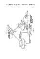
- FIG. 1is a geometric representation showing how a single point can be located in space
- FIG. 1Ais a matrix illustration, showing the roles of different components employable in the system of FIG. 1;
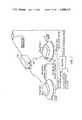
- FIG. 2is a diagrammatic illustration of a first embodiment of the invention
- FIG. 3is a view analogous to FIG. 2, but showing another embodiment
- FIG. 4is another diagrammatic view, showing a further embodiment
- FIG. 5is a further diagrammatic view of yet another embodiment of the invention.
- FIG. 6is a diagrammatic illustration of use of a frosted glass disk and a TV camera in lieu of discrete photo cells as in FIG. 3;
- FIG. 7is similar to FIG. 6, but the lens and frosted glass disk are replaced by allowing the projected patterns to impinge directly onto the TV sensor surface;
- FIG. 8is similar to FIG. 7, but the use of color is provided for;
- FIG. 9is similar to the method of FIG. 5, but uses 3-D shape in lieu of color;
- FIG. 10is a compromise between the method of FIG. 3, which uses three discreet photo detectors and the method of FIG. 7, which uses a TV camera.
- FIGS. 1 and 1Awill serve to provide a simple geometric description for locating a single point in space (the term "space” should be understood to refer to terrestrial as well as extraterrestrial space).
- the source of light required to make the system operativecan be resident either in the plane and/or line, or in the intersecting point itself.
- the possible roles of these three components of the systemare described by the matrix in FIG. 1A.
- Cis determined to lie on the intersection of two lines in space (rather than a line and a plane). This added dimension is redundant to the solution of the problem. Extending the configuration of FIG. 1 to three points in space requires only the means of handling multiple lines/planes emanating from the camera/projectors and means of properly corresponding particular lines and planes to particular points.
- FIG. 2shows an embodiment in which the light sources are located on the platform and cameras are located at positions off the platform.
- Three non-colinear sources 10are shown mounted to the platform 11.
- a point light sourceis approximated for each source 10 by grinding a spherical surface onto the end of a respective one of three thin fibre optic bundles 12.
- the latterserves to carry the light from the light generating source 13 which can be located conveniently elsewhere on the platform.
- the light generating source 13can be either a laser or a white light source.
- a means of providing a unique identity for each of three light sources 10is implemented by the three light modulators 15 shown between the light generating source 13 and the fibre optic bundles 12. Each of these modulators 15 is driven by a unique code generated by the encoder or code generator 16 which imparts an on-off modulation to each light source 10.
- Two TV-type cameras 17 and 18are located off-platform and are so situated that the three light points from sources 10 on the platform 11 are visible to both cameras 17, 18.
- the camera 17 to platform 11 to camera 18 angleshould be nominally 90° and never less than 30° or greater than 150°. Angles outside this range will cause severe geometric distortion of precision.
- Each camera 17, 18senses the images of three light sources 10.
- the image position on the TV fielduniquely determines each source 10 to be along a specific line in space.
- the identity of the particular source 10is determined by sensing and identifying the coded on-off light modulation associated with each source 10.
- the decoding processis done in the video processor 19, 20 associated with each TV camera 17, 18.
- the output of each video processor 19 or 20is digital data describing the identity of each light source 10 and its angular direction with respect to the center of the TV field of view.
- These signalsenter the computer 21 (known per se) which performs all position calculations and provides camera pointing control.
- the pointing angle of each camera 17, 18is servo-controlled to center the TV field of view about the platform 11.
- the TV optical magnificationcan be maximized, consistent with keeping all three light sources 10 within the field of view.
- the high optical magnificationoptimizes the angle determining precision of the system.
- the respective 2-axis TV pointing servo 22, 23is controlled from the computer 21 which has calculated platform position within the field of view. The servos 22, 23 are thus controlled to keep the three sources 10 centered within the field of view.
- Data resident in the computer 2 on a real time basisincludes the camera pointing angles (field of view centers) and the angular positions of each light source 10 with respect to these field of view centers.
- each light source 10is determined to be on a unique line in space emanating from each camera 17, 18.
- the computer 21calculates the interaction of these lines which determines the position of each light source 10 in space. Knowing the fixed mechanical position of the light sources 10 with respect to the platform 11 is then sufficient to enable the computer 21 to calculate and output the platform position and orientation in space.
- FIG. 3shows an embodiment in which light sensors are located on the platform and projectors at positions off the platform.
- the cameras of FIG. 2are here replaced by light projectors 30, 31 and the light sources by light sensors 32. These may be small “chips” which convert the projected light from projectors 30, 31 impinging on them to electrical signals. These are amplified and thresholded to provide digital signals to the computer 21, indicative of the presence or absence of projected light on the sensors 32. Thus, the computer 21 knows the instance in time when each sensor 32 is illuminated.
- the projectors 30, 31generate light beams in space whose angular position is appropriately modulated with time by commands from the computer 21. By correlating the detected time of sensor illumination with the projected beam position at that time, the computer 21 can thus determine the angular position of each sensor 32 with respect to each projector 30, 31.
- the angular position of the optical axis of each projector 30, 31is servo-controlled by commands from computer 21 to keep it centered on the platform. This optimizes the resolution and accuracy of the projected light patterns by minimizing the angular coverage required to illuminate all three light sensors 32. From FIG. 1 it is clear that one of the projectors 30, 31 need only project a plane in space while the other must project a line. Both the plane and line must be scanned in time so that each sensor 32 is illuminated somewhere during the scan.
- the plane projectorcan be implemented by optically generating a light plane, using cylindrical lenses 40 to collimate the rays from a light source.
- the thickness of a planewould be commensurate with the required resolution and the width sufficient to illuminate all sensors in one scan.
- a rotating mirror system 41will provide scanning orthogonal to the plane with the scan angle sufficient to illuminate all sensors.
- 2 orthogonal light planes scanned as abovecan effect the same result.
- first one planewould be turned on and scanned across the field once.
- a second orthogonal planewould be turned on and scanned once across the field orthogonal to the first. Alternating the scans between the two planes produces two illumination pulses on each sensor 32. These two time marks uniquely locate the sensor along a single line emanating from the projector.
- the scanning mechanism for all three light planescan be run continuously with the light planes sequentially turned on and off as orchestrated by the computer 21.
- the illumination pulses from each sensor 32can be attributed to a particular scanning plane.
- Alternative methods of implementing the plane/line projection patterninclude a raster scan with a pencil light beam to implement a line projection directly; (any of the methods common to projection TV systems and the like are appropriate for this implementation); scanning of a plane by using a sequence of coded multi-plane projections as known from the prior art; and orthogonal coded patterns of the general type mentioned in the preceding sentence effecting a line projection in a manner similar to scanned sentence effecting a line projection in a manner similar to scanned orthogonal planes.
- the computer processingmust include the associated decoding logarithms to appropriately determine the specific planes on which the sensor lies.
- a final embodimentinvolves the use of reflectors on the platform 11 and of one projector and one camera off the platform.
- Three non-colinear reflectors 50are shown mounted to the platform 11. These are physically small diffuse reflectors colored so as to reflect one of the three prime colors (i.e. one red, one green, and one blue). These reflectors are illuminated by an off-platform plane projector 51, similar to the scanning plane or a coded multi-plane projector implementation described with respect to FIG. 3. In this case, the spectral characteristics of the projected light must be nearly white to achieve proper reflection from the three reflectors 50.
- a color TV camera 52is mounted off platform to individually sense the reflected images of the three reflectors 50 and identify each reflector 50 by color.
- each reflector 50is identified and its position in space determined as the intersection of a line (defined by the camera image position) and a plane (defined by the plane projector). Both the projector 51 and camera 52 pointing positions 21 are servo-controlled (servos 22, 23) via the computer 21 to track the platform 11 as in FIGS. 1 and 2.
- FIG. 6shows a method of tracking the position and orientation of a platform similar to the method of FIG. 3 which uses three discrete photo cells.
- projectors 30 and 31project their patterns onto the etched glass disk 101. Either single planes and rays may be transmitted or multiple coded planes and rays may be transmitted by the projectors 30 and 31 onto the glass plate which is viewed by TV camera 100.
- Each point on the etched glass plate 101is measured by a discrete picture element of the TV camera.
- the etched glass plate and cameraare calibrated as in the prior art.
- Each point on the glass diskcan be treated as one of the discrete photo cells in the method of FIG. 3.
- FIG. 7shows a method similar to the method of FIG. 6, but the etched glass plate and camera lens have been eliminated. That platform or robot arm has thereby less bulk to carry. Several solid state TV cameras without a lens are available and are quite small. It is possible to separate the solid state TV chip 102 with a small amount of circuitry and mount it on the platform or robot arm and house the rest of the camera 108 elsewhere.
- FIG. 8shows the same method as FIG. 7 but with the addition of a color wheel 110 to allow simultaneous transmissions of projector codes (i.e., horizontal and vertical). If only one projector was to transmit in color, a better place to mount the color filter wheel would be on the platform of the projector and save bulk and weight on the measurement platform.
- projector codesi.e., horizontal and vertical
- FIG. 9shows a method of tracking the position and orientation of a platform or robot arm similar to the method of FIG. 5 which uses three discrete colored reflectors.
- This methodmeasures a known-shaped object 102 in the three dimensional method of the prior art or a two dimension and three dimensional method permitted by prior knowledge of the shape being measured.
- the advantage of this method over the method of FIG. 5is that more measurements are taken and thus statistical processing can be used for greater accuracy.
- a disadvantage of this method compared to the method of FIG. 5is that much more processing is required.
- Another advantage of this methodis that color is not required.
- Projector 106 and camera 107are mounted and calibrated on a platform. This platform combination comprises a three-dimensional sensor as already known in the art.
- FIG. 10is a compromise between the method of FIG. 3, which uses three discrete photo detectors, and the method of FIG. 7 which uses a TV camera.
- the main advantage of this systemis cost compared to a TV camera.
- the rotating detector 108cuts through the projected planes as in the methods of FIG. 3 and FIG. 7.
- the rotating detector 108has a photocell or fiber optic tip 110, which take the path 111 when shaft 112 rotates.
- the signs from element 110are transmitted from brushes 113; for example, which supply the signals to an amplifier in the well-known manner for use by a computer.
Landscapes
- Physics & Mathematics (AREA)
- Electromagnetism (AREA)
- Engineering & Computer Science (AREA)
- General Physics & Mathematics (AREA)
- Radar, Positioning & Navigation (AREA)
- Remote Sensing (AREA)
- Computer Networks & Wireless Communication (AREA)
- Length Measuring Devices By Optical Means (AREA)
Abstract
Description
Claims (5)
Priority Applications (1)
| Application Number | Priority Date | Filing Date | Title |
|---|---|---|---|
| US06/463,971US4488173A (en) | 1981-08-19 | 1983-02-04 | Method of sensing the position and orientation of elements in space |
Applications Claiming Priority (2)
| Application Number | Priority Date | Filing Date | Title |
|---|---|---|---|
| US06/294,341US4396945A (en) | 1981-08-19 | 1981-08-19 | Method of sensing the position and orientation of elements in space |
| US06/463,971US4488173A (en) | 1981-08-19 | 1983-02-04 | Method of sensing the position and orientation of elements in space |
Related Parent Applications (1)
| Application Number | Title | Priority Date | Filing Date |
|---|---|---|---|
| US06/294,341Continuation-In-PartUS4396945A (en) | 1981-08-19 | 1981-08-19 | Method of sensing the position and orientation of elements in space |
Publications (1)
| Publication Number | Publication Date |
|---|---|
| US4488173Atrue US4488173A (en) | 1984-12-11 |
Family
ID=26968474
Family Applications (1)
| Application Number | Title | Priority Date | Filing Date |
|---|---|---|---|
| US06/463,971Expired - LifetimeUS4488173A (en) | 1981-08-19 | 1983-02-04 | Method of sensing the position and orientation of elements in space |
Country Status (1)
| Country | Link |
|---|---|
| US (1) | US4488173A (en) |
Cited By (24)
| Publication number | Priority date | Publication date | Assignee | Title |
|---|---|---|---|---|
| US4686639A (en)* | 1985-02-07 | 1987-08-11 | Rockwell International Corporation | Free space microscope digitizing aid |
| US4703344A (en)* | 1985-03-30 | 1987-10-27 | Omron Tateisi Electronics Co. | Illumination system of the digital control type |
| US4791482A (en)* | 1987-02-06 | 1988-12-13 | Westinghouse Electric Corp. | Object locating system |
| US4828159A (en)* | 1988-02-22 | 1989-05-09 | The Boeing Company | Automatic flush head fastener inspection device |
| US4851905A (en)* | 1984-10-12 | 1989-07-25 | Diffracto Ltd. | Vision target fixture construction |
| US4873651A (en)* | 1987-04-21 | 1989-10-10 | Case Western Reserve University | Method and apparatus for reconstructing three-dimensional surfaces from two-dimensional images |
| US4942539A (en)* | 1988-12-21 | 1990-07-17 | Gmf Robotics Corporation | Method and system for automatically determining the position and orientation of an object in 3-D space |
| US5005147A (en)* | 1988-12-30 | 1991-04-02 | The United States Of America As Represented By The Administrator, The National Aeronautics And Space Administration | Method and apparatus for sensor fusion |
| US5319567A (en)* | 1992-11-23 | 1994-06-07 | Ford Motor Company | Non-contact method of obtaining dimensional information about a reference feature of an object |
| US5384717A (en)* | 1992-11-23 | 1995-01-24 | Ford Motor Company | Non-contact method of obtaining dimensional information about an object |
| US5394183A (en)* | 1992-05-05 | 1995-02-28 | Milliken Research Corporation | Method and apparatus for entering coordinates into a computer |
| US5414647A (en)* | 1992-11-23 | 1995-05-09 | Ford Motor Company | Non-contact method and system for building CAD models by integrating high density data scans |
| US5455765A (en)* | 1984-10-12 | 1995-10-03 | Sensor Adaptive Machines Inc. | Vision assisted fixture construction |
| US5638301A (en)* | 1994-06-02 | 1997-06-10 | Ford Motor Company | Method and system for inspecting die sets using free-form inspection techniques |
| US5729475A (en)* | 1995-12-27 | 1998-03-17 | Romanik, Jr.; Carl J. | Optical system for accurate monitoring of the position and orientation of an object |
| US5889550A (en)* | 1996-06-10 | 1999-03-30 | Adaptive Optics Associates, Inc. | Camera tracking system |
| US5901273A (en)* | 1995-10-17 | 1999-05-04 | Fuji Xerox Co., Ltd. | Two-dimensional position/orientation measuring mark, two-dimensional position/orientation measuring method and apparatus, control apparatus for image recording apparatus, and control apparatus for manipulator |
| US5936722A (en)* | 1996-08-15 | 1999-08-10 | Armstrong; Brian S. R. | Apparatus and method for determining the angular orientation of an object |
| US5974168A (en)* | 1998-04-16 | 1999-10-26 | International Business Machines Corporation | Acquiring bump maps from curved objects |
| US6384908B1 (en) | 1996-08-15 | 2002-05-07 | Go Sensors, Llc | Orientation dependent radiation source |
| US6496347B1 (en) | 2000-03-08 | 2002-12-17 | General Electric Company | System and method for optimization of a circuit breaker mechanism |
| US20060127852A1 (en)* | 2004-12-14 | 2006-06-15 | Huafeng Wen | Image based orthodontic treatment viewing system |
| US20060127836A1 (en)* | 2004-12-14 | 2006-06-15 | Huafeng Wen | Tooth movement tracking system |
| US20060127854A1 (en)* | 2004-12-14 | 2006-06-15 | Huafeng Wen | Image based dentition record digitization |
Citations (2)
| Publication number | Priority date | Publication date | Assignee | Title |
|---|---|---|---|---|
| US3793481A (en)* | 1972-11-20 | 1974-02-19 | Celesco Industries Inc | Range scoring system |
| US4396945A (en)* | 1981-08-19 | 1983-08-02 | Solid Photography Inc. | Method of sensing the position and orientation of elements in space |
- 1983
- 1983-02-04USUS06/463,971patent/US4488173A/ennot_activeExpired - Lifetime
Patent Citations (2)
| Publication number | Priority date | Publication date | Assignee | Title |
|---|---|---|---|---|
| US3793481A (en)* | 1972-11-20 | 1974-02-19 | Celesco Industries Inc | Range scoring system |
| US4396945A (en)* | 1981-08-19 | 1983-08-02 | Solid Photography Inc. | Method of sensing the position and orientation of elements in space |
Cited By (31)
| Publication number | Priority date | Publication date | Assignee | Title |
|---|---|---|---|---|
| US5455765A (en)* | 1984-10-12 | 1995-10-03 | Sensor Adaptive Machines Inc. | Vision assisted fixture construction |
| US5828566A (en)* | 1984-10-12 | 1998-10-27 | Sensor Adaptive Machines, Inc. | Vision assisted fixture construction |
| US5721677A (en)* | 1984-10-12 | 1998-02-24 | Sensor Adaptive Machines, Inc. | Vision assisted fixture construction |
| US4851905A (en)* | 1984-10-12 | 1989-07-25 | Diffracto Ltd. | Vision target fixture construction |
| US5696673A (en)* | 1984-10-12 | 1997-12-09 | Sensor Adaptive Machines Inc. | Vision assisted fixture construction |
| US5615108A (en)* | 1984-10-12 | 1997-03-25 | Sensor Adaptive Machines Inc. | Vision assisted fixture construction |
| US4686639A (en)* | 1985-02-07 | 1987-08-11 | Rockwell International Corporation | Free space microscope digitizing aid |
| US4703344A (en)* | 1985-03-30 | 1987-10-27 | Omron Tateisi Electronics Co. | Illumination system of the digital control type |
| US4791482A (en)* | 1987-02-06 | 1988-12-13 | Westinghouse Electric Corp. | Object locating system |
| US4873651A (en)* | 1987-04-21 | 1989-10-10 | Case Western Reserve University | Method and apparatus for reconstructing three-dimensional surfaces from two-dimensional images |
| US4828159A (en)* | 1988-02-22 | 1989-05-09 | The Boeing Company | Automatic flush head fastener inspection device |
| US4942539A (en)* | 1988-12-21 | 1990-07-17 | Gmf Robotics Corporation | Method and system for automatically determining the position and orientation of an object in 3-D space |
| US5005147A (en)* | 1988-12-30 | 1991-04-02 | The United States Of America As Represented By The Administrator, The National Aeronautics And Space Administration | Method and apparatus for sensor fusion |
| US5394183A (en)* | 1992-05-05 | 1995-02-28 | Milliken Research Corporation | Method and apparatus for entering coordinates into a computer |
| US5319567A (en)* | 1992-11-23 | 1994-06-07 | Ford Motor Company | Non-contact method of obtaining dimensional information about a reference feature of an object |
| US5414647A (en)* | 1992-11-23 | 1995-05-09 | Ford Motor Company | Non-contact method and system for building CAD models by integrating high density data scans |
| US5384717A (en)* | 1992-11-23 | 1995-01-24 | Ford Motor Company | Non-contact method of obtaining dimensional information about an object |
| US5638301A (en)* | 1994-06-02 | 1997-06-10 | Ford Motor Company | Method and system for inspecting die sets using free-form inspection techniques |
| US6115136A (en)* | 1995-10-17 | 2000-09-05 | Fuji Xerox Co., Ltd. | Two-dimensional position/orientation measuring mark, two-dimensional position/orientation measuring method and apparatus, control apparatus for image recording apparatus, and control apparatus for manipulator |
| US5901273A (en)* | 1995-10-17 | 1999-05-04 | Fuji Xerox Co., Ltd. | Two-dimensional position/orientation measuring mark, two-dimensional position/orientation measuring method and apparatus, control apparatus for image recording apparatus, and control apparatus for manipulator |
| US5884239A (en)* | 1995-12-27 | 1999-03-16 | Romanik, Jr.; Carl J. | Optical system for accurate monitoring of the position and orientation of an object |
| US5729475A (en)* | 1995-12-27 | 1998-03-17 | Romanik, Jr.; Carl J. | Optical system for accurate monitoring of the position and orientation of an object |
| US5889550A (en)* | 1996-06-10 | 1999-03-30 | Adaptive Optics Associates, Inc. | Camera tracking system |
| US5936722A (en)* | 1996-08-15 | 1999-08-10 | Armstrong; Brian S. R. | Apparatus and method for determining the angular orientation of an object |
| US6384908B1 (en) | 1996-08-15 | 2002-05-07 | Go Sensors, Llc | Orientation dependent radiation source |
| US5974168A (en)* | 1998-04-16 | 1999-10-26 | International Business Machines Corporation | Acquiring bump maps from curved objects |
| US6496347B1 (en) | 2000-03-08 | 2002-12-17 | General Electric Company | System and method for optimization of a circuit breaker mechanism |
| US20060127852A1 (en)* | 2004-12-14 | 2006-06-15 | Huafeng Wen | Image based orthodontic treatment viewing system |
| US20060127836A1 (en)* | 2004-12-14 | 2006-06-15 | Huafeng Wen | Tooth movement tracking system |
| US20060127854A1 (en)* | 2004-12-14 | 2006-06-15 | Huafeng Wen | Image based dentition record digitization |
| US20070141534A1 (en)* | 2004-12-14 | 2007-06-21 | Huafeng Wen | Image-based orthodontic treatment viewing system |
Similar Documents
| Publication | Publication Date | Title |
|---|---|---|
| US4396945A (en) | Method of sensing the position and orientation of elements in space | |
| US4488173A (en) | Method of sensing the position and orientation of elements in space | |
| US4146926A (en) | Process and apparatus for optically exploring the surface of a body | |
| US4687326A (en) | Integrated range and luminance camera | |
| EP0294101B1 (en) | System for measuring the angular displacement of an object | |
| US7903261B2 (en) | Controlling a projected pattern | |
| US9453913B2 (en) | Target apparatus for three-dimensional measurement system | |
| US5410410A (en) | Non-contact type measuring device for measuring three-dimensional shape using optical probe | |
| US4879664A (en) | Three-dimensional position sensor and three-dimensional position setting system | |
| US4775235A (en) | Optical spot scanning system for use in three-dimensional object inspection | |
| US20150022826A1 (en) | Target apparatus and method | |
| ATE519092T1 (en) | LASER-ASSISTED COORDINATE MEASURING APPARATUS AND LASER-ASSISTED COORDINATE MEASURING METHOD | |
| US5291264A (en) | Method and apparatus for the optical measurement of an angle between positions of components relative to each other | |
| US3726591A (en) | Stereoplotting apparatus for correlating image points disposed along epipolar lines | |
| US3806725A (en) | Apparatus for automatic tracking of pupil of eye | |
| US5052800A (en) | Boresighting method and apparatus | |
| CA1312755C (en) | Synchronous optical scanning apparatus | |
| US5410398A (en) | Automatic boresight compensation device | |
| WO1983004303A1 (en) | Apparatus for measuring the dimensions of cylindrical objects by means of a scanning laser beam | |
| US5767524A (en) | Optical device for determining the orientation of a solid body | |
| US4652749A (en) | Optical coordinate measuring system with dual path reflecting means | |
| US4179085A (en) | Optical boresight method for nutating system | |
| US4963984A (en) | Optical projection camera alignment system and method | |
| US4848903A (en) | Method and apparatus for measuring the optical axis of a guide beam projector | |
| US4411627A (en) | Articulated light guide |
Legal Events
| Date | Code | Title | Description |
|---|---|---|---|
| AS | Assignment | Owner name:ROBOTIC VISION SYSTEMS INC., 536 BROADHOLLOW ROAD, Free format text:ASSIGNMENT OF ASSIGNORS INTEREST.;ASSIGNORS:DI MATTEO, PAUL;RADEMACHER, PAUL;STERN, HOWARD;REEL/FRAME:004144/0447 Effective date:19830107 | |
| STCF | Information on status: patent grant | Free format text:PATENTED CASE | |
| FPAY | Fee payment | Year of fee payment:4 | |
| REMI | Maintenance fee reminder mailed | ||
| FEPP | Fee payment procedure | Free format text:PAYOR NUMBER ASSIGNED (ORIGINAL EVENT CODE: ASPN); ENTITY STATUS OF PATENT OWNER: SMALL ENTITY | |
| FPAY | Fee payment | Year of fee payment:8 | |
| SULP | Surcharge for late payment | ||
| FPAY | Fee payment | Year of fee payment:12 | |
| AS | Assignment | Owner name:BANK OF NEW YORK, THE, NEW YORK Free format text:GRANT OF SECURITY INTEREST (PATENTS);ASSIGNOR:ROBOTIC VISION SYSTEMS, INC.;REEL/FRAME:009114/0385 Effective date:19980318 | |
| AS | Assignment | Owner name:ROBOTIC VISION SYSTEMS, INC., NEW YORK Free format text:RELEASE OF SECURITY INTEREST;ASSIGNOR:THE BANK OF NEW YORK;REEL/FRAME:010731/0869 Effective date:20000329 | |
| AS | Assignment | Owner name:PNC BANK, NATIONAL ASSOCIATION, NEW JERSEY Free format text:SECURITY INTEREST;ASSIGNOR:ROBOTIC VISION SYSTEMS, INC.;REEL/FRAME:010804/0380 Effective date:20000428 |