US4486901A - Multi-layered, open-celled foam shock absorbing structure for athletic equipment - Google Patents
Multi-layered, open-celled foam shock absorbing structure for athletic equipmentDownload PDFInfo
- Publication number
- US4486901A US4486901AUS06/478,681US47868183AUS4486901AUS 4486901 AUS4486901 AUS 4486901AUS 47868183 AUS47868183 AUS 47868183AUS 4486901 AUS4486901 AUS 4486901A
- Authority
- US
- United States
- Prior art keywords
- foam
- shock absorbing
- absorbing structure
- faces
- open
- Prior art date
- Legal status (The legal status is an assumption and is not a legal conclusion. Google has not performed a legal analysis and makes no representation as to the accuracy of the status listed.)
- Expired - Fee Related
Links
Images


Classifications
- A—HUMAN NECESSITIES
- A41—WEARING APPAREL
- A41D—OUTERWEAR; PROTECTIVE GARMENTS; ACCESSORIES
- A41D13/00—Professional, industrial or sporting protective garments, e.g. surgeons' gowns or garments protecting against blows or punches
- A41D13/015—Professional, industrial or sporting protective garments, e.g. surgeons' gowns or garments protecting against blows or punches with shock-absorbing means
- A41D13/0153—Professional, industrial or sporting protective garments, e.g. surgeons' gowns or garments protecting against blows or punches with shock-absorbing means having hinged or separable parts
- A—HUMAN NECESSITIES
- A41—WEARING APPAREL
- A41D—OUTERWEAR; PROTECTIVE GARMENTS; ACCESSORIES
- A41D13/00—Professional, industrial or sporting protective garments, e.g. surgeons' gowns or garments protecting against blows or punches
- A41D13/05—Professional, industrial or sporting protective garments, e.g. surgeons' gowns or garments protecting against blows or punches protecting only a particular body part
- A41D13/055—Protector fastening, e.g. on the human body
- A41D13/0581—Protector fastening, e.g. on the human body with permanent fastening means
- A41D13/0587—Integral with the garment
- A—HUMAN NECESSITIES
- A63—SPORTS; GAMES; AMUSEMENTS
- A63B—APPARATUS FOR PHYSICAL TRAINING, GYMNASTICS, SWIMMING, CLIMBING, OR FENCING; BALL GAMES; TRAINING EQUIPMENT
- A63B71/00—Games or sports accessories not covered in groups A63B1/00 - A63B69/00
- A63B71/08—Body-protectors for players or sportsmen, i.e. body-protecting accessories affording protection of body parts against blows or collisions
- A63B71/12—Body-protectors for players or sportsmen, i.e. body-protecting accessories affording protection of body parts against blows or collisions for the body or the legs, e.g. for the shoulders
- A—HUMAN NECESSITIES
- A41—WEARING APPAREL
- A41D—OUTERWEAR; PROTECTIVE GARMENTS; ACCESSORIES
- A41D13/00—Professional, industrial or sporting protective garments, e.g. surgeons' gowns or garments protecting against blows or punches
- A41D13/05—Professional, industrial or sporting protective garments, e.g. surgeons' gowns or garments protecting against blows or punches protecting only a particular body part
- A41D13/055—Protector fastening, e.g. on the human body
- A41D13/0581—Protector fastening, e.g. on the human body with permanent fastening means
- A41D13/0593—Protector fastening, e.g. on the human body with permanent fastening means in a sealed pocket
- A—HUMAN NECESSITIES
- A63—SPORTS; GAMES; AMUSEMENTS
- A63B—APPARATUS FOR PHYSICAL TRAINING, GYMNASTICS, SWIMMING, CLIMBING, OR FENCING; BALL GAMES; TRAINING EQUIPMENT
- A63B71/00—Games or sports accessories not covered in groups A63B1/00 - A63B69/00
- A63B71/08—Body-protectors for players or sportsmen, i.e. body-protecting accessories affording protection of body parts against blows or collisions
- A63B71/12—Body-protectors for players or sportsmen, i.e. body-protecting accessories affording protection of body parts against blows or collisions for the body or the legs, e.g. for the shoulders
- A63B71/1225—Body-protectors for players or sportsmen, i.e. body-protecting accessories affording protection of body parts against blows or collisions for the body or the legs, e.g. for the shoulders for the legs, e.g. thighs, knees, ankles, feet
- A63B2071/1241—Body-protectors for players or sportsmen, i.e. body-protecting accessories affording protection of body parts against blows or collisions for the body or the legs, e.g. for the shoulders for the legs, e.g. thighs, knees, ankles, feet for the thigh
- Y—GENERAL TAGGING OF NEW TECHNOLOGICAL DEVELOPMENTS; GENERAL TAGGING OF CROSS-SECTIONAL TECHNOLOGIES SPANNING OVER SEVERAL SECTIONS OF THE IPC; TECHNICAL SUBJECTS COVERED BY FORMER USPC CROSS-REFERENCE ART COLLECTIONS [XRACs] AND DIGESTS
- Y10—TECHNICAL SUBJECTS COVERED BY FORMER USPC
- Y10S—TECHNICAL SUBJECTS COVERED BY FORMER USPC CROSS-REFERENCE ART COLLECTIONS [XRACs] AND DIGESTS
- Y10S2/00—Apparel
- Y10S2/908—Guard or protector having a hook-loop type fastener
- Y10S2/91—Hand or wrist protector
Definitions
- This inventionrelates to shock absorbing equipment, and more particularly to protective shock absorbing athletic equipment for wear during contact sports, and to methods for making such equipment.
- Shock absorbing equipmenthas long been known and used where shock attenuation is required.
- closed-cell foam materialshave been used in automobile dash boards
- sand-filled barrelshave been deployed about highway obstructions
- air-bags that inflate upon vehicle impacthave been used in passenger compartments.
- Raw cotton and wool battinghave been used for padding and packaging needs
- both batting and inflatable membershave been used in clothing and athletic equipment.
- One type of known prior art athletic equipmentincludes a relatively hard outer shell of leather, vulcanized fiber, or similar material, and an inner layer of soft padding material. So constructed, the hard outer layer receives the applied force or shock and serves to spread the force over a large area where it is absorbed and cushioned by the soft padding material.
- Known prior art padding materialsinclude cotton padding, foam rubber, foam plastic material, sponge rubber, expanded rubber or vinyl and the like, with the resilience of such material tending to absorb a portion of the applied force.
- Another known type of athletic equipmentincludes an inflatable balloon-like structure which is inflated with air to a pressure above one atmosphere and then sealed to maintain the air within the structure.
- a forceis imparted to such a structure, a portion of the air volume within the structure immediately adjacent the point of contact on the structure is forced to another region within the structure causing the entire structure to balloon.
- This ballooning effecttends to redistribute the applied force in the same manner that stepping on one end of an elongated balloon redistributes the applied force to the other end of the balloon causing the other end to bulge.
- the known prior art shock absorbing equipmentdoes not effectively reduce the force actually imparted to the user to a negligible value.
- shock absorbing structure for athletic equipmentis provided for controlled shock attenuation. While the present invention has many applications, it will generally be described with reference to athletic equipment. It will be apparent to those skilled in the art that the present teachings may advantageously be employed in other applications where controlled shock attenuation is required.
- the present inventionutilizes a controlled transfer of air between an interior region and the atmosphere outside the piece of shock absorbing equipment to present the force inflicted upon the equipment with an oppositely directed force of substantially equal magnitude to impart to the wearer a substantially negligible resultant force.
- a flexible open-celled foam portionis covered with a fabric.
- the fabricis generally air impermeable, but has a plurality of air permeable regions selectively distributed.
- the air permeable regionsproduce continuous fluid communication between the foam portion inside the fabric covering and the atmosphere outside.
- a portion of the volume of air contained within the cell structure of the foamis selectively transferred through the air permeable regions of the fabric covering to the outside of the covering.
- the rate of transferis controlled such that the inflicted force is met with a resistance of substantially equal magnitude and opposite direction to produce a resultant force of substantially negligible magnitude for infliction upon the wearer.
- Shield structureis included to distribute the force across the fabric covered foam.
- the flexible open-celled foam portionincludes a multi-layered laminate of open-celled foams having different foam densities.
- the laminateincludes at least three foam layers.
- the laminateincludes a plurality of foam layers disposed adjacent an inflatable-deflatable structural element.
- a method for making shock absorbing structure for athletic equipmentincludes cutting open-celled foam into a desired pattern, bonding an air-tight fabric to the foam to form an air-tight enclosure about the foam, and inflicting a plurality of holes in the fabric at predetermined locations such that the holes penetrate through the fabric and into the cell structure of the foam.
- FIG. 1is a perspective view of football shoulder pads, a rib protector, hip pads and thigh pads in accordance with the present invention
- FIG. 2is a perspective view of a portion of the shoulder pads illustrated in FIG. 1;
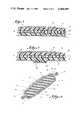
- FIG. 3is a section view through the shoulder pad illustrated in FIG. 2 along the line 3--3, with the structure layed substantially flat;
- FIG. 4is an alternate embodiment of the structure illustrated in FIG. 3;
- FIG. 5is a schematic cross-section view of shock absorbing structure according to the present invention.
- FIGS. 6a-6hare schematic illustrations of the effects of a force F 1 upon shock absorbing structure according to the present invention.
- protective athletic equipment having shock absorbing structureinclude shoulder pads 2, a rib protector 4, hip pads 6, and thigh pads 8.
- Each piece of equipmentincludes a fabric covered foam portion (2a, 4a, 6a, 8a) disposed against the body of the wearer, and a shield structure (2b, 4b, 6b, 8b) to distribute an applied force across at least a portion of the fabric covered foam portion.
- the shoulder pads 2, the rib protector 4, the hip pads 6 and the thigh pads 8each have essentially the same shock absorbing structure in accordance with the present invention, and each are constructed in essentially the same manner. Therefore, for sake of brevity, only the shoulder pads 2 will be described in detail.
- the shoulder pads illustrated in FIG. 1include numerous shield structures and fabric covered foam portions.
- a pair of shoulder pads 2having only a fabric covered foam portion 2a and a shield structure 2b collectively referred to herein as the shock absorbing structure 10.
- Such a pair of shoulder padsis illustrated in FIG. 2 in perspective view and in FIG. 3 in cross section view along the line 3--3 of FIG. 2.
- the shock absorbing structure 10has been unfolded from its position about the shoulder of the wearer and layed substantially flat.
- FIG. 5illustrates schematically in cross section the shock absorbing structure 10 according to the present invention.
- the shock absorbing structure 10includes first and second pieces of fabric 12 and 14 disposed about a foam portion 16.
- the fabricis a nylon material that is rendered relatively air-tight by the inclusion of a polyurethane coating on the face of the fabric disposed adjacent the foam portion 16.
- the fabric pieces 12 and 14are bonded to each other along an edge 18 to form an air-tight enclosure about the foam portion 16.
- a plurality of apertures 22are included in the fabric pieces 12 and 14 along the edge 18.
- the apertures 22penetrate through the fabric causing the interior of the fabric enclosure housing the foam portion 16 to be in continuous fluid communication with the atmosphere outside the structure 10.
- a binding tape 24is placed about the edge 18 and sewn in place. Attachment of the tape 24 increases the mechanical strength of the edge 18 and enhances the appearance of the structure 10.
- One or more shield elements 26 of a semi-rigid plastic or other suitable materialmay be affixed by suitable means to the structure 10 to distribute a force inflicted on the structure 10 over a large surface area of the fabric enclosed foam portion.
- the shield element 26is removably connected to the thigh pad 8 by releasable mating hook and loop fastening structure 28, for example, the hook and loop structure sold under the name VELCRO.
- the shield element 26is attached to the fabric enclosed foam portion by rivets.
- the plastic material of the shield element 26, for example the shield structure 8b illustrated in FIG. 1,is cut into a desired pattern and then shaped by heating or any other suitable process so that when attached to the fabric covered foam portion 8a of the thigh pad 8, the resulting thigh pad 8 has a desired contour adapted to engage the thigh of the wearer.
- the shield element 26may have a layer of open-celled material, such as polyolefin foam, bonded to its outer surface.
- a foam layer(not illustrated) tends to reduce the likelihood of injury to opponent players who inflict a force upon the shield element 26.
- the foam layertends to facilitate distributing the inflicted force over a relatively large surface area of the shock absorbing structure 10.
- the thickness of the foam layeris approximately one-half to twice that of the shield element 26.
- the foam portion 16includes a first face 32, a second face 34, and a peripheral edge 36.
- the fabric pieces 12, 14include coated faces 38, 40 defining a cavity 42 and uncoated faces 44, 46 in communication with the atmosphere outside the shock absorbing structure 10.
- the first and second faces 32 and 34 of the foam portion 16are bonded to the coated fabric faces 38 and 40, respectively, to form a laminate which permits adjacent fabric/foam faces to move as a unit.
- the fabric piecesmay be bonded to the foam portion by adheringly applying the fabric pieces to the foam portion, such as by heat sealing.
- the fabricmay be coated if desired and then bonded to the foam portion in any suitable mannner, such that the enclosure or cavity 42 formed by the fabric is substantially air-tight and the faces of the foam portion are bonded, at least in part, to the inside surface of the cavity.
- any suitable method of bonding pieces of relatively air-tight fabric to foammay be employed, such as the use of radio frequency induction heating techniques, the use of adhesive materials, and so forth.
- pieces of fabric that are not relatively air-tightmay be bonded to the foam portion such that a substantially air-tight enclosure is formed.
- the peripheral edge 36 of the foam portion 16may also be bonded to the faces 38 and 40 of the fabric pieces 12 and 14. While such bonding is not necessary, it further enhances control over the transfer of air between the cellular structure of the foam portion inside the enclosure and the atmosphere outside the enclosure.
- the foam portion 16is an open-celled material such as polyurethane foam. It may be a reticulated foam, that is, a foam which has been fire polished to destroy the membranes or thin films joining the strands which divide continguous cells without destroying the strands of the skeletal structure or which has been treated chemically to destroy the strands, or any other suitable material having an open-celled structure.
- the cellular structure of the foam portion 16, which is in fluid communication with the atmosphere outside of the enclosure or cavity 42 by way of the apertures 22,constitutes a reservoir inside the cavity which releasably holds air.
- the foam portion 16is illustrated in greater detail.
- the foam portion 16is a multi-layered laminate having foam layers 16a, 16b and 16c. As illustrated, the foam layer 16a is disposed adjacent the first piece of fabric 12, the foam layer 16c is disposed adjacent the second piece of fabric 14, and the foam layer 16b is disposed between the foam layers 16a and 16c.
- Each foam layer 16a, 16b and 16chave a different foam density.
- the density of the foam layer 16cwhich is designed to be disposed adjacent the body of the wearer, has the lowest foam density. Its foam density should be no more than approximately one pound per cubic foot. The preferred range of densities is between one-half and three-quarter pound per cubic foot.
- Soft foamis used in foam layer 16c to enhance comfort levels and provide proper fit. Since the structure 10 must be shaped to conform to the body of the wearer, the foam layer 16c must have sufficient softness to conform to the contour of the body while providing good body contact.
- an alternate embodiment illustrated in FIG. 4includes a foam layer 16c having a plurality of regions 16d of varied height.
- a foam layer 16chaving a plurality of regions 16d of varied height.
- sides 16e of the height-varied regions 16dmove closer together and tend to form a firmer fit than the structure illustrated in FIG. 3.
- the outer foam layer 16ahas a relatively high foam density.
- the density rangeis from approximately 3 pounds per cubic foot to 16 pounds per cubic foot or more.
- the preferred rangeis approximately 3 to 4 pounds per cubic foot.
- the foam layer 16b sandwiched between the high density outer foam layers 16a and the low density inner foam layer 16chas an intermediate density between the densities of the inner and outer foam layers.
- the preferred density of the foam layer 16bis approximately 2 pounds per cubic foot.
- the foam portion 16 in the illustrated embodimenthas three foam densities by virtue of having three foam members, 16a, 16b and 16c. More than three foam members may be used. It is important that the foam layer closest the body have a low enough density for enhanced comfort and fit, and the density of the layer furthest from the body be sufficiently great so that the shock absorbing structure 10 adequately absorbs the inflicted force.
- an inflatable-deflatable structural elementis used in place of either foam layer 16a or foam layer 16c.
- the foam portion 16 in these alternate embodimentsis a multi-layered laminate of a plurality of open-celled foams having different foam densities, and the inflatable-deflatable structural element is disposed adjacent the multi-layered foam laminate.
- the inflatable-deflatable structural elementincludes an inflatable-deflatable chamber, and may include open-celled foam disposed within the chamber.
- a schematically illustrated shock absorbing structure 10 disposed adjacent a wearer 52includes an air-tight fabric enclosure 54 having a cavity 56.
- Flexible open-celled foam portion 58is disposed within the cavity 56 such that the outer surface of the foam portion is bonded to the inner surface of the cavity.
- a plurality of apertures 60are included in the air-tight fabric enclosure 54 and provide continuous fluid communication between the cavity 56 and the atmosphere outside the shock absorbing structure 10.
- the cells of the foam portion 58 in the cavity 56contain a first volume of air at one atmosphere of pressure.
- the pressure within and without the shock absorbing structure 10is the same because apertures 60 reduce the pressure differential across the portion of the fabric enclosure 54 containing the air-permeable apertures 60 to a quiescent value of zero. Since the inflicted external force is zero, the resulted force R transmitted to the wearer 52 is also zero.
- a force F 1is inflicted upon the shock absorbing structure 10.
- the inflicted forcemay tend to distort the shape of the cavity 56, but it cannot alter the volume of air contained within the cavity 56 because air is essentially an incompressible fluid.
- the apertures 60were uncontrollably large, the inflicted force F 1 would tend to collapse the structure 10 expelling the air contained within the cellular structure of the foam portion 58 through the aperture 60. In either case, a significant portion of the inflicted force would likely be imparted to the wearer. Controlled expulsion of the air contained in the cellular structure, however, reduces the resultant force imparted to the wearer to substantially zero.
- the force F 1exists for some finite period of time and thus can be viewed as increasing in magnitude from zero to some maximum value, dwelling at that maximum value for some finite period of time, and then decreasing from that maximum value to zero.
- FIGS. 6b, 6c and 6dschematically illustrate the behavior of the shock absorbing structure 10 as the inflicted force increases to its maximum value.
- the pressure within the cavity 56increases to a value above one atmosphere and air within the cellular structure of the foam portion 58 is expelled through the apertures 60. Both the air pressure in the cavity and the volume of the cavity decrease.
- the inflicted force F 1then decreases in magnitude from the maximum value to zero, and the elasticity of the foam portion 58 causes the cavity 56 to increase in volume.
- airis drawn through the apertures 60 and into the cavity 56 from the atmosphere outside the shock absorbing structure 10. This is schematically illustrated in FIGS. 6f and 6g.
- the rate at which air is drawn into the cavity 56 and thus the rate at which the volume of the cavity increases,is again determined by the number and size of the apertures 60 and is chosen such that the forces F 1 and F 2 add vectorially to produce a resultant force R of substantially zero magnitude.
- FIG. 6hdepicts a condition identical to that of FIG. 6a.
- the pressure within and without the cavity 56is at one atmosphere.
- shock absorbing structure 10is made by bonding together a plurality of open-celled foam layers having different foam densities to form a laminate, and cutting the laminate to a desired pattern.
- a plurality of foam layersmay each be cut to a desired pattern, and then the cut members bonded together to form a laminate.
- the laminated foam memberhas first and second faces and a peripheral edge.
- a piece of air-tight fabricis bonded to each face of the foam member, and then the two pieces of fabric are bonded to each other adjacent the peripheral edge of the foam member.
- a plurality of holesare then inflicted into the fabric adjacent the peripheral edge of the foam member.
- the holespenetrate through the fabric and through the peripheral edge of the foam member to provide continuous fluid communication between the open-celled structure of the foam and the atmosphere outside the shock absorbing structure 10.
- the holesare dimensioned and spaced one from the other to give the shock absorbing structure 10 a predetermined responsiveness to a given inflicted force.
- the two pieces of air-tight fabricmay be bonded to each other such that the inner face of one is bonded to the outer face of the other.
- the two pieces of fabricIn other shock absorbing structures, such as thigh pads, the two pieces of fabric have their inner faces bonded to one another, thereby forming the edge 18 best illustrated in FIG. 5. When such an edge is formed, the edge is trimmed and a binding tape 24 placed about the edge and sewn in place.
- the shield element 26is then cut and formed to the desired shape, and attached to the fabric covered foam member.
- the shield memberis releasably attached using hook and loop fastening structure, or any other suitable releasable structure. It may, however, be fixedly attached by sewing, riveting, or in any other suitable manner.
- the inflatable-deflatable structural elementmay be similar to those described in U.S. Pat. Nos. 3,675,377 and 3,866,241, which are hereby incorporated by reference.
- the air permeable regions selectively distributed in the generally air impermeable fabric for controlled continuous fluid communication between the foam portion enclosed by the fabric and the atmosphere outsideneed not be apertures. Any suitable structure may be used which provides such controlled continuous fluid communication. For example, one or more discrete valve members may be used. Valve members which permit fluid flow in only one direction may also be used, provided the unidirectional valve members are disposed such that at least one permits air to flow into the enclosure and at least one permits air to flow out of the enclosure.
- the shield elementsneed not be made of semi-rigid plastic. Any suitable structure which distributes the inflicted force over a relatively large surface area may be used. Additionally, shield elements may be included within the fabric enclosed foam laminate.
Landscapes
- Health & Medical Sciences (AREA)
- General Health & Medical Sciences (AREA)
- Physical Education & Sports Medicine (AREA)
- Engineering & Computer Science (AREA)
- Textile Engineering (AREA)
- Professional, Industrial, Or Sporting Protective Garments (AREA)
Abstract
Description
Claims (9)
Priority Applications (3)
| Application Number | Priority Date | Filing Date | Title |
|---|---|---|---|
| US06/478,681US4486901A (en) | 1982-03-12 | 1983-03-25 | Multi-layered, open-celled foam shock absorbing structure for athletic equipment |
| US06/495,753US4513449A (en) | 1983-03-25 | 1983-05-18 | Shock absorbing athletic equipment |
| US06/512,238US4441211A (en) | 1983-03-25 | 1983-07-11 | Protective batting jacket |
Applications Claiming Priority (2)
| Application Number | Priority Date | Filing Date | Title |
|---|---|---|---|
| US35758882A | 1982-03-12 | 1982-03-12 | |
| US06/478,681US4486901A (en) | 1982-03-12 | 1983-03-25 | Multi-layered, open-celled foam shock absorbing structure for athletic equipment |
Related Parent Applications (1)
| Application Number | Title | Priority Date | Filing Date |
|---|---|---|---|
| US35758882AContinuation-In-Part | 1982-03-12 | 1982-03-12 |
Related Child Applications (2)
| Application Number | Title | Priority Date | Filing Date |
|---|---|---|---|
| US06/495,753Continuation-In-PartUS4513449A (en) | 1983-03-25 | 1983-05-18 | Shock absorbing athletic equipment |
| US06/512,238Continuation-In-PartUS4441211A (en) | 1983-03-25 | 1983-07-11 | Protective batting jacket |
Publications (1)
| Publication Number | Publication Date |
|---|---|
| US4486901Atrue US4486901A (en) | 1984-12-11 |
Family
ID=26999715
Family Applications (1)
| Application Number | Title | Priority Date | Filing Date |
|---|---|---|---|
| US06/478,681Expired - Fee RelatedUS4486901A (en) | 1982-03-12 | 1983-03-25 | Multi-layered, open-celled foam shock absorbing structure for athletic equipment |
Country Status (1)
| Country | Link |
|---|---|
| US (1) | US4486901A (en) |
Cited By (68)
| Publication number | Priority date | Publication date | Assignee | Title |
|---|---|---|---|---|
| GB2177892A (en)* | 1985-07-23 | 1987-02-04 | Stafford Rubber Co Ltd | Guards for games players |
| US4700403A (en)* | 1982-08-17 | 1987-10-20 | Sports Marketing, Inc. | Protective cushion |
| US4723322A (en)* | 1987-03-16 | 1988-02-09 | Spenco Medical Corporation | Knee pad |
| US4872216A (en)* | 1988-05-13 | 1989-10-10 | Riddell, Inc. | Cantilever strap for football shoulder pads |
| US4926503A (en)* | 1988-05-13 | 1990-05-22 | Riddell, Inc. | Athletic shock absorbing pad |
| USD309805S (en) | 1987-03-16 | 1990-08-07 | Kimberly-Clark Corporation | Aerobic knee pad |
| US4985931A (en)* | 1989-10-17 | 1991-01-22 | Riddell, Inc. | Shock absorbing pad structure for athletic equipment |
| US4991230A (en)* | 1989-08-25 | 1991-02-12 | Vacanti Eugene J | Shock absorbing body protective pads |
| US5235715A (en)* | 1987-09-21 | 1993-08-17 | Donzis Byron A | Impact asborbing composites and their production |
| US5398342A (en)* | 1992-05-06 | 1995-03-21 | Easton Sports | Air management baseball glove |
| EP0714613A2 (en) | 1994-11-28 | 1996-06-05 | Marion Franklin Rudy | Article of footwear having multiple fluid containing members |
| US5530966A (en)* | 1992-12-21 | 1996-07-02 | West; Joseph H. | Protective garment for baseball umpires having an inner cushioned layer and an outer layer of interconnected plates |
| US5701611A (en)* | 1995-12-05 | 1997-12-30 | Ed Tobergte Associates, Inc. | Protective pad construction |
| US5881395A (en)* | 1993-07-08 | 1999-03-16 | Donzis; Byron A | Impact absorbing pad |
| US5918310A (en)* | 1997-05-09 | 1999-07-06 | Farahany; Amir H. | Body protective garment |
| WO1999040979A1 (en)* | 1998-02-13 | 1999-08-19 | Patrick Antony Hayes | Sports guards |
| US5993585A (en)* | 1998-01-09 | 1999-11-30 | Nike, Inc. | Resilient bladder for use in footwear and method of making the bladder |
| WO1999060895A1 (en)* | 1998-05-27 | 1999-12-02 | Switlik Parachute Co., Inc. | Method and apparatus for making self-inflatable mattresses and cushions |
| US6070273A (en)* | 1998-03-27 | 2000-06-06 | Sgro; Joseph | Body pads particulary for sports |
| US6122785A (en)* | 1997-07-01 | 2000-09-26 | Airsports Technology, L.L.C. | Air pad |
| US6128779A (en)* | 1997-11-14 | 2000-10-10 | Jas D. Easton, Inc. | Limb protector |
| US6170177B1 (en) | 1998-09-28 | 2001-01-09 | John P. Frappier | Footwear customization system and process |
| US6195809B1 (en)* | 1999-12-13 | 2001-03-06 | Prevent Products, Inc. | Hip-pad for protection of greater trochanter |
| US6425195B1 (en) | 1987-09-21 | 2002-07-30 | Byron A. Donzis | Impact absorbing composites and their production |
| US6449878B1 (en) | 2000-03-10 | 2002-09-17 | Robert M. Lyden | Article of footwear having a spring element and selectively removable components |
| US6490730B1 (en) | 1989-09-20 | 2002-12-10 | Robert M. Lyden | Shin-guard, helmet, and articles of protective equipment including light cure material |
| US6519780B2 (en)* | 2001-04-04 | 2003-02-18 | Edward L. Goodwin | Air-holding protective foam pad construction |
| RU2201703C2 (en)* | 2001-05-23 | 2003-04-10 | Санкт-Петербургский государственный университет технологии и дизайна | Multilayer packet |
| US6601042B1 (en) | 2000-03-10 | 2003-07-29 | Robert M. Lyden | Customized article of footwear and method of conducting retail and internet business |
| US6681403B2 (en) | 2000-03-13 | 2004-01-27 | Robert M. Lyden | Shin-guard, helmet, and articles of protective equipment including light cure material |
| US6704943B2 (en)* | 2001-12-31 | 2004-03-16 | Kisiel Technologies, S.L. | Inner cushions for helmets |
| US20040061299A1 (en)* | 2002-10-01 | 2004-04-01 | Garner Philippa V. | Scooter stabilizing systems and methods |
| US20040078873A1 (en)* | 2002-10-18 | 2004-04-29 | The Hipsaver Co., Inc. | Washable protective pad |
| US20040128748A1 (en)* | 2003-01-03 | 2004-07-08 | Monica Mark D. | Protective pad apparatus having air ventilating and restrictive radiant heat transfer/absorption aspects |
| US6796056B2 (en) | 2002-05-09 | 2004-09-28 | Nike, Inc. | Footwear sole component with a single sealed chamber |
| US20040237346A1 (en)* | 2003-05-28 | 2004-12-02 | Rudy Marion Franklin | Self-inflating cushion and footwear including same |
| US6842915B2 (en)* | 2001-12-20 | 2005-01-18 | Nike, Inc. | Device and method for securing apparel to protective equipment |
| US20050086728A1 (en)* | 2003-10-23 | 2005-04-28 | Tobergte Edward H. | Football shoulder pads |
| US20060021251A1 (en)* | 2002-05-09 | 2006-02-02 | Nike, Inc. | Footwear sole component with an insert |
| US20060053535A1 (en)* | 2004-09-13 | 2006-03-16 | Ide Thad M | Shoulder pad for contact sports |
| US7016867B2 (en) | 2000-03-10 | 2006-03-21 | Lyden Robert M | Method of conducting business including making and selling a custom article of footwear |
| US20060179545A1 (en)* | 2005-02-17 | 2006-08-17 | Arveda, Llc D/B/A Stromgren Supports, Inc. | Athletic protective padding |
| US7107235B2 (en) | 2000-03-10 | 2006-09-12 | Lyden Robert M | Method of conducting business including making and selling a custom article of footwear |
| US20080222766A1 (en)* | 2005-02-17 | 2008-09-18 | Arensdorf Stephen C | Athletic protective padding |
| US20090276932A1 (en)* | 2008-05-08 | 2009-11-12 | Gregory May | Shock absorber for a forearm protecting device |
| US7752775B2 (en) | 2000-03-10 | 2010-07-13 | Lyden Robert M | Footwear with removable lasting board and cleats |
| US20100192287A1 (en)* | 2004-09-13 | 2010-08-05 | Nelson Kraemer | Shoulder pads |
| US20100281606A1 (en)* | 2008-10-31 | 2010-11-11 | Kordecki Michael E | Protective Shoulder Pads with Release Mechanism |
| US7979918B2 (en) | 2008-02-14 | 2011-07-19 | Warrior Sports, Inc. | Protective covering |
| US20120246788A1 (en)* | 2011-03-28 | 2012-10-04 | Harrell Jeremy L | Multipurpose Cooling and Trauma Attenuating Devices and Associated Methods |
| US20130000024A1 (en)* | 2011-06-30 | 2013-01-03 | David Perreault | Reversible baseball or softball chest protector |
| USD674576S1 (en) | 2011-05-18 | 2013-01-22 | L.H. Holdings, Inc. | Padded sports garment |
| US20130312152A1 (en)* | 2012-05-23 | 2013-11-28 | Warrior Sports, Inc. | Two-way protective pad construction |
| WO2014143832A1 (en)* | 2013-03-15 | 2014-09-18 | Russell Brands, Llc | Foam beads for padding and body protection |
| US8850613B2 (en) | 2009-01-06 | 2014-10-07 | Riddell, Inc. | Protective contact sports pads with release mechanism |
| USD731122S1 (en) | 2013-01-14 | 2015-06-02 | Jeremy L. Harrell | Inflatable pad |
| USD738577S1 (en) | 2013-01-14 | 2015-09-08 | Jeremy L. Harrell | Inflatable pad pattern |
| USD738576S1 (en) | 2013-01-14 | 2015-09-08 | Jeremy L. Harrell | Inflatable pad pattern |
| WO2015153343A1 (en)* | 2014-03-14 | 2015-10-08 | Russell Brands, Llc | Protective foam material and pads |
| US9174111B2 (en) | 2012-07-06 | 2015-11-03 | Warrior Sports, Inc. | Protective athletic equipment |
| USD743633S1 (en) | 2013-01-14 | 2015-11-17 | Jeremy L. Harrell | Inflatable pad pattern |
| US20160235134A1 (en)* | 2015-02-13 | 2016-08-18 | Enma TROUTNER | Therapeutic cushioning pants |
| US20180085655A1 (en)* | 2016-09-27 | 2018-03-29 | Thomas Kasmark | Cushion backed sports shirt |
| US10427023B2 (en) | 2016-04-15 | 2019-10-01 | Bsn Sports, Llc | Shoulder pads and method of manufacturing the same |
| US10582731B2 (en) | 2013-03-15 | 2020-03-10 | Russell Brands, Llc | Protective foam material and pads |
| US10751602B2 (en)* | 2011-07-27 | 2020-08-25 | Bauer Hockey, Llc | Article of sport gear |
| US10765928B2 (en) | 2016-12-16 | 2020-09-08 | Bsn Sports, Llc | Protective pad for protection from impact and a protective garment using the same |
| CN116156038A (en)* | 2023-04-04 | 2023-05-23 | 荣耀终端有限公司 | Electronic equipment |
Citations (22)
| Publication number | Priority date | Publication date | Assignee | Title |
|---|---|---|---|---|
| US1602454A (en)* | 1924-08-11 | 1926-10-12 | John T Riddell | Football-player's pad |
| US2635240A (en)* | 1950-01-13 | 1953-04-21 | Goodrich Co B F | Padded glove and method of making same |
| US2997100A (en)* | 1958-06-09 | 1961-08-22 | Toyad Corp | Pneumatic foam structures |
| US3044075A (en)* | 1960-03-28 | 1962-07-17 | City Linen Inc | Protective device |
| US3248738A (en)* | 1963-05-28 | 1966-05-03 | John T Riddell Inc | Protective padding structures |
| US3254883A (en)* | 1962-11-23 | 1966-06-07 | John T Riddell Inc | Protective energy absorption construction |
| US3465364A (en)* | 1967-05-09 | 1969-09-09 | Gen Sportcraft Co Ltd | Protective pad |
| US3500472A (en)* | 1968-05-13 | 1970-03-17 | Joseph D Castellani | Football and baseball equipment |
| US3507727A (en)* | 1966-02-01 | 1970-04-21 | Mobay Chemical Corp | Method of making and seaming covered foam cushioning |
| US3585639A (en)* | 1969-02-24 | 1971-06-22 | Johnson & Johnson | Protective athletic pad |
| US3609764A (en)* | 1969-03-20 | 1971-10-05 | Riddell | Energy absorbing and sizing means for helmets |
| US3675377A (en)* | 1970-09-02 | 1972-07-11 | Goodyear Tire & Rubber | Inflatable-deflatable flexible structural component |
| US3849801A (en)* | 1972-12-20 | 1974-11-26 | Medalist Ind Inc | Protective gear with hydraulic liner |
| US3866241A (en)* | 1973-11-09 | 1975-02-18 | Munro M Grant | Shoulder pad cushion |
| US3872511A (en)* | 1974-03-11 | 1975-03-25 | Larcher Angelo C | Protective headgear |
| US3882547A (en)* | 1973-10-09 | 1975-05-13 | Riddell | Padding structure |
| US3921222A (en)* | 1975-03-18 | 1975-11-25 | George A Hollman | Rib cage protector pad |
| US3995320A (en)* | 1975-07-18 | 1976-12-07 | Zafuto Samuel L | Protective jacket |
| US3999220A (en)* | 1976-04-22 | 1976-12-28 | Keltner Raymond O | Air-cushioned protective gear |
| US4067063A (en)* | 1975-03-31 | 1978-01-10 | Ettinger Donald N | Pneumatic athletic guard |
| US4195362A (en)* | 1977-11-15 | 1980-04-01 | Maglificio Biellese Fratelli Fila S.P.A. | Shock resistant jacket |
| US4272847A (en)* | 1979-04-30 | 1981-06-16 | Buhler William J | Baseball player's chest protector |
- 1983
- 1983-03-25USUS06/478,681patent/US4486901A/ennot_activeExpired - Fee Related
Patent Citations (22)
| Publication number | Priority date | Publication date | Assignee | Title |
|---|---|---|---|---|
| US1602454A (en)* | 1924-08-11 | 1926-10-12 | John T Riddell | Football-player's pad |
| US2635240A (en)* | 1950-01-13 | 1953-04-21 | Goodrich Co B F | Padded glove and method of making same |
| US2997100A (en)* | 1958-06-09 | 1961-08-22 | Toyad Corp | Pneumatic foam structures |
| US3044075A (en)* | 1960-03-28 | 1962-07-17 | City Linen Inc | Protective device |
| US3254883A (en)* | 1962-11-23 | 1966-06-07 | John T Riddell Inc | Protective energy absorption construction |
| US3248738A (en)* | 1963-05-28 | 1966-05-03 | John T Riddell Inc | Protective padding structures |
| US3507727A (en)* | 1966-02-01 | 1970-04-21 | Mobay Chemical Corp | Method of making and seaming covered foam cushioning |
| US3465364A (en)* | 1967-05-09 | 1969-09-09 | Gen Sportcraft Co Ltd | Protective pad |
| US3500472A (en)* | 1968-05-13 | 1970-03-17 | Joseph D Castellani | Football and baseball equipment |
| US3585639A (en)* | 1969-02-24 | 1971-06-22 | Johnson & Johnson | Protective athletic pad |
| US3609764A (en)* | 1969-03-20 | 1971-10-05 | Riddell | Energy absorbing and sizing means for helmets |
| US3675377A (en)* | 1970-09-02 | 1972-07-11 | Goodyear Tire & Rubber | Inflatable-deflatable flexible structural component |
| US3849801A (en)* | 1972-12-20 | 1974-11-26 | Medalist Ind Inc | Protective gear with hydraulic liner |
| US3882547A (en)* | 1973-10-09 | 1975-05-13 | Riddell | Padding structure |
| US3866241A (en)* | 1973-11-09 | 1975-02-18 | Munro M Grant | Shoulder pad cushion |
| US3872511A (en)* | 1974-03-11 | 1975-03-25 | Larcher Angelo C | Protective headgear |
| US3921222A (en)* | 1975-03-18 | 1975-11-25 | George A Hollman | Rib cage protector pad |
| US4067063A (en)* | 1975-03-31 | 1978-01-10 | Ettinger Donald N | Pneumatic athletic guard |
| US3995320A (en)* | 1975-07-18 | 1976-12-07 | Zafuto Samuel L | Protective jacket |
| US3999220A (en)* | 1976-04-22 | 1976-12-28 | Keltner Raymond O | Air-cushioned protective gear |
| US4195362A (en)* | 1977-11-15 | 1980-04-01 | Maglificio Biellese Fratelli Fila S.P.A. | Shock resistant jacket |
| US4272847A (en)* | 1979-04-30 | 1981-06-16 | Buhler William J | Baseball player's chest protector |
Cited By (114)
| Publication number | Priority date | Publication date | Assignee | Title |
|---|---|---|---|---|
| US4700403A (en)* | 1982-08-17 | 1987-10-20 | Sports Marketing, Inc. | Protective cushion |
| GB2177892A (en)* | 1985-07-23 | 1987-02-04 | Stafford Rubber Co Ltd | Guards for games players |
| AU583917B2 (en)* | 1985-07-23 | 1989-05-11 | Stafford Rubber Company Limited | Guards for games players |
| GB2177892B (en)* | 1985-07-23 | 1989-08-09 | Stafford Rubber Co Ltd | Guards for games players |
| USD309805S (en) | 1987-03-16 | 1990-08-07 | Kimberly-Clark Corporation | Aerobic knee pad |
| US4723322A (en)* | 1987-03-16 | 1988-02-09 | Spenco Medical Corporation | Knee pad |
| USRE37705E1 (en)* | 1987-09-21 | 2002-05-21 | Byron A. Donzis | Impact absorbing composites and their production |
| US6425195B1 (en) | 1987-09-21 | 2002-07-30 | Byron A. Donzis | Impact absorbing composites and their production |
| US5235715A (en)* | 1987-09-21 | 1993-08-17 | Donzis Byron A | Impact asborbing composites and their production |
| US4872216A (en)* | 1988-05-13 | 1989-10-10 | Riddell, Inc. | Cantilever strap for football shoulder pads |
| US4926503A (en)* | 1988-05-13 | 1990-05-22 | Riddell, Inc. | Athletic shock absorbing pad |
| US4991230A (en)* | 1989-08-25 | 1991-02-12 | Vacanti Eugene J | Shock absorbing body protective pads |
| US6490730B1 (en) | 1989-09-20 | 2002-12-10 | Robert M. Lyden | Shin-guard, helmet, and articles of protective equipment including light cure material |
| US4985931A (en)* | 1989-10-17 | 1991-01-22 | Riddell, Inc. | Shock absorbing pad structure for athletic equipment |
| US5398342A (en)* | 1992-05-06 | 1995-03-21 | Easton Sports | Air management baseball glove |
| US5530966A (en)* | 1992-12-21 | 1996-07-02 | West; Joseph H. | Protective garment for baseball umpires having an inner cushioned layer and an outer layer of interconnected plates |
| US5881395A (en)* | 1993-07-08 | 1999-03-16 | Donzis; Byron A | Impact absorbing pad |
| US6158149A (en)* | 1994-11-28 | 2000-12-12 | Robert C. Bogert | Article of footwear having multiple fluid containing members |
| EP0714613A2 (en) | 1994-11-28 | 1996-06-05 | Marion Franklin Rudy | Article of footwear having multiple fluid containing members |
| US6457263B1 (en) | 1994-11-28 | 2002-10-01 | Marion Franklin Rudy | Article of footwear having multiple fluid containing members |
| US5701611A (en)* | 1995-12-05 | 1997-12-30 | Ed Tobergte Associates, Inc. | Protective pad construction |
| US5918310A (en)* | 1997-05-09 | 1999-07-06 | Farahany; Amir H. | Body protective garment |
| US6588038B1 (en) | 1997-07-01 | 2003-07-08 | Airsports, Technology L.L.C. | Air pad |
| US6122785A (en)* | 1997-07-01 | 2000-09-26 | Airsports Technology, L.L.C. | Air pad |
| US6190486B1 (en)* | 1997-11-06 | 2001-02-20 | Switlik Parchute Co., Inc. | Method for making self-inflatable mattresses and cushions |
| US6397417B1 (en)* | 1997-11-06 | 2002-06-04 | Stanley Switlik | Self-inflatable apparatus |
| US6494243B1 (en)* | 1997-11-06 | 2002-12-17 | Stanley Switlik | Apparatus for making self-inflatable apparatus |
| US6128779A (en)* | 1997-11-14 | 2000-10-10 | Jas D. Easton, Inc. | Limb protector |
| US5993585A (en)* | 1998-01-09 | 1999-11-30 | Nike, Inc. | Resilient bladder for use in footwear and method of making the bladder |
| US6119371A (en)* | 1998-01-09 | 2000-09-19 | Nike, Inc. | Resilient bladder for use in footwear |
| WO1999040979A1 (en)* | 1998-02-13 | 1999-08-19 | Patrick Antony Hayes | Sports guards |
| US6070273A (en)* | 1998-03-27 | 2000-06-06 | Sgro; Joseph | Body pads particulary for sports |
| WO1999060895A1 (en)* | 1998-05-27 | 1999-12-02 | Switlik Parachute Co., Inc. | Method and apparatus for making self-inflatable mattresses and cushions |
| US6170177B1 (en) | 1998-09-28 | 2001-01-09 | John P. Frappier | Footwear customization system and process |
| US6195809B1 (en)* | 1999-12-13 | 2001-03-06 | Prevent Products, Inc. | Hip-pad for protection of greater trochanter |
| US7752775B2 (en) | 2000-03-10 | 2010-07-13 | Lyden Robert M | Footwear with removable lasting board and cleats |
| US6601042B1 (en) | 2000-03-10 | 2003-07-29 | Robert M. Lyden | Customized article of footwear and method of conducting retail and internet business |
| US8209883B2 (en) | 2000-03-10 | 2012-07-03 | Robert Michael Lyden | Custom article of footwear and method of making the same |
| US7770306B2 (en) | 2000-03-10 | 2010-08-10 | Lyden Robert M | Custom article of footwear |
| US6449878B1 (en) | 2000-03-10 | 2002-09-17 | Robert M. Lyden | Article of footwear having a spring element and selectively removable components |
| US7107235B2 (en) | 2000-03-10 | 2006-09-12 | Lyden Robert M | Method of conducting business including making and selling a custom article of footwear |
| US7016867B2 (en) | 2000-03-10 | 2006-03-21 | Lyden Robert M | Method of conducting business including making and selling a custom article of footwear |
| US6681403B2 (en) | 2000-03-13 | 2004-01-27 | Robert M. Lyden | Shin-guard, helmet, and articles of protective equipment including light cure material |
| US7003803B1 (en) | 2000-03-13 | 2006-02-28 | Lyden Robert M | Shin-guard, helmet, and articles of protective equipment including light cure material |
| US6519780B2 (en)* | 2001-04-04 | 2003-02-18 | Edward L. Goodwin | Air-holding protective foam pad construction |
| RU2201703C2 (en)* | 2001-05-23 | 2003-04-10 | Санкт-Петербургский государственный университет технологии и дизайна | Multilayer packet |
| US6842915B2 (en)* | 2001-12-20 | 2005-01-18 | Nike, Inc. | Device and method for securing apparel to protective equipment |
| US6704943B2 (en)* | 2001-12-31 | 2004-03-16 | Kisiel Technologies, S.L. | Inner cushions for helmets |
| US7073276B2 (en) | 2002-05-09 | 2006-07-11 | Nike, Inc. | Footwear sole component with a single sealed chamber |
| US7243443B2 (en) | 2002-05-09 | 2007-07-17 | Nike, Inc. | Footwear sole component with a single sealed chamber |
| US20050278978A1 (en)* | 2002-05-09 | 2005-12-22 | Nike, Inc. | Footwear sole component with a single sealed chamber |
| US20060021251A1 (en)* | 2002-05-09 | 2006-02-02 | Nike, Inc. | Footwear sole component with an insert |
| US20040216330A1 (en)* | 2002-05-09 | 2004-11-04 | Nike, Inc. | Footwear sole component with a single sealed chamber |
| US6796056B2 (en) | 2002-05-09 | 2004-09-28 | Nike, Inc. | Footwear sole component with a single sealed chamber |
| US7426792B2 (en) | 2002-05-09 | 2008-09-23 | Nike, Inc. | Footwear sole component with an insert |
| US20040061299A1 (en)* | 2002-10-01 | 2004-04-01 | Garner Philippa V. | Scooter stabilizing systems and methods |
| US20040078873A1 (en)* | 2002-10-18 | 2004-04-29 | The Hipsaver Co., Inc. | Washable protective pad |
| US20040168245A1 (en)* | 2002-10-18 | 2004-09-02 | Goodwin Edward L. | Washable, protective hip pad construction |
| US20040128748A1 (en)* | 2003-01-03 | 2004-07-08 | Monica Mark D. | Protective pad apparatus having air ventilating and restrictive radiant heat transfer/absorption aspects |
| EP2918867A1 (en) | 2003-05-28 | 2015-09-16 | Marion Franklin Rudy | Self-inflating cushion and footwear including same |
| US7396574B2 (en) | 2003-05-28 | 2008-07-08 | Robert C. Bogert | Self-inflating cushion and footwear including same |
| US20090013557A1 (en)* | 2003-05-28 | 2009-01-15 | Marion Franklin Rudy | Self-inflating cushion and footwear including same |
| US7879417B2 (en) | 2003-05-28 | 2011-02-01 | Robert C. Bogert | Self-inflating cushion and footwear including same |
| US20040237346A1 (en)* | 2003-05-28 | 2004-12-02 | Rudy Marion Franklin | Self-inflating cushion and footwear including same |
| US20070118979A1 (en)* | 2003-10-23 | 2007-05-31 | Ed Tobergte Associates Company | Football shoulder pads |
| US7168104B2 (en)* | 2003-10-23 | 2007-01-30 | Ed Tobergte Associates Company | Football shoulder pads |
| US20050086728A1 (en)* | 2003-10-23 | 2005-04-28 | Tobergte Edward H. | Football shoulder pads |
| US20100192287A1 (en)* | 2004-09-13 | 2010-08-05 | Nelson Kraemer | Shoulder pads |
| US9457257B2 (en) | 2004-09-13 | 2016-10-04 | Riddell, Inc. | Shoulder pads |
| US9132334B2 (en)* | 2004-09-13 | 2015-09-15 | Riddell, Inc. | Shoulder pads |
| US20090172869A1 (en)* | 2004-09-13 | 2009-07-09 | Ide Thad M | Shoulder pad for contact sports |
| US20150013052A1 (en)* | 2004-09-13 | 2015-01-15 | Riddell, Inc. | Shoulder pads |
| US7506384B2 (en) | 2004-09-13 | 2009-03-24 | Riddell, Inc. | Shoulder pad for contact sports |
| US7930773B2 (en)* | 2004-09-13 | 2011-04-26 | Riddell, Inc. | Shoulder pad for contact sports |
| US20060053535A1 (en)* | 2004-09-13 | 2006-03-16 | Ide Thad M | Shoulder pad for contact sports |
| US8813271B2 (en)* | 2004-09-13 | 2014-08-26 | Riddell, Inc. | Shoulder pads |
| US8214929B2 (en)* | 2004-09-13 | 2012-07-10 | Riddell, Inc. | Shoulder pads |
| US8549674B2 (en)* | 2004-09-13 | 2013-10-08 | Riddell, Inc. | Shoulder pads |
| US20060179545A1 (en)* | 2005-02-17 | 2006-08-17 | Arveda, Llc D/B/A Stromgren Supports, Inc. | Athletic protective padding |
| US8272073B2 (en) | 2005-02-17 | 2012-09-25 | Stromgren Athletics, Inc. | Athletic protective padding |
| US20080222766A1 (en)* | 2005-02-17 | 2008-09-18 | Arensdorf Stephen C | Athletic protective padding |
| US8296862B2 (en) | 2008-02-14 | 2012-10-30 | Warrior Sports, Inc. | Protective covering |
| US7979918B2 (en) | 2008-02-14 | 2011-07-19 | Warrior Sports, Inc. | Protective covering |
| US20090276932A1 (en)* | 2008-05-08 | 2009-11-12 | Gregory May | Shock absorber for a forearm protecting device |
| US10220291B2 (en) | 2008-10-31 | 2019-03-05 | Riddell, Inc. | Protective shoulder pads with release mechanism |
| US9352210B2 (en) | 2008-10-31 | 2016-05-31 | Riddell, Inc. | Protective shoulder pads with release mechanism |
| US8776275B2 (en) | 2008-10-31 | 2014-07-15 | Riddell, Inc. | Protective shoulder pads with release mechanism |
| US20100281606A1 (en)* | 2008-10-31 | 2010-11-11 | Kordecki Michael E | Protective Shoulder Pads with Release Mechanism |
| US8850613B2 (en) | 2009-01-06 | 2014-10-07 | Riddell, Inc. | Protective contact sports pads with release mechanism |
| US20120246788A1 (en)* | 2011-03-28 | 2012-10-04 | Harrell Jeremy L | Multipurpose Cooling and Trauma Attenuating Devices and Associated Methods |
| USD674576S1 (en) | 2011-05-18 | 2013-01-22 | L.H. Holdings, Inc. | Padded sports garment |
| US8621674B2 (en)* | 2011-06-30 | 2014-01-07 | Easton Sports, Inc. | Reversible baseball or softball chest protector |
| US20130000024A1 (en)* | 2011-06-30 | 2013-01-03 | David Perreault | Reversible baseball or softball chest protector |
| US20200346096A1 (en)* | 2011-07-27 | 2020-11-05 | Bauer Hockey, Llc | Method of manufacturing an article of sport gear |
| US10751602B2 (en)* | 2011-07-27 | 2020-08-25 | Bauer Hockey, Llc | Article of sport gear |
| US20130312152A1 (en)* | 2012-05-23 | 2013-11-28 | Warrior Sports, Inc. | Two-way protective pad construction |
| US9174111B2 (en) | 2012-07-06 | 2015-11-03 | Warrior Sports, Inc. | Protective athletic equipment |
| USD738577S1 (en) | 2013-01-14 | 2015-09-08 | Jeremy L. Harrell | Inflatable pad pattern |
| USD738576S1 (en) | 2013-01-14 | 2015-09-08 | Jeremy L. Harrell | Inflatable pad pattern |
| USD731122S1 (en) | 2013-01-14 | 2015-06-02 | Jeremy L. Harrell | Inflatable pad |
| USD743633S1 (en) | 2013-01-14 | 2015-11-17 | Jeremy L. Harrell | Inflatable pad pattern |
| US10582731B2 (en) | 2013-03-15 | 2020-03-10 | Russell Brands, Llc | Protective foam material and pads |
| CN105228475A (en)* | 2013-03-15 | 2016-01-06 | 罗素商标有限责任公司 | Foam beads for padding and body protection |
| CN107280101A (en)* | 2013-03-15 | 2017-10-24 | 罗素商标有限责任公司 | Foam pad, protection foam pad, pad and shoulder pad in athletic competition |
| WO2014143832A1 (en)* | 2013-03-15 | 2014-09-18 | Russell Brands, Llc | Foam beads for padding and body protection |
| WO2015153343A1 (en)* | 2014-03-14 | 2015-10-08 | Russell Brands, Llc | Protective foam material and pads |
| US10299954B2 (en)* | 2015-02-13 | 2019-05-28 | Enma Troutner | Therapeutic cushioning pants |
| US20160235134A1 (en)* | 2015-02-13 | 2016-08-18 | Enma TROUTNER | Therapeutic cushioning pants |
| US10427023B2 (en) | 2016-04-15 | 2019-10-01 | Bsn Sports, Llc | Shoulder pads and method of manufacturing the same |
| US20180085655A1 (en)* | 2016-09-27 | 2018-03-29 | Thomas Kasmark | Cushion backed sports shirt |
| US10765928B2 (en) | 2016-12-16 | 2020-09-08 | Bsn Sports, Llc | Protective pad for protection from impact and a protective garment using the same |
| US12311249B2 (en) | 2016-12-16 | 2025-05-27 | Bsn Sports, Llc | Protective pad for protection from impact and a protective garment using the same |
| CN116156038A (en)* | 2023-04-04 | 2023-05-23 | 荣耀终端有限公司 | Electronic equipment |
| CN116156038B (en)* | 2023-04-04 | 2023-09-19 | 荣耀终端有限公司 | Electronic equipment |
Similar Documents
| Publication | Publication Date | Title |
|---|---|---|
| US4486901A (en) | Multi-layered, open-celled foam shock absorbing structure for athletic equipment | |
| US4441211A (en) | Protective batting jacket | |
| US4513449A (en) | Shock absorbing athletic equipment | |
| US5920915A (en) | Protective padding for sports gear | |
| US5840397A (en) | Sports pad | |
| US4985931A (en) | Shock absorbing pad structure for athletic equipment | |
| US6357054B1 (en) | Protective padding for sports gear | |
| US3044075A (en) | Protective device | |
| US4099269A (en) | Protective device | |
| US4700403A (en) | Protective cushion | |
| US6253376B1 (en) | Knee pad | |
| US5274846A (en) | Cushion having multilayer closed cell structure | |
| US4370754A (en) | Variable pressure pad | |
| US4453271A (en) | Protective garment | |
| US3327316A (en) | Wrestler's headgear | |
| US6428865B1 (en) | Shock-absorbing cushion with a multi-holed and/or grooved surface | |
| US6811463B2 (en) | Air filled brassiere | |
| US5345609A (en) | Protective glove having closed and isolated fluid filled cells | |
| US5946734A (en) | Head protector apparatus | |
| US5840400A (en) | Perforated core honeycomb panel system | |
| US6351854B1 (en) | Personal protection device | |
| US6557186B1 (en) | Lightweight protective ear guard | |
| CA2365894A1 (en) | Sporting helmet having an inflatable bladder with a pump | |
| US20040128748A1 (en) | Protective pad apparatus having air ventilating and restrictive radiant heat transfer/absorption aspects | |
| CA2833137A1 (en) | Multilayer impact attenuating insert for headgear |
Legal Events
| Date | Code | Title | Description |
|---|---|---|---|
| AS | Assignment | Owner name:HOUSTON PROTECTIVE EQUIPMENT, INC., 24 LANA LANE, Free format text:ASSIGNMENT OF ASSIGNORS INTEREST.;ASSIGNOR:DONZIS, BYRON A.;REEL/FRAME:004130/0594 Effective date:19830503 Owner name:HOUSTON PROTECTIVE EQUIPMENT, INC., 24 LANA LANE, Free format text:ASSIGNMENT OF ASSIGNORS INTEREST;ASSIGNOR:DONZIS, BYRON A.;REEL/FRAME:004130/0594 Effective date:19830503 | |
| CC | Certificate of correction | ||
| AS | Assignment | Owner name:MEDIDYNE INCORPORATED Free format text:ASSIGNMENT OF ASSIGNORS INTEREST.;ASSIGNOR:HOUSTON PROTECTIVE EQUIPMENT, INC.;REEL/FRAME:004407/0881 Effective date:19850529 | |
| AS | Assignment | Owner name:DONZIS, BYRON A., HOUSTON, TEXAS, Free format text:ASSIGNMENT OF ASSIGNORS INTEREST.;ASSIGNOR:MEDIDYNE INCORPORATED;REEL/FRAME:004426/0911 Effective date:19850529 | |
| FPAY | Fee payment | Year of fee payment:4 | |
| FEPP | Fee payment procedure | Free format text:PAYOR NUMBER ASSIGNED (ORIGINAL EVENT CODE: ASPN); ENTITY STATUS OF PATENT OWNER: LARGE ENTITY | |
| FPAY | Fee payment | Year of fee payment:8 | |
| REMI | Maintenance fee reminder mailed | ||
| LAPS | Lapse for failure to pay maintenance fees | ||
| FP | Lapsed due to failure to pay maintenance fee | Effective date:19961211 | |
| AS | Assignment | Owner name:DONZIS, BYRON A., NEVADA Free format text:NOTICE OF REVOCATION OF LICENSE AGREEMENT DUE TO DEFAULT;ASSIGNOR:EASTON SPORTS, INC.;REEL/FRAME:009138/0320 Effective date:19970930 | |
| AS | Assignment | Owner name:PSA INCORPORATED, BELIZE Free format text:ASSIGNMENT OF ASSIGNORS INTEREST;ASSIGNOR:DONZIS, BYRON A.;REEL/FRAME:010909/0932 Effective date:20000608 | |
| STCH | Information on status: patent discontinuation | Free format text:PATENT EXPIRED DUE TO NONPAYMENT OF MAINTENANCE FEES UNDER 37 CFR 1.362 |