US4486629A - Joystick controller - Google Patents
Joystick controllerDownload PDFInfo
- Publication number
- US4486629A US4486629AUS06/514,598US51459883AUS4486629AUS 4486629 AUS4486629 AUS 4486629AUS 51459883 AUS51459883 AUS 51459883AUS 4486629 AUS4486629 AUS 4486629A
- Authority
- US
- United States
- Prior art keywords
- contact
- substrate
- handle
- contacts
- flange
- Prior art date
- Legal status (The legal status is an assumption and is not a legal conclusion. Google has not performed a legal analysis and makes no representation as to the accuracy of the status listed.)
- Expired - Lifetime
Links
Images

Classifications
- G—PHYSICS
- G05—CONTROLLING; REGULATING
- G05G—CONTROL DEVICES OR SYSTEMS INSOFAR AS CHARACTERISED BY MECHANICAL FEATURES ONLY
- G05G9/00—Manually-actuated control mechanisms provided with one single controlling member co-operating with two or more controlled members, e.g. selectively, simultaneously
- G05G9/02—Manually-actuated control mechanisms provided with one single controlling member co-operating with two or more controlled members, e.g. selectively, simultaneously the controlling member being movable in different independent ways, movement in each individual way actuating one controlled member only
- G05G9/04—Manually-actuated control mechanisms provided with one single controlling member co-operating with two or more controlled members, e.g. selectively, simultaneously the controlling member being movable in different independent ways, movement in each individual way actuating one controlled member only in which movement in two or more ways can occur simultaneously
- G05G9/047—Manually-actuated control mechanisms provided with one single controlling member co-operating with two or more controlled members, e.g. selectively, simultaneously the controlling member being movable in different independent ways, movement in each individual way actuating one controlled member only in which movement in two or more ways can occur simultaneously the controlling member being movable by hand about orthogonal axes, e.g. joysticks
- G05G9/04785—Manually-actuated control mechanisms provided with one single controlling member co-operating with two or more controlled members, e.g. selectively, simultaneously the controlling member being movable in different independent ways, movement in each individual way actuating one controlled member only in which movement in two or more ways can occur simultaneously the controlling member being movable by hand about orthogonal axes, e.g. joysticks the controlling member being the operating part of a switch arrangement
- G—PHYSICS
- G05—CONTROLLING; REGULATING
- G05G—CONTROL DEVICES OR SYSTEMS INSOFAR AS CHARACTERISED BY MECHANICAL FEATURES ONLY
- G05G9/00—Manually-actuated control mechanisms provided with one single controlling member co-operating with two or more controlled members, e.g. selectively, simultaneously
- G05G9/02—Manually-actuated control mechanisms provided with one single controlling member co-operating with two or more controlled members, e.g. selectively, simultaneously the controlling member being movable in different independent ways, movement in each individual way actuating one controlled member only
- G05G9/04—Manually-actuated control mechanisms provided with one single controlling member co-operating with two or more controlled members, e.g. selectively, simultaneously the controlling member being movable in different independent ways, movement in each individual way actuating one controlled member only in which movement in two or more ways can occur simultaneously
- G05G9/047—Manually-actuated control mechanisms provided with one single controlling member co-operating with two or more controlled members, e.g. selectively, simultaneously the controlling member being movable in different independent ways, movement in each individual way actuating one controlled member only in which movement in two or more ways can occur simultaneously the controlling member being movable by hand about orthogonal axes, e.g. joysticks
- G05G2009/04703—Mounting of controlling member
- G05G2009/04711—Mounting of controlling member with substantially hemispherical bearing part forced into engagement, e.g. by a spring
- G—PHYSICS
- G05—CONTROLLING; REGULATING
- G05G—CONTROL DEVICES OR SYSTEMS INSOFAR AS CHARACTERISED BY MECHANICAL FEATURES ONLY
- G05G9/00—Manually-actuated control mechanisms provided with one single controlling member co-operating with two or more controlled members, e.g. selectively, simultaneously
- G05G9/02—Manually-actuated control mechanisms provided with one single controlling member co-operating with two or more controlled members, e.g. selectively, simultaneously the controlling member being movable in different independent ways, movement in each individual way actuating one controlled member only
- G05G9/04—Manually-actuated control mechanisms provided with one single controlling member co-operating with two or more controlled members, e.g. selectively, simultaneously the controlling member being movable in different independent ways, movement in each individual way actuating one controlled member only in which movement in two or more ways can occur simultaneously
- G05G9/047—Manually-actuated control mechanisms provided with one single controlling member co-operating with two or more controlled members, e.g. selectively, simultaneously the controlling member being movable in different independent ways, movement in each individual way actuating one controlled member only in which movement in two or more ways can occur simultaneously the controlling member being movable by hand about orthogonal axes, e.g. joysticks
- G05G2009/04703—Mounting of controlling member
- G05G2009/04733—Mounting of controlling member with a joint having a nutating disc, e.g. forced by a spring
- G—PHYSICS
- G05—CONTROLLING; REGULATING
- G05G—CONTROL DEVICES OR SYSTEMS INSOFAR AS CHARACTERISED BY MECHANICAL FEATURES ONLY
- G05G9/00—Manually-actuated control mechanisms provided with one single controlling member co-operating with two or more controlled members, e.g. selectively, simultaneously
- G05G9/02—Manually-actuated control mechanisms provided with one single controlling member co-operating with two or more controlled members, e.g. selectively, simultaneously the controlling member being movable in different independent ways, movement in each individual way actuating one controlled member only
- G05G9/04—Manually-actuated control mechanisms provided with one single controlling member co-operating with two or more controlled members, e.g. selectively, simultaneously the controlling member being movable in different independent ways, movement in each individual way actuating one controlled member only in which movement in two or more ways can occur simultaneously
- G05G9/047—Manually-actuated control mechanisms provided with one single controlling member co-operating with two or more controlled members, e.g. selectively, simultaneously the controlling member being movable in different independent ways, movement in each individual way actuating one controlled member only in which movement in two or more ways can occur simultaneously the controlling member being movable by hand about orthogonal axes, e.g. joysticks
- G05G2009/0474—Manually-actuated control mechanisms provided with one single controlling member co-operating with two or more controlled members, e.g. selectively, simultaneously the controlling member being movable in different independent ways, movement in each individual way actuating one controlled member only in which movement in two or more ways can occur simultaneously the controlling member being movable by hand about orthogonal axes, e.g. joysticks characterised by means converting mechanical movement into electric signals
- G05G2009/04744—Switches
Definitions
- This inventionrelates to manually operated controller assemblies for generating switch closures in response to X-Y coordinate movements of a member, such as a joystick, and is particularly useful in conjunction with manipulation of images or markers on a video display.
- controllerscomprise a lever or stick positioned upon a pivot providing means which serves to axially support the handle for movement in an arc in directions radially of the axis of the handle.
- a substratecarries a plurality of pressure-activated switches or switch contacts disposed in a predetermined pattern about the axis of the handle.
- switches or contactsequiangularly displaced ninety degrees to each other. Such switches may be referred to as spaced at cardinal points or directions. Such switch arrangements are disclosed in U.S. Pat. Nos. 4,124,787 and 4,319,099. Movement of the joystick at other than one of the cardinal points must be sensed by the closure of two switches.
- the system logicin the case of most video games is arranged to do this. The system logic, however, will require the simultaneous closing of a pair of cardinal switches to sense a direction intermediate to the cardinal points.
- the present inventionprovides a new joystick mechanism which insures closure of contacts to signify a direction intermediate the cardinal directions.
- the present inventionfurther provides means for limiting the pressure which can be applied to a switch or switch contact.
- a video game controllerwhich comprises a joystick or a handle member extending through the top wall of a housing member and having a flange which is biased downwardly from the top wall of the housing.
- This handle assemblyis supported on a pivot providing member for tilting movement radially of the axes of the handle.
- a plurality of electrical contactsare positioned on a substrate in a predetermined angular pattern about the axis of the handle and located beneath the handle flange so that one or more of the switches may be operated by the flange upon tilting of the handle.
- a memberhaving a plurality of flexible cantilevered arms, is disposed about the pivot providing means with the arms positioned over each contact.
- the armshave an upward projection which may be engaged by the flange.
- the armsare positioned over each switch contact. Projecting downwardly from each of these arms, are stop members.
- a spring contact memberhaving an equal number of arms to the flexible member is positioned about the axis of the handle below the flexible arms.
- Each armis adapted to be moved into electrical contact with one of the substrate contacts.
- the arms of the memberhave projections extending through apertures in each of the spring contact arms which permits such projections to bottom on the substrate and prevents further pressure from being exerted on the substrate contacts.
- the pivot providing member and the member with the cantilevered armsare formed integrally.
- the inventionfurther provides a new arrangement of switch contacts which insures that movement of the joystick handle intermediate the cardinal directions will result in appropriate contact closures. This is achieved by placing a pair of switch contacts intermediate each cardinal direction contact and electrically connecting each contact of the pair to one of the cardinal contacts.
- the inventionfurther contemplates the provision of a joystick pivot providing member which defines discreet directions in which the joystick may be tilted.
- An object of this inventionis to provide a new and improved direction controller of the joystick type.
- Another object of this inventionis to provide a controller of the joystick type having new and improved means for limiting the amount of force that can be applied to a switch or a switching contact.
- a further object of this inventionis to provide a new and improved controller of the joystick type having an increased number of switches or switch contacts disposed about the axis of a joystick handle which permits more positive switch contact to be made.
- a still further object of this inventionis to provide a new and improved joystick controller having new and improved means for providing more positive switch closures for a given direction of manipulation.
- FIG. 1is a half-section in elevation of a device embodying the invention
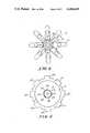
- FIG. 2is a plan view of a contact spring utilized in the device of FIG. 1;
- FIG. 3is a side elevation of the contact spring of FIG. 2;
- FIG. 4is a bottom view of a handle member of FIG. 1;
- FIG. 5is a top plan view of a contact actuating member which is interposed between the contact spring of FIGS. 2 and 3 and the handle member of FIG. 4;
- FIG. 6is a sectional side elevation of a portion of the assembly of FIG. 1;
- FIG. 7is a plan view of a substrate useful in the assembly of FIG. 1.
- a joystick controlleras shown in FIG. 1, includes a handle portion 11, a substrate 12, having a plurality of electrical contacts 13 disposed about the longitudinal axis of handle member 11. Disposed above the contacts 13 is a spring contact member 14 having eight equiangularly radially extending arms 15 (FIG. 2). A generally rectangular opening 16 is defined in substrate 12 which receives depending legs 17 of contact member 14 with the arms 15 positioned above each of switch contacts 13.
- a pivot providing member 18has a lower projection 19 which is received in opening 16, and an upwardly extending pivot providing portion 20. Member 18 is secured to substrate, as shown, by a bolt or screw 21. A surface 22 of member 18, overlies member 14 and substrate 12. As shown in FIG. 5, member 18 has eight radially extending, equiangularly spaced arms 23. Each arm has a substantially hemispherical projection 24 on the upper surface thereof, spaced radially inwardly from the extremities of each of the arms 23. Each of the arms 23 also has a lower projection 25 spaced inwardly from the extremity thereof. The projections 25 are aligned with and adapted to extend through apertures 26 in each arm of spring contact number 14 for purposes hereinafter described. Each of the arms 23 also includes at the extremity thereof a portion of increased thickness 27 which is in substantial contact with an associated arm 15 of spring contact member 14.
- the handle member 11comprises a stem portion 30 having a member 31 thereon.
- Member 31has a flange 32 on the lower end thereof.
- a well or recess 33is defined centrally in member 31.
- handle member 11comprises a three part hand grip 34 which comprises a lower member 35 fitted on a shoulder 36 defined on stem 30.
- An intermediate member 37is matingly fitted to member 35 and secured to stem 30 as by means of a lock washer 38.
- a top member 39has depending legs 40 to lock to member.
- the controller 10may be arranged so that there is only one switch contact to be actuated at a time.
- the pivot providing portion 20(FIG. 5) is formed with equiangularly spaced lands or surfaces 41-48 of trapezoidal shape. Surfaces 41-48 are upwardly and inwardly inclined toward the upper edges thereof. The edges defining well 33 in member 31 have surfaces 41a-48a matingly formed with respect to surfaces 41-48. When the handle 11 with member 31 is fitted to the pivot providing member 20, the surfaces 41-48 and 41a-48a will be in substantial registry.
- Substrate 12together with an upper wall member 50, are spaced and joined by a plurality of columns 51.
- a helical spring 52 resting on surface 53 of wall member 50biases flange portion 32 of member 31 downwardly and the handle into contact with the projections 24 on arms 15. This urges the surfaces 41-48 and 41a-48a, respectively into engagement.
- the handle 11can only be tilted in eight directions and may only activate one of contacts 13 at a time.
- the flange 32 of handle 11is defined with equiangularly radially extending arms 41b-48b, as most clearly seen in FIG. 4. Each of the arms 41b-48b may actuate an arm 23 of member 18, and an arm 15 of spring contact 14.
- one of arms 41b-48bdepress an arm 23 by acting on its upward projection 24 and cause portion 27 of the arm to move an arm 15 of contact number 14 into electrical engagement with a substrate contact 13 and complete an electrical circuit. If a sufficient tilting force is applied, the end of an arm 23 will tend to bend upwardly as a lower projection 25 extends through an aperture 26 of an arm 15 and the arm 15 bottoms on a contact 13 on substrate 12. When this occurs, any additional tilting force applied to the member 31 through handle 11 is transferred directly to the substrate and thus limits the force that can be applied through portion 27 of an arm 15 to a contact 13 on substrate 12.
- the joystick controlleris adapted to control eight directions of motion of an object which may be an image or a marker on a CRT screen.
- the joystick controllermay be arranged to make eight different contacts, each spaced forty-five degrees from the other to signify eight different directions of movement.
- a joystick controller embodying the inventionmay also be utilized with a system where the intermediate directions are sensed by simultaneous closure of two adjacent cardinal contacts.
- the substrate contactsare arranged, as shown in FIG. 7, where the contacts are labeled by direction N, S, E, W, etc. for the cardinal directions.
- the contacts for N'E'; S'E'; S'W'; and N'W' directions for NE, SE, SW, and NWcomprise a pair of contacts, each contact electrically connected to adjacent cardinal direction contacts.
- the spring contact arms 15are sufficiently wide to span the two contacts intermediate the cardinal contacts. Each pair of intermediate contacts may be considered a single intermediate contact.
Landscapes
- Physics & Mathematics (AREA)
- General Physics & Mathematics (AREA)
- Engineering & Computer Science (AREA)
- Automation & Control Theory (AREA)
- Position Input By Displaying (AREA)
- Switches With Compound Operations (AREA)
- Mechanical Control Devices (AREA)
Abstract
Description
Claims (8)
Priority Applications (2)
| Application Number | Priority Date | Filing Date | Title |
|---|---|---|---|
| US06/514,598US4486629A (en) | 1983-07-18 | 1983-07-18 | Joystick controller |
| CA000456278ACA1232308A (en) | 1983-07-18 | 1984-06-11 | Joystick controller |
Applications Claiming Priority (1)
| Application Number | Priority Date | Filing Date | Title |
|---|---|---|---|
| US06/514,598US4486629A (en) | 1983-07-18 | 1983-07-18 | Joystick controller |
Publications (1)
| Publication Number | Publication Date |
|---|---|
| US4486629Atrue US4486629A (en) | 1984-12-04 |
Family
ID=24047888
Family Applications (1)
| Application Number | Title | Priority Date | Filing Date |
|---|---|---|---|
| US06/514,598Expired - LifetimeUS4486629A (en) | 1983-07-18 | 1983-07-18 | Joystick controller |
Country Status (2)
| Country | Link |
|---|---|
| US (1) | US4486629A (en) |
| CA (1) | CA1232308A (en) |
Cited By (19)
| Publication number | Priority date | Publication date | Assignee | Title |
|---|---|---|---|---|
| US4575591A (en)* | 1984-04-23 | 1986-03-11 | Lugaresi Thomas J | Joystick attachment for a computer keyboard |
| US4896003A (en)* | 1989-06-30 | 1990-01-23 | Hsieh Man Ching | Multi-position electrical switch |
| US5086313A (en)* | 1988-01-28 | 1992-02-04 | Asahi Kogaku Kogyo Kabushiki Kaisha | Operation switch unit for a camera |
| US5164554A (en)* | 1990-07-10 | 1992-11-17 | Mitsubishi Denki Kabushiki Kaisha | Pivotable pushbutton operated multiple switch assembly |
| US5396030A (en)* | 1992-07-31 | 1995-03-07 | Sega Enterprises, Ltd. | Selective multiple position switch with common pivoted operator |
| DE4443726A1 (en)* | 1993-12-08 | 1995-06-14 | Alps Electric Co Ltd | Multidirectional input switch |
| US5516991A (en)* | 1993-11-26 | 1996-05-14 | Bausch & Lomb Incorporated | Multiple position manual switch |
| US5541622A (en)* | 1990-07-24 | 1996-07-30 | Incontrol Solutions, Inc. | Miniature isometric joystick |
| US5766079A (en)* | 1994-06-20 | 1998-06-16 | Sega Enterprises Ltd. | Object direction control method and apparatus |
| US5805138A (en)* | 1995-06-07 | 1998-09-08 | International Business Machines Corporation | Gross motion input controller for a computer system |
| EP0785499A4 (en)* | 1995-05-10 | 1999-01-07 | Nintendo Co Ltd | Image processing system using analog joystick |
| US5889242A (en)* | 1996-10-17 | 1999-03-30 | Matsushita Electric Industrial Co., Ltd. | Multidirectional operating switch and multidirectional operating apparatus using the same |
| US5952631A (en)* | 1995-11-30 | 1999-09-14 | Sega Enterprises, Ltd. | Switch device |
| US6394906B1 (en)* | 1997-09-22 | 2002-05-28 | Sony Computer Entertainment Inc. | Actuating device for game machine |
| US6403898B2 (en)* | 2000-06-02 | 2002-06-11 | Itt Manufacturing Enterprises, Inc. | Multiple switch assembly |
| DE19517538C2 (en)* | 1994-05-12 | 2003-01-23 | Alps Electric Co Ltd | Multi-toggle switch |
| US20030160761A1 (en)* | 2002-02-22 | 2003-08-28 | Donald Wu | Joystick having pressure-activated switch |
| US20060278503A1 (en)* | 2003-06-26 | 2006-12-14 | Jonge Johannes D | Switch dome device |
| US20090239665A1 (en)* | 2007-12-31 | 2009-09-24 | Michael Minuto | Brandable thumbstick cover for game controllers |
Citations (13)
| Publication number | Priority date | Publication date | Assignee | Title |
|---|---|---|---|---|
| US2857485A (en)* | 1956-10-24 | 1958-10-21 | Martin Co | Multi-position electrical switch |
| US3005055A (en)* | 1957-10-08 | 1961-10-17 | Bell Telephone Labor Inc | Tilting dial circuit selector |
| US3033946A (en)* | 1960-04-06 | 1962-05-08 | Gen Motors Corp | Circuit controller |
| US4091234A (en)* | 1977-03-30 | 1978-05-23 | Atari, Inc. | Joystick with attached circuit elements |
| US4124787A (en)* | 1977-03-11 | 1978-11-07 | Atari, Inc. | Joystick controller mechanism operating one or plural switches sequentially or simultaneously |
| US4148014A (en)* | 1977-04-06 | 1979-04-03 | Texas Instruments Incorporated | System with joystick to control velocity vector of a display cursor |
| DD148123A1 (en)* | 1979-12-17 | 1981-05-06 | Guenter Schieferdecker | MULTIPLE SPRING ELEMENT FOR AN ELECTRIC SWITCHEL |
| US4275611A (en)* | 1979-03-29 | 1981-06-30 | Atari, Inc. | Joystick controller |
| US4319099A (en)* | 1979-05-03 | 1982-03-09 | Atari, Inc. | Dome switch having contacts offering extended wear |
| US4386776A (en)* | 1981-02-17 | 1983-06-07 | Coleco Industries, Inc. | Electronic sports-action game with improved game-object simulation |
| US4394548A (en)* | 1982-03-08 | 1983-07-19 | Amp Incorporated | Joystick switch |
| US4408103A (en)* | 1982-01-06 | 1983-10-04 | Smith Engineering | Joystick operated multiple position switch |
| US4439648A (en)* | 1982-07-28 | 1984-03-27 | Coleco Industries, Inc. | Joystick-type controller |
- 1983
- 1983-07-18USUS06/514,598patent/US4486629A/ennot_activeExpired - Lifetime
- 1984
- 1984-06-11CACA000456278Apatent/CA1232308A/ennot_activeExpired
Patent Citations (13)
| Publication number | Priority date | Publication date | Assignee | Title |
|---|---|---|---|---|
| US2857485A (en)* | 1956-10-24 | 1958-10-21 | Martin Co | Multi-position electrical switch |
| US3005055A (en)* | 1957-10-08 | 1961-10-17 | Bell Telephone Labor Inc | Tilting dial circuit selector |
| US3033946A (en)* | 1960-04-06 | 1962-05-08 | Gen Motors Corp | Circuit controller |
| US4124787A (en)* | 1977-03-11 | 1978-11-07 | Atari, Inc. | Joystick controller mechanism operating one or plural switches sequentially or simultaneously |
| US4091234A (en)* | 1977-03-30 | 1978-05-23 | Atari, Inc. | Joystick with attached circuit elements |
| US4148014A (en)* | 1977-04-06 | 1979-04-03 | Texas Instruments Incorporated | System with joystick to control velocity vector of a display cursor |
| US4275611A (en)* | 1979-03-29 | 1981-06-30 | Atari, Inc. | Joystick controller |
| US4319099A (en)* | 1979-05-03 | 1982-03-09 | Atari, Inc. | Dome switch having contacts offering extended wear |
| DD148123A1 (en)* | 1979-12-17 | 1981-05-06 | Guenter Schieferdecker | MULTIPLE SPRING ELEMENT FOR AN ELECTRIC SWITCHEL |
| US4386776A (en)* | 1981-02-17 | 1983-06-07 | Coleco Industries, Inc. | Electronic sports-action game with improved game-object simulation |
| US4408103A (en)* | 1982-01-06 | 1983-10-04 | Smith Engineering | Joystick operated multiple position switch |
| US4394548A (en)* | 1982-03-08 | 1983-07-19 | Amp Incorporated | Joystick switch |
| US4439648A (en)* | 1982-07-28 | 1984-03-27 | Coleco Industries, Inc. | Joystick-type controller |
Cited By (28)
| Publication number | Priority date | Publication date | Assignee | Title |
|---|---|---|---|---|
| US4575591A (en)* | 1984-04-23 | 1986-03-11 | Lugaresi Thomas J | Joystick attachment for a computer keyboard |
| US5086313A (en)* | 1988-01-28 | 1992-02-04 | Asahi Kogaku Kogyo Kabushiki Kaisha | Operation switch unit for a camera |
| US4896003A (en)* | 1989-06-30 | 1990-01-23 | Hsieh Man Ching | Multi-position electrical switch |
| US5164554A (en)* | 1990-07-10 | 1992-11-17 | Mitsubishi Denki Kabushiki Kaisha | Pivotable pushbutton operated multiple switch assembly |
| US5889507A (en)* | 1990-07-24 | 1999-03-30 | Incontrol Solutions, Inc. | Miniature isometric joystick |
| US5541622A (en)* | 1990-07-24 | 1996-07-30 | Incontrol Solutions, Inc. | Miniature isometric joystick |
| US5396030A (en)* | 1992-07-31 | 1995-03-07 | Sega Enterprises, Ltd. | Selective multiple position switch with common pivoted operator |
| US5525770A (en)* | 1992-07-31 | 1996-06-11 | Sega Enterprises, Ltd. | Control-key mechanism having improved operation feeling |
| USRE36349E (en)* | 1992-07-31 | 1999-10-26 | Sega Enterprises | Control-key mechanism having improved operation feeling |
| USRE36738E (en)* | 1992-07-31 | 2000-06-20 | Sega Enterprises, Ltd. | Selective multiple position switch with common pivoted operator |
| US5516991A (en)* | 1993-11-26 | 1996-05-14 | Bausch & Lomb Incorporated | Multiple position manual switch |
| DE4443726C2 (en)* | 1993-12-08 | 2002-08-01 | Alps Electric Co Ltd | Multi-directional input switch |
| DE4443726A1 (en)* | 1993-12-08 | 1995-06-14 | Alps Electric Co Ltd | Multidirectional input switch |
| DE19517538C2 (en)* | 1994-05-12 | 2003-01-23 | Alps Electric Co Ltd | Multi-toggle switch |
| US5766079A (en)* | 1994-06-20 | 1998-06-16 | Sega Enterprises Ltd. | Object direction control method and apparatus |
| US5971853A (en)* | 1994-06-20 | 1999-10-26 | Kabushiki Kaisha Sega Enterprises | Object direction control method and apparatus |
| EP0785499A4 (en)* | 1995-05-10 | 1999-01-07 | Nintendo Co Ltd | Image processing system using analog joystick |
| US5805138A (en)* | 1995-06-07 | 1998-09-08 | International Business Machines Corporation | Gross motion input controller for a computer system |
| US5952631A (en)* | 1995-11-30 | 1999-09-14 | Sega Enterprises, Ltd. | Switch device |
| EP0837419A3 (en)* | 1996-10-17 | 2002-11-06 | Matsushita Electric Industrial Co., Ltd. | Multidirectional operating switch and multidirectional operating apparatus using the same |
| US5889242A (en)* | 1996-10-17 | 1999-03-30 | Matsushita Electric Industrial Co., Ltd. | Multidirectional operating switch and multidirectional operating apparatus using the same |
| US6394906B1 (en)* | 1997-09-22 | 2002-05-28 | Sony Computer Entertainment Inc. | Actuating device for game machine |
| US6403898B2 (en)* | 2000-06-02 | 2002-06-11 | Itt Manufacturing Enterprises, Inc. | Multiple switch assembly |
| US20030160761A1 (en)* | 2002-02-22 | 2003-08-28 | Donald Wu | Joystick having pressure-activated switch |
| US20060278503A1 (en)* | 2003-06-26 | 2006-12-14 | Jonge Johannes D | Switch dome device |
| US7663068B2 (en) | 2003-06-26 | 2010-02-16 | Sony Ericsson Mobile Communications Ab | Switch dome device |
| CN1813326B (en)* | 2003-06-26 | 2010-06-16 | 索尼爱立信移动通讯股份有限公司 | Convert Dome Unit |
| US20090239665A1 (en)* | 2007-12-31 | 2009-09-24 | Michael Minuto | Brandable thumbstick cover for game controllers |
Also Published As
| Publication number | Publication date |
|---|---|
| CA1232308A (en) | 1988-02-02 |
Similar Documents
| Publication | Publication Date | Title |
|---|---|---|
| US4486629A (en) | Joystick controller | |
| US4439648A (en) | Joystick-type controller | |
| US4992631A (en) | Multi-directional switch assembly | |
| US5294121A (en) | Direction control key assembly | |
| US5034574A (en) | Joystick for computer keyboards | |
| EP0024813B1 (en) | Joystick controller | |
| CA1249320A (en) | Hand operable controller | |
| US4439649A (en) | Joy stick switch | |
| US4687200A (en) | Multi-directional switch | |
| EP0632475B1 (en) | Joy stick support structure for multidirectional switch | |
| US6589118B1 (en) | Analog input device to input multi directional signals | |
| US4256931A (en) | Multiple dome switch assembly having pivotable common actuator | |
| US4492830A (en) | Joystick with single-leaf spring switch | |
| US6794589B2 (en) | Multiple electrical switch arrangement | |
| US5283401A (en) | Multiple switch assembly including lockable and/or vertically movable switch actuator | |
| US4394548A (en) | Joystick switch | |
| GB1558660A (en) | Joystick controller assembly for electrical switches | |
| US4604502A (en) | Joystick control | |
| EP0205726B1 (en) | Image controlling method and device for carrying out the same | |
| JP2002042612A (en) | Operation device | |
| EP0121866A2 (en) | Keyboard joyswitch | |
| US4816622A (en) | Joystick assemblies | |
| JP2916867B2 (en) | Multi-directional input switch | |
| WO1993007633A1 (en) | Joystick | |
| EP0683499B1 (en) | Control key device |
Legal Events
| Date | Code | Title | Description |
|---|---|---|---|
| AS | Assignment | Owner name:TOKYO SHIBAURA DENKI KABUSHIKI KAISHA, 72 HORIKAWA Free format text:ASSIGNMENT OF ASSIGNORS INTEREST.;ASSIGNORS:KAMEYAMA, SHUICHI;KANZAKI, KOICHI;SASAKI, YOSHITAKA;REEL/FRAME:004201/0206 Effective date:19820430 | |
| AS | Assignment | Owner name:COLECO INDUSTRIES, INC., 945 ASYLUM AVENUE, HARTFO Free format text:ASSIGNMENT OF ASSIGNORS INTEREST.;ASSIGNOR:SLEDESKY, STEPHEN M.;REEL/FRAME:004202/0014 Effective date:19830707 | |
| AS | Assignment | Owner name:CHASE MANHATTAN BANK, THE (NATIONAL ASSOCIATION), Free format text:SECURITY INTEREST;ASSIGNOR:COLECO INDUSTRIES, INC.;REEL/FRAME:004304/0617 Effective date:19831231 | |
| STCF | Information on status: patent grant | Free format text:PATENTED CASE | |
| AS | Assignment | Owner name:CONNECTICUT NATIONAL BANK, THE, 777 MAIN ST., HART Free format text:SECURITY INTEREST;ASSIGNOR:COLECO INDUSTRIES, INC., A CORP. OF CT.;REEL/FRAME:004613/0330 Effective date:19860801 Owner name:NATIONAL BANK OF CANADA, 535 MADISON AVE., NEW YOR Free format text:SECURITY INTEREST;ASSIGNOR:COLECO INDUSTRIES, INC., A CORP. OF CT.;REEL/FRAME:004613/0330 Effective date:19860801 | |
| AS | Assignment | Owner name:TOY FUNDING CORPORATION, 45 BROADWAY NEW YORK, NEW Free format text:LIEN;ASSIGNOR:COLECO INDUSTRIES, INC., A CT. CORP.;REEL/FRAME:004727/0929 Effective date:19870610 Owner name:BANQUE INDOSUEZ, 1230 AVENUE OF THE AMERICAS, NEW Free format text:LIEN;ASSIGNOR:COLECO INDUSTRIES, INC., A CT. CORP.;REEL/FRAME:004727/0929 Effective date:19870610 Owner name:SOCIETE GENERALE, 50 ROCKEFELLER PLAZA, NEW YORK, Free format text:LIEN;ASSIGNOR:COLECO INDUSTRIES, INC., A CT. CORP.;REEL/FRAME:004727/0929 Effective date:19870610 Owner name:CREDIT LYONNAIS, 95 WALL STREET, NEW YORK, NEW YOR Free format text:LIEN;ASSIGNOR:COLECO INDUSTRIES, INC., A CT. CORP.;REEL/FRAME:004727/0929 Effective date:19870610 Owner name:DAI-ICHI KANGYO BANK, LIMITED, THE, 1 WORLD TRADE Free format text:LIEN;ASSIGNOR:COLECO INDUSTRIES, INC., A CT. CORP.;REEL/FRAME:004727/0929 Effective date:19870610 Owner name:TOY FUNDING CORPORATION, A CORP. OF DE.,NEW YORK Free format text:LIEN;ASSIGNOR:COLECO INDUSTRIES, INC., A CT. CORP.;REEL/FRAME:004727/0929 Effective date:19870610 Owner name:BANQUE INDOSUEZ, A FRENCH BANKING CORP.,NEW YORK Free format text:LIEN;ASSIGNOR:COLECO INDUSTRIES, INC., A CT. CORP.;REEL/FRAME:004727/0929 Effective date:19870610 Owner name:SOCIETE GENERALE, A FRENCH BANKING CORP.,NEW YORK Free format text:LIEN;ASSIGNOR:COLECO INDUSTRIES, INC., A CT. CORP.;REEL/FRAME:004727/0929 Effective date:19870610 Owner name:CREDIT LYONNAIS, A FRENCH BANKING CORP.,NEW YORK Free format text:LIEN;ASSIGNOR:COLECO INDUSTRIES, INC., A CT. CORP.;REEL/FRAME:004727/0929 Effective date:19870610 Owner name:DAI-ICHI KANGYO BANK, LIMITED, THE, A JAPANESE BAN Free format text:LIEN;ASSIGNOR:COLECO INDUSTRIES, INC., A CT. CORP.;REEL/FRAME:004727/0929 Effective date:19870610 Owner name:TOY FUNDING CORPORATION, A CORP. OF DE., NEW YORK Free format text:LIEN;ASSIGNOR:COLECO INDUSTRIES, INC., A CT. CORP.;REEL/FRAME:004727/0929 Effective date:19870610 Owner name:BANQUE INDOSUEZ, A FRENCH BANKING CORP., NEW YORK Free format text:LIEN;ASSIGNOR:COLECO INDUSTRIES, INC., A CT. CORP.;REEL/FRAME:004727/0929 Effective date:19870610 Owner name:SOCIETE GENERALE, A FRENCH BANKING CORP., NEW YORK Free format text:LIEN;ASSIGNOR:COLECO INDUSTRIES, INC., A CT. CORP.;REEL/FRAME:004727/0929 Effective date:19870610 Owner name:CREDIT LYONNAIS, A FRENCH BANKING CORP., NEW YORK Free format text:LIEN;ASSIGNOR:COLECO INDUSTRIES, INC., A CT. CORP.;REEL/FRAME:004727/0929 Effective date:19870610 Owner name:DAI-ICHI KANGYO BANK, LIMITED, THE, A JAPANESE BANKING CORP., NEW YORK Free format text:LIEN;ASSIGNOR:COLECO INDUSTRIES, INC., A CT. CORP.;REEL/FRAME:004727/0929 Effective date:19870610 | |
| FEPP | Fee payment procedure | Free format text:PAYOR NUMBER ASSIGNED (ORIGINAL EVENT CODE: ASPN); ENTITY STATUS OF PATENT OWNER: LARGE ENTITY | |
| FPAY | Fee payment | Year of fee payment:4 | |
| AS | Assignment | Owner name:CONGRESS FINANCIAL CORPORATION, NEW YORK Free format text:SECURITY INTEREST;ASSIGNORS:COLECO INDUSTRIES, INC., DEBTORS-IN-POSSESSION;SELCHOW & RIGHTER COMPANY, DEBTORS AND DEBTORS-IN-POSSESSION;LAKESIDE INDUSTRIES, INC., DEBTORS AND DEBTORS-IN-POSSESSION;REEL/FRAME:005050/0658 Effective date:19880805 | |
| AS | Assignment | Owner name:COLECO INDUSTRIES, INC. Free format text:RELEASED BY SECURED PARTY;ASSIGNOR:TOY FUNDING CORPORATION;REEL/FRAME:005159/0928 Effective date:19890707 Owner name:MILTON BRADLEY COMPANY, A CORP. OF MA, MASSACHUSET Free format text:ASSIGNMENT OF ASSIGNORS INTEREST.;ASSIGNOR:COLECO INDUSTRIES, INC.;REEL/FRAME:005159/0151 Effective date:19890712 Owner name:COLECO INDUSTRIES, INC., Free format text:RELEASED BY SECURED PARTY;ASSIGNOR:CONNECTICUT NATIONAL BANK;REEL/FRAME:005244/0368 Effective date:19890707 Owner name:LAKESIDE INDUSTRIES, INC. Free format text:RELEASED BY SECURED PARTY;ASSIGNOR:CONNECTICUT NATIONAL BANK;REEL/FRAME:005240/0501 Effective date:19890707 | |
| FEPP | Fee payment procedure | Free format text:PAYER NUMBER DE-ASSIGNED (ORIGINAL EVENT CODE: RMPN); ENTITY STATUS OF PATENT OWNER: LARGE ENTITY Free format text:PAYOR NUMBER ASSIGNED (ORIGINAL EVENT CODE: ASPN); ENTITY STATUS OF PATENT OWNER: LARGE ENTITY | |
| FPAY | Fee payment | Year of fee payment:8 | |
| AS | Assignment | Owner name:HASBRO, INC., RHODE ISLAND Free format text:MERGER;ASSIGNOR:MILTON BRADLEY COMPANY;REEL/FRAME:007656/0793 Effective date:19941201 | |
| FEPP | Fee payment procedure | Free format text:PAYER NUMBER DE-ASSIGNED (ORIGINAL EVENT CODE: RMPN); ENTITY STATUS OF PATENT OWNER: LARGE ENTITY Free format text:PAYOR NUMBER ASSIGNED (ORIGINAL EVENT CODE: ASPN); ENTITY STATUS OF PATENT OWNER: LARGE ENTITY | |
| FPAY | Fee payment | Year of fee payment:12 |