US4485678A - Rotor diagnostic and balancing system - Google Patents
Rotor diagnostic and balancing systemDownload PDFInfo
- Publication number
- US4485678A US4485678AUS06/423,503US42350382AUS4485678AUS 4485678 AUS4485678 AUS 4485678AUS 42350382 AUS42350382 AUS 42350382AUS 4485678 AUS4485678 AUS 4485678A
- Authority
- US
- United States
- Prior art keywords
- rotor
- data
- vibration
- vibrational
- rotors
- Prior art date
- Legal status (The legal status is an assumption and is not a legal conclusion. Google has not performed a legal analysis and makes no representation as to the accuracy of the status listed.)
- Expired - Fee Related
Links
- 238000000034methodMethods0.000claimsdescription12
- 230000001360synchronised effectEffects0.000claimsdescription10
- 238000012544monitoring processMethods0.000claimsdescription7
- 238000001228spectrumMethods0.000claimsdescription7
- 230000003247decreasing effectEffects0.000claims2
- 230000035945sensitivityEffects0.000claims2
- 238000012360testing methodMethods0.000description18
- 230000001052transient effectEffects0.000description5
- 238000010586diagramMethods0.000description4
- 230000006870functionEffects0.000description3
- 238000009434installationMethods0.000description3
- 238000010183spectrum analysisMethods0.000description3
- 238000004891communicationMethods0.000description2
- 238000002405diagnostic procedureMethods0.000description2
- 238000005259measurementMethods0.000description2
- 238000012545processingMethods0.000description2
- 230000001133accelerationEffects0.000description1
- 238000012937correctionMethods0.000description1
- 230000007547defectEffects0.000description1
- 230000001419dependent effectEffects0.000description1
- 239000000446fuelSubstances0.000description1
- 238000004519manufacturing processMethods0.000description1
- 238000013102re-testMethods0.000description1
- 230000000306recurrent effectEffects0.000description1
- 230000004044responseEffects0.000description1
- 239000000523sampleSubstances0.000description1
Images


Classifications
- G—PHYSICS
- G01—MEASURING; TESTING
- G01H—MEASUREMENT OF MECHANICAL VIBRATIONS OR ULTRASONIC, SONIC OR INFRASONIC WAVES
- G01H1/00—Measuring characteristics of vibrations in solids by using direct conduction to the detector
- G01H1/003—Measuring characteristics of vibrations in solids by using direct conduction to the detector of rotating machines
Definitions
- the present inventionis directed towards providing a means of testing, analyzing and correcting rotor vibrations.
- a recurrent problem in the manufacture, testing, installation, and operation of rotating machineryis the need to balance the rotor.
- the balancing procedure involvedis usually referred to as field balancing, trim balancing, or in-place balancing when performed in the test cell or in the final installation.
- Factory balancing in traditional low-speed machinesusually involves general sensors (integral parts of the balancing machine) used to identify balance corrections in one or at most two locations along the rotor's shaft axis.
- the ability and accuracy in determining and correcting vibrations due to an unbalanced rotorbecomes more and more critical to satisfactory operation of the device.
- the whole engineis returned to the final assembly area for corrective rework.
- the present inventionprovides for testing and trim balancing to be done in a relatively short period and to provide a diagnostic function which ascertains the probable cause of the vibration to expedite rework if necessary.
- the present inventionrequires only the speed data and vibration signature of the rotor to evaluate the rotor's operation.
- Four basic predetermined criteriadetermine the cause of any vibrations. These criteria analyze the vibration data provided at various transient and steady state speeds by a plurality of vibration sensors or probes positioned on the engine casing about the rotor(s) (high and low pressure rotors may be involved in jet engines).
- the first criteriadetermines the location of the maximum vibration by determining at what sensor location the strongest or highest vibration appears. For example, if the first of two vibration sensors is positioned at the compressor end of a rotor and the second at the turbine end, and if the first sensor showed high vibrations, the cause of the vibrations would probably be at the compressor end of the rotor.
- a second diagnostic criteriainvolves transient measurement analysis, that is, for example varying the speed of the engine and rotor from idle up to full speed (just prior to the first critical speed to just beyond the second critical speed of the low pressure rotor), and back down again. If there is a discontinuous or abrupt change in vibration as the rotors' speed changes, this indicates a rotor shift.
- the third criteriainvolves frequency domain analysis at different steady state speeds. This involves a spectrum analysis of vibration signal frame the rotor rotating at predetermined steady state speeds, so as to determine the frequency components of the vibration and their source.
- the last criteriainvolves analysis of critical speed maps in which the rotor itself and the various components coupled to the rotor provide a maximum vibration at a select critical speed (which is usually predetermined by the manufacturer) for comparison to the theoretical. Misalignment rather than unbalance would be indicated by vibration frequencies at two times the expected frequency.
- the unbalanceis the type that can be corrected by trim balancing (i.e., unbalance in an accessible area and not due to rotor shifting, misalignment, etc.) Then a somewhat standard trim balancing technique would be performed.
- trim balancingi.e., unbalance in an accessible area and not due to rotor shifting, misalignment, etc.
- trim balancingi.e., unbalance in an accessible area and not due to rotor shifting, misalignment, etc.
- trim balancingi.e., unbalance in an accessible area and not due to rotor shifting, misalignment, etc.
- FIG. 1is a block diagram of the system for performing rotor diagnostics and trim balancing, incorporating the teachings of the present invention
- FIG. 2is a block diagram flow chart of the steps involved in rotor diagnostics, incorporating the teachings of the present invention.
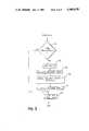
- FIG. 3is a block diagram flow chart of trim balancing a rotor, printout and storage of rotor data.
- the present inventionis directed towards first providing a diagnostic function to ascertain if the rotor of an engine can be trim balanced and second, if so, to trim balance it.
- trim balancingis not effective or possible. Typically, this occurs when no trim balance locations are accessible without engine disassembly (such as the core of a turbofan), when the engine is not provided with trim balancing locations, or when the high vibration levels cannot be corrected by balancing alone such as where rotor shift or misalignment is involved.
- the diagnostic procedure of this inventionis advantageous to identify the source of engine vibration, to minimize the trial-and-error in reworking and avoid multiple engine retest procedures. By isolating the sources of excess vibration, the system increases the productivity of testing and reduces the amount of fuel consumed during engine test. The end result is that more engines are available for service at reduced cost.
- FIG. 1there is depicted the overall system 10 which is coupled to an engine 12 to be tested.
- the present systemis particularly useful in analyzing a jet engine.
- high and low pressure rotorsare involved therein and as such will be used as an example throughout the disclosure herein.
- the present inventionis not limited to jet engines but is applicable to all types of rotor or multiple-stage rotor applications.
- a plurality of vibration pickup sensors 14are provided. These sensors are coupled to a signal conditioner 16 and provide analog vibration signals thereto.
- the number of sensors and their locationmay vary. Consideration should be given to the dynamic characteristics and the theoretical responses of the particular rotor in choosing the number and location of the sensors needed.
- three sensors(V 1 , V 2 , V 3 ) are mounted on the casing of the engine; V 1 adjacent the compressor end of the low pressure rotor, V 3 adjacent the low pressure turbine end; and V 2 in between V 1 and V 3 adjacent to the high pressure rotor.
- Processor 22may be for example a DEC PDP 11/03 CPU with a MOS memory such as the MSLL-64KB memory module, or any other equipment suitable for purpose.
- the digital signal processor 22controls the acquisition and processing of data from the vibration and rotor speed sensors on the jet engine under test.
- a programmable clockcan be used in processor 22 to synchronize the rotor speed and the vibration data. This of course would be in addition to A/D (Analog to Digital) convertors, filters and other conventional apparatus for proper operation.
- A/DAnalog to Digital
- the particular signal processing functions of the processor 22are controlled by command links 23.
- the data collected by the processor 22is transmitted via data links 24 to the computer 20 for diagnostic purposes in its diagnostic and balancing logic section 26 and storage in the archive memory section 28A and/or memory 28B.
- Communication lines with the computer 20may be serial RS-232 communication links or any other means suitable for the purpose.
- FIG. 2sets forth a representation flow diagram of the diagnostic analysis which would be performed by the diagnostic and balancing logic section 26 of the computer 20. This flow chart corresponds to the four basic criteria in the rotor diagnostic analysis.
- the first of these criteriainvolves determining which sensor V 1 , V 2 , V 3 records the maximum vibration.
- the engineis accelerated from idle speed to full speed (32), with full speed being just after the second critical speed of the low pressure rotor.
- a readingwould be taken at every 100 RPM interval as determined by the rotor speed sensors N 1 and N 2 which are synchronized by the clock.
- a large set of data samplesis acquired from each of the vibration sensors during a single revolution of each rotor. This is accomplished by synchronizing the acquisition of vibration sensor output using the programmable clock and the A/D converters.
- the N 1 rotor synchronous frequency component of the V 1 sensoris scanned for occurrence of a peak or maximum vibration over the speed range of engine operation. If the maximum vibration occurs, for example, in some predetermined range of the low pressure rotor such as approximately 7000 RPM to full speed then this indicates a low pressure rotor unbalance within its compressor stages. Similarly, if the maximum vibrations occurred between idle and approximately 7000 RPM, then this would indicate a change in flexibility of the low pressure rotor.
- the maximum vibrations on sensor V 2are determined. If the maximum components that are synchronous with the N 2 rotor occur in the speed range of idle to approximately 10,000 RPM, then this indicates that the high pressure rotors turbine side is unbalanced. If the maximum vibration component that is synchronous with the N 2 rotor occurs in the speed range of 10,000 RPM to full speed, this would indicate unbalance at the high pressure rotor on its compressor side.
- the second criteriais transient measurement analysis (42).
- the vibrations at the sensors V 1 , V 2 , V 3 under the previously described transient (run up and run down) operating conditionsare monitored for vibrations that change abruptly or discontinuously with an increase or decrease in speed.
- a discontinuity of greater than 1.5 mils in the vibration at V 1 for a change of 200 RPM in speed sensor signal of N 1would indicate a shift in the low pressure rotor at the compressor;
- a discontinuity at V 3would indicate a shift in the low pressure rotor at the turbine;
- at a discontinuity of greater than 1.5 mils at V 2 for a change of 200 RPM in the signal of N 2would indicate a shift in the high pressure rotor.
- the speed of the engine and rotorswould be returned to idle (44) at which time if so desired, a display or other output (not shown) of the computer 20 may be provided of the data accumulated up to this point.
- the output 70could take on a variety of forms such as video, graphic, hard copy, or standard line printer if so desired.
- a third criteriais involved in the present system which is directed towards determining a spectrum analysis of the steady state data of the frequency domain of vibration and its components.
- a rotorbehaves much differently in a transient state (that is when the speed is continuously changing) and a steady state (when it is run at the same speed for a time).
- Such a spectrum analysis of vibrationscan be provided for example by a device manufactured by Hewlett Packard, entitled “Spectrum Analyzer” Model No. 5200. In this regard, once the idle speed is set, then the collection of steady state vibration data (46) begins.
- the speed of the engine and rotorsis incrementally (7000, 8000, 9000 full RPM) brought up at fixed intervals of predetermined duration (approximately 3 min.) from idle to a maximum vibration speed.
- the amplitude of the vibration signals from the sensors V 1 , V 2 , V 3 at these predetermined speeds of the rotorsare monitored to provide the frequency domain for the rotor's operation.
- the frequency of the signalsare doubled since vibration due to misalignment would exist at twice the frequency of vibration due to unbalance. Additionally, accessory frequencies are monitored.
- the overall vibrations at sensors V 1 , V 2 and V 3are determined by a time-to-frequency Fast Fourier Transform (FFT) spectrum (47) to determine the spectrum contents and to extract the synchronous component amplitude and phase from the data signals.
- FFTFast Fourier Transform
- the amplitude of each known componentprovides its contribution to the overall vibration and serves to identify the component and therefore the location from which the vibrations originate and accordingly whether they can be corrected.
- the theoretical frequenciesare used to identify actual measured vibration frequencies from the dynamic rotor performance. For example, if a measure component of the vibration had a frequency of 10,000 RPM and according to the critical speed map an oil pump coupled to the rotor has a maximum vibration at 10,000 RPM, this would indicate that there was an unbalance at the pump.
- the diagnostic and balancing logic section 26will generate an output (50) via the previous output to set forth the causes of the vibration in an order of greatest probability if so desired, an output report 52 of the same can be printed via a mechanical printer.
- a determination (54)is made whether the vibration is due to unbalancing which can be corrected by trim balancing. If correctable, then a somewhat convention trim balancing can proceed. If it can be corrected then the engine and low pressure rotor is set (56) at an appropriate speed (i.e, 8500 RPM).
- the vibration (amplitude and phase) at V 1 and N 1is determined (58) and the predetermined influence coefficients already stored in storage 28A are used in a standard manner, such as the Sumiville Method, to calculate the balance weight to be used and the location that they are to be placed. Influence coefficients relate vibration amplitude at specific locations and speeds to the mass unbalance at a reference position.
- a data output via 70is provided as to the placement of the appropriate balance weights (60).
- the engine and rotorwould then be test run again (62) at 8500 RPMs to insure proper balancing.
- the data generatedwould be in the form of an output (64) which would include, inter alia, acceleration, deceleration, and FFT plots for each of the sensors V 1 , V 2 and V 3 along with the previously provided data as to the probable cause of the vibrations provided to the operator in printed form, video, or any other form including plots, with this data stored in the archive storage 28A along with previously generated data for this particular engine.
- test datais generated as an output (64) to enable a relatively quick and efficient reworking of the engine.
Landscapes
- Physics & Mathematics (AREA)
- General Physics & Mathematics (AREA)
- Testing Of Balance (AREA)
- Turbine Rotor Nozzle Sealing (AREA)
Abstract
Description
Claims (6)
Priority Applications (1)
| Application Number | Priority Date | Filing Date | Title |
|---|---|---|---|
| US06/423,503US4485678A (en) | 1982-09-27 | 1982-09-27 | Rotor diagnostic and balancing system |
Applications Claiming Priority (1)
| Application Number | Priority Date | Filing Date | Title |
|---|---|---|---|
| US06/423,503US4485678A (en) | 1982-09-27 | 1982-09-27 | Rotor diagnostic and balancing system |
Publications (1)
| Publication Number | Publication Date |
|---|---|
| US4485678Atrue US4485678A (en) | 1984-12-04 |
Family
ID=23679123
Family Applications (1)
| Application Number | Title | Priority Date | Filing Date |
|---|---|---|---|
| US06/423,503Expired - Fee RelatedUS4485678A (en) | 1982-09-27 | 1982-09-27 | Rotor diagnostic and balancing system |
Country Status (1)
| Country | Link |
|---|---|
| US (1) | US4485678A (en) |
Cited By (45)
| Publication number | Priority date | Publication date | Assignee | Title |
|---|---|---|---|---|
| US4643023A (en)* | 1985-11-01 | 1987-02-17 | Capps David F | Vibration testing apparatus |
| US4894787A (en)* | 1988-04-28 | 1990-01-16 | Kaman Aerospace Corporation | Automatic load monitoring system with remote sensing |
| US4937758A (en)* | 1987-09-04 | 1990-06-26 | Technology Integration And Development Group, Inc. | Method and apparatus for reducing vibration over the full operating range of a rotor and a host device |
| US4989159A (en)* | 1988-10-13 | 1991-01-29 | Liszka Ludwik Jan | Machine monitoring method |
| US5172325A (en)* | 1990-08-02 | 1992-12-15 | The Boeing Company | Method for balancing rotating machinery |
| US5214585A (en)* | 1989-06-30 | 1993-05-25 | General Electric Company | Balancing method and product |
| EP0577159A1 (en)* | 1992-06-29 | 1994-01-05 | The Boeing Company | Onboard aircraft engine balancing data gathering and analysis system |
| US5502650A (en)* | 1992-04-01 | 1996-03-26 | Kabushiki Kaisha Toshiba | Apparatus for adjusting rotor |
| US5586065A (en)* | 1994-05-31 | 1996-12-17 | The Boeing Company | Method and apparatus for minimizing aircraft cabin noise |
| EP0771446A4 (en)* | 1994-06-14 | 1997-08-27 | Scientific Atlanta | Method and apparatus for automatically balancing rotating machinery |
| US6027239A (en)* | 1997-04-30 | 2000-02-22 | Endevco Corporation | On-board engine trim balance display and interface |
| WO2003060453A1 (en)* | 2001-12-21 | 2003-07-24 | United States Enrichment Corporation | Method and system for balancing a rotating machinery operating at resonance |
| WO2003056284A3 (en)* | 2001-11-16 | 2003-12-04 | Goodrich Pump & Engine Control | Vibration monitoring system for gas turbine engines |
| US6768938B2 (en) | 2001-11-16 | 2004-07-27 | Goodrich Pump & Engine Control Systems, Inc. | Vibration monitoring system for gas turbine engines |
| US7095243B1 (en) | 2005-07-11 | 2006-08-22 | Honeywell International, Inc. | AC generator exciter rotor slip-ring test apparatus |
| US20090158845A1 (en)* | 2007-12-20 | 2009-06-25 | Van Der Merwe Gert J | Method and apparatus for verifying the operation of an accelerometer |
| CN100538305C (en)* | 2003-04-30 | 2009-09-09 | 通用电气公司 | The system and method for vibration survey and record |
| US20090263247A1 (en)* | 2008-04-21 | 2009-10-22 | Daniel Edward Mollmann | Dual rotor vibration monitoring |
| US7658588B1 (en) | 2006-01-27 | 2010-02-09 | Florida Turbine Technologies, Inc. | Optimized blade tip clearance process for a rub tolerant design |
| US20100082276A1 (en)* | 2008-09-29 | 2010-04-01 | Prueftechnik Dieter Busch Ag | Process for monitoring a drive train component of a wind power plant |
| FR2960319A1 (en)* | 2010-05-19 | 2011-11-25 | Airbus Operations Sas | Method for increasing reliability of vibration information provided by sensors on vibrations subjected by aircraft, involves determining or not-determining failure event in processing chain associated to vibration sensor |
| CN102865921A (en)* | 2012-10-12 | 2013-01-09 | 华北电力大学 | Quick warning method for low-frequency vibration unsteady state of steamship electric generating set |
| US20130054175A1 (en)* | 2011-08-31 | 2013-02-28 | Hamilton Sundstrand Corporation | Vibration signal compensation |
| US8888458B2 (en) | 2012-03-12 | 2014-11-18 | United Technologies Corporation | Turbomachine rotor balancing system |
| US9347321B2 (en) | 2014-08-01 | 2016-05-24 | The Boeing Company | Methods for optimized engine balancing based on flight data |
| US9587512B1 (en) | 2012-05-08 | 2017-03-07 | The Boeing Company | Method for balancing a turbofan engine or other rotating system |
| US20170234231A1 (en)* | 2016-02-12 | 2017-08-17 | United Technologies Corporation | Bowed rotor start mitigation in a gas turbine engine |
| US9758243B1 (en) | 2013-03-06 | 2017-09-12 | RMCI, Inc. | Calculation of helicopter rotor balance adjustments and coefficients using mobile devices or custom coefficients |
| US10040577B2 (en) | 2016-02-12 | 2018-08-07 | United Technologies Corporation | Modified start sequence of a gas turbine engine |
| US10125636B2 (en) | 2016-02-12 | 2018-11-13 | United Technologies Corporation | Bowed rotor prevention system using waste heat |
| US10125691B2 (en) | 2016-02-12 | 2018-11-13 | United Technologies Corporation | Bowed rotor start using a variable position starter valve |
| US10174678B2 (en) | 2016-02-12 | 2019-01-08 | United Technologies Corporation | Bowed rotor start using direct temperature measurement |
| US10239635B2 (en)* | 2017-06-08 | 2019-03-26 | The Boeing Company | Methods for balancing aircraft engines based on flight data |
| US10343784B2 (en) | 2017-06-07 | 2019-07-09 | The Boeing Company | Methods for optimized engine balancing based on flight data |
| US10358936B2 (en) | 2016-07-05 | 2019-07-23 | United Technologies Corporation | Bowed rotor sensor system |
| US10436064B2 (en) | 2016-02-12 | 2019-10-08 | United Technologies Corporation | Bowed rotor start response damping system |
| US10443507B2 (en) | 2016-02-12 | 2019-10-15 | United Technologies Corporation | Gas turbine engine bowed rotor avoidance system |
| US10508601B2 (en) | 2016-02-12 | 2019-12-17 | United Technologies Corporation | Auxiliary drive bowed rotor prevention system for a gas turbine engine |
| US10508567B2 (en) | 2016-02-12 | 2019-12-17 | United Technologies Corporation | Auxiliary drive bowed rotor prevention system for a gas turbine engine through an engine accessory |
| US10539079B2 (en) | 2016-02-12 | 2020-01-21 | United Technologies Corporation | Bowed rotor start mitigation in a gas turbine engine using aircraft-derived parameters |
| US10801371B2 (en) | 2016-02-12 | 2020-10-13 | Raytheon Technologies Coproration | Bowed rotor prevention system |
| CN112217362A (en)* | 2020-09-25 | 2021-01-12 | 李红 | Centrifugal pump capable of automatically correcting rotor unbalance and correction method thereof |
| CN114485915A (en)* | 2022-01-08 | 2022-05-13 | 西北工业大学 | Method for establishing three-dimensional expression mode of response characteristic of double-rotor system |
| US11463032B2 (en)* | 2019-11-11 | 2022-10-04 | General Electric Company | Detecting rotor anomalies by determining vibration trends during transient speed operation |
| US20240318563A1 (en)* | 2023-03-20 | 2024-09-26 | Pratt & Whitney Canada Corp. | System and method of performing fan trim balancing |
Citations (7)
| Publication number | Priority date | Publication date | Assignee | Title |
|---|---|---|---|---|
| US2361990A (en)* | 1943-04-15 | 1944-11-07 | Western Electric Co | Vibration analyzer |
| US2377349A (en)* | 1943-07-24 | 1945-06-05 | Bell Telephone Labor Inc | Vibration analyzer |
| US3315522A (en)* | 1966-01-21 | 1967-04-25 | Curtiss Wright Corp | Acoustical analyser for indicating component malfunction of high-speed engines and the like |
| US3376733A (en)* | 1966-05-12 | 1968-04-09 | Gen Motors Corp | Vibration analyzer |
| US3733892A (en)* | 1972-04-03 | 1973-05-22 | Northrop Corp | Synchronous vibrational analyzer for rotating machinery |
| US4335600A (en)* | 1980-11-13 | 1982-06-22 | General Electric Company | Detecting internal abnormalities in turbines |
| US4352293A (en)* | 1979-08-24 | 1982-10-05 | Hitachi, Ltd. | Method of diagnosing vibration of rotary machine |
- 1982
- 1982-09-27USUS06/423,503patent/US4485678A/ennot_activeExpired - Fee Related
Patent Citations (7)
| Publication number | Priority date | Publication date | Assignee | Title |
|---|---|---|---|---|
| US2361990A (en)* | 1943-04-15 | 1944-11-07 | Western Electric Co | Vibration analyzer |
| US2377349A (en)* | 1943-07-24 | 1945-06-05 | Bell Telephone Labor Inc | Vibration analyzer |
| US3315522A (en)* | 1966-01-21 | 1967-04-25 | Curtiss Wright Corp | Acoustical analyser for indicating component malfunction of high-speed engines and the like |
| US3376733A (en)* | 1966-05-12 | 1968-04-09 | Gen Motors Corp | Vibration analyzer |
| US3733892A (en)* | 1972-04-03 | 1973-05-22 | Northrop Corp | Synchronous vibrational analyzer for rotating machinery |
| US4352293A (en)* | 1979-08-24 | 1982-10-05 | Hitachi, Ltd. | Method of diagnosing vibration of rotary machine |
| US4335600A (en)* | 1980-11-13 | 1982-06-22 | General Electric Company | Detecting internal abnormalities in turbines |
Cited By (61)
| Publication number | Priority date | Publication date | Assignee | Title |
|---|---|---|---|---|
| US4643023A (en)* | 1985-11-01 | 1987-02-17 | Capps David F | Vibration testing apparatus |
| US4937758A (en)* | 1987-09-04 | 1990-06-26 | Technology Integration And Development Group, Inc. | Method and apparatus for reducing vibration over the full operating range of a rotor and a host device |
| US4894787A (en)* | 1988-04-28 | 1990-01-16 | Kaman Aerospace Corporation | Automatic load monitoring system with remote sensing |
| EP0339833A3 (en)* | 1988-04-28 | 1991-05-15 | Kaman Aerospace Corporation | An automatic load monitoring system with remote sensing |
| US4989159A (en)* | 1988-10-13 | 1991-01-29 | Liszka Ludwik Jan | Machine monitoring method |
| US5214585A (en)* | 1989-06-30 | 1993-05-25 | General Electric Company | Balancing method and product |
| US5172325A (en)* | 1990-08-02 | 1992-12-15 | The Boeing Company | Method for balancing rotating machinery |
| US5502650A (en)* | 1992-04-01 | 1996-03-26 | Kabushiki Kaisha Toshiba | Apparatus for adjusting rotor |
| EP0577159A1 (en)* | 1992-06-29 | 1994-01-05 | The Boeing Company | Onboard aircraft engine balancing data gathering and analysis system |
| US5586065A (en)* | 1994-05-31 | 1996-12-17 | The Boeing Company | Method and apparatus for minimizing aircraft cabin noise |
| EP0771446A4 (en)* | 1994-06-14 | 1997-08-27 | Scientific Atlanta | Method and apparatus for automatically balancing rotating machinery |
| US6027239A (en)* | 1997-04-30 | 2000-02-22 | Endevco Corporation | On-board engine trim balance display and interface |
| US6768938B2 (en) | 2001-11-16 | 2004-07-27 | Goodrich Pump & Engine Control Systems, Inc. | Vibration monitoring system for gas turbine engines |
| US20040176902A1 (en)* | 2001-11-16 | 2004-09-09 | Mcbrien Gary M. | Vibration monitoring system for gas turbine engines |
| US7013210B2 (en) | 2001-11-16 | 2006-03-14 | Goodrich Pump & Engine Control Systems, Inc. | Vibration monitoring system for gas turbine engines |
| WO2003056284A3 (en)* | 2001-11-16 | 2003-12-04 | Goodrich Pump & Engine Control | Vibration monitoring system for gas turbine engines |
| WO2003060453A1 (en)* | 2001-12-21 | 2003-07-24 | United States Enrichment Corporation | Method and system for balancing a rotating machinery operating at resonance |
| US6789422B1 (en)* | 2001-12-21 | 2004-09-14 | United States Enrichment Corporation | Method and system for balancing a rotating machinery operating at resonance |
| CN100538305C (en)* | 2003-04-30 | 2009-09-09 | 通用电气公司 | The system and method for vibration survey and record |
| US7095243B1 (en) | 2005-07-11 | 2006-08-22 | Honeywell International, Inc. | AC generator exciter rotor slip-ring test apparatus |
| US7658588B1 (en) | 2006-01-27 | 2010-02-09 | Florida Turbine Technologies, Inc. | Optimized blade tip clearance process for a rub tolerant design |
| US20090158845A1 (en)* | 2007-12-20 | 2009-06-25 | Van Der Merwe Gert J | Method and apparatus for verifying the operation of an accelerometer |
| US8099993B2 (en) | 2007-12-20 | 2012-01-24 | General Electric Company | Method and apparatus for verifying the operation of an accelerometer |
| US20090263247A1 (en)* | 2008-04-21 | 2009-10-22 | Daniel Edward Mollmann | Dual rotor vibration monitoring |
| JP2009264380A (en)* | 2008-04-21 | 2009-11-12 | General Electric Co <Ge> | Dual rotor vibration monitoring |
| US8313279B2 (en)* | 2008-04-21 | 2012-11-20 | General Electric Company | Dual rotor vibration monitoring |
| EP2124027A3 (en)* | 2008-04-21 | 2017-08-16 | General Electric Company | Dual Rotor Vibration Monitoring |
| US20100082276A1 (en)* | 2008-09-29 | 2010-04-01 | Prueftechnik Dieter Busch Ag | Process for monitoring a drive train component of a wind power plant |
| FR2960319A1 (en)* | 2010-05-19 | 2011-11-25 | Airbus Operations Sas | Method for increasing reliability of vibration information provided by sensors on vibrations subjected by aircraft, involves determining or not-determining failure event in processing chain associated to vibration sensor |
| US9217662B2 (en)* | 2011-08-31 | 2015-12-22 | Hamilton Sundstrand Corporation | Vibration signal compensation |
| US20130054175A1 (en)* | 2011-08-31 | 2013-02-28 | Hamilton Sundstrand Corporation | Vibration signal compensation |
| US8888458B2 (en) | 2012-03-12 | 2014-11-18 | United Technologies Corporation | Turbomachine rotor balancing system |
| US10145265B2 (en) | 2012-05-08 | 2018-12-04 | The Boeing Company | Method for balancing a turbofan engine or other rotating system |
| US9587512B1 (en) | 2012-05-08 | 2017-03-07 | The Boeing Company | Method for balancing a turbofan engine or other rotating system |
| CN102865921A (en)* | 2012-10-12 | 2013-01-09 | 华北电力大学 | Quick warning method for low-frequency vibration unsteady state of steamship electric generating set |
| US9758243B1 (en) | 2013-03-06 | 2017-09-12 | RMCI, Inc. | Calculation of helicopter rotor balance adjustments and coefficients using mobile devices or custom coefficients |
| US9347321B2 (en) | 2014-08-01 | 2016-05-24 | The Boeing Company | Methods for optimized engine balancing based on flight data |
| US10625881B2 (en) | 2016-02-12 | 2020-04-21 | United Technologies Corporation | Modified start sequence of a gas turbine engine |
| US10801371B2 (en) | 2016-02-12 | 2020-10-13 | Raytheon Technologies Coproration | Bowed rotor prevention system |
| US10125691B2 (en) | 2016-02-12 | 2018-11-13 | United Technologies Corporation | Bowed rotor start using a variable position starter valve |
| US10040577B2 (en) | 2016-02-12 | 2018-08-07 | United Technologies Corporation | Modified start sequence of a gas turbine engine |
| US10174678B2 (en) | 2016-02-12 | 2019-01-08 | United Technologies Corporation | Bowed rotor start using direct temperature measurement |
| US11274604B2 (en) | 2016-02-12 | 2022-03-15 | Raytheon Technologies Corporation | Bowed rotor start mitigation in a gas turbine engine using aircraft-derived parameters |
| US10125636B2 (en) | 2016-02-12 | 2018-11-13 | United Technologies Corporation | Bowed rotor prevention system using waste heat |
| US10787277B2 (en) | 2016-02-12 | 2020-09-29 | Raytheon Technologies Corporation | Modified start sequence of a gas turbine engine |
| US10436064B2 (en) | 2016-02-12 | 2019-10-08 | United Technologies Corporation | Bowed rotor start response damping system |
| US10443505B2 (en)* | 2016-02-12 | 2019-10-15 | United Technologies Corporation | Bowed rotor start mitigation in a gas turbine engine |
| US10443507B2 (en) | 2016-02-12 | 2019-10-15 | United Technologies Corporation | Gas turbine engine bowed rotor avoidance system |
| US10508601B2 (en) | 2016-02-12 | 2019-12-17 | United Technologies Corporation | Auxiliary drive bowed rotor prevention system for a gas turbine engine |
| US10508567B2 (en) | 2016-02-12 | 2019-12-17 | United Technologies Corporation | Auxiliary drive bowed rotor prevention system for a gas turbine engine through an engine accessory |
| US10539079B2 (en) | 2016-02-12 | 2020-01-21 | United Technologies Corporation | Bowed rotor start mitigation in a gas turbine engine using aircraft-derived parameters |
| US20170234231A1 (en)* | 2016-02-12 | 2017-08-17 | United Technologies Corporation | Bowed rotor start mitigation in a gas turbine engine |
| US10358936B2 (en) | 2016-07-05 | 2019-07-23 | United Technologies Corporation | Bowed rotor sensor system |
| US10343784B2 (en) | 2017-06-07 | 2019-07-09 | The Boeing Company | Methods for optimized engine balancing based on flight data |
| US10239635B2 (en)* | 2017-06-08 | 2019-03-26 | The Boeing Company | Methods for balancing aircraft engines based on flight data |
| US11463032B2 (en)* | 2019-11-11 | 2022-10-04 | General Electric Company | Detecting rotor anomalies by determining vibration trends during transient speed operation |
| CN112217362A (en)* | 2020-09-25 | 2021-01-12 | 李红 | Centrifugal pump capable of automatically correcting rotor unbalance and correction method thereof |
| CN114485915A (en)* | 2022-01-08 | 2022-05-13 | 西北工业大学 | Method for establishing three-dimensional expression mode of response characteristic of double-rotor system |
| CN114485915B (en)* | 2022-01-08 | 2023-07-04 | 西北工业大学 | Method for establishing three-face three-dimensional expression mode of response characteristic of double-rotor system |
| US20240318563A1 (en)* | 2023-03-20 | 2024-09-26 | Pratt & Whitney Canada Corp. | System and method of performing fan trim balancing |
| US12297748B2 (en)* | 2023-03-20 | 2025-05-13 | Pratt & Whitney Canada Corp. | System and method of performing fan trim balancing |
Similar Documents
| Publication | Publication Date | Title |
|---|---|---|
| US4485678A (en) | Rotor diagnostic and balancing system | |
| US7770458B2 (en) | Method of detecting damage to an engine bearing | |
| US5744723A (en) | Method for determining rotational speed from machine vibration data | |
| RU2512610C2 (en) | Method and monitoring system of vibrating phenomena appearing in gas-turbine engine of aircraft in operating time | |
| US6098022A (en) | Detecting anomalies in rotating components | |
| US8313279B2 (en) | Dual rotor vibration monitoring | |
| US4301678A (en) | Relative power contribution of an internal combustion engine | |
| US4196629A (en) | Fiber optic machinery performance monitor | |
| US6904371B2 (en) | Method and apparatus for measuring rotor unbalance | |
| US4238960A (en) | Means for balancing rotors of a machine | |
| CN110646138B (en) | Rotary machine keyless phase non-test weight dynamic balance method and analysis device | |
| US20180371915A1 (en) | Devices and methods for balancing a high-pressure spool of a gas turbine engine | |
| GB2491632A (en) | Analysing blade tip timing data | |
| US20250271330A1 (en) | Method for monitoring a rotating machine in order to detect a fault in an aircraft bearing | |
| WO2014123443A1 (en) | Method and device for vibration diagnosis and forecasting sudden engine failure | |
| JPH10508354A (en) | Method and apparatus for automatically balancing a rotating machine | |
| Vold et al. | Measuring operating deflection shapes under non-stationary conditions | |
| Courrech et al. | Condition monitoring of machinery | |
| JP2572530B2 (en) | Vibration spectrum monitoring device, and health monitoring method and device | |
| CN118936894A (en) | Turbomachinery rotor vibration holographic monitoring and dynamic balancing method, equipment and medium | |
| CN107436244B (en) | Equipment fault alarm method based on frequency segmentation vibration data acquisition | |
| US20150177101A1 (en) | Detection device for initiating failures of a mechanical system | |
| RU2008438C1 (en) | Trouble-shooting method for turbomachine rotating blades | |
| US4509367A (en) | Tachometer generator indexing device | |
| Zabriskie | Diagnostic Sonics for Gas Turbine Engines |
Legal Events
| Date | Code | Title | Description |
|---|---|---|---|
| AS | Assignment | Owner name:MECHANICAL TECHNOLOGY INCORPORATED A NY CORP. Free format text:ASSIGNMENT OF ASSIGNORS INTEREST.;ASSIGNOR:FANUELE, FRANK;REEL/FRAME:004153/0604 Effective date:19830727 Owner name:MECHANICAL TECHNOLOGY INCORPORATED Free format text:ASSIGNMENT OF ASSIGNORS INTEREST;ASSIGNOR:FANUELE, FRANK;REEL/FRAME:004153/0604 Effective date:19830727 | |
| CC | Certificate of correction | ||
| FEPP | Fee payment procedure | Free format text:PAYOR NUMBER ASSIGNED (ORIGINAL EVENT CODE: ASPN); ENTITY STATUS OF PATENT OWNER: LARGE ENTITY | |
| FPAY | Fee payment | Year of fee payment:4 | |
| FPAY | Fee payment | Year of fee payment:8 | |
| AS | Assignment | Owner name:CHASE LINCOLN FIRST BANK, N.A., NEW YORK Free format text:SECURITY INTEREST;ASSIGNOR:MECHANICAL TECHNOLOGY INCORPORATED A NY CORP.;REEL/FRAME:006169/0054 Effective date:19920722 | |
| REMI | Maintenance fee reminder mailed | ||
| LAPS | Lapse for failure to pay maintenance fees | ||
| FP | Lapsed due to failure to pay maintenance fee | Effective date:19961204 | |
| STCH | Information on status: patent discontinuation | Free format text:PATENT EXPIRED DUE TO NONPAYMENT OF MAINTENANCE FEES UNDER 37 CFR 1.362 |