US4485387A - Inking system for producing circuit patterns - Google Patents
Inking system for producing circuit patternsDownload PDFInfo
- Publication number
- US4485387A US4485387AUS06/436,862US43686282AUS4485387AUS 4485387 AUS4485387 AUS 4485387AUS 43686282 AUS43686282 AUS 43686282AUS 4485387 AUS4485387 AUS 4485387A
- Authority
- US
- United States
- Prior art keywords
- set forth
- pen
- substrate
- viscous material
- orifice
- Prior art date
- Legal status (The legal status is an assumption and is not a legal conclusion. Google has not performed a legal analysis and makes no representation as to the accuracy of the status listed.)
- Expired - Lifetime
Links
- 239000000758substrateSubstances0.000claimsabstractdescription52
- 238000006073displacement reactionMethods0.000claimsabstractdescription51
- 238000005086pumpingMethods0.000claimsabstractdescription32
- 230000001360synchronised effectEffects0.000claimsabstractdescription9
- 239000000463materialSubstances0.000claimsdescription30
- 230000001133accelerationEffects0.000claimsdescription12
- 238000005286illuminationMethods0.000claimsdescription7
- 230000006835compressionEffects0.000claimsdescription6
- 238000007906compressionMethods0.000claimsdescription6
- 230000008859changeEffects0.000claimsdescription4
- 229910052751metalInorganic materials0.000claimsdescription3
- 239000002184metalSubstances0.000claimsdescription3
- 239000011345viscous materialSubstances0.000claims34
- 230000000977initiatory effectEffects0.000claims2
- 239000000976inkSubstances0.000description78
- 238000010586diagramMethods0.000description8
- 230000000712assemblyEffects0.000description7
- 238000000429assemblyMethods0.000description7
- 238000011960computer-aided designMethods0.000description7
- 230000008878couplingEffects0.000description5
- 238000010168coupling processMethods0.000description5
- 238000005859coupling reactionMethods0.000description5
- 239000000523sampleSubstances0.000description5
- 238000004519manufacturing processMethods0.000description4
- 239000004033plasticSubstances0.000description4
- 125000006850spacer groupChemical group0.000description4
- 239000004809TeflonSubstances0.000description3
- 229920006362Teflon®Polymers0.000description3
- 238000004891communicationMethods0.000description3
- 238000000034methodMethods0.000description3
- 230000003287optical effectEffects0.000description3
- 230000010355oscillationEffects0.000description3
- 238000007639printingMethods0.000description3
- 229920004943Delrin®Polymers0.000description2
- XEEYBQQBJWHFJM-UHFFFAOYSA-NIronChemical compound[Fe]XEEYBQQBJWHFJM-UHFFFAOYSA-N0.000description2
- 230000003466anti-cipated effectEffects0.000description2
- 239000000919ceramicSubstances0.000description2
- 239000004020conductorSubstances0.000description2
- 238000011161developmentMethods0.000description2
- 239000002245particleSubstances0.000description2
- 230000002093peripheral effectEffects0.000description2
- 230000008569processEffects0.000description2
- 238000007650screen-printingMethods0.000description2
- 230000001960triggered effectEffects0.000description2
- INLLJVOEAABJFM-OSNVTACLSA-N(2s)-6-amino-2-[[(5r,6r)-3,3-dimethyl-7-oxo-6-[(2-phenylacetyl)amino]-4-thia-1-azabicyclo[3.2.0]heptane-2-carbonyl]amino]hexanoic acidChemical compoundN([C@H]1[C@H]2SC(C(N2C1=O)C(=O)N[C@@H](CCCCN)C(O)=O)(C)C)C(=O)CC1=CC=CC=C1INLLJVOEAABJFM-OSNVTACLSA-N0.000description1
- KXGFMDJXCMQABM-UHFFFAOYSA-N2-methoxy-6-methylphenolChemical compound[CH]OC1=CC=CC([CH])=C1OKXGFMDJXCMQABM-UHFFFAOYSA-N0.000description1
- 230000005355Hall effectEffects0.000description1
- 239000004677NylonSubstances0.000description1
- 230000009471actionEffects0.000description1
- 229910010293ceramic materialInorganic materials0.000description1
- 230000000881depressing effectEffects0.000description1
- 230000000994depressogenic effectEffects0.000description1
- 238000013461designMethods0.000description1
- 230000000694effectsEffects0.000description1
- 229920001971elastomerPolymers0.000description1
- 238000005516engineering processMethods0.000description1
- 238000007667floatingMethods0.000description1
- 229910052742ironInorganic materials0.000description1
- 239000000696magnetic materialSubstances0.000description1
- 230000007246mechanismEffects0.000description1
- 238000012986modificationMethods0.000description1
- 230000004048modificationEffects0.000description1
- 238000012544monitoring processMethods0.000description1
- 229920001778nylonPolymers0.000description1
- 230000000149penetrating effectEffects0.000description1
- 229920001568phenolic resinPolymers0.000description1
- 239000005011phenolic resinSubstances0.000description1
- 230000000630rising effectEffects0.000description1
- 229910000938samarium–cobalt magnetInorganic materials0.000description1
- 238000005070samplingMethods0.000description1
- 229910000859α-FeInorganic materials0.000description1
Images


Classifications
- H—ELECTRICITY
- H05—ELECTRIC TECHNIQUES NOT OTHERWISE PROVIDED FOR
- H05K—PRINTED CIRCUITS; CASINGS OR CONSTRUCTIONAL DETAILS OF ELECTRIC APPARATUS; MANUFACTURE OF ASSEMBLAGES OF ELECTRICAL COMPONENTS
- H05K3/00—Apparatus or processes for manufacturing printed circuits
- H05K3/10—Apparatus or processes for manufacturing printed circuits in which conductive material is applied to the insulating support in such a manner as to form the desired conductive pattern
- H05K3/12—Apparatus or processes for manufacturing printed circuits in which conductive material is applied to the insulating support in such a manner as to form the desired conductive pattern using thick film techniques, e.g. printing techniques to apply the conductive material or similar techniques for applying conductive paste or ink patterns
- H05K3/1241—Apparatus or processes for manufacturing printed circuits in which conductive material is applied to the insulating support in such a manner as to form the desired conductive pattern using thick film techniques, e.g. printing techniques to apply the conductive material or similar techniques for applying conductive paste or ink patterns by ink-jet printing or drawing by dispensing
- B—PERFORMING OPERATIONS; TRANSPORTING
- B05—SPRAYING OR ATOMISING IN GENERAL; APPLYING FLUENT MATERIALS TO SURFACES, IN GENERAL
- B05C—APPARATUS FOR APPLYING FLUENT MATERIALS TO SURFACES, IN GENERAL
- B05C5/00—Apparatus in which liquid or other fluent material is projected, poured or allowed to flow on to the surface of the work
- B05C5/02—Apparatus in which liquid or other fluent material is projected, poured or allowed to flow on to the surface of the work the liquid or other fluent material being discharged through an outlet orifice by pressure, e.g. from an outlet device in contact or almost in contact, with the work
- B05C5/0295—Floating coating heads or nozzles
- G—PHYSICS
- G01—MEASURING; TESTING
- G01D—MEASURING NOT SPECIALLY ADAPTED FOR A SPECIFIC VARIABLE; ARRANGEMENTS FOR MEASURING TWO OR MORE VARIABLES NOT COVERED IN A SINGLE OTHER SUBCLASS; TARIFF METERING APPARATUS; MEASURING OR TESTING NOT OTHERWISE PROVIDED FOR
- G01D15/00—Component parts of recorders for measuring arrangements not specially adapted for a specific variable
- G01D15/16—Recording elements transferring recording material, e.g. ink, to the recording surface
- H—ELECTRICITY
- H05—ELECTRIC TECHNIQUES NOT OTHERWISE PROVIDED FOR
- H05K—PRINTED CIRCUITS; CASINGS OR CONSTRUCTIONAL DETAILS OF ELECTRIC APPARATUS; MANUFACTURE OF ASSEMBLAGES OF ELECTRICAL COMPONENTS
- H05K2203/00—Indexing scheme relating to apparatus or processes for manufacturing printed circuits covered by H05K3/00
- H05K2203/01—Tools for processing; Objects used during processing
- H05K2203/0104—Tools for processing; Objects used during processing for patterning or coating
- H05K2203/0126—Dispenser, e.g. for solder paste, for supplying conductive paste for screen printing or for filling holes
Definitions
- the present inventionrelates to an orifice printing system which produces patterns by writing on an substrate with inks which are dispensed through the orifice, and particularly to a writing system wherein inks are dispensed through a writing orifice to print thick film circuit patterns on a substrate.
- the inventionis especially suitable for use in a CAD/CAM (computer aided design - computer aided manufacture) system for producing thick film circuit patterns on insulating substrates, such as ceramic plates.
- CAD/CAMcomputer aided design - computer aided manufacture
- line widthe.g., four to twelve mils
- writing speeds of relative movement of the substrate with respect to the pene.g., 0.05 to 5 inches per second
- a system for producing patterns on a substrate in accordance with the inventionuses a member having an orifice (a writing pen).
- the systemincludes means for moving the substrate with respect to the pen.
- Meansare provided for controllably feeding ink through the pen orifice at a volume rate synchronous with the rate of relative movement of the member and substrate.
- This systemmay also include means responsive to the viscous forces on the ink flowing from the orifice upon the substrate which dynamically controls the vertical displacement of the pen to maintain a constant thickness of line in the pattern for a given cross-sectional area of the line.
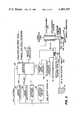
- FIG. 1is a block diagram of an inking system provided in accordance with the invention showing, principally, portions of the system concerned with synchronous positive displacement ink feed through the writing orifice of the pen used in the system;
- FIG. 2is a block diagram showing the pen used in the system described in FIG. 1 as well as components thereof which provide for dynamic pen control based on sensing ink flow through the orifice at the pen tip;
- FIG. 3is a perspective view schematically showing the mechanisim of the inking system illustrated in FIGS. 1 and 2, but with the sensors and actuators associated with the pen for dynamic pen control, which are shown in FIG. 2, removed, to simplify the illustration;
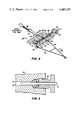
- FIG. 4is an enlarged perspective view showing the interchangeable pen assembly of the system shown in FIG. 3, the view being partially in section, the section being taken along the line 4--4 in FIG. 3;
- FIG. 5is an enlarged fragmentary sectional view of the ram of the positive displacement pumping mechanisim shown in FIG. 4, the section being taken in the general area of the circle indicated in FIG. 4 by the numeral 5, which numeral is contained in a balloon;
- FIG. 6is an enlarged fragmentary sectional view illustrating the valve assembly used in the constant displacement pumping assembly shown in FIGS. 3-5, the section being taken along the line B--B in FIG. 7;
- FIG. 7is a enlarged fragmentary sectional view of the valve assembly shown in FIG. 6, taken along the line A--A in FIG. 6;
- FIG. 8is a view of the valve assembly similiar to the view of FIG. 7, and showing another embodiment thereof;
- FIG. 9is a fragmentary elevational view of the pen, its lift mechanisim and the electro-optical mechanisim associated therewith for sensing the vertical displacement of the pen with respect to the substrate;
- FIG. 10is a schematic view of the vane used in the electro optical assembly shown in FIG. 9, the view being taken along the line A--A in FIG. 9;
- FIG. 11is a schematic view illustrating the pen tip and substrate during initial ink flow from the writing orifice
- FIG. 12is a block diagram illustrating the portions of the inking system operative to control and maintain constant cross-section of line at starts and terminations of lines during the writing thereof;
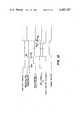
- FIG. 13is a timing diagram illustrating the operation of the portions of the system which are shown in FIG. 12.
- FIG. 1a system is shown which may be used for the development of circuit patterns for thick film hybrid circuits as well as for the computer aided manufacture of such circuits.
- the circuitis printed by writing the pattern on a substrate with standard thick film ink material.
- the pen having the writing orifice and the mechanism for lifting and depressing the pen with respect to the substrateis shown in FIG. 2.
- the substrate 20(FIG. 3) is mounted on an xy translator table 22 which is driven in the x direction by a motor 24 and in the y direction by another motor 26. These motors drive the table to a obtain a desired tangential speed with respect to the pen tip 28 having the writing orifice.
- FIG. 1shows the motor controller 29 for the x motor 24 and the motor controller 30 for the y motor 26. Also shown is an ink pump motor 32 which is controlled by an ink pump motor controller 36.
- the motor controllers, 29, 30, and 36translate command pulses generated by a microprocessor interface controller 38 into signals which drive the motors. The number of pulses determines the displacement produced by the motors and the pulse rate determines the velocity of that displacement.
- the motorsmay be rotary motors with screw drives or other gearing to translate the rotary motion to linear motion. Linear motors may also be used.
- a computerdetermines the pen path topology for the pattern which may consist of rectangles, paths, triangles and arcs for any chosen pen width.
- the computer datais transferred by way of a data bus (suitably the IEEE-488 bus) to the controller 38.
- the computeris equipped with a keyboard 42 into which the operator can input the inking parameters, such as the cross-sectional areas of the lines which are to be written and the writing speed of the pen. Circuit development can be accomplished through the use of the keyboard together with other input devices such as a digitizer/tablet.
- the patternmay be displayed together with other information concerning inking parameters in alpha-numeric form on a graphics display such as a cathode-ray tube display 44.
- a printer with graphics display capability and a plottermay also be tied to the computer as peripheral devices.
- the pattern of the circuitmay be created in the computer aided design operation of the system and stored on a disk or other storage medium 46.
- a floppy disk storage system using a disk drive 48may suitably be connected to the computer as a peripheral device for reading and writing on the disks.
- the computer aided design aspect of the systemmay be carried out with techniques used in the art for computer aided design (CAD) purposes.
- the pen 28is part of an interchangeable pen-pump assembly 50 (See FIG. 3).
- Several assemblieswhich contain a syringe 52, a positive displacement pump mechanisim in a pump block 54, the pen tip 28 and a flexural, A-frame support 56 for the pen tip are provided.
- the pen tipsmay be ceramic, metal or plastic and have orifices of various size to change the line width when the pen tip is changed.
- the ink supplyis from the syringe 52.
- the syringe of each interchangeable assembly 50may be loaded with a different ink material. For example, conductor, dielectric and resistor inks may be loaded into the syringes of the various pen assemblies. Different assemblies may be used for different resistor inks for different resistivities. Inks can be changed readily by interchanging the pen assemblies 50.
- the syringes 52are desirably loaded with ink under vacuum conditions to avoid the inclusions of air or other gas in the ink material. Inasmuch as the syringes 52 are airtight, the pen assemblies 50 can be stored for in a loaded condition for long periods of time without affecting inking quality.
- a pneumatic piston 58provides constant force via a coupling 60 to the plunger 62 of the syringe 52.
- the pump block 54contains a double acting pump mechanisim.
- a passage 64 from the syringegoes to a central valve opening 66 (See FIG. 4).
- a cylindrical valve body 68 in the opening 66provides a four-way valve which alternately directs the ink supply to different pump volumes 70 and 72 defined in a bore 84.
- the double acting pumphas two rams 74 and 76 which displace the pump volumes alternately to pump ink through an outlet passage 78.
- the outlet passage 78is in communication with a tube 80 which has a conduit for ink delivery to the pen 28.
- the other tube 82 of the A-frame 56provides added flexural support for the pen 28.
- the valve 68has two positions 90 degrees apart so that the syringe fills one of the volumes 70 and 72 while one of the rams is 74 or 76 is pumping ink out of the other volume to the pen.
- the ram 76is shown by way of example in FIG. 5. It is a rod which is disposed in the bore 84 in the pump block 54 which provides, in part, the pump volumes.
- a bleed port for air(not shown) may be provided and opened during initial charging of each of the pump volumes with ink. After air is purged the bleed ports are closed. Seal arrangements, including retainer nuts 86 close the pump volumes with which the rams interact. Inasmuch as the ink is in a small closed pump volume 70 or 72, the displacement of the rams 74 or 76 provides a positive volume displacement of the ink from the pump block to the pen.
- a pressure relief valvebe disposed in communication with the passage 78 so as to relieve the pressure in the pump volume which is being pumped in the event of a pen clog. Accordingly during inking, one side of the double acting pump is pumping ink hydraulically from one pump volume, while the other pump volume is being refilled pneumatically. As noted above, ink is delivered to the pen 28 through the pen support tube 80 by positive displacement of the small, closed ink volume. As will be described more fully below this positive displacement is in synchronisim with the table movement and thus with the tangential writing speed of the pen 28.
- the valveis shown is greater detail in FIGS. 6 and 7.
- the valve body 68is a cylinder, preferably made of plastic material such as Delrin which is filled with Teflon particles.
- the passages through the valveare provided by slots 90 and 92 in the valve body which are opposite to each other. These slots 90 and 92 are positioned at 45° with respect to the bores providing the pump volumes 70 and 72 as shown in FIG. 6.
- the pump volume 70may be connected to the syringe delivery passage 64, while the pump volume 72 is connected to the pen delivery passage 78.
- a coupling 94 in the form of a pin 96 passing through the head of the valve body 68is provided for rotating the valve body 90°.
- valve body 68is undercut at 67 to form a step.
- a valve pin retainer plate 69has its forward end in the undercut and holds the valve body in place in the pump block 54 while the allowing the valve body to rotate.
- the valvebe a zero clearance valve to prevent a flow of ink between the pump volumes 70 and 72 at the high pressures generated in the pump block.
- a zero clearancealso assists in preventing the abrasive particles commonly found in thick film ink material from penetrating into the interface between the valve body 68 and the opening 66 in the block 54.
- Seals 98 and 100 held down by seal retainer nutsare disposed on the opposite sides of the passages 64, 70, 72 and 78 in the pump block 54.
- a tapered openingis provided axially in the valve body 68.
- a tapered pin 104is inserted into this opening and spreads the plastic material of the valve body 68 to provide the zero clearance fit.
- a threaded tapered aperture 106 in which a threaded tapered pin 108 is screwedmay be used to provide the adjustment for zero clearance fit.
- Delrin AF filled with Teflonis presently preferred for use as the valve body
- other materialssuch as nylon, Teflon and other phenolic resin plastic materials may be found suitable.
- the pump block 54has bores above and below the central level of the block in which the passages 64 and 78 and the pump volumes 70 and 72 are disposed.
- Rods 110 and 112are located in these bores. These rods 110 and 112 join the two double acting rams 74 and 76 together through coupling blocks 114 and 116 so that they act in concert as a double acting pump.
- a single drive rod 118is used to drive both rams via the couplings 116 and 114 and the tie rods 110 and 112.
- the coupling 116may have a quick disconnection so that the assembly 50 can be interchanged with like assemblies carrying different inks.
- the motor 32(See FIG. 3) turns a drive screw 120 through a preloaded angle contact bearing set 124.
- the rotary motion of the drive screw 120is converted into linear motion of the pump drive shaft 118 by a driven nut, ball slide arrangement 126.
- the position of the pumpis sensed by a linear position transducer 128 which may be a linear potentiometer which is coupled to the linearly moving part of the driven nut ball slide arrangement 126.
- the transducer 128provides an output to the microprocessor interface controller 38 indicating the position (displacement) of the pump.
- the microprocessor interfacehas stored therein data representing the total line length and ink volume necessary to complete the writing the next anticipated line in the pattern.
- an outputis provided to a controller 130 (see FIG. 1) from the microprocessor interface controller.
- This controlleroutputs drive current to an ink valve actuator 132 utilizing opposed solenoids 132 and 134 which reciprocate a rack 136 to drive a spur 138 90° so as to turn the valve body 68.
- the double acting pumpis reversed by signals applied to the ink pump motor 32 via the ink pump motor controller 36, the ink will be pumped from the recharged pump volume and the previously used pump volume will be placed in communication with the syringe for recharging.
- Other actuatorsmay be used for the ink valve, such pneumatically controlled cylinders.
- Synchronous positive displacement pumpingwhich assures controlled, uniform cross-section of ink lines and filled areas of the pattern, independent of selected writing speed, which may be up to 5 inches per second, in this illustrated embodiment of the invention, is obtained by the conjoint control of the ink pump motor controller 36 and the x and y motor controllers 29 and 30.
- a selected writing speedspeed of relative motion of the pen with respect to the moving substrate on the table
- a cross-sectional area of lineof 40 ⁇ 10 -7 square inches.
- the ink motor 32advances approximately 7.8 microinches, in this example, for each pulse which is applied to the ink pump motor controller 36.
- the geometry of the pump volumes 70 and 72are such that a certain volume of ink will be displaced for each 7.8 microinch advance of the ram.
- the pump volume geometryis such that the volume of ink displaced is 1.64 ⁇ 10 -8 cubic inches per pulse applied to the ink pump motor controller.
- the ink volume requirementsare the product or 80 ⁇ 10 -7 cubic inches per second. Since 1.64 ⁇ 10 -8 cubic inches per pulse will delivered by the pump, for an 80 ⁇ 10 -7 cubic inches per second volume requirement to be achieved, the pulse rate must be 487.8 pulses per second.
- a simple algorithm in the interface controller 38provides the necessary pulse rate with the known constant volume displacement of the pump and the desired parameters as inputted from the computer 40 (e.g., line writing speed and cross-section).
- FIG. 2there is shown the pen with its pen tip 28 supported by the flexural support provided by the ink and pen support tubes 56.
- the penis lifted and depressed with respect to the substrate 20 by a electromagnetic coil or solenoid on a core which is of low and preferably zero remnance.
- This coremay be highly purified iron or suitable ferrite ceramic material.
- the actuation forceis applied against a high coercivity magnetic material suitably a samarium cobalt magnet which opposes a non-magnetic spacer at the lower end of the core.
- a control signal from the microprocessorgenerates a pen up/down command to a summing amplifier 140 which drives the electromagnet coil through a driver amplifier 142.
- the energizing current in the coilis increased and the magnet attracted to lift the pen up from the substrate.
- the magnetis lifted into contact with the spacer.
- the current in the coilis reduced gradually to allow the pen tip to descend slowly for a soft landing on the substrate. Then the appropriate inputs are applied to the summing amplifier to establish the necessary magnetic force on the pen tip for dynamic pen control.
- the dynamic pen controlrequires that the vertical position of the pen be sensed continously. This accomplished by an electro-optical sensor using a source of illumination and a light detector.
- the illuminating sourceis suitably a light emitting diode (LED) operative in the infra-red.
- the light detectoris suitably an infra-red responsive photo transistor.
- a vane carried by the flexural support tubes 56intercepts the beam of infra-red illumination. The amount of the beam which is intercepted and the amplitude of the illumination detected by the photo transistor is proportional to the position of the vane and therefore of the vertical displacement of the pen tip 28.
- a square wave driver 144 and a synchronous detector 146are used much in the same manner as in linear analogue optical switches to provide the pen height signal (d).
- This pen height signal (d)is therefore an analogue signal the amplitude of which is directly proportional to the vertical displacement of the pen tip.
- Other displacement sensors, for example with Hall effect devicesmay be used.
- the electro-optical sensoris, however, preferred.
- a vertical position meter 148suitably a zero center meter, calibrated to zero at the center of the dynamic range of the sensor system (including the driver 142, detector and photo transistor, LED arrangement).
- the meterthus enables monitoring visually the vertical position of the pen tip with respect to the center of the dynamic range.
- a microscopetherefore need not be used in the setup adjustments of the writing system.
- the sensoris mounted in a bracket 150 closely adjacent to the electromagnet coil.
- the vane 152is shown mounted on the pen support tubes 56 in a first position at 154 where it is in writing relationship with the substrate and in a second position a 156 where it is lifted to the pen up position; the magnet being in contact with the non-magnetic spacer, as is the condition during loading new substrates and entering of data into the computer.
- the vane 152has an aperture 158. It will be noted that in the writing position at 154, the beam 151 of illumination is partially blocked by the vane. Also in the up position as shown at 156 the beam 151 is also partially blocked, even though the optical sensor is not being used when the pen is in the pen up position. The passage of illumination through the aperture 158 in the pen up position maintains continuity of illuminating energy on the junction of the photo transistor. The temperature of the junction thus is maintained and thermal drift errors in the pen height signal at the beginning of inking when the pen is brought down towards the substrate are minimized.
- FIG. 13also shows the process.
- the pen lift signalwhich has actuated the electromagnet to hold the pen tip up against the non-magnetic spacer drops in amplitude.
- the vertical pen positionthus changes as the pen reaches the substrate.
- SMPa sample of the pen height signal is taken and held as in a sample and hold circuit. This sample and hold circuit is contained in the ink flow sensor 160 (see FIG. 12).
- the flow of inkis started by the application of the pulses which control the ink pumping through the ink pump motor controller 36 (FIG. 1). Pumping of ink is initiated at a pre-pen lift pumping rate which may be different from the pumping rate used during inking of the line which is commanded by the computer so as to maintain uniformity of cross-section of line at different writing speeds. As the ink begins to flow, the viscous forces of the extruding ink, as shown on the right in FIG. 11 causes the pen 28 to rise. The pen height signal, which represents the vertical pen position, increases.
- the ink flow sensor 160(FIG. 12) provides an output when the relative amplitude of the vertical displacement signal reaches the threshold level to trigger a control signal generator 162.
- the trigger point, TRis indicated in FIG. 13 on the vertical pen position diagram.
- the control signal generatorgenerates a pulse, the duration of which may be set under operator control (the operator providing a control signal OP 1 ). This control signal is applied to a pumping rate pulse generator 166 in the interface controller 38 which then increases the pulse rate to the ink pump motor controller 36.
- control signal pulseis the detected by an end of control signal detector 164 which responds to the lagging edge of the control pulse.
- This end of control signalenables the generators 168 and 170 which generate the speed control pulses for the x motor and y motor controllers 28 and 30.
- the table motion pulses which go these controllers 28 and 30then start as shown in FIG. 13.
- a level changer 172is enabled to apply the pen force signal to the pen lift solenoid controller 174.
- This solenoid controlleris provided by circuits in the summing amplifier 140 and by the driver amplifier 142. This enables the pen force signal as inputted from the computer to be applied to the electromagnet coil.
- This pen force signalplays a part in the dynamic control of the vertical displacement of the pen as will be discussed below. Inasmuch as an appropriate pumping rate is selected at line start to overcome ink compression, the line which is written is uniform at line start as well as throughout the writing of the line. The system also accomodates for the energy in the ink upon termination of
- This dynamic pen controlis based on direct ink sensing by the pen tip 28 itself, and provides pen tracking of any substrate camber or cross-over contour without the use of a surface sensing "outrigger" probe at the pen tip.
- the electro-optical sensormonitors vertical pen tip location and exerts appropriate magnetic feedback forces via the summing amplifier 140 and driver amplifier 142 on the pen tip 28 (See FIG. 2).
- the feedback systemelectronically eliminates the spring constant of the pen tip supporting and ink feed structure. It also provides appropriate acceleration assist forces to reduce the inertia of the pen tip.
- a suitable designmay have an operating band width of 200 hz.
- the pen tipdoes not oscillate when the pen force is set to zero.
- the pen tipfloats vertically as though in zero G space, attached to a "rubber" tube support.
- the magnetic feedback forces which drive the pen tipare derived from a sum of currents representing the terms of a second order differential equation that governs the pen dynamics. These currents are generated in the computer so far as the constant pen force -F i in concerned.
- the other currentsare generated from the pen height signal d (by amplifiers and differentiating circuits).
- There is a spring compensationwhich may be generated by a spring compensation circuit 178 which may be an amplifier.
- the mass compensation componentis generated by a circuit 180 which may include a double diferrentiating amplifier.
- the second order differential equation that governs the dynamic pen controlis:
- F his the magnetic lift force
- F iis the lift force from the viscous ink flow which is acting on the pen
- -F iis the pen force in the opposite direction to the lift force
- W Nis the weight equivalent of net effective dynamic pen mass
- kis the spring constant of the pen support and ink delivery tubes structure 56
- Kis a lag constant which is less than but near unity (where 1/(1-K) is the acceleration force gain of the feedback system);
- gis the gravitational acceleration constant;
- dis the vertical pen displacement.
- the first term, kdproduces a force that exactly balances the spring force when the pen is vertically displaced from its equilibrium position.
- the spring compensation circuitry 178can compensate for any non-linearity due to the variable magnet gap between the magnet on the pen tip 28 and the electromagnet coil.
- the second term in the equationprovides the force required for vertical acceleration of the pen tip. This term is only activated when writing over pre-fired lines, since accelerations required for following substrate camber are usually low. This term is effectively a force amplifier term which produces an acceleration force gain identified above. Oscillation will not occur as long as K is less than unity.
- the K valuecan be set by the operator for the amount of acceleration force gain desired. A suitable acceleration range has been found to be plus or minus 2g.
- the spring term, kdcompletely eliminates the spring effect of the pen tip supporting structure.
- the F i termprovides constant, preset downward pen force which remains constant, even when following the vertical contours due to camber of the substrate surface. Typically, for 4 and 8 mil wide lines, the pen force may vary between 50 and 250 milligrams, depending upon the ink material characteristics.
- uniform line cross-sectionsare obtained on start of line by sensing the inception of ink flow, based on the rising pen height crossing a preset relative trigger height above the substrate.
- This outputmay be independent of the rate of pen rise.
- the systemmay be triggered to initiate table movement and increased ink flow at line start by sensing the upward vertical pen velocity at the inception of ink flow. This may be accomplished by differentiating the vertical displacement signal d, and when the differentiated vertical displacement signal corresponds to a preset velocity threshold, an output may be provided to represent the start of ink flow. This output may in turn be used as the start signal to initiate table motion.
- the velocity signalmay be used to monitor vertical pen position deviations due to ink nonuniformity.
- the signalmay be translated into an audible tone giving the operator a very useful monitor of ink quality during inking.
- interface controller 38has a table motion pulse counter 190.
- the end of the table motionis computed as a function of the line length.
- the table motion pulseswhich are provided by the table motor pulse generators 168 and 170 terminate at the end of a line. This is shown in the timing diagram depiction of the table motion pulses.
- acutal termination of table motion and actual termination of the linelags the end of the table motion pulses.
- the expansion of the inkmust be accomodated in order to maintain uniformity of the line cross-section. This is accomplished by means of a delay circuit 192 and another control signal generator 194.
- the delay circuit 192interposes a operator preset delay (OP 2 ) from the termination of the table command pulses until the control signal generator 194 is triggered to produce its control pulse.
- the duration of this control pulsemay also be preset by the operator and is indicated OP 3 .
- the ink pump motor controller 36is reversed by utilizing the pulse as a reverse enable control.
- the pulsesalso apply to the pumping rate pulse generator 166 and increase the pump rate. Accordingly the ink pump is reversed to relieve the ink pressure which was maintained during normal writing. The expansion of the ink upon termination is therefore compensated and line uniformity maintained.
- the ink pump rateis set to zero and pumping stops.
- the leading edge of the pulse from the control signal generator 124also initiates pen lift and removes the pen force.
- the system shown in FIG. 12may be implemented in the microprocesser controller by appropriate programming.
Landscapes
- Engineering & Computer Science (AREA)
- Manufacturing & Machinery (AREA)
- Microelectronics & Electronic Packaging (AREA)
- Physics & Mathematics (AREA)
- General Physics & Mathematics (AREA)
- Particle Formation And Scattering Control In Inkjet Printers (AREA)
- Manufacturing Of Printed Wiring (AREA)
Abstract
Description
F.sub.h =kd+KW.sub.N (1/g)d-F.sub.i
Claims (36)
F.sub.h =kd+KW.sub.N (1/g)d-F.sub.i,
F.sub.h =kd+KW.sub.N (1/g)d-F.sub.i,
Priority Applications (6)
| Application Number | Priority Date | Filing Date | Title |
|---|---|---|---|
| US06/436,862US4485387A (en) | 1982-10-26 | 1982-10-26 | Inking system for producing circuit patterns |
| JP58503718AJPS60500011A (en) | 1982-10-26 | 1983-10-21 | Ink coating device that forms circuit patterns |
| EP19830903728EP0126742A4 (en) | 1982-10-26 | 1983-10-21 | Inking system for producing circuit patterns. |
| PCT/US1983/001669WO1984001825A1 (en) | 1982-10-26 | 1983-10-21 | Inking system for producing circuit patterns |
| AU22638/83AAU2263883A (en) | 1982-10-26 | 1983-10-21 | Inking system for producing circuit patterns |
| CA000439625ACA1205569A (en) | 1982-10-26 | 1983-10-25 | Inking system for producing circuit patterns |
Applications Claiming Priority (1)
| Application Number | Priority Date | Filing Date | Title |
|---|---|---|---|
| US06/436,862US4485387A (en) | 1982-10-26 | 1982-10-26 | Inking system for producing circuit patterns |
Publications (1)
| Publication Number | Publication Date |
|---|---|
| US4485387Atrue US4485387A (en) | 1984-11-27 |
Family
ID=23734130
Family Applications (1)
| Application Number | Title | Priority Date | Filing Date |
|---|---|---|---|
| US06/436,862Expired - LifetimeUS4485387A (en) | 1982-10-26 | 1982-10-26 | Inking system for producing circuit patterns |
Country Status (5)
| Country | Link |
|---|---|
| US (1) | US4485387A (en) |
| EP (1) | EP0126742A4 (en) |
| JP (1) | JPS60500011A (en) |
| CA (1) | CA1205569A (en) |
| WO (1) | WO1984001825A1 (en) |
Cited By (83)
| Publication number | Priority date | Publication date | Assignee | Title |
|---|---|---|---|---|
| US4661368A (en)* | 1985-09-18 | 1987-04-28 | Universal Instruments Corporation | Surface locating and dispensed dosage sensing method and apparatus |
| US4664945A (en)* | 1983-08-19 | 1987-05-12 | Matsushita Electric Industrial Co., Ltd. | Method of forming thick film circuits |
| US4692351A (en)* | 1984-04-16 | 1987-09-08 | Matsushita Electric Industrial Co., Ltd. | Method and apparatus for drawing a thick film circuit |
| US4694776A (en)* | 1984-06-21 | 1987-09-22 | Co-Ordinate Technology Ltd. | Step and repeat apparatus |
| US4720798A (en)* | 1985-04-16 | 1988-01-19 | Protocad, Inc. | Process for use in rapidly producing printed circuit boards using a computer controlled plotter |
| US4762578A (en)* | 1987-04-28 | 1988-08-09 | Universal Instruments Corporation | Non-contact sensing and controlling of spacing between a depositing tip and each selected depositing location on a substrate |
| US4786576A (en)* | 1984-09-27 | 1988-11-22 | Olin Hunt Specialty Products, Inc. | Method of high resolution of electrostatic transfer of a high density image to a nonporous and nonabsorbent conductive substrate |
| US4823277A (en)* | 1985-04-16 | 1989-04-18 | Protocad, Inc. | Forming plated through holes in a printed circuit board by using a computer controlled plotter |
| US4848606A (en)* | 1986-07-31 | 1989-07-18 | Tokyo Juki Industrial Co., Ltd. | Apparatus for dispensing a predetermined volume of paste-like fluid |
| US4926348A (en)* | 1986-12-05 | 1990-05-15 | Royal Melbourne Institute Of Technology Limited | Plotting apparatus using a light source moved on a photosensitive surface |
| US4983429A (en)* | 1987-07-13 | 1991-01-08 | Fuji Photo Film Co., Ltd. | Process for producing cells for liquid crystal display devices |
| US5151377A (en)* | 1991-03-07 | 1992-09-29 | Mobil Solar Energy Corporation | Method for forming contacts |
| US5498289A (en)* | 1992-02-24 | 1996-03-12 | Mitsubishi Denki Kabushiki Kaisha | Apparatus for applying narrow metal electrode |
| US5521576A (en)* | 1993-10-06 | 1996-05-28 | Collins; Franklyn M. | Fine-line thick film resistors and resistor networks and method of making same |
| WO1997032320A1 (en)* | 1996-02-28 | 1997-09-04 | Sigma-Netics, Inc. | Improved strain gauge and method of manufacture |
| US5956050A (en)* | 1997-07-28 | 1999-09-21 | Eastman Kodak Company | Microfluidic printing without image reversal |
| US5973708A (en)* | 1997-10-02 | 1999-10-26 | Eastman Kodak Company | Air isolation of ink segments by microfluidic printing |
| US5973296A (en)* | 1998-10-20 | 1999-10-26 | Watlow Electric Manufacturing Company | Thick film heater for injection mold runner nozzle |
| US5986678A (en)* | 1997-06-03 | 1999-11-16 | Eastman Kodak Company | Microfluidic printing on receiver |
| EP0979028A1 (en) | 1998-08-05 | 2000-02-09 | ESEC Management SA | Device for dosing a very viscous liquid |
| US6055004A (en)* | 1997-07-31 | 2000-04-25 | Eastman Kodak Company | Microfluidic printing array valve |
| US6057864A (en)* | 1997-06-03 | 2000-05-02 | Eastman Kodak Company | Image producing apparatus for uniform microfluidic printing |
| US6132809A (en)* | 1997-01-16 | 2000-10-17 | Precision Valve & Automation, Inc. | Conformal coating using multiple applications |
| WO2001014069A1 (en)* | 1999-08-24 | 2001-03-01 | Loctite (R & D) Limited | Device and method for dispensing fluid materials |
| US6305923B1 (en) | 1998-06-12 | 2001-10-23 | Husky Injection Molding Systems Ltd. | Molding system using film heaters and/or sensors |
| US6383571B1 (en) | 1998-12-17 | 2002-05-07 | Guardian Industries Corp. | Device and method for coating a flat substrate |
| US6394784B1 (en) | 2000-03-08 | 2002-05-28 | Mold-Masters Limited | Compact cartridge hot runner nozzle |
| WO2002047447A1 (en)* | 2000-12-09 | 2002-06-13 | Xaar Technology Limited | Method of forming electrically conductive elements and patterns of such elements |
| WO2003011607A1 (en) | 2001-07-31 | 2003-02-13 | Pilkington North America, Inc. | Method for placing indicia on substrates |
| US20030048314A1 (en)* | 1998-09-30 | 2003-03-13 | Optomec Design Company | Direct write TM system |
| US20030185971A1 (en)* | 2002-03-26 | 2003-10-02 | Saksa Thomas A. | Methods for ink-jet printing circuitry |
| US20030228124A1 (en)* | 1998-09-30 | 2003-12-11 | Renn Michael J. | Apparatuses and method for maskless mesoscale material deposition |
| US20040018413A1 (en)* | 2002-07-24 | 2004-01-29 | Trabold Thomas A. | PEM fuel cell stack without gas diffusion media |
| US20040115543A1 (en)* | 2002-12-16 | 2004-06-17 | Xerox Corporation | Imaging member |
| US20040179808A1 (en)* | 1998-09-30 | 2004-09-16 | Optomec Design Company | Particle guidance system |
| US20040197493A1 (en)* | 1998-09-30 | 2004-10-07 | Optomec Design Company | Apparatus, methods and precision spray processes for direct write and maskless mesoscale material deposition |
| US20040238202A1 (en)* | 2003-06-02 | 2004-12-02 | Ohmcraft Inc. | Method of making an inductor with written wire and an inductor made therefrom |
| US20040253365A1 (en)* | 2001-08-23 | 2004-12-16 | Warren William L. | Architecture tool and methods of use |
| US20050095494A1 (en)* | 2003-11-03 | 2005-05-05 | Fuss Robert L. | Variable catalyst loading based on flow field geometry |
| US20050129383A1 (en)* | 1998-09-30 | 2005-06-16 | Optomec Design Company | Laser processing for heat-sensitive mesoscale deposition |
| US20050136639A1 (en)* | 2003-12-18 | 2005-06-23 | The Regents Of The University Of California | Pin-deposition of conductive inks for microelectrodes and contact via filling |
| US20050156991A1 (en)* | 1998-09-30 | 2005-07-21 | Optomec Design Company | Maskless direct write of copper using an annular aerosol jet |
| US20050233199A1 (en)* | 2004-04-05 | 2005-10-20 | Xingwu Wang | Hydrogen storage apparatus comprised of halloysite |
| US20050234289A1 (en)* | 2003-06-26 | 2005-10-20 | Anstadt Mark P | Therapeutic agent delivery apparatus with direct mechanical ventricular assistance capability |
| US20060002986A1 (en)* | 2004-06-09 | 2006-01-05 | Smithkline Beecham Corporation | Pharmaceutical product |
| US20060016830A1 (en)* | 2004-06-09 | 2006-01-26 | Smithkline Beecham Corporation | Apparatus and method for pharmaceutical production |
| US20060076354A1 (en)* | 2004-10-07 | 2006-04-13 | Lanzafame John F | Hydrogen storage apparatus |
| US20060163160A1 (en)* | 2005-01-25 | 2006-07-27 | Weiner Michael L | Halloysite microtubule processes, structures, and compositions |
| US20060166810A1 (en)* | 2005-01-25 | 2006-07-27 | Gunderman Robert D | Ultracapacitors comprised of mineral microtubules |
| US20060167334A1 (en)* | 2003-06-26 | 2006-07-27 | Anstadt Mark P | Method and apparatus for direct mechanical ventricular actuation with favorable conditioning and minimal heart stress |
| US20060175321A1 (en)* | 2004-03-10 | 2006-08-10 | Watlow Electric Manufacturing Company | Methods of forming a variable watt density layered heater |
| US7091412B2 (en) | 2002-03-04 | 2006-08-15 | Nanoset, Llc | Magnetically shielded assembly |
| US7162302B2 (en) | 2002-03-04 | 2007-01-09 | Nanoset Llc | Magnetically shielded assembly |
| US20070152896A1 (en)* | 2005-12-29 | 2007-07-05 | Robert Schwenke | Antenna for plastic window panel |
| US7241131B1 (en) | 2000-06-19 | 2007-07-10 | Husky Injection Molding Systems Ltd. | Thick film heater apparatus |
| US20070233270A1 (en)* | 2006-03-29 | 2007-10-04 | Boston Scientific Scimed, Inc. | Stent with overlap and high expansion |
| US20080138927A1 (en)* | 2004-03-11 | 2008-06-12 | The University Of Vermont And State Agricultural College | Systems and Methods for Fabricating Crystalline Thin Structures Using Meniscal Growth Techniques |
| CN100424531C (en)* | 2006-08-07 | 2008-10-08 | 华中科技大学 | Special direct-writing device for preparing polymer optical waveguide |
| US7553512B2 (en) | 2001-11-02 | 2009-06-30 | Cabot Corporation | Method for fabricating an inorganic resistor |
| WO2009151981A1 (en)* | 2008-06-11 | 2009-12-17 | Boston Scientific Scimed, Inc. | Precision pen height control for micro-scale direct writing technology |
| US20090319026A1 (en)* | 2008-06-20 | 2009-12-24 | Boston Scientific Scimed, Inc. | Composite Stent with Reservoirs for Drug Delivery and Methods of Manufacturing |
| US20100055299A1 (en)* | 2008-09-02 | 2010-03-04 | Nscrypt, Inc. | Dispensing patterns including lines and dots at high speeds |
| US7674671B2 (en) | 2004-12-13 | 2010-03-09 | Optomec Design Company | Aerodynamic jetting of aerosolized fluids for fabrication of passive structures |
| US20100126980A1 (en)* | 2008-11-24 | 2010-05-27 | Jeremy Fetvedt | Direct vessel heating for dissolution testing |
| WO2010080822A1 (en)* | 2009-01-06 | 2010-07-15 | 1366 Technologies Inc. | Dispensing liquid containing material to patterned surfaces using a dispensing tube |
| US20100207291A1 (en)* | 2009-02-13 | 2010-08-19 | Boston Scientific Scimed, Inc. | Method of Making a Tubular Member |
| US7938341B2 (en) | 2004-12-13 | 2011-05-10 | Optomec Design Company | Miniature aerosol jet and aerosol jet array |
| US7938079B2 (en) | 1998-09-30 | 2011-05-10 | Optomec Design Company | Annular aerosol jet deposition using an extended nozzle |
| US8101244B2 (en) | 2004-06-09 | 2012-01-24 | Smithkline Beecham Corporation | Apparatus and method for producing or processing a product or sample |
| US8110247B2 (en) | 1998-09-30 | 2012-02-07 | Optomec Design Company | Laser processing for heat-sensitive mesoscale deposition of oxygen-sensitive materials |
| US20120226373A1 (en)* | 2011-03-03 | 2012-09-06 | GM Global Technology Operations LLC | Multi-mode ultrasonic welding control and optimization |
| US8272579B2 (en) | 2007-08-30 | 2012-09-25 | Optomec, Inc. | Mechanically integrated and closely coupled print head and mist source |
| CN103302975A (en)* | 2012-03-16 | 2013-09-18 | 富士施乐株式会社 | Intermediate transfer belt of image recording device, method for making the same, and image recording device |
| US20140264021A1 (en)* | 2013-03-18 | 2014-09-18 | Smiths Detection Montreal Inc. | Ion mobility spectrometry (ims) device with charged material transportation chamber |
| US8887658B2 (en) | 2007-10-09 | 2014-11-18 | Optomec, Inc. | Multiple sheath multiple capillary aerosol jet |
| WO2015010680A3 (en)* | 2013-07-22 | 2015-03-26 | Zs-Handling Gmbh | Device for treating or machining a surface |
| US9192054B2 (en) | 2007-08-31 | 2015-11-17 | Optomec, Inc. | Apparatus for anisotropic focusing |
| US10632746B2 (en) | 2017-11-13 | 2020-04-28 | Optomec, Inc. | Shuttering of aerosol streams |
| US10994473B2 (en) | 2015-02-10 | 2021-05-04 | Optomec, Inc. | Fabrication of three dimensional structures by in-flight curing of aerosols |
| CN113318919A (en)* | 2021-06-30 | 2021-08-31 | 成都飞机工业(集团)有限责任公司 | Automatic coating process of robot on airplane part sealant |
| US11749428B2 (en)* | 2020-10-16 | 2023-09-05 | Abb Schweiz Ag | Electrically resistive devices, including voltage dividers |
| US11969947B2 (en) | 2020-11-06 | 2024-04-30 | Abb Schweiz Ag | Technologies for non-contact displacement control |
| US12172444B2 (en) | 2021-04-29 | 2024-12-24 | Optomec, Inc. | High reliability sheathed transport path for aerosol jet devices |
Families Citing this family (3)
| Publication number | Priority date | Publication date | Assignee | Title |
|---|---|---|---|---|
| FR2579856B1 (en)* | 1985-03-28 | 1988-09-16 | Lignes Telegraph Telephon | WRITING DEVICE AND METHOD FOR PRODUCING ELECTRICAL CIRCUITS |
| GB8728865D0 (en)* | 1987-12-10 | 1988-01-27 | Versatronics Ltd | Apparatus & method for manufacture of printed circuit board & prototypes |
| US7351290B2 (en) | 2003-07-17 | 2008-04-01 | General Electric Company | Robotic pen |
Citations (4)
| Publication number | Priority date | Publication date | Assignee | Title |
|---|---|---|---|---|
| US3820121A (en)* | 1972-10-13 | 1974-06-25 | Gerber Scientific Instr Co | Apparatus for expressing a writing fluid |
| US3864695A (en)* | 1972-09-25 | 1975-02-04 | Asahi Optical Co Ltd | Pen having vertical movement control |
| US3961599A (en)* | 1971-08-12 | 1976-06-08 | Air Products And Chemicals, Inc. | Apparatus for making miniature layer resistors on insulating chips by digital controls |
| US4291642A (en)* | 1979-12-26 | 1981-09-29 | Rca Corporation | Nozzle for dispensing viscous fluid |
Family Cites Families (2)
| Publication number | Priority date | Publication date | Assignee | Title |
|---|---|---|---|---|
| JPS56164598A (en)* | 1980-05-21 | 1981-12-17 | Fujitsu Ltd | Automatic miniature circuit forming device |
| JPS5710289A (en)* | 1980-06-20 | 1982-01-19 | Suwa Seikosha Kk | Electronic component |
- 1982
- 1982-10-26USUS06/436,862patent/US4485387A/ennot_activeExpired - Lifetime
- 1983
- 1983-10-21JPJP58503718Apatent/JPS60500011A/enactivePending
- 1983-10-21EPEP19830903728patent/EP0126742A4/ennot_activeCeased
- 1983-10-21WOPCT/US1983/001669patent/WO1984001825A1/ennot_activeApplication Discontinuation
- 1983-10-25CACA000439625Apatent/CA1205569A/ennot_activeExpired
Patent Citations (4)
| Publication number | Priority date | Publication date | Assignee | Title |
|---|---|---|---|---|
| US3961599A (en)* | 1971-08-12 | 1976-06-08 | Air Products And Chemicals, Inc. | Apparatus for making miniature layer resistors on insulating chips by digital controls |
| US3864695A (en)* | 1972-09-25 | 1975-02-04 | Asahi Optical Co Ltd | Pen having vertical movement control |
| US3820121A (en)* | 1972-10-13 | 1974-06-25 | Gerber Scientific Instr Co | Apparatus for expressing a writing fluid |
| US4291642A (en)* | 1979-12-26 | 1981-09-29 | Rca Corporation | Nozzle for dispensing viscous fluid |
Non-Patent Citations (6)
| Title |
|---|
| Reverse Engineering Corp, "Thick Film Writing Systems", A Product Bulletin. |
| Reverse Engineering Corp, Thick Film Writing Systems , A Product Bulletin.* |
| Shankin, Morris, Write It, Don t Screen It; Int. Symp. on Microelectronics, ISHM, 1978.* |
| Shankin, Morris, Write It, Don't Screen It; Int. Symp. on _Microelectronics, ISHM, 1978. |
| Zarnow, David F., An Introduction to the Navy Mfg. Technology Program For _Computerized Thick Film Printing; Int. Symp. on Microelectronics, ISHM, 1978. |
| Zarnow, David F., An Introduction to the Navy Mfg. Technology Program For Computerized Thick Film Printing; Int. Symp. on Microelectronics, ISHM, 1978.* |
Cited By (158)
| Publication number | Priority date | Publication date | Assignee | Title |
|---|---|---|---|---|
| US4664945A (en)* | 1983-08-19 | 1987-05-12 | Matsushita Electric Industrial Co., Ltd. | Method of forming thick film circuits |
| US4692351A (en)* | 1984-04-16 | 1987-09-08 | Matsushita Electric Industrial Co., Ltd. | Method and apparatus for drawing a thick film circuit |
| US4694776A (en)* | 1984-06-21 | 1987-09-22 | Co-Ordinate Technology Ltd. | Step and repeat apparatus |
| US4786576A (en)* | 1984-09-27 | 1988-11-22 | Olin Hunt Specialty Products, Inc. | Method of high resolution of electrostatic transfer of a high density image to a nonporous and nonabsorbent conductive substrate |
| US4879184A (en)* | 1984-09-27 | 1989-11-07 | Olin Hunt Specialty Products Inc. | Method of high resolution of electrostatic transfer of a high density image to a receiving substrate |
| US4720798A (en)* | 1985-04-16 | 1988-01-19 | Protocad, Inc. | Process for use in rapidly producing printed circuit boards using a computer controlled plotter |
| US4823277A (en)* | 1985-04-16 | 1989-04-18 | Protocad, Inc. | Forming plated through holes in a printed circuit board by using a computer controlled plotter |
| EP0216601A3 (en)* | 1985-09-18 | 1987-10-07 | Universal Instruments Corporation | Surface locating and dispensed dosage sensing method and apparatus |
| US4661368A (en)* | 1985-09-18 | 1987-04-28 | Universal Instruments Corporation | Surface locating and dispensed dosage sensing method and apparatus |
| US4848606A (en)* | 1986-07-31 | 1989-07-18 | Tokyo Juki Industrial Co., Ltd. | Apparatus for dispensing a predetermined volume of paste-like fluid |
| US4926348A (en)* | 1986-12-05 | 1990-05-15 | Royal Melbourne Institute Of Technology Limited | Plotting apparatus using a light source moved on a photosensitive surface |
| US4762578A (en)* | 1987-04-28 | 1988-08-09 | Universal Instruments Corporation | Non-contact sensing and controlling of spacing between a depositing tip and each selected depositing location on a substrate |
| US4983429A (en)* | 1987-07-13 | 1991-01-08 | Fuji Photo Film Co., Ltd. | Process for producing cells for liquid crystal display devices |
| US5151377A (en)* | 1991-03-07 | 1992-09-29 | Mobil Solar Energy Corporation | Method for forming contacts |
| US5498289A (en)* | 1992-02-24 | 1996-03-12 | Mitsubishi Denki Kabushiki Kaisha | Apparatus for applying narrow metal electrode |
| US5521576A (en)* | 1993-10-06 | 1996-05-28 | Collins; Franklyn M. | Fine-line thick film resistors and resistor networks and method of making same |
| US5548268A (en)* | 1993-10-06 | 1996-08-20 | Collins; Franklyn M. | Fine-line thick film resistors and resistor networks and method of making same |
| US5861558A (en)* | 1996-02-28 | 1999-01-19 | Sigma-Netics, Inc. | Strain gauge and method of manufacture |
| WO1997032320A1 (en)* | 1996-02-28 | 1997-09-04 | Sigma-Netics, Inc. | Improved strain gauge and method of manufacture |
| US6447847B1 (en) | 1997-01-16 | 2002-09-10 | Precision Valve & Automation, Inc. | Conformal coating using multiple applicators |
| US6132809A (en)* | 1997-01-16 | 2000-10-17 | Precision Valve & Automation, Inc. | Conformal coating using multiple applications |
| US5986678A (en)* | 1997-06-03 | 1999-11-16 | Eastman Kodak Company | Microfluidic printing on receiver |
| US6057864A (en)* | 1997-06-03 | 2000-05-02 | Eastman Kodak Company | Image producing apparatus for uniform microfluidic printing |
| US5956050A (en)* | 1997-07-28 | 1999-09-21 | Eastman Kodak Company | Microfluidic printing without image reversal |
| US6055004A (en)* | 1997-07-31 | 2000-04-25 | Eastman Kodak Company | Microfluidic printing array valve |
| US5973708A (en)* | 1997-10-02 | 1999-10-26 | Eastman Kodak Company | Air isolation of ink segments by microfluidic printing |
| US6305923B1 (en) | 1998-06-12 | 2001-10-23 | Husky Injection Molding Systems Ltd. | Molding system using film heaters and/or sensors |
| US7071449B2 (en) | 1998-06-12 | 2006-07-04 | Husky Injection Molding Systems Ltd. | Molding system with integrated film heaters and sensors |
| US6575729B2 (en) | 1998-06-12 | 2003-06-10 | Husky Injection Molding Systems Ltd. | Molding system with integrated film heaters and sensors |
| US6341954B1 (en) | 1998-06-12 | 2002-01-29 | Husky Injection Molding Systems Ltd. | Molding system using film heaters and/or sensors |
| US7029260B2 (en) | 1998-06-12 | 2006-04-18 | Husky Injection Molding Systems Ltd. | Molding apparatus having a film heater |
| US20050129801A1 (en)* | 1998-06-12 | 2005-06-16 | Harold Godwin | Film heater apparatus and method for molding devices |
| US20040222209A1 (en)* | 1998-06-12 | 2004-11-11 | Harold Godwin | Molding system with integrated film heaters and sensors |
| US6764297B2 (en) | 1998-06-12 | 2004-07-20 | Husky Injection Molding Systems Ltd. | Molding system with integrated film heaters and sensors |
| US20030206991A1 (en)* | 1998-06-12 | 2003-11-06 | Harold Godwin | Molding system with integrated film heaters and sensors |
| EP0979028A1 (en) | 1998-08-05 | 2000-02-09 | ESEC Management SA | Device for dosing a very viscous liquid |
| US20040197493A1 (en)* | 1998-09-30 | 2004-10-07 | Optomec Design Company | Apparatus, methods and precision spray processes for direct write and maskless mesoscale material deposition |
| US20040179808A1 (en)* | 1998-09-30 | 2004-09-16 | Optomec Design Company | Particle guidance system |
| US20030048314A1 (en)* | 1998-09-30 | 2003-03-13 | Optomec Design Company | Direct write TM system |
| US7045015B2 (en) | 1998-09-30 | 2006-05-16 | Optomec Design Company | Apparatuses and method for maskless mesoscale material deposition |
| US7938079B2 (en) | 1998-09-30 | 2011-05-10 | Optomec Design Company | Annular aerosol jet deposition using an extended nozzle |
| US8455051B2 (en) | 1998-09-30 | 2013-06-04 | Optomec, Inc. | Apparatuses and methods for maskless mesoscale material deposition |
| US7485345B2 (en) | 1998-09-30 | 2009-02-03 | Optomec Design Company | Apparatuses and methods for maskless mesoscale material deposition |
| US7108894B2 (en) | 1998-09-30 | 2006-09-19 | Optomec Design Company | Direct Write™ System |
| US20030228124A1 (en)* | 1998-09-30 | 2003-12-11 | Renn Michael J. | Apparatuses and method for maskless mesoscale material deposition |
| US7987813B2 (en) | 1998-09-30 | 2011-08-02 | Optomec, Inc. | Apparatuses and methods for maskless mesoscale material deposition |
| US20050163917A1 (en)* | 1998-09-30 | 2005-07-28 | Optomec Design Company | Direct writeTM system |
| US20050156991A1 (en)* | 1998-09-30 | 2005-07-21 | Optomec Design Company | Maskless direct write of copper using an annular aerosol jet |
| US20050129383A1 (en)* | 1998-09-30 | 2005-06-16 | Optomec Design Company | Laser processing for heat-sensitive mesoscale deposition |
| US20050046664A1 (en)* | 1998-09-30 | 2005-03-03 | Optomec Design Company | Direct writeTM system |
| US7270844B2 (en) | 1998-09-30 | 2007-09-18 | Optomec Design Company | Direct write™ system |
| US7658163B2 (en) | 1998-09-30 | 2010-02-09 | Optomec Design Company | Direct write# system |
| US7294366B2 (en) | 1998-09-30 | 2007-11-13 | Optomec Design Company | Laser processing for heat-sensitive mesoscale deposition |
| US8110247B2 (en) | 1998-09-30 | 2012-02-07 | Optomec Design Company | Laser processing for heat-sensitive mesoscale deposition of oxygen-sensitive materials |
| US5973296A (en)* | 1998-10-20 | 1999-10-26 | Watlow Electric Manufacturing Company | Thick film heater for injection mold runner nozzle |
| US6383571B1 (en) | 1998-12-17 | 2002-05-07 | Guardian Industries Corp. | Device and method for coating a flat substrate |
| WO2001014069A1 (en)* | 1999-08-24 | 2001-03-01 | Loctite (R & D) Limited | Device and method for dispensing fluid materials |
| US6491974B1 (en) | 1999-08-24 | 2002-12-10 | Loctite (R&D) Limited | Device and method for dispensing fluid materials |
| US20040037913A1 (en)* | 2000-03-08 | 2004-02-26 | Mold-Masters Limited | Hot runner nozzle with interlaced heater and sensor |
| US7438551B2 (en) | 2000-03-08 | 2008-10-21 | Mold-Masters (2007) Limited | Compact cartridge hot runner nozzle |
| US20070154588A1 (en)* | 2000-03-08 | 2007-07-05 | Mold-Masters Limited | Compact Cartridge Hot Runner Nozzle |
| US7413432B2 (en) | 2000-03-08 | 2008-08-19 | Mold-Masters (2007) Limited | Compact cartridge hot runner nozzle |
| US6394784B1 (en) | 2000-03-08 | 2002-05-28 | Mold-Masters Limited | Compact cartridge hot runner nozzle |
| US20070148279A1 (en)* | 2000-03-08 | 2007-06-28 | Mold-Masters Limited | Compact Cartridge Hot Runner Nozzle |
| US20060292256A1 (en)* | 2000-03-08 | 2006-12-28 | Gellert Jobst U | Hot runner nozzle with removable sleeve |
| US6761557B2 (en) | 2000-03-08 | 2004-07-13 | Mold-Masters Limited | Compact cartridge hot runner nozzle |
| US7377768B2 (en) | 2000-03-08 | 2008-05-27 | Mold-Masters (2007) Limited | Hot runner nozzle with removable sleeve |
| US7108502B2 (en) | 2000-03-08 | 2006-09-19 | Mold-Masters Limited | Hot runner nozzle with interlaced heater and sensor |
| US20030228390A1 (en)* | 2000-03-08 | 2003-12-11 | Mold-Masters Limited | Compact cartridge hot runner nozzle and method of making |
| US6638053B2 (en) | 2000-03-08 | 2003-10-28 | Mold-Masters Limited | Compact cartridge hot runner nozzle |
| US6561789B2 (en) | 2000-03-08 | 2003-05-13 | Mold-Masters Limited | Compact cartridge hot runner nozzle |
| US7241131B1 (en) | 2000-06-19 | 2007-07-10 | Husky Injection Molding Systems Ltd. | Thick film heater apparatus |
| WO2002047447A1 (en)* | 2000-12-09 | 2002-06-13 | Xaar Technology Limited | Method of forming electrically conductive elements and patterns of such elements |
| GB2385561A (en)* | 2000-12-09 | 2003-08-27 | Xaar Technology Ltd | Method of printing using a droplet deposition apparatus |
| US20040160465A1 (en)* | 2000-12-09 | 2004-08-19 | Hugh Baker-Smith | Method of printing using a droplet deposition apparatus |
| GB2385561B (en)* | 2000-12-09 | 2004-07-21 | Xaar Technology Ltd | Method of forming electrically conductive elements and patterns of such elements |
| US6701835B2 (en)* | 2001-07-31 | 2004-03-09 | Pilkington North America, Inc. | Method for placing indicia on substrates |
| WO2003011607A1 (en) | 2001-07-31 | 2003-02-13 | Pilkington North America, Inc. | Method for placing indicia on substrates |
| US7857756B2 (en) | 2001-08-23 | 2010-12-28 | Sciperio, Inc. | Architecture tool and methods of use |
| US6986739B2 (en) | 2001-08-23 | 2006-01-17 | Sciperio, Inc. | Architecture tool and methods of use |
| US20040253365A1 (en)* | 2001-08-23 | 2004-12-16 | Warren William L. | Architecture tool and methods of use |
| US7553512B2 (en) | 2001-11-02 | 2009-06-30 | Cabot Corporation | Method for fabricating an inorganic resistor |
| US7162302B2 (en) | 2002-03-04 | 2007-01-09 | Nanoset Llc | Magnetically shielded assembly |
| US7091412B2 (en) | 2002-03-04 | 2006-08-15 | Nanoset, Llc | Magnetically shielded assembly |
| US7442408B2 (en)* | 2002-03-26 | 2008-10-28 | Hewlett-Packard Development Company, L.P. | Methods for ink-jet printing circuitry |
| US20030185971A1 (en)* | 2002-03-26 | 2003-10-02 | Saksa Thomas A. | Methods for ink-jet printing circuitry |
| US6916573B2 (en) | 2002-07-24 | 2005-07-12 | General Motors Corporation | PEM fuel cell stack without gas diffusion media |
| US20040018413A1 (en)* | 2002-07-24 | 2004-01-29 | Trabold Thomas A. | PEM fuel cell stack without gas diffusion media |
| US20040115543A1 (en)* | 2002-12-16 | 2004-06-17 | Xerox Corporation | Imaging member |
| US6797445B2 (en) | 2002-12-16 | 2004-09-28 | Xerox Corporation | Imaging member |
| US20040238202A1 (en)* | 2003-06-02 | 2004-12-02 | Ohmcraft Inc. | Method of making an inductor with written wire and an inductor made therefrom |
| US20050234289A1 (en)* | 2003-06-26 | 2005-10-20 | Anstadt Mark P | Therapeutic agent delivery apparatus with direct mechanical ventricular assistance capability |
| US7494459B2 (en) | 2003-06-26 | 2009-02-24 | Biophan Technologies, Inc. | Sensor-equipped and algorithm-controlled direct mechanical ventricular assist device |
| US20060167334A1 (en)* | 2003-06-26 | 2006-07-27 | Anstadt Mark P | Method and apparatus for direct mechanical ventricular actuation with favorable conditioning and minimal heart stress |
| US20050095494A1 (en)* | 2003-11-03 | 2005-05-05 | Fuss Robert L. | Variable catalyst loading based on flow field geometry |
| US7036220B2 (en)* | 2003-12-18 | 2006-05-02 | The Regents Of The University Of California | Pin-deposition of conductive inks for microelectrodes and contact via filling |
| US20050136639A1 (en)* | 2003-12-18 | 2005-06-23 | The Regents Of The University Of California | Pin-deposition of conductive inks for microelectrodes and contact via filling |
| US8008607B2 (en)* | 2004-03-10 | 2011-08-30 | Watlow Electric Manufacturing Company | Methods of forming a variable watt density layered heater |
| US20070023419A1 (en)* | 2004-03-10 | 2007-02-01 | Watlow Electric Manufacturing Company | Variable watt density layered heater |
| US20060175321A1 (en)* | 2004-03-10 | 2006-08-10 | Watlow Electric Manufacturing Company | Methods of forming a variable watt density layered heater |
| US20080138927A1 (en)* | 2004-03-11 | 2008-06-12 | The University Of Vermont And State Agricultural College | Systems and Methods for Fabricating Crystalline Thin Structures Using Meniscal Growth Techniques |
| US7425232B2 (en) | 2004-04-05 | 2008-09-16 | Naturalnano Research, Inc. | Hydrogen storage apparatus comprised of halloysite |
| US20050233199A1 (en)* | 2004-04-05 | 2005-10-20 | Xingwu Wang | Hydrogen storage apparatus comprised of halloysite |
| US8101244B2 (en) | 2004-06-09 | 2012-01-24 | Smithkline Beecham Corporation | Apparatus and method for producing or processing a product or sample |
| US8252234B2 (en) | 2004-06-09 | 2012-08-28 | Smithkline Beecham Corporation | Apparatus for producing a pharmaceutical product |
| US20060002986A1 (en)* | 2004-06-09 | 2006-01-05 | Smithkline Beecham Corporation | Pharmaceutical product |
| US20060016830A1 (en)* | 2004-06-09 | 2006-01-26 | Smithkline Beecham Corporation | Apparatus and method for pharmaceutical production |
| US8122849B2 (en) | 2004-06-09 | 2012-02-28 | Smithkline Beecham Corporation | Apparatus and method for producing a pharmaceutical product |
| US20060076354A1 (en)* | 2004-10-07 | 2006-04-13 | Lanzafame John F | Hydrogen storage apparatus |
| US7938341B2 (en) | 2004-12-13 | 2011-05-10 | Optomec Design Company | Miniature aerosol jet and aerosol jet array |
| US8132744B2 (en) | 2004-12-13 | 2012-03-13 | Optomec, Inc. | Miniature aerosol jet and aerosol jet array |
| US9607889B2 (en) | 2004-12-13 | 2017-03-28 | Optomec, Inc. | Forming structures using aerosol jet® deposition |
| US7674671B2 (en) | 2004-12-13 | 2010-03-09 | Optomec Design Company | Aerodynamic jetting of aerosolized fluids for fabrication of passive structures |
| US8796146B2 (en) | 2004-12-13 | 2014-08-05 | Optomec, Inc. | Aerodynamic jetting of blended aerosolized materials |
| US8640975B2 (en) | 2004-12-13 | 2014-02-04 | Optomec, Inc. | Miniature aerosol jet and aerosol jet array |
| US7400490B2 (en) | 2005-01-25 | 2008-07-15 | Naturalnano Research, Inc. | Ultracapacitors comprised of mineral microtubules |
| US20060163160A1 (en)* | 2005-01-25 | 2006-07-27 | Weiner Michael L | Halloysite microtubule processes, structures, and compositions |
| US7679883B2 (en) | 2005-01-25 | 2010-03-16 | Naturalnano Research, Inc. | Ultracapacitors comprised of mineral microtubules |
| US20060166810A1 (en)* | 2005-01-25 | 2006-07-27 | Gunderman Robert D | Ultracapacitors comprised of mineral microtubules |
| US7612727B2 (en) | 2005-12-29 | 2009-11-03 | Exatec, Llc | Antenna for plastic window panel |
| US20070152896A1 (en)* | 2005-12-29 | 2007-07-05 | Robert Schwenke | Antenna for plastic window panel |
| US20070233270A1 (en)* | 2006-03-29 | 2007-10-04 | Boston Scientific Scimed, Inc. | Stent with overlap and high expansion |
| US8348991B2 (en) | 2006-03-29 | 2013-01-08 | Boston Scientific Scimed, Inc. | Stent with overlap and high expansion |
| CN100424531C (en)* | 2006-08-07 | 2008-10-08 | 华中科技大学 | Special direct-writing device for preparing polymer optical waveguide |
| WO2008150623A1 (en) | 2007-05-30 | 2008-12-11 | Boston Scientific Limited | Stent with overlap and high expansion |
| US8272579B2 (en) | 2007-08-30 | 2012-09-25 | Optomec, Inc. | Mechanically integrated and closely coupled print head and mist source |
| US9114409B2 (en) | 2007-08-30 | 2015-08-25 | Optomec, Inc. | Mechanically integrated and closely coupled print head and mist source |
| US9192054B2 (en) | 2007-08-31 | 2015-11-17 | Optomec, Inc. | Apparatus for anisotropic focusing |
| US8887658B2 (en) | 2007-10-09 | 2014-11-18 | Optomec, Inc. | Multiple sheath multiple capillary aerosol jet |
| WO2009151981A1 (en)* | 2008-06-11 | 2009-12-17 | Boston Scientific Scimed, Inc. | Precision pen height control for micro-scale direct writing technology |
| US8430059B2 (en)* | 2008-06-11 | 2013-04-30 | Boston Scientific Scimed, Inc. | Precision pen height control for micro-scale direct writing technology |
| US20090312878A1 (en)* | 2008-06-11 | 2009-12-17 | Boston Scientific Scimed, Inc. | Precision Pen Height Control for Micro-Scale Direct Writing Technology |
| US20090319026A1 (en)* | 2008-06-20 | 2009-12-24 | Boston Scientific Scimed, Inc. | Composite Stent with Reservoirs for Drug Delivery and Methods of Manufacturing |
| US12052828B2 (en)* | 2008-09-02 | 2024-07-30 | Nscrypt, Inc. | Dispensing patterns including lines and dots at high speeds |
| US20100055299A1 (en)* | 2008-09-02 | 2010-03-04 | Nscrypt, Inc. | Dispensing patterns including lines and dots at high speeds |
| US20100126980A1 (en)* | 2008-11-24 | 2010-05-27 | Jeremy Fetvedt | Direct vessel heating for dissolution testing |
| CN102272935B (en)* | 2009-01-06 | 2015-06-24 | 1366科技公司 | Dispensing of liquid-containing materials to patterned surfaces with dispensing tubes |
| WO2010080822A1 (en)* | 2009-01-06 | 2010-07-15 | 1366 Technologies Inc. | Dispensing liquid containing material to patterned surfaces using a dispensing tube |
| US20100207291A1 (en)* | 2009-02-13 | 2010-08-19 | Boston Scientific Scimed, Inc. | Method of Making a Tubular Member |
| US8450644B2 (en)* | 2011-03-03 | 2013-05-28 | GM Global Technology Operations LLC | Multi-mode ultrasonic welding control and optimization |
| US20120226373A1 (en)* | 2011-03-03 | 2012-09-06 | GM Global Technology Operations LLC | Multi-mode ultrasonic welding control and optimization |
| CN103302975A (en)* | 2012-03-16 | 2013-09-18 | 富士施乐株式会社 | Intermediate transfer belt of image recording device, method for making the same, and image recording device |
| CN103302975B (en)* | 2012-03-16 | 2016-02-24 | 富士施乐株式会社 | The intermediate transfer belt of image recording structure, its manufacture method and image recording structure |
| EP3851845A1 (en) | 2013-03-18 | 2021-07-21 | Smiths Detection Montreal Inc. | Ion mobility spectrometry (ims) device with charged material transportation chamber |
| US20140264021A1 (en)* | 2013-03-18 | 2014-09-18 | Smiths Detection Montreal Inc. | Ion mobility spectrometry (ims) device with charged material transportation chamber |
| US11307172B2 (en) | 2013-03-18 | 2022-04-19 | Smiths Detection Montreal, Inc. | Ion mobility spectrometry (IMS) device with charged material transportation chamber |
| US10139366B2 (en)* | 2013-03-18 | 2018-11-27 | Smiths Detection Montreal Inc. | Ion mobility spectrometry (IMS) device with charged material transportation chamber |
| CN105960308A (en)* | 2013-07-22 | 2016-09-21 | Zs-处理有限责任公司 | Device for treating or machining a surface |
| US10646972B2 (en) | 2013-07-22 | 2020-05-12 | Zs-Handling Gmbh | Device for treating or machining a surface |
| CN105960308B (en)* | 2013-07-22 | 2018-01-19 | Zs-处理有限责任公司 | For surface treatment or the device of Surface Machining |
| WO2015010680A3 (en)* | 2013-07-22 | 2015-03-26 | Zs-Handling Gmbh | Device for treating or machining a surface |
| US10994473B2 (en) | 2015-02-10 | 2021-05-04 | Optomec, Inc. | Fabrication of three dimensional structures by in-flight curing of aerosols |
| US10850510B2 (en) | 2017-11-13 | 2020-12-01 | Optomec, Inc. | Shuttering of aerosol streams |
| US10632746B2 (en) | 2017-11-13 | 2020-04-28 | Optomec, Inc. | Shuttering of aerosol streams |
| US11749428B2 (en)* | 2020-10-16 | 2023-09-05 | Abb Schweiz Ag | Electrically resistive devices, including voltage dividers |
| US11969947B2 (en) | 2020-11-06 | 2024-04-30 | Abb Schweiz Ag | Technologies for non-contact displacement control |
| US12172444B2 (en) | 2021-04-29 | 2024-12-24 | Optomec, Inc. | High reliability sheathed transport path for aerosol jet devices |
| CN113318919A (en)* | 2021-06-30 | 2021-08-31 | 成都飞机工业(集团)有限责任公司 | Automatic coating process of robot on airplane part sealant |
Also Published As
| Publication number | Publication date |
|---|---|
| WO1984001825A1 (en) | 1984-05-10 |
| CA1205569A (en) | 1986-06-03 |
| JPS60500011A (en) | 1985-01-10 |
| EP0126742A4 (en) | 1987-01-20 |
| EP0126742A1 (en) | 1984-12-05 |
Similar Documents
| Publication | Publication Date | Title |
|---|---|---|
| US4485387A (en) | Inking system for producing circuit patterns | |
| US6060125A (en) | Method and apparatus for controlling opening and closing speed of dispensing gun valve mechanism | |
| US6701835B2 (en) | Method for placing indicia on substrates | |
| US7997446B2 (en) | Pump | |
| US10987927B2 (en) | Liquid discharge head, head unit, apparatus for discharging liquid, and liquid discharging method | |
| EP0787587B1 (en) | Ink jet printing device | |
| US4700205A (en) | Hydraulic servomechanism for controlling the pressure of writing fluid in an ink jet printing system | |
| EP3344399B1 (en) | Automatic piezo stroke adjustment | |
| JP4350105B2 (en) | Liquid dispensing valve and liquid dispensing device | |
| JPS5854207A (en) | Electronic fluid type servo valve device | |
| JP2625135B2 (en) | Fluid material discharge apparatus and method | |
| JP2000193100A (en) | Liquid constant flow discharge valve | |
| JP4078568B2 (en) | Discharge coating method of liquid material | |
| JPH05285434A (en) | Apparatus for discharging liquid | |
| US5595103A (en) | Hydraulic drive assembly for electrical discharge machine | |
| JP2012528279A (en) | Digital hydraulic pressure control device | |
| JPS55161650A (en) | Flexographic printing device and method for printing on thin film using the same | |
| JP4198115B2 (en) | Servo / valve controller | |
| JP2002066799A (en) | Press | |
| EP0393396B1 (en) | Head for image printing apparatus | |
| JPS6426499A (en) | Writing head for drawing device | |
| JPH09239515A (en) | Method for controlling injection of die casting machine and device therefor | |
| JPH063247Y2 (en) | Pressure control valve | |
| JPH0725254Y2 (en) | Electromagnetically driven direct acting needle valve | |
| DE4125818A1 (en) | Pressure regulating valve for gas or liquid flow - has proportional solenoid input having armature that moves to restrict vent output tube from bellows to apply back pressure to control output from working line |
Legal Events
| Date | Code | Title | Description |
|---|---|---|---|
| AS | Assignment | Owner name:MICROSCIENCE SYSTEMS CORPORATION, A DE CORP Free format text:ASSIGNMENT OF ASSIGNORS INTEREST.;ASSIGNOR:DRUMHELLER, CARL E.;REEL/FRAME:004284/0295 Effective date:19821025 | |
| STCF | Information on status: patent grant | Free format text:PATENTED CASE | |
| AS | Assignment | Owner name:MICRO PEN RESEARCH ASSOCIATES 2160 LIBERTY DRIVE, Free format text:ASSIGNMENT OF ASSIGNORS INTEREST.;ASSIGNOR:DRUMHELLER, CARL E.;REEL/FRAME:004339/0612 Effective date:19841207 Owner name:MICRO PEN RESEARCH ASSOCIATES,NEW YORK Free format text:ASSIGNMENT OF ASSIGNORS INTEREST;ASSIGNOR:DRUMHELLER, CARL E.;REEL/FRAME:004339/0612 Effective date:19841207 | |
| AS | Assignment | Owner name:MICROPEN, INC., MARINE MIDLAND BANK, N.A., CARBORU Free format text:SECURITY INTEREST;ASSIGNOR:MICRO PEN RESEARCH ASSOCIATES;REEL/FRAME:004344/0367 Effective date:19841217 | |
| FPAY | Fee payment | Year of fee payment:4 | |
| FPAY | Fee payment | Year of fee payment:8 | |
| AS | Assignment | Owner name:MICROPEN, INC., NEW YORK Free format text:ASSIGNMENT OF ASSIGNORS INTEREST.;ASSIGNOR:MICRO PEN RESEARCH ASSOCIATES;REEL/FRAME:005933/0359 Effective date:19911118 | |
| FPAY | Fee payment | Year of fee payment:12 |