US4484644A - Sintered and forged article, and method of forming same - Google Patents
Sintered and forged article, and method of forming sameDownload PDFInfo
- Publication number
- US4484644A US4484644AUS06/183,593US18359380AUS4484644AUS 4484644 AUS4484644 AUS 4484644AUS 18359380 AUS18359380 AUS 18359380AUS 4484644 AUS4484644 AUS 4484644A
- Authority
- US
- United States
- Prior art keywords
- article
- insert
- base
- percent
- tungsten carbide
- Prior art date
- Legal status (The legal status is an assumption and is not a legal conclusion. Google has not performed a legal analysis and makes no representation as to the accuracy of the status listed.)
- Expired - Lifetime
Links
- 238000000034methodMethods0.000titleabstractdescription21
- 239000000843powderSubstances0.000claimsabstractdescription34
- UONOETXJSWQNOL-UHFFFAOYSA-Ntungsten carbideChemical compound[W+]#[C-]UONOETXJSWQNOL-UHFFFAOYSA-N0.000claimsabstractdescription33
- 239000002245particleSubstances0.000claimsabstractdescription30
- 229910000831SteelInorganic materials0.000claimsabstractdescription25
- 239000010959steelSubstances0.000claimsabstractdescription25
- 239000004615ingredientSubstances0.000claimsdescription18
- 239000011159matrix materialSubstances0.000claimsdescription7
- 229910052751metalInorganic materials0.000claimsdescription6
- 239000002184metalSubstances0.000claimsdescription6
- 230000015572biosynthetic processEffects0.000claims4
- 238000005245sinteringMethods0.000abstractdescription15
- 238000005242forgingMethods0.000abstractdescription13
- 238000004663powder metallurgyMethods0.000abstractdescription5
- 239000000203mixtureSubstances0.000description21
- PXHVJJICTQNCMI-UHFFFAOYSA-NNickelChemical compound[Ni]PXHVJJICTQNCMI-UHFFFAOYSA-N0.000description6
- 238000005520cutting processMethods0.000description6
- 238000002156mixingMethods0.000description6
- 239000000470constituentSubstances0.000description4
- 239000010953base metalSubstances0.000description3
- 239000010941cobaltSubstances0.000description3
- 229910017052cobaltInorganic materials0.000description3
- GUTLYIVDDKVIGB-UHFFFAOYSA-Ncobalt atomChemical compound[Co]GUTLYIVDDKVIGB-UHFFFAOYSA-N0.000description3
- 229910052759nickelInorganic materials0.000description3
- 238000003825pressingMethods0.000description3
- 210000001331noseAnatomy0.000description2
- 239000003960organic solventSubstances0.000description2
- 239000011800void materialSubstances0.000description2
- OKTJSMMVPCPJKN-UHFFFAOYSA-NCarbonChemical compound[C]OKTJSMMVPCPJKN-UHFFFAOYSA-N0.000description1
- 241000251131SphyrnaSpecies0.000description1
- 238000005299abrasionMethods0.000description1
- 239000000654additiveSubstances0.000description1
- 230000000996additive effectEffects0.000description1
- 230000003466anti-cipated effectEffects0.000description1
- 239000011230binding agentSubstances0.000description1
- 229910052799carbonInorganic materials0.000description1
- 239000003245coalSubstances0.000description1
- 230000008878couplingEffects0.000description1
- 238000010168coupling processMethods0.000description1
- 238000005859coupling reactionMethods0.000description1
- 230000007850degenerationEffects0.000description1
- 230000003467diminishing effectEffects0.000description1
- 230000008030eliminationEffects0.000description1
- 238000003379elimination reactionMethods0.000description1
- 238000005516engineering processMethods0.000description1
- 238000011010flushing procedureMethods0.000description1
- 230000002706hydrostatic effectEffects0.000description1
- 230000014759maintenance of locationEffects0.000description1
- 238000004519manufacturing processMethods0.000description1
- 239000000463materialSubstances0.000description1
- 238000010309melting processMethods0.000description1
- 150000001247metal acetylidesChemical class0.000description1
- 238000005065miningMethods0.000description1
- 239000011812mixed powderSubstances0.000description1
- 230000002093peripheral effectEffects0.000description1
- 238000002360preparation methodMethods0.000description1
- 230000000750progressive effectEffects0.000description1
- 230000000135prohibitive effectEffects0.000description1
- 238000000926separation methodMethods0.000description1
- 238000010008shearingMethods0.000description1
- 238000005728strengtheningMethods0.000description1
- 230000007704transitionEffects0.000description1
Images

Classifications
- E—FIXED CONSTRUCTIONS
- E21—EARTH OR ROCK DRILLING; MINING
- E21C—MINING OR QUARRYING
- E21C35/00—Details of, or accessories for, machines for slitting or completely freeing the mineral from the seam, not provided for in groups E21C25/00 - E21C33/00, E21C37/00 or E21C39/00
- E21C35/18—Mining picks; Holders therefor
- E21C35/183—Mining picks; Holders therefor with inserts or layers of wear-resisting material
- B—PERFORMING OPERATIONS; TRANSPORTING
- B22—CASTING; POWDER METALLURGY
- B22F—WORKING METALLIC POWDER; MANUFACTURE OF ARTICLES FROM METALLIC POWDER; MAKING METALLIC POWDER; APPARATUS OR DEVICES SPECIALLY ADAPTED FOR METALLIC POWDER
- B22F7/00—Manufacture of composite layers, workpieces, or articles, comprising metallic powder, by sintering the powder, with or without compacting wherein at least one part is obtained by sintering or compression
- B22F7/06—Manufacture of composite layers, workpieces, or articles, comprising metallic powder, by sintering the powder, with or without compacting wherein at least one part is obtained by sintering or compression of composite workpieces or articles from parts, e.g. to form tipped tools
- B—PERFORMING OPERATIONS; TRANSPORTING
- B23—MACHINE TOOLS; METAL-WORKING NOT OTHERWISE PROVIDED FOR
- B23B—TURNING; BORING
- B23B31/00—Chucks; Expansion mandrels; Adaptations thereof for remote control
- B23B31/005—Cylindrical shanks of tools
- B—PERFORMING OPERATIONS; TRANSPORTING
- B23—MACHINE TOOLS; METAL-WORKING NOT OTHERWISE PROVIDED FOR
- B23B—TURNING; BORING
- B23B51/00—Tools for drilling machines
- E—FIXED CONSTRUCTIONS
- E21—EARTH OR ROCK DRILLING; MINING
- E21B—EARTH OR ROCK DRILLING; OBTAINING OIL, GAS, WATER, SOLUBLE OR MELTABLE MATERIALS OR A SLURRY OF MINERALS FROM WELLS
- E21B10/00—Drill bits
- E21B10/46—Drill bits characterised by wear resisting parts, e.g. diamond inserts
- E21B10/58—Chisel-type inserts
- E—FIXED CONSTRUCTIONS
- E21—EARTH OR ROCK DRILLING; MINING
- E21C—MINING OR QUARRYING
- E21C35/00—Details of, or accessories for, machines for slitting or completely freeing the mineral from the seam, not provided for in groups E21C25/00 - E21C33/00, E21C37/00 or E21C39/00
- E21C35/18—Mining picks; Holders therefor
- E21C35/183—Mining picks; Holders therefor with inserts or layers of wear-resisting material
- E21C35/1835—Chemical composition or specific material
- B—PERFORMING OPERATIONS; TRANSPORTING
- B23—MACHINE TOOLS; METAL-WORKING NOT OTHERWISE PROVIDED FOR
- B23B—TURNING; BORING
- B23B2231/00—Details of chucks, toolholder shanks or tool shanks
- B23B2231/02—Features of shanks of tools not relating to the operation performed by the tool
- B23B2231/0216—Overall cross sectional shape of the shank
- B23B2231/0232—Hexagonal
- B—PERFORMING OPERATIONS; TRANSPORTING
- B23—MACHINE TOOLS; METAL-WORKING NOT OTHERWISE PROVIDED FOR
- B23B—TURNING; BORING
- B23B2240/00—Details of connections of tools or workpieces
- B23B2240/08—Brazed connections
- B—PERFORMING OPERATIONS; TRANSPORTING
- B23—MACHINE TOOLS; METAL-WORKING NOT OTHERWISE PROVIDED FOR
- B23B—TURNING; BORING
- B23B2250/00—Compensating adverse effects during turning, boring or drilling
- B23B2250/12—Cooling and lubrication
- B—PERFORMING OPERATIONS; TRANSPORTING
- B23—MACHINE TOOLS; METAL-WORKING NOT OTHERWISE PROVIDED FOR
- B23B—TURNING; BORING
- B23B2251/00—Details of tools for drilling machines
- B23B2251/50—Drilling tools comprising cutting inserts
Definitions
- FIG. 14illustrates the progressive elimination of a given void, due to shear deformation of the preform in which it resides during forging.
- the article 10, the earth cutter bit,has a working end 14 with a working face 16. Accordingly, end 14 is formed with an especially-carbide-enriched blend.
- the article 10may be considered, arbitrarily, as having three zones: zone "A”, comprising the working end 14, an intermediate zone "B", and a non-working or coupling end, zone "C".
- zone "A"comprising the working end 14, an intermediate zone "B", and a non-working or coupling end, zone "C”.
- the article 10is formed from a first powder and particles blend of eighty-five percent tungsten carbide particles and fifteen percent steel powder which is consigned to zone "A".
- a blend of fifty-five percent tungsten carbide particles and forty-five percent steel powderis consigned to zone "B".
- Zone "C"is consigned one hundred percent steel powder.
Landscapes
- Engineering & Computer Science (AREA)
- Mechanical Engineering (AREA)
- Mining & Mineral Resources (AREA)
- Life Sciences & Earth Sciences (AREA)
- Geology (AREA)
- General Life Sciences & Earth Sciences (AREA)
- Geochemistry & Mineralogy (AREA)
- Chemical & Material Sciences (AREA)
- Environmental & Geological Engineering (AREA)
- Fluid Mechanics (AREA)
- Physics & Mathematics (AREA)
- Composite Materials (AREA)
- Manufacturing & Machinery (AREA)
- Materials Engineering (AREA)
- Chemical Kinetics & Catalysis (AREA)
- General Chemical & Material Sciences (AREA)
- Powder Metallurgy (AREA)
Abstract
Description
This invention pertains to metallic, sintered-body articles, and to methods of forming same, and in particular to such articles formed of a given base metal added to, or to which has been added, a hardening constituent, and to methods of forming such hardening-constituent and base metal articles.
It is already known in the prior art to form a tungsten-carbide sintered-body article having a base metal, such as nickel or cobalt, as the carbide vehicle. Such articles are manufactured for use as inserts in rock-cutting bits, coal picks, and the like, due to the hardness and excellent wear properties of the carbides. In the forming process, the nickel or cobalt vehicle is uniformly diffused to coat and bond the carbide particles together. When the formed articles are put to use, however, exposed areas of the vehicle (nickel, cobalt, etc.) readily wear away, and subject bound carbide particles to separation. Hence, wear and abrasion of such articles proceed from a failure of the binder-vehicle rather than from a degeneration of the carbide.
The technology, practiced in melt, isostatic or hydrostatic sintering, recognizes that, due to its carbon content, steel is not suitable as a carbide vehicle. Of course, in the known, non-melting processes of sintering, it will not be possible to uniformly diffuse a dry steel powder to coat or film the carbide particles. Such is the thinking in, or the state of, the art, presently.
It is an object of this invention to teach a steel and tungsten carbide, "solid-state" (i.e., an appropriately dispersed mixture of steel powder and carbide particles) method of pre-forming or consolidating, sintering, and final-forming of an article, contrary to the accepted techniques in this art, to render such article with not less than one hundred percent total density.
Concomitantly, it is an object of this invention to set forth an article comprising a metallic body formed, by a powder metallurgy technique, of steel and tungsten carbide forged, having a total density of not less than one hundred percent.
Metallic, sintered-body articles have especial utility as machine parts, tools, rock-cutting bits, and the like, where hard wear and toughness is not required uniformly throughout the part, tool, etc. Rather, in each such component there is typically a working end or working face, or the like, which needs hardening or strengthening more than does the remaining or residual portion thereof. Also, the particularly effective hardening constituents, such as tungsten carbide, are quite expensive. Hence, it is economically prohibitive to uniformly disperse such additive throughout an article.
It is therefore another object of this invention to set forth a relatively inexpensive sintered and forged article having areas of differing hardness, and a method of forming such.
Particularly, it is an object of this invention to disclose a sintered and forced article, having areas of differing hardness, comprising a metallic, sintered and forged body; said body comprising a matrix formed from a plurality of ingredients comprising metal powders and particles; and said body having a plurality of matrix cross-sections which are constituted by ratios, of one of said ingredients to another thereof, which ratios of said cross-sections are each distinguished from any other thereof.
It is also an object of this invention to set forth a method of forming a sintered and forged article having areas of differing hardness, comprising the steps of mixing together a plurality of ingredients comprising metal powder and particles; placing the mixed ingredients into a receiver; pressing the mixed ingredients into a compact or preform; and sintering the compact or preform; wherein said mixing step comprises mixing a given quantity of a first ingredient with a prescribed quantity of a second ingredient, to define a first ingredient blend; said mixing step also comprises mixing a same given quantity as aforesaid, of said first ingredient with a quantity of said second ingredient which is different from said prescribed quantity, to define a second ingredient blend; and wherein said placing step comprises placing said first ingredient blend into a first area of said receiver, and placing said second ingredient blend into a second area of said receiver; and hot-forging the compact or preform into an article of a final size and conformation with a one hundred percent total density.
Further objects of this invention, as well as the novel features thereof, will become more apparent by reference to the following description taken in conjunction with the accompanying figures, in which:
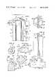
FIG. 1 is a side elevational view of a metallic sintered-body article, the same being an earth cutter bit, according to an embodiment of the invention;
FIG. 2 is an end elevational view, taken from the right-hand side of FIG. 1, of the article of FIG. 1;
FIG. 3 is a top or plan view of the article of FIGS. 1 and 2;
FIG. 4 is a pictorial and line illustration of an ingredient blends receiver for forming therein a general conformation of a to-be-compacted article;
FIG. 5 is a vertical, cross-sectional view of a bottom-bit type of earth cutter according to an embodiment of the invention;
FIG. 6 is a plan view of the FIG. 5 earth cutter;
FIG. 7 is a side elevation of a bottom-bit, according to an embodiment of the invention;
FIG. 8 is a cross-sectional view taken alongsection 8--8 of FIG. 7;
FIG. 9 is an enlarged depiction of a mix of tungsten carbide particles and steel powder;
FIG. 10 is an illustration of a particles and powder compacted preform;
FIG. 11 is a simplified illustration of the FIG. 10 preform in a forging die;
FIG. 12 is a depiction of a being-forged preform undergoing plane shear deformation;
FIG. 13 illustrates the presence of a void, within a fragmentary portion of a preform; and
FIG. 14 illustrates the progressive elimination of a given void, due to shear deformation of the preform in which it resides during forging.
The method of the invention will be particularly understood by reference by FIGS. 9 through 13, in which FIG. 9 illustrates an enlarged, small portion of a mixtungsten carbide particles 30 andsteel powder 32. In the manner well known in powder metallurgy techniques, theparticles 30 andpowder 32 are thoroughly mixed, in a mill or the like, so that thepowder 32 is uniformly diffused and coats theparticles 30. As is common in the techniques, wax or the like and an appropriate organic solvent are also used in the mix initially to fix the latter into a homogeneous mass. Then, the mass is pressed into a preform 34 (FIG. 10) of the to-be-produced article. The preform is then dry sintered; i.e., the sintering is carried out under temperatures which do not cause the hard constituent (tungsten carbide) and steel powder mass to melt. However, the wax binder, and an organic solvent of course, dissipate in a gaseous state. Finally, thesintered preform 34 is placed in a forging die 36 (FIG. 11), and forged into final conformation.
During the sintering, thepreform 34 acquires approximately a fifty to ninety percent total density. In the forging of thepreform 34, the product achieves its final conformation with a one hundred percent density. This arises from the fact that the forging causes plane shear deformation of the mass. FIG. 12 depicts theshear planes 38 which occur during the forging totally to eliminate any voids within the mass of thepreform 34. Prior art practices, such as hot isostatic sintering, impress equal forces on all sides of the preform mass. Now, typically, within the mass there will obtain a multiplicity of voids 40 (FIG. 13). The uniformly impressed forces of hot isostatic sintering do not eliminate the voids; rather, they diminish the size thereof, but render them highly pressured. Accordingly, these voids stress the portions of the mass in which they reside. In forging thepreform 34, according to our invention, the plane shearing subdivides the voids 40 (FIG. 14) and displaces theportions portions voids 40 and all diminishing elements thereof are non-existent. Hence, the finally conformed, forged article has a one hundred percent total density.
According to an embodiment of the invention, a metallic, sintered-body article 10, defined as an earth cutter bit, shown in FIGS. 1-3, is formed by mixing steel powder with tungsten carbide particles (FIG. 4), placing the mixed powder and particles in a receiver 12 and, according to known powder metallurgy techniques, as aforesaid, pressing the powder and particles mix into a compact or preform, and then dry-sintering the latter. However, toward (1) economizing on the amount of tungsten carbide used, (2) efficiently placing the latter in the article compact or preform, and (3) especially uniquely hardening or toughening thearticle 10 at its working end, the invention teaches the preparation of different powder and particles blends.
Thearticle 10, the earth cutter bit, has a workingend 14 with a workingface 16. Accordingly,end 14 is formed with an especially-carbide-enriched blend. Thearticle 10 may be considered, arbitrarily, as having three zones: zone "A", comprising the workingend 14, an intermediate zone "B", and a non-working or coupling end, zone "C". According to the novel method, thearticle 10 is formed from a first powder and particles blend of eighty-five percent tungsten carbide particles and fifteen percent steel powder which is consigned to zone "A". A blend of fifty-five percent tungsten carbide particles and forty-five percent steel powder is consigned to zone "B". Zone "C" is consigned one hundred percent steel powder.
The word consigned is used to denote that such powders and particles or powder and particles blends are introduced into a receiver, such as receiver 12, for the aforesaid zones. Yet, with the pre-forming pressing and dry-sintering of the being-formedarticle 10, the zone divisions become smooth transitions. At the "interface" of zones "A" and "B", following sintering, there may in fact obtain a composition of seventy percent tungsten carbide and thirty percent steel, and at the interface of zone "B" and "C", the resultant composition may be seventy or seventy-five percent steel and thirty or twenty-five percent tungsten carbide. In any event, at the cross-sections A--A, B--B and C--C will be found the powder or powder blends introduced into the receiver. Axially, through thearticle 10, however, there will be formed no sharp, distinct gradations of composition, hence, thearticle 10 is formed with no inherent "weak points". Rather, it is substantially, uniformly and progressively hardened or strengthened towardend 14. Following the dry-sintering, and in accordance with the novel method, thepre-formed article 10 is hot-forged, at approximately 1800 to 2000 degrees F., and with 40 to 70 tons per square inch, approximately, to conform thearticle 10 to final dimensions and configuration.
Thusarticle 10, for comprising an earth cutter bit, has a cuttinginsert 18 received and held in atransverse slot 20.Cuttings flushing holes 22 are arranged in close adjacency to theinsert 18 more efficiently to extract the cuttings from the workingface 16. The body of thearticle 10 is defined with a hexagonal configuration, the walls thereof, carried up close to the insert, provide uncommon strength to the security of theinsert 18. This, plus the tungsten carbide enrichment of zone "A" (as well as that of intermediate zone "B") provides a wear-resistant quality forface 16, and a sure retention ofinsert 18.
In one practice of the novel method, thearticle 10 is pre-formed with theslot 20, as noted, so that, following sintering, theinsert 18 can be emplaced. Then thearticle 10 is forged--the more securely to capture theinsert 18. By virtue of this novel method, theinsert 18, of a hard-metal carbide, such as tungsten carbide, need not have a typical, prior art depth for entry into the body of thearticle 10. For instance, in the depicted embodiment, theinsert 18 is approximately thirty-six mm. wide, but only approximately twelve mm. of its transverse dimension is needed to nest it in theslot 20. The carbide enrichment of zone "A" and the forging of thearticle 10 with the insert in place, obviate the need for more, expensive, further-nested depth of the insert.
Thearticle 10, alternatively, may be formed with a cutting element of protrusion, likeinsert 18, integrally formed as part of the body of the article. In this practice, zone "A" will comprise (in the forming receiver) a protruding area into which the zone "A" powder and particles mix migrates. The latter mix, then, can be ninety-five percent tungsten carbide particles to five percent steel powder, or it may be wholly tungsten carbide.
To define thearticle 10 with a recess (for an earth cutter insert, or the like), it is only necessary to interpose an obstruction into the receiver 12, as shown in FIG. 4. Here, the obstruction is an earth cutter, tungsten carbide button 18a. As, typically, sintering results in a shrinkage of the subject material, the degree of protrusion of the obstruction has to be pre-determined with the anticipated shrinkage taken into account. The receiver 12 has such aforesaid zones "A", "B", and "C" into which the tungsten carbide particles and steel powders are charged, and then a ram 24 (or the equivalent) is used to press the powders into a preform--for subsequent forging.
FIGS. 5 and 6 depict anarticle 10a into the nose of which is fixed the insert 18a. As witharticle 10, the metal zone circumscribing and bedding the insert 18a is a steel-powder matrix which is heavily enriched with tungsten carbide particles. Again, this circumstance, together with subsequent forging of the article perform, requires that not more than approximately forty percent of the height of the insert 18a need be nested into the workingface 16a.
Further to the teaching of how to economize on the usage of expensive tungsten carbide, is theinsert 18b shown in FIGS. 7 and 8. This insert embodiment also discloses an improved base configuration drawn to the purpose of securely nesting the insert in an article. Thebase 26, shown here to be 0.125-inch deep, is all that needs to be set into an aperture to retain theinsert 18b in place. Thebase 26 has a bottom-enlarged taper, with contributes to the locking-in of the insert; the greater, 0.175-inch "working" prominence is wholly exposed for useful work.
FIG. 8 shows that thebase 26 hasperipheral undulations 28 formed therein. Outboard of theundulations 28, shown in dashed outline, are the quantities of tungsten carbide saved by virtue of not having formed the base, as is conventional in the prior art, fully circular. The vertically-extending, rounded ribs, which obtain between theundulations 28, provide ample strength to theinsert 18b, and perhaps fifteen or twenty percent of tungsten carbide, which would otherwise have been expended in forming the insert, is unnecessary.
While we have described our invention in connection with specific embodiments, and methods of practice, it is to be clearly understood that this is done only by way of example and not as a limitation to the scope of our invention is set forth in the objects thereof and in the appended claims. For example, by taking teaching from our disclosure, it will occur to others that diversely-hardened earth cutter bits, similar to the tungsten carbide button 18a, can be formed. Such a bit can be preformed and forged with a central zone of perhaps ninety-five percent tungsten carbide particles and five percent steel powder, an adjacent zone of perhaps ninety percent tungsten carbide particles and ten percent steel powder, a next zone of perhaps eighty percent tungsten carbide particles and twenty percent steel powder, and so on, until an outermost zone may have but five or ten percent tungsten carbide particles and ninety or ninety-five percent steel powder. This teaching, clearly, can be employed in forming zone-hardened shafts, or bearing races, or bearing rollers, or tool surfaces (i.e., noses on hammer heads, and hardware-engaging recesses or coves in wrenches), or the tips or leading ends of (a) moil points, or (b) mining machine earth picks. The uses to which our teaching can be put have not been exhausted by the aforesaid discussion, and all practices of our novel method, and the fabrication of articles of whatever nature or conformation and purpose, defined in accordance with this disclosure, are deemed to be within the ambit of our teaching and comprised by the appended claims.
Claims (10)
1. A sintered and hot-forged article, having areas of differing hardness, comprising:
a metallic, sintered and forged body;
said body comprising a matrix homogeneously formed from a pair of ingredients comprising steel powder and tungsten carbide particles; and
said body having a first matrix cross-section constituted by a first ratio of one of said ingredients to the other thereof, and a second matrix cross-section constituted by a second ratio of said one ingredient to said other ingredient; and wherein
said first ratio is approximately eighty-five percent tungsten carbide to fifteen percent steel powder, and said second ratio is approximately fifty-five percent tungsten carbide to forty-five percent steel powder.
2. An article, according to claim 1, wherein:
said body has an insert-receiving recess formed therein; and further including
a hard-metal insert fixed in said recess; wherein
said insert has a greatest width of a given dimension; and
said recess has a depth of not more than approximately one-third said given dimension.
3. An article, according to claim 1, wherein:
said body has a working face, and a hard-metal formation extending outwardly from said face; and
said formation comprises means for disintegrating earth structures.
4. An article, according to claim 3, wherein:
said formation is an integral portion of said homogeneously-formed body matrix.
5. An article, according to claim 3, wherein:
said formation is a discrete insert held by said body.
6. An article, according to claim 5, wherein:
said insert has a given height dimension; and
said insert is held by said body through not more than approximately half of said given dimension.
7. An article, according to claim 5, wherein:
said insert has a base at one end and a nose portion contiguous therewith;
only said end base is held by said body; and
said base is formed with a tapered configuration having the greatest transverse dimension thereof spaced apart from said nose portion, and the smallest transverse dimension coincident with, and defining a commencement of, said nose portion.
8. An article, according to claim 7, wherein:
said base is not more than approximately 0.125-inch (3.175 mm.) in depth.
9. An article, according to claim 7, wherein:
said insert has a given height dimension; and
said base comprises not more than approximately forty percent of said dimension.
10. An article, according to claim 5, wherein:
said insert has a base at one end and a nose portion contiguous therewith; and
said base has an undulated periphery.
Priority Applications (2)
| Application Number | Priority Date | Filing Date | Title |
|---|---|---|---|
| US06/183,593US4484644A (en) | 1980-09-02 | 1980-09-02 | Sintered and forged article, and method of forming same |
| ZA815842AZA815842B (en) | 1980-09-02 | 1981-08-24 | A sintered and forged article,and method of forming same |
Applications Claiming Priority (1)
| Application Number | Priority Date | Filing Date | Title |
|---|---|---|---|
| US06/183,593US4484644A (en) | 1980-09-02 | 1980-09-02 | Sintered and forged article, and method of forming same |
Publications (1)
| Publication Number | Publication Date |
|---|---|
| US4484644Atrue US4484644A (en) | 1984-11-27 |
Family
ID=22673478
Family Applications (1)
| Application Number | Title | Priority Date | Filing Date |
|---|---|---|---|
| US06/183,593Expired - LifetimeUS4484644A (en) | 1980-09-02 | 1980-09-02 | Sintered and forged article, and method of forming same |
Country Status (2)
| Country | Link |
|---|---|
| US (1) | US4484644A (en) |
| ZA (1) | ZA815842B (en) |
Cited By (107)
| Publication number | Priority date | Publication date | Assignee | Title |
|---|---|---|---|---|
| US4595067A (en)* | 1984-01-17 | 1986-06-17 | Reed Tool Company | Rotary drill bit, parts therefor, and method of manufacturing thereof |
| US4597456A (en)* | 1984-07-23 | 1986-07-01 | Cdp, Ltd. | Conical cutters for drill bits, and processes to produce same |
| EP0312487A1 (en)* | 1987-10-13 | 1989-04-19 | Eastman Teleco Company | Earth boring drill bit with matrix displacing material |
| US4854405A (en)* | 1988-01-04 | 1989-08-08 | American National Carbide Company | Cutting tools |
| US4907665A (en)* | 1984-09-27 | 1990-03-13 | Smith International, Inc. | Cast steel rock bit cutter cones having metallurgically bonded cutter inserts |
| US5090491A (en)* | 1987-10-13 | 1992-02-25 | Eastman Christensen Company | Earth boring drill bit with matrix displacing material |
| US5135061A (en)* | 1989-08-04 | 1992-08-04 | Newton Jr Thomas A | Cutting elements for rotary drill bits |
| US5201917A (en)* | 1990-10-11 | 1993-04-13 | Technogenia S.A. | Plate with an abrasion-proof surface and process for the production thereof |
| US5431239A (en)* | 1993-04-08 | 1995-07-11 | Tibbitts; Gordon A. | Stud design for drill bit cutting element |
| WO1996020056A1 (en)* | 1994-12-23 | 1996-07-04 | Kennametal Inc. | Composite cermet articles and method of making |
| WO1996020057A1 (en)* | 1994-12-23 | 1996-07-04 | Kennametal Inc. | Composite cermet articles and method of making |
| US5623723A (en)* | 1995-08-11 | 1997-04-22 | Greenfield; Mark S. | Hard composite and method of making the same |
| US5839329A (en)* | 1994-03-16 | 1998-11-24 | Baker Hughes Incorporated | Method for infiltrating preformed components and component assemblies |
| US6073518A (en)* | 1996-09-24 | 2000-06-13 | Baker Hughes Incorporated | Bit manufacturing method |
| US6082461A (en)* | 1996-07-03 | 2000-07-04 | Ctes, L.C. | Bore tractor system |
| US6183687B1 (en) | 1995-08-11 | 2001-02-06 | Kennametal Inc. | Hard composite and method of making the same |
| US6200514B1 (en) | 1999-02-09 | 2001-03-13 | Baker Hughes Incorporated | Process of making a bit body and mold therefor |
| US6209420B1 (en) | 1994-03-16 | 2001-04-03 | Baker Hughes Incorporated | Method of manufacturing bits, bit components and other articles of manufacture |
| US6220375B1 (en) | 1999-01-13 | 2001-04-24 | Baker Hughes Incorporated | Polycrystalline diamond cutters having modified residual stresses |
| US6454030B1 (en) | 1999-01-25 | 2002-09-24 | Baker Hughes Incorporated | Drill bits and other articles of manufacture including a layer-manufactured shell integrally secured to a cast structure and methods of fabricating same |
| US6908688B1 (en) | 2000-08-04 | 2005-06-21 | Kennametal Inc. | Graded composite hardmetals |
| US20070290546A1 (en)* | 2006-06-16 | 2007-12-20 | Hall David R | A Wear Resistant Tool |
| US7320505B1 (en)* | 2006-08-11 | 2008-01-22 | Hall David R | Attack tool |
| US20080036276A1 (en)* | 2006-08-11 | 2008-02-14 | Hall David R | Lubricated Pick |
| US20080035383A1 (en)* | 2006-08-11 | 2008-02-14 | Hall David R | Non-rotating Pick with a Pressed in Carbide Segment |
| US20080036275A1 (en)* | 2006-08-11 | 2008-02-14 | Hall David R | Retainer Sleeve in a Degradation Assembly |
| US20080036271A1 (en)* | 2006-08-11 | 2008-02-14 | Hall David R | Method for Providing a Degradation Drum |
| US20080036269A1 (en)* | 2006-08-11 | 2008-02-14 | Hall David R | Hollow Pick Shank |
| US20080035386A1 (en)* | 2006-08-11 | 2008-02-14 | Hall David R | Pick Assembly |
| US20080042484A1 (en)* | 2006-08-21 | 2008-02-21 | Majagi Shivanand I | Cutting bit body and method for making the same |
| US7338135B1 (en) | 2006-08-11 | 2008-03-04 | Hall David R | Holder for a degradation assembly |
| US7347292B1 (en) | 2006-10-26 | 2008-03-25 | Hall David R | Braze material for an attack tool |
| USD566137S1 (en) | 2006-08-11 | 2008-04-08 | Hall David R | Pick bolster |
| US20080084106A1 (en)* | 2006-10-06 | 2008-04-10 | Marathe Aniruddha S | Rotatable cutting tool and cutting tool body |
| US20080099250A1 (en)* | 2006-10-26 | 2008-05-01 | Hall David R | Superhard Insert with an Interface |
| US7384105B2 (en) | 2006-08-11 | 2008-06-10 | Hall David R | Attack tool |
| US7387345B2 (en) | 2006-08-11 | 2008-06-17 | Hall David R | Lubricating drum |
| US7396086B1 (en)* | 2007-03-15 | 2008-07-08 | Hall David R | Press-fit pick |
| US7413256B2 (en) | 2006-08-11 | 2008-08-19 | Hall David R | Washer for a degradation assembly |
| US7419224B2 (en) | 2006-08-11 | 2008-09-02 | Hall David R | Sleeve in a degradation assembly |
| US20080211290A1 (en)* | 2006-08-11 | 2008-09-04 | Hall David R | Tapered Bore in a Pick |
| US20080246329A1 (en)* | 2006-08-11 | 2008-10-09 | Hall David R | Retention System |
| US20080250724A1 (en)* | 2007-04-12 | 2008-10-16 | Hall David R | High Impact Shearing Element |
| US7445294B2 (en) | 2006-08-11 | 2008-11-04 | Hall David R | Attack tool |
| US20080284234A1 (en)* | 2007-05-14 | 2008-11-20 | Hall David R | Pick with a Reentrant |
| USD581952S1 (en) | 2006-08-11 | 2008-12-02 | Hall David R | Pick |
| US7464993B2 (en)* | 2006-08-11 | 2008-12-16 | Hall David R | Attack tool |
| US20080309148A1 (en)* | 2006-08-11 | 2008-12-18 | Hall David R | Degradation Assembly Shield |
| US20080309149A1 (en)* | 2006-08-11 | 2008-12-18 | Hall David R | Braze Thickness Control |
| WO2008105915A3 (en)* | 2006-08-11 | 2009-02-05 | David R Hall | Thick pointed superhard material |
| US20090066149A1 (en)* | 2007-09-07 | 2009-03-12 | Hall David R | Pick with Carbide Cap |
| US20090146489A1 (en)* | 2006-08-11 | 2009-06-11 | Hall David R | Retention System |
| US7568770B2 (en) | 2006-06-16 | 2009-08-04 | Hall David R | Superhard composite material bonded to a steel body |
| US20090200855A1 (en)* | 2006-08-11 | 2009-08-13 | Hall David R | Manually Rotatable Tool |
| WO2009109283A1 (en)* | 2008-03-01 | 2009-09-11 | Ixetic Hückeswagen Gmbh | Oscillating motor housing |
| US7588102B2 (en) | 2006-10-26 | 2009-09-15 | Hall David R | High impact resistant tool |
| US7628233B1 (en) | 2008-07-23 | 2009-12-08 | Hall David R | Carbide bolster |
| US20090301788A1 (en)* | 2008-06-10 | 2009-12-10 | Stevens John H | Composite metal, cemented carbide bit construction |
| US7637574B2 (en) | 2006-08-11 | 2009-12-29 | Hall David R | Pick assembly |
| US20100006345A1 (en)* | 2008-07-09 | 2010-01-14 | Stevens John H | Infiltrated, machined carbide drill bit body |
| US7648210B2 (en) | 2006-08-11 | 2010-01-19 | Hall David R | Pick with an interlocked bolster |
| US7669938B2 (en) | 2006-08-11 | 2010-03-02 | Hall David R | Carbide stem press fit into a steel body of a pick |
| US20100054875A1 (en)* | 2006-08-11 | 2010-03-04 | Hall David R | Test Fixture that Positions a Cutting Element at a Positive Rake Angle |
| US7712693B2 (en) | 2006-08-11 | 2010-05-11 | Hall David R | Degradation insert with overhang |
| US7722127B2 (en) | 2006-08-11 | 2010-05-25 | Schlumberger Technology Corporation | Pick shank in axial tension |
| US7740414B2 (en) | 2005-03-01 | 2010-06-22 | Hall David R | Milling apparatus for a paved surface |
| US20100237135A1 (en)* | 2006-08-11 | 2010-09-23 | Schlumberger Technology Corporation | Methods For Making An Attack Tool |
| US20100242375A1 (en)* | 2009-03-30 | 2010-09-30 | Hall David R | Double Sintered Thermally Stable Polycrystalline Diamond Cutting Elements |
| US7832808B2 (en) | 2007-10-30 | 2010-11-16 | Hall David R | Tool holder sleeve |
| US20100326740A1 (en)* | 2009-06-26 | 2010-12-30 | Hall David R | Bonded Assembly Having Low Residual Stress |
| US7926883B2 (en) | 2007-05-15 | 2011-04-19 | Schlumberger Technology Corporation | Spring loaded pick |
| US7946657B2 (en) | 2006-08-11 | 2011-05-24 | Schlumberger Technology Corporation | Retention for an insert |
| US7950746B2 (en) | 2006-06-16 | 2011-05-31 | Schlumberger Technology Corporation | Attack tool for degrading materials |
| US8007050B2 (en) | 2006-08-11 | 2011-08-30 | Schlumberger Technology Corporation | Degradation assembly |
| US8007051B2 (en) | 2006-08-11 | 2011-08-30 | Schlumberger Technology Corporation | Shank assembly |
| AU2010206065B1 (en)* | 2010-07-30 | 2011-10-27 | Sandvik Intellectual Property Ab | Metal matrix pick |
| US8061457B2 (en) | 2009-02-17 | 2011-11-22 | Schlumberger Technology Corporation | Chamfered pointed enhanced diamond insert |
| US8118371B2 (en) | 2006-08-11 | 2012-02-21 | Schlumberger Technology Corporation | Resilient pick shank |
| US8201892B2 (en) | 2006-08-11 | 2012-06-19 | Hall David R | Holder assembly |
| US8215420B2 (en) | 2006-08-11 | 2012-07-10 | Schlumberger Technology Corporation | Thermally stable pointed diamond with increased impact resistance |
| US8250786B2 (en) | 2010-06-30 | 2012-08-28 | Hall David R | Measuring mechanism in a bore hole of a pointed cutting element |
| US8292372B2 (en) | 2007-12-21 | 2012-10-23 | Hall David R | Retention for holder shank |
| US8322796B2 (en) | 2009-04-16 | 2012-12-04 | Schlumberger Technology Corporation | Seal with contact element for pick shield |
| US8365845B2 (en) | 2007-02-12 | 2013-02-05 | Hall David R | High impact resistant tool |
| US8414085B2 (en) | 2006-08-11 | 2013-04-09 | Schlumberger Technology Corporation | Shank assembly with a tensioned element |
| US8449040B2 (en) | 2006-08-11 | 2013-05-28 | David R. Hall | Shank for an attack tool |
| US8485609B2 (en) | 2006-08-11 | 2013-07-16 | Schlumberger Technology Corporation | Impact tool |
| US8500209B2 (en) | 2006-08-11 | 2013-08-06 | Schlumberger Technology Corporation | Manually rotatable tool |
| US8540037B2 (en) | 2008-04-30 | 2013-09-24 | Schlumberger Technology Corporation | Layered polycrystalline diamond |
| US8567532B2 (en) | 2006-08-11 | 2013-10-29 | Schlumberger Technology Corporation | Cutting element attached to downhole fixed bladed bit at a positive rake angle |
| US8590644B2 (en) | 2006-08-11 | 2013-11-26 | Schlumberger Technology Corporation | Downhole drill bit |
| US8622155B2 (en) | 2006-08-11 | 2014-01-07 | Schlumberger Technology Corporation | Pointed diamond working ends on a shear bit |
| US8646848B2 (en) | 2007-12-21 | 2014-02-11 | David R. Hall | Resilient connection between a pick shank and block |
| US8668275B2 (en) | 2011-07-06 | 2014-03-11 | David R. Hall | Pick assembly with a contiguous spinal region |
| US8701799B2 (en) | 2009-04-29 | 2014-04-22 | Schlumberger Technology Corporation | Drill bit cutter pocket restitution |
| US8714285B2 (en) | 2006-08-11 | 2014-05-06 | Schlumberger Technology Corporation | Method for drilling with a fixed bladed bit |
| US8728382B2 (en) | 2011-03-29 | 2014-05-20 | David R. Hall | Forming a polycrystalline ceramic in multiple sintering phases |
| US9051795B2 (en) | 2006-08-11 | 2015-06-09 | Schlumberger Technology Corporation | Downhole drill bit |
| US9068410B2 (en) | 2006-10-26 | 2015-06-30 | Schlumberger Technology Corporation | Dense diamond body |
| WO2015168034A1 (en) | 2014-04-30 | 2015-11-05 | Us Synthetic Corporation | Cutting tool assemblies including superhard working surfaces and a rotary drum assembly comprising such cutting tool assemblies |
| US9434091B2 (en) | 2013-05-16 | 2016-09-06 | Us Synthetic Corporation | Road-removal system employing polycrystalline diamond compacts |
| USD798350S1 (en) | 2015-09-25 | 2017-09-26 | Us Synthetic Corporation | Cutting tool assembly |
| USD798920S1 (en) | 2015-09-25 | 2017-10-03 | Us Synthetic Corporation | Cutting tool assembly |
| US9915102B2 (en) | 2006-08-11 | 2018-03-13 | Schlumberger Technology Corporation | Pointed working ends on a bit |
| US10323514B2 (en) | 2013-05-16 | 2019-06-18 | Us Synthetic Corporation | Shear cutter pick milling system |
| US10408057B1 (en) | 2014-07-29 | 2019-09-10 | Apergy Bmcs Acquisition Corporation | Material-removal systems, cutting tools therefor, and related methods |
| US10648330B1 (en) | 2015-09-25 | 2020-05-12 | Us Synthetic Corporation | Cutting tool assemblies including superhard working surfaces, cutting tool mounting assemblies, material-removing machines including the same, and methods of use |
Citations (23)
| Publication number | Priority date | Publication date | Assignee | Title |
|---|---|---|---|---|
| US542542A (en)* | 1895-07-09 | Rock-drill | ||
| US1283542A (en)* | 1917-07-17 | 1918-11-05 | Eduardo Murphy | Boring-machine. |
| US1793757A (en)* | 1927-02-05 | 1931-02-24 | William H Smith | Process of uniting iron with other metals and elements |
| US1809780A (en)* | 1929-02-04 | 1931-06-09 | Ohio Instr Mfg Company | Producing metallic articles |
| US2313227A (en)* | 1938-08-04 | 1943-03-09 | Metal Carbides Corp | Roll for metal-rolling mills |
| US2582231A (en)* | 1949-02-05 | 1952-01-15 | Wheel Trueing Tool Co | Abrasive tool and method of making same |
| US3034589A (en)* | 1959-12-30 | 1962-05-15 | Sandvikens Jernverks Ab | Cutting insert for percussion drill bits |
| US3080009A (en)* | 1959-02-27 | 1963-03-05 | Timken Roller Bearing Co | Drill bit |
| US3142893A (en)* | 1961-06-20 | 1964-08-04 | Int Nickel Co | Heterogeneous sintered alloys |
| US3168925A (en)* | 1963-04-26 | 1965-02-09 | Ingersoll Rand Co | Cutting inserts for rock drill bits |
| US3175260A (en)* | 1961-09-06 | 1965-03-30 | Jersey Prod Res Co | Process for making metal carbide hard surfacing material and composite casting |
| US3715792A (en)* | 1970-10-21 | 1973-02-13 | Chromalloy American Corp | Powder metallurgy sintered corrosion and wear resistant high chromium refractory carbide alloy |
| US3734723A (en)* | 1970-09-04 | 1973-05-22 | Us Army | Compacted and sintered powder mass having a discrete cavity in the mass and method of forming |
| US3744993A (en)* | 1970-11-30 | 1973-07-10 | Aerojet General Co | Powder metallurgy process |
| US3761257A (en)* | 1971-06-14 | 1973-09-25 | W Dunn | Method of making a composite heavy duty bushing |
| US3778261A (en)* | 1970-05-04 | 1973-12-11 | Atomic Energy Authority Uk | Manufacturing composite articles |
| US3787205A (en)* | 1972-05-30 | 1974-01-22 | Int Nickel Co | Forging metal powders |
| US3802849A (en)* | 1969-01-31 | 1974-04-09 | Toyoda Chuo Kenkyusho Kk | Method for making a sintered body having integral portions of different density |
| US3816112A (en)* | 1970-11-05 | 1974-06-11 | Kempf Duria Werk | Method of coating steel plates with sintered friction layers |
| US3899821A (en)* | 1973-08-09 | 1975-08-19 | Kawasaki Steel Co | Method of making metal piece having high density from metal powder |
| US4002471A (en)* | 1973-09-24 | 1977-01-11 | Federal-Mogul Corporation | Method of making a through-hardened scale-free forged powdered metal article without heat treatment after forging |
| US4074778A (en)* | 1976-07-14 | 1978-02-21 | The United States Of America As Represented By The Secretary Of The Interior | Square hole drill |
| US4101318A (en)* | 1976-12-10 | 1978-07-18 | Erwin Rudy | Cemented carbide-steel composites for earthmoving and mining applications |
- 1980
- 1980-09-02USUS06/183,593patent/US4484644A/ennot_activeExpired - Lifetime
- 1981
- 1981-08-24ZAZA815842Apatent/ZA815842B/enunknown
Patent Citations (23)
| Publication number | Priority date | Publication date | Assignee | Title |
|---|---|---|---|---|
| US542542A (en)* | 1895-07-09 | Rock-drill | ||
| US1283542A (en)* | 1917-07-17 | 1918-11-05 | Eduardo Murphy | Boring-machine. |
| US1793757A (en)* | 1927-02-05 | 1931-02-24 | William H Smith | Process of uniting iron with other metals and elements |
| US1809780A (en)* | 1929-02-04 | 1931-06-09 | Ohio Instr Mfg Company | Producing metallic articles |
| US2313227A (en)* | 1938-08-04 | 1943-03-09 | Metal Carbides Corp | Roll for metal-rolling mills |
| US2582231A (en)* | 1949-02-05 | 1952-01-15 | Wheel Trueing Tool Co | Abrasive tool and method of making same |
| US3080009A (en)* | 1959-02-27 | 1963-03-05 | Timken Roller Bearing Co | Drill bit |
| US3034589A (en)* | 1959-12-30 | 1962-05-15 | Sandvikens Jernverks Ab | Cutting insert for percussion drill bits |
| US3142893A (en)* | 1961-06-20 | 1964-08-04 | Int Nickel Co | Heterogeneous sintered alloys |
| US3175260A (en)* | 1961-09-06 | 1965-03-30 | Jersey Prod Res Co | Process for making metal carbide hard surfacing material and composite casting |
| US3168925A (en)* | 1963-04-26 | 1965-02-09 | Ingersoll Rand Co | Cutting inserts for rock drill bits |
| US3802849A (en)* | 1969-01-31 | 1974-04-09 | Toyoda Chuo Kenkyusho Kk | Method for making a sintered body having integral portions of different density |
| US3778261A (en)* | 1970-05-04 | 1973-12-11 | Atomic Energy Authority Uk | Manufacturing composite articles |
| US3734723A (en)* | 1970-09-04 | 1973-05-22 | Us Army | Compacted and sintered powder mass having a discrete cavity in the mass and method of forming |
| US3715792A (en)* | 1970-10-21 | 1973-02-13 | Chromalloy American Corp | Powder metallurgy sintered corrosion and wear resistant high chromium refractory carbide alloy |
| US3816112A (en)* | 1970-11-05 | 1974-06-11 | Kempf Duria Werk | Method of coating steel plates with sintered friction layers |
| US3744993A (en)* | 1970-11-30 | 1973-07-10 | Aerojet General Co | Powder metallurgy process |
| US3761257A (en)* | 1971-06-14 | 1973-09-25 | W Dunn | Method of making a composite heavy duty bushing |
| US3787205A (en)* | 1972-05-30 | 1974-01-22 | Int Nickel Co | Forging metal powders |
| US3899821A (en)* | 1973-08-09 | 1975-08-19 | Kawasaki Steel Co | Method of making metal piece having high density from metal powder |
| US4002471A (en)* | 1973-09-24 | 1977-01-11 | Federal-Mogul Corporation | Method of making a through-hardened scale-free forged powdered metal article without heat treatment after forging |
| US4074778A (en)* | 1976-07-14 | 1978-02-21 | The United States Of America As Represented By The Secretary Of The Interior | Square hole drill |
| US4101318A (en)* | 1976-12-10 | 1978-07-18 | Erwin Rudy | Cemented carbide-steel composites for earthmoving and mining applications |
Cited By (182)
| Publication number | Priority date | Publication date | Assignee | Title |
|---|---|---|---|---|
| US4595067A (en)* | 1984-01-17 | 1986-06-17 | Reed Tool Company | Rotary drill bit, parts therefor, and method of manufacturing thereof |
| US4597456A (en)* | 1984-07-23 | 1986-07-01 | Cdp, Ltd. | Conical cutters for drill bits, and processes to produce same |
| US4907665A (en)* | 1984-09-27 | 1990-03-13 | Smith International, Inc. | Cast steel rock bit cutter cones having metallurgically bonded cutter inserts |
| US5090491A (en)* | 1987-10-13 | 1992-02-25 | Eastman Christensen Company | Earth boring drill bit with matrix displacing material |
| EP0312487A1 (en)* | 1987-10-13 | 1989-04-19 | Eastman Teleco Company | Earth boring drill bit with matrix displacing material |
| US4854405A (en)* | 1988-01-04 | 1989-08-08 | American National Carbide Company | Cutting tools |
| US5135061A (en)* | 1989-08-04 | 1992-08-04 | Newton Jr Thomas A | Cutting elements for rotary drill bits |
| US5201917A (en)* | 1990-10-11 | 1993-04-13 | Technogenia S.A. | Plate with an abrasion-proof surface and process for the production thereof |
| US5431239A (en)* | 1993-04-08 | 1995-07-11 | Tibbitts; Gordon A. | Stud design for drill bit cutting element |
| US5839329A (en)* | 1994-03-16 | 1998-11-24 | Baker Hughes Incorporated | Method for infiltrating preformed components and component assemblies |
| US6581671B2 (en) | 1994-03-16 | 2003-06-24 | Baker Hughes Incorporated | System for infiltrating preformed components and component assemblies |
| US6354362B1 (en) | 1994-03-16 | 2002-03-12 | Baker Hughes Incorporated | Method and apparatus for infiltrating preformed components and component assemblies |
| US6209420B1 (en) | 1994-03-16 | 2001-04-03 | Baker Hughes Incorporated | Method of manufacturing bits, bit components and other articles of manufacture |
| WO1996020056A1 (en)* | 1994-12-23 | 1996-07-04 | Kennametal Inc. | Composite cermet articles and method of making |
| US5677042A (en)* | 1994-12-23 | 1997-10-14 | Kennametal Inc. | Composite cermet articles and method of making |
| US5697042A (en)* | 1994-12-23 | 1997-12-09 | Kennametal Inc. | Composite cermet articles and method of making |
| US5776593A (en)* | 1994-12-23 | 1998-07-07 | Kennametal Inc. | Composite cermet articles and method of making |
| US5806934A (en)* | 1994-12-23 | 1998-09-15 | Kennametal Inc. | Method of using composite cermet articles |
| US5679445A (en)* | 1994-12-23 | 1997-10-21 | Kennametal Inc. | Composite cermet articles and method of making |
| WO1996020057A1 (en)* | 1994-12-23 | 1996-07-04 | Kennametal Inc. | Composite cermet articles and method of making |
| US5697046A (en)* | 1994-12-23 | 1997-12-09 | Kennametal Inc. | Composite cermet articles and method of making |
| US5623723A (en)* | 1995-08-11 | 1997-04-22 | Greenfield; Mark S. | Hard composite and method of making the same |
| US6183687B1 (en) | 1995-08-11 | 2001-02-06 | Kennametal Inc. | Hard composite and method of making the same |
| US6082461A (en)* | 1996-07-03 | 2000-07-04 | Ctes, L.C. | Bore tractor system |
| US6073518A (en)* | 1996-09-24 | 2000-06-13 | Baker Hughes Incorporated | Bit manufacturing method |
| US6089123A (en)* | 1996-09-24 | 2000-07-18 | Baker Hughes Incorporated | Structure for use in drilling a subterranean formation |
| US6220375B1 (en) | 1999-01-13 | 2001-04-24 | Baker Hughes Incorporated | Polycrystalline diamond cutters having modified residual stresses |
| US6872356B2 (en) | 1999-01-13 | 2005-03-29 | Baker Hughes Incorporated | Method of forming polycrystalline diamond cutters having modified residual stresses |
| US6521174B1 (en) | 1999-01-13 | 2003-02-18 | Baker Hughes Incorporated | Method of forming polycrystalline diamond cutters having modified residual stresses |
| US6655481B2 (en) | 1999-01-25 | 2003-12-02 | Baker Hughes Incorporated | Methods for fabricating drill bits, including assembling a bit crown and a bit body material and integrally securing the bit crown and bit body material to one another |
| US6454030B1 (en) | 1999-01-25 | 2002-09-24 | Baker Hughes Incorporated | Drill bits and other articles of manufacture including a layer-manufactured shell integrally secured to a cast structure and methods of fabricating same |
| US6200514B1 (en) | 1999-02-09 | 2001-03-13 | Baker Hughes Incorporated | Process of making a bit body and mold therefor |
| US6908688B1 (en) | 2000-08-04 | 2005-06-21 | Kennametal Inc. | Graded composite hardmetals |
| US7740414B2 (en) | 2005-03-01 | 2010-06-22 | Hall David R | Milling apparatus for a paved surface |
| US20070290546A1 (en)* | 2006-06-16 | 2007-12-20 | Hall David R | A Wear Resistant Tool |
| US7950746B2 (en) | 2006-06-16 | 2011-05-31 | Schlumberger Technology Corporation | Attack tool for degrading materials |
| US7469972B2 (en) | 2006-06-16 | 2008-12-30 | Hall David R | Wear resistant tool |
| US7568770B2 (en) | 2006-06-16 | 2009-08-04 | Hall David R | Superhard composite material bonded to a steel body |
| US7669674B2 (en) | 2006-08-11 | 2010-03-02 | Hall David R | Degradation assembly |
| US7992944B2 (en) | 2006-08-11 | 2011-08-09 | Schlumberger Technology Corporation | Manually rotatable tool |
| US20080036269A1 (en)* | 2006-08-11 | 2008-02-14 | Hall David R | Hollow Pick Shank |
| US20080035386A1 (en)* | 2006-08-11 | 2008-02-14 | Hall David R | Pick Assembly |
| US10378288B2 (en) | 2006-08-11 | 2019-08-13 | Schlumberger Technology Corporation | Downhole drill bit incorporating cutting elements of different geometries |
| US9915102B2 (en) | 2006-08-11 | 2018-03-13 | Schlumberger Technology Corporation | Pointed working ends on a bit |
| US7338135B1 (en) | 2006-08-11 | 2008-03-04 | Hall David R | Holder for a degradation assembly |
| US9708856B2 (en) | 2006-08-11 | 2017-07-18 | Smith International, Inc. | Downhole drill bit |
| USD566137S1 (en) | 2006-08-11 | 2008-04-08 | Hall David R | Pick bolster |
| US9366089B2 (en) | 2006-08-11 | 2016-06-14 | Schlumberger Technology Corporation | Cutting element attached to downhole fixed bladed bit at a positive rake angle |
| US9051795B2 (en) | 2006-08-11 | 2015-06-09 | Schlumberger Technology Corporation | Downhole drill bit |
| US8714285B2 (en) | 2006-08-11 | 2014-05-06 | Schlumberger Technology Corporation | Method for drilling with a fixed bladed bit |
| US7384105B2 (en) | 2006-08-11 | 2008-06-10 | Hall David R | Attack tool |
| US7387345B2 (en) | 2006-08-11 | 2008-06-17 | Hall David R | Lubricating drum |
| US7390066B2 (en) | 2006-08-11 | 2008-06-24 | Hall David R | Method for providing a degradation drum |
| US8622155B2 (en) | 2006-08-11 | 2014-01-07 | Schlumberger Technology Corporation | Pointed diamond working ends on a shear bit |
| US8590644B2 (en) | 2006-08-11 | 2013-11-26 | Schlumberger Technology Corporation | Downhole drill bit |
| US7410221B2 (en) | 2006-08-11 | 2008-08-12 | Hall David R | Retainer sleeve in a degradation assembly |
| US7413256B2 (en) | 2006-08-11 | 2008-08-19 | Hall David R | Washer for a degradation assembly |
| US7419224B2 (en) | 2006-08-11 | 2008-09-02 | Hall David R | Sleeve in a degradation assembly |
| US20080211290A1 (en)* | 2006-08-11 | 2008-09-04 | Hall David R | Tapered Bore in a Pick |
| US20080246329A1 (en)* | 2006-08-11 | 2008-10-09 | Hall David R | Retention System |
| US8567532B2 (en) | 2006-08-11 | 2013-10-29 | Schlumberger Technology Corporation | Cutting element attached to downhole fixed bladed bit at a positive rake angle |
| US7445294B2 (en) | 2006-08-11 | 2008-11-04 | Hall David R | Attack tool |
| US8534767B2 (en) | 2006-08-11 | 2013-09-17 | David R. Hall | Manually rotatable tool |
| USD581952S1 (en) | 2006-08-11 | 2008-12-02 | Hall David R | Pick |
| US8500210B2 (en) | 2006-08-11 | 2013-08-06 | Schlumberger Technology Corporation | Resilient pick shank |
| US7464993B2 (en)* | 2006-08-11 | 2008-12-16 | Hall David R | Attack tool |
| US20080309148A1 (en)* | 2006-08-11 | 2008-12-18 | Hall David R | Degradation Assembly Shield |
| US20080309149A1 (en)* | 2006-08-11 | 2008-12-18 | Hall David R | Braze Thickness Control |
| US7469971B2 (en) | 2006-08-11 | 2008-12-30 | Hall David R | Lubricated pick |
| US20080036275A1 (en)* | 2006-08-11 | 2008-02-14 | Hall David R | Retainer Sleeve in a Degradation Assembly |
| US7475948B2 (en) | 2006-08-11 | 2009-01-13 | Hall David R | Pick with a bearing |
| WO2008105915A3 (en)* | 2006-08-11 | 2009-02-05 | David R Hall | Thick pointed superhard material |
| US8500209B2 (en) | 2006-08-11 | 2013-08-06 | Schlumberger Technology Corporation | Manually rotatable tool |
| US20090146489A1 (en)* | 2006-08-11 | 2009-06-11 | Hall David R | Retention System |
| US20080035383A1 (en)* | 2006-08-11 | 2008-02-14 | Hall David R | Non-rotating Pick with a Pressed in Carbide Segment |
| US20090200855A1 (en)* | 2006-08-11 | 2009-08-13 | Hall David R | Manually Rotatable Tool |
| US8485609B2 (en) | 2006-08-11 | 2013-07-16 | Schlumberger Technology Corporation | Impact tool |
| US8453497B2 (en) | 2006-08-11 | 2013-06-04 | Schlumberger Technology Corporation | Test fixture that positions a cutting element at a positive rake angle |
| US8454096B2 (en) | 2006-08-11 | 2013-06-04 | Schlumberger Technology Corporation | High-impact resistant tool |
| US7600823B2 (en) | 2006-08-11 | 2009-10-13 | Hall David R | Pick assembly |
| US8449040B2 (en) | 2006-08-11 | 2013-05-28 | David R. Hall | Shank for an attack tool |
| US8434573B2 (en) | 2006-08-11 | 2013-05-07 | Schlumberger Technology Corporation | Degradation assembly |
| US8414085B2 (en) | 2006-08-11 | 2013-04-09 | Schlumberger Technology Corporation | Shank assembly with a tensioned element |
| US7635168B2 (en) | 2006-08-11 | 2009-12-22 | Hall David R | Degradation assembly shield |
| US7637574B2 (en) | 2006-08-11 | 2009-12-29 | Hall David R | Pick assembly |
| US8215420B2 (en) | 2006-08-11 | 2012-07-10 | Schlumberger Technology Corporation | Thermally stable pointed diamond with increased impact resistance |
| US8201892B2 (en) | 2006-08-11 | 2012-06-19 | Hall David R | Holder assembly |
| US7648210B2 (en) | 2006-08-11 | 2010-01-19 | Hall David R | Pick with an interlocked bolster |
| US7661765B2 (en) | 2006-08-11 | 2010-02-16 | Hall David R | Braze thickness control |
| US8136887B2 (en) | 2006-08-11 | 2012-03-20 | Schlumberger Technology Corporation | Non-rotating pick with a pressed in carbide segment |
| US7669938B2 (en) | 2006-08-11 | 2010-03-02 | Hall David R | Carbide stem press fit into a steel body of a pick |
| US20080036278A1 (en)* | 2006-08-11 | 2008-02-14 | Hall David R | Attack tool |
| US20100054875A1 (en)* | 2006-08-11 | 2010-03-04 | Hall David R | Test Fixture that Positions a Cutting Element at a Positive Rake Angle |
| US7712693B2 (en) | 2006-08-11 | 2010-05-11 | Hall David R | Degradation insert with overhang |
| US7717365B2 (en) | 2006-08-11 | 2010-05-18 | Hall David R | Degradation insert with overhang |
| US7722127B2 (en) | 2006-08-11 | 2010-05-25 | Schlumberger Technology Corporation | Pick shank in axial tension |
| US20080036276A1 (en)* | 2006-08-11 | 2008-02-14 | Hall David R | Lubricated Pick |
| US7744164B2 (en) | 2006-08-11 | 2010-06-29 | Schluimberger Technology Corporation | Shield of a degradation assembly |
| US20100237135A1 (en)* | 2006-08-11 | 2010-09-23 | Schlumberger Technology Corporation | Methods For Making An Attack Tool |
| US8118371B2 (en) | 2006-08-11 | 2012-02-21 | Schlumberger Technology Corporation | Resilient pick shank |
| US7832809B2 (en) | 2006-08-11 | 2010-11-16 | Schlumberger Technology Corporation | Degradation assembly shield |
| US8061784B2 (en) | 2006-08-11 | 2011-11-22 | Schlumberger Technology Corporation | Retention system |
| US8033616B2 (en) | 2006-08-11 | 2011-10-11 | Schlumberger Technology Corporation | Braze thickness control |
| US7871133B2 (en) | 2006-08-11 | 2011-01-18 | Schlumberger Technology Corporation | Locking fixture |
| US8033615B2 (en) | 2006-08-11 | 2011-10-11 | Schlumberger Technology Corporation | Retention system |
| US7946657B2 (en) | 2006-08-11 | 2011-05-24 | Schlumberger Technology Corporation | Retention for an insert |
| US7946656B2 (en) | 2006-08-11 | 2011-05-24 | Schlumberger Technology Corporation | Retention system |
| US7320505B1 (en)* | 2006-08-11 | 2008-01-22 | Hall David R | Attack tool |
| US7963617B2 (en) | 2006-08-11 | 2011-06-21 | Schlumberger Technology Corporation | Degradation assembly |
| US20080036271A1 (en)* | 2006-08-11 | 2008-02-14 | Hall David R | Method for Providing a Degradation Drum |
| US7992945B2 (en) | 2006-08-11 | 2011-08-09 | Schlumberger Technology Corporation | Hollow pick shank |
| US7997661B2 (en) | 2006-08-11 | 2011-08-16 | Schlumberger Technology Corporation | Tapered bore in a pick |
| US8007050B2 (en) | 2006-08-11 | 2011-08-30 | Schlumberger Technology Corporation | Degradation assembly |
| US8007051B2 (en) | 2006-08-11 | 2011-08-30 | Schlumberger Technology Corporation | Shank assembly |
| US8029068B2 (en) | 2006-08-11 | 2011-10-04 | Schlumberger Technology Corporation | Locking fixture for a degradation assembly |
| US20080042484A1 (en)* | 2006-08-21 | 2008-02-21 | Majagi Shivanand I | Cutting bit body and method for making the same |
| US7611210B2 (en)* | 2006-08-21 | 2009-11-03 | Kennametal Inc. | Cutting bit body and method for making the same |
| WO2008024193A1 (en)* | 2006-08-21 | 2008-02-28 | Kennametal Inc. | Cutting bit body and method for making the same |
| US20100007192A1 (en)* | 2006-08-21 | 2010-01-14 | Kennametal Inc. | Cutting bit body and method for making the same |
| US7458646B2 (en)* | 2006-10-06 | 2008-12-02 | Kennametal Inc. | Rotatable cutting tool and cutting tool body |
| US20080084106A1 (en)* | 2006-10-06 | 2008-04-10 | Marathe Aniruddha S | Rotatable cutting tool and cutting tool body |
| US9068410B2 (en) | 2006-10-26 | 2015-06-30 | Schlumberger Technology Corporation | Dense diamond body |
| US8109349B2 (en) | 2006-10-26 | 2012-02-07 | Schlumberger Technology Corporation | Thick pointed superhard material |
| US7353893B1 (en) | 2006-10-26 | 2008-04-08 | Hall David R | Tool with a large volume of a superhard material |
| US7665552B2 (en) | 2006-10-26 | 2010-02-23 | Hall David R | Superhard insert with an interface |
| US9540886B2 (en) | 2006-10-26 | 2017-01-10 | Schlumberger Technology Corporation | Thick pointed superhard material |
| US7347292B1 (en) | 2006-10-26 | 2008-03-25 | Hall David R | Braze material for an attack tool |
| US7588102B2 (en) | 2006-10-26 | 2009-09-15 | Hall David R | High impact resistant tool |
| US8960337B2 (en) | 2006-10-26 | 2015-02-24 | Schlumberger Technology Corporation | High impact resistant tool with an apex width between a first and second transitions |
| US20080099250A1 (en)* | 2006-10-26 | 2008-05-01 | Hall David R | Superhard Insert with an Interface |
| US10029391B2 (en) | 2006-10-26 | 2018-07-24 | Schlumberger Technology Corporation | High impact resistant tool with an apex width between a first and second transitions |
| US8028774B2 (en) | 2006-10-26 | 2011-10-04 | Schlumberger Technology Corporation | Thick pointed superhard material |
| US8365845B2 (en) | 2007-02-12 | 2013-02-05 | Hall David R | High impact resistant tool |
| US7401863B1 (en) | 2007-03-15 | 2008-07-22 | Hall David R | Press-fit pick |
| US7396086B1 (en)* | 2007-03-15 | 2008-07-08 | Hall David R | Press-fit pick |
| US20080250724A1 (en)* | 2007-04-12 | 2008-10-16 | Hall David R | High Impact Shearing Element |
| US9051794B2 (en) | 2007-04-12 | 2015-06-09 | Schlumberger Technology Corporation | High impact shearing element |
| US20080284234A1 (en)* | 2007-05-14 | 2008-11-20 | Hall David R | Pick with a Reentrant |
| US7594703B2 (en) | 2007-05-14 | 2009-09-29 | Hall David R | Pick with a reentrant |
| US8342611B2 (en) | 2007-05-15 | 2013-01-01 | Schlumberger Technology Corporation | Spring loaded pick |
| US7926883B2 (en) | 2007-05-15 | 2011-04-19 | Schlumberger Technology Corporation | Spring loaded pick |
| US20090066149A1 (en)* | 2007-09-07 | 2009-03-12 | Hall David R | Pick with Carbide Cap |
| US8038223B2 (en) | 2007-09-07 | 2011-10-18 | Schlumberger Technology Corporation | Pick with carbide cap |
| US7832808B2 (en) | 2007-10-30 | 2010-11-16 | Hall David R | Tool holder sleeve |
| US8292372B2 (en) | 2007-12-21 | 2012-10-23 | Hall David R | Retention for holder shank |
| US8646848B2 (en) | 2007-12-21 | 2014-02-11 | David R. Hall | Resilient connection between a pick shank and block |
| WO2009109283A1 (en)* | 2008-03-01 | 2009-09-11 | Ixetic Hückeswagen Gmbh | Oscillating motor housing |
| US8540037B2 (en) | 2008-04-30 | 2013-09-24 | Schlumberger Technology Corporation | Layered polycrystalline diamond |
| US8931854B2 (en) | 2008-04-30 | 2015-01-13 | Schlumberger Technology Corporation | Layered polycrystalline diamond |
| US20090301788A1 (en)* | 2008-06-10 | 2009-12-10 | Stevens John H | Composite metal, cemented carbide bit construction |
| US8261632B2 (en) | 2008-07-09 | 2012-09-11 | Baker Hughes Incorporated | Methods of forming earth-boring drill bits |
| US20100006345A1 (en)* | 2008-07-09 | 2010-01-14 | Stevens John H | Infiltrated, machined carbide drill bit body |
| US7628233B1 (en) | 2008-07-23 | 2009-12-08 | Hall David R | Carbide bolster |
| US8061457B2 (en) | 2009-02-17 | 2011-11-22 | Schlumberger Technology Corporation | Chamfered pointed enhanced diamond insert |
| US20100242375A1 (en)* | 2009-03-30 | 2010-09-30 | Hall David R | Double Sintered Thermally Stable Polycrystalline Diamond Cutting Elements |
| US8322796B2 (en) | 2009-04-16 | 2012-12-04 | Schlumberger Technology Corporation | Seal with contact element for pick shield |
| US8701799B2 (en) | 2009-04-29 | 2014-04-22 | Schlumberger Technology Corporation | Drill bit cutter pocket restitution |
| US20100326740A1 (en)* | 2009-06-26 | 2010-12-30 | Hall David R | Bonded Assembly Having Low Residual Stress |
| US8250786B2 (en) | 2010-06-30 | 2012-08-28 | Hall David R | Measuring mechanism in a bore hole of a pointed cutting element |
| CN103038446A (en)* | 2010-07-30 | 2013-04-10 | 山特维克知识产权股份有限公司 | Metal matrix composite mining pick and method of making |
| US20130207445A1 (en)* | 2010-07-30 | 2013-08-15 | Sandvik Intellectual Property Ab | Metal Matrix Composite Mining Pick and Method of Making |
| AU2010206065B1 (en)* | 2010-07-30 | 2011-10-27 | Sandvik Intellectual Property Ab | Metal matrix pick |
| US8728382B2 (en) | 2011-03-29 | 2014-05-20 | David R. Hall | Forming a polycrystalline ceramic in multiple sintering phases |
| US8668275B2 (en) | 2011-07-06 | 2014-03-11 | David R. Hall | Pick assembly with a contiguous spinal region |
| US9434091B2 (en) | 2013-05-16 | 2016-09-06 | Us Synthetic Corporation | Road-removal system employing polycrystalline diamond compacts |
| USD860275S1 (en) | 2013-05-16 | 2019-09-17 | Apergy Bmcs Acquisition Corporation | Cutting tool |
| US11926972B2 (en) | 2013-05-16 | 2024-03-12 | Us Synthetic Corporation | Shear cutter pick milling system |
| US11585215B2 (en) | 2013-05-16 | 2023-02-21 | Us Synthetic Corporation | Pick including polycrystalline diamond compact |
| USD828859S1 (en) | 2013-05-16 | 2018-09-18 | Us Synthetic Corporation | Cutting tool |
| US10316660B2 (en) | 2013-05-16 | 2019-06-11 | Apergy Bmcs Acquisition Corporation | Pick including polycrystalline diamond compact |
| US10323514B2 (en) | 2013-05-16 | 2019-06-18 | Us Synthetic Corporation | Shear cutter pick milling system |
| US11156087B2 (en) | 2013-05-16 | 2021-10-26 | Apergy Bmcs Acquisition Corporation | Pick including polycrystalline diamond compact |
| US11015303B2 (en) | 2013-05-16 | 2021-05-25 | Us Synthetic Corporation | Shear cutter pick milling system |
| USD809031S1 (en) | 2013-05-16 | 2018-01-30 | Us Synthetic Corporation | Cutting tool |
| US10414069B2 (en) | 2014-04-30 | 2019-09-17 | Us Synthetic Corporation | Cutting tool assemblies including superhard working surfaces, material-removing machines including cutting tool assemblies, and methods of use |
| US11078635B2 (en) | 2014-04-30 | 2021-08-03 | Apergy Bmcs Acquisition Corporation | Cutting tool assemblies including superhard working surfaces, material-removing machines including cutting tool assemblies, and methods of use |
| WO2015168034A1 (en) | 2014-04-30 | 2015-11-05 | Us Synthetic Corporation | Cutting tool assemblies including superhard working surfaces and a rotary drum assembly comprising such cutting tool assemblies |
| US10408057B1 (en) | 2014-07-29 | 2019-09-10 | Apergy Bmcs Acquisition Corporation | Material-removal systems, cutting tools therefor, and related methods |
| US11021953B1 (en) | 2014-07-29 | 2021-06-01 | Apergy Bmcs Acquisition Corporation | Material-removal systems, cutting tools therefor, and related methods |
| US10648330B1 (en) | 2015-09-25 | 2020-05-12 | Us Synthetic Corporation | Cutting tool assemblies including superhard working surfaces, cutting tool mounting assemblies, material-removing machines including the same, and methods of use |
| USD798350S1 (en) | 2015-09-25 | 2017-09-26 | Us Synthetic Corporation | Cutting tool assembly |
| USD798920S1 (en) | 2015-09-25 | 2017-10-03 | Us Synthetic Corporation | Cutting tool assembly |
Also Published As
| Publication number | Publication date |
|---|---|
| ZA815842B (en) | 1982-08-25 |
Similar Documents
| Publication | Publication Date | Title |
|---|---|---|
| US4484644A (en) | Sintered and forged article, and method of forming same | |
| EP3107676B1 (en) | Indexable cutting insert and milling tool | |
| US4592252A (en) | Rolling cutters for drill bits, and processes to produce same | |
| DE2722271C3 (en) | Process for the production of tools by composite sintering | |
| DE69209933T2 (en) | Fillet geometry on rotating diamond cutting tool | |
| DE3787791T2 (en) | Shredding elements for shredding machines. | |
| DE60001030T2 (en) | Cutting elements and their manufacturing processes | |
| DE2538377A1 (en) | SINTER BODY MANUFACTURED BY POWDER METALLURGY, USING THE SAME MANUFACTURED PRODUCTS AND THE PROCESS FOR THEIR PRODUCTION | |
| EP0169717A2 (en) | Rolling cutters for drill bits, and processes to produce same | |
| US7718116B2 (en) | Forged carburized powder metal part and method | |
| DE2851214A1 (en) | KNIFE WITH KNIFE HOLDER FOR SEPARATING MATERIAL, ESPECIALLY ROCK | |
| DE102016103850A1 (en) | Composite blanks and tooling for cutting applications | |
| DE3407427A1 (en) | DRILL BIT | |
| DE2752484A1 (en) | FLANGE BEARING CARTRIDGE OR BEARING FLANGE | |
| DE1502019A1 (en) | Tools and tooling made of sintered hard metal | |
| DE19924683C2 (en) | Method for equipping a chisel head of a shaft chisel and chisel | |
| DE112015005556T5 (en) | Process for producing a sintered component, sintered component and drill | |
| EP3562611B1 (en) | Tool | |
| DE102016108179A1 (en) | Cold-formed holding block and method for its production | |
| DE69512096T2 (en) | Ball bearing with high mechanical strength and its manufacturing process | |
| EP0841990A1 (en) | Working part and process for its production | |
| DD201984A5 (en) | WORK TOOL FOR THE SPATIAL WARM-FORMING OF STEEL OR OTHER STEEL METALS AND METHOD FOR THE PRODUCTION THEREOF | |
| DE19634314A1 (en) | Compound components for cutting tools | |
| DE102010031313A1 (en) | Tool i.e. chisel tool, for hand-held power tool, has shaft with spigot that is inserted into tool receiver, where wear-resistant component and adjacent region of spring steel are joined together in multi-orbital friction weld | |
| DE4307560C2 (en) | Process for the powder metallurgical production of a machine part exposed to different types of loads in certain areas |
Legal Events
| Date | Code | Title | Description |
|---|---|---|---|
| STCF | Information on status: patent grant | Free format text:PATENTED CASE | |
| AS | Assignment | Owner name:LONG AIRDOX COMPANY Free format text:ASSIGNMENT OF ASSIGNORS INTEREST;ASSIGNOR:INGERSOLL-RAND COMPANY;REEL/FRAME:006633/0789 Effective date:19930720 | |
| AS | Assignment | Owner name:DBT AMERICA INC., TEXAS Free format text:ASSIGNMENT OF ASSIGNORS INTEREST;ASSIGNOR:LONG-AIRDOX COMPANY;REEL/FRAME:011898/0852 Effective date:20010706 |