US4483665A - Bellows-type pump and metering system - Google Patents
Bellows-type pump and metering systemDownload PDFInfo
- Publication number
- US4483665A US4483665AUS06/340,644US34064482AUS4483665AUS 4483665 AUS4483665 AUS 4483665AUS 34064482 AUS34064482 AUS 34064482AUS 4483665 AUS4483665 AUS 4483665A
- Authority
- US
- United States
- Prior art keywords
- fluid
- bellows
- pump
- chamber
- working fluid
- Prior art date
- Legal status (The legal status is an assumption and is not a legal conclusion. Google has not performed a legal analysis and makes no representation as to the accuracy of the status listed.)
- Expired - Lifetime
Links
- 239000012530fluidSubstances0.000claimsabstractdescription103
- 238000005086pumpingMethods0.000claimsabstractdescription19
- 238000006073displacement reactionMethods0.000claimsabstractdescription9
- 230000007246mechanismEffects0.000claimsdescription29
- 238000004891communicationMethods0.000claimsdescription9
- 239000007788liquidSubstances0.000claimsdescription5
- 238000001914filtrationMethods0.000claimsdescription4
- 230000000903blocking effectEffects0.000claims2
- 230000008602contractionEffects0.000description5
- 230000000694effectsEffects0.000description5
- 230000006835compressionEffects0.000description4
- 238000007906compressionMethods0.000description4
- 230000008901benefitEffects0.000description3
- 229920002120photoresistant polymerPolymers0.000description3
- 230000009471actionEffects0.000description2
- 238000013022ventingMethods0.000description2
- XUIMIQQOPSSXEZ-UHFFFAOYSA-NSiliconChemical compound[Si]XUIMIQQOPSSXEZ-UHFFFAOYSA-N0.000description1
- 239000004809TeflonSubstances0.000description1
- 229920006362Teflon®Polymers0.000description1
- 230000002411adverseEffects0.000description1
- 230000009172burstingEffects0.000description1
- 238000013461designMethods0.000description1
- 230000008030eliminationEffects0.000description1
- 238000003379elimination reactionMethods0.000description1
- 230000006872improvementEffects0.000description1
- 238000004519manufacturing processMethods0.000description1
- 239000000463materialSubstances0.000description1
- 230000005499meniscusEffects0.000description1
- 230000004048modificationEffects0.000description1
- 238000012986modificationMethods0.000description1
- 230000002093peripheral effectEffects0.000description1
- 230000009467reductionEffects0.000description1
- 230000000717retained effectEffects0.000description1
- 239000004065semiconductorSubstances0.000description1
- 229910052710siliconInorganic materials0.000description1
- 239000010703siliconSubstances0.000description1
- 229910001220stainless steelInorganic materials0.000description1
- 239000010935stainless steelSubstances0.000description1
- 238000012360testing methodMethods0.000description1
- 235000012431wafersNutrition0.000description1
Images


Classifications
- F—MECHANICAL ENGINEERING; LIGHTING; HEATING; WEAPONS; BLASTING
- F04—POSITIVE - DISPLACEMENT MACHINES FOR LIQUIDS; PUMPS FOR LIQUIDS OR ELASTIC FLUIDS
- F04B—POSITIVE-DISPLACEMENT MACHINES FOR LIQUIDS; PUMPS
- F04B9/00—Piston machines or pumps characterised by the driving or driven means to or from their working members
- F04B9/08—Piston machines or pumps characterised by the driving or driven means to or from their working members the means being fluid
- F04B9/12—Piston machines or pumps characterised by the driving or driven means to or from their working members the means being fluid the fluid being elastic, e.g. steam or air
- F04B9/123—Piston machines or pumps characterised by the driving or driven means to or from their working members the means being fluid the fluid being elastic, e.g. steam or air having only one pumping chamber
- F04B9/125—Piston machines or pumps characterised by the driving or driven means to or from their working members the means being fluid the fluid being elastic, e.g. steam or air having only one pumping chamber reciprocating movement of the pumping member being obtained by a double-acting elastic-fluid motor
- F—MECHANICAL ENGINEERING; LIGHTING; HEATING; WEAPONS; BLASTING
- F04—POSITIVE - DISPLACEMENT MACHINES FOR LIQUIDS; PUMPS FOR LIQUIDS OR ELASTIC FLUIDS
- F04B—POSITIVE-DISPLACEMENT MACHINES FOR LIQUIDS; PUMPS
- F04B43/00—Machines, pumps, or pumping installations having flexible working members
- F04B43/08—Machines, pumps, or pumping installations having flexible working members having tubular flexible members
- F04B43/10—Pumps having fluid drive
- F04B43/107—Pumps having fluid drive the fluid being actuated directly by a piston
Definitions
- the present inventionrelates to a pump of the positive-displacement type and, more particularly, to an improvement in such a pump which utilizes a longitudinally-contractable bellows as the displacement means to pump relatively viscous fluids.
- Positive displacement pumps utilizing bellowsare well known.
- the fluid to be pumpedenters a hollow tubular bellows through a one-way check valve.
- the discharge end of the bellowsis constrained from movement, while the other end is connected to a reciprocating means which selectively works the bellows for longitudinal expansion and contraction.
- fluidis expelled from the bellows under pressure, which is to say, pumped.
- It is a well known characteristic of such pumpsthat, at high pumping pressures, considerable internal pressure is exerted on the bellows which, together with flexing during expansion and contraction, often results in fatigue and early rupture of the bellows.
- bellows-type displacement pumpsare well suited for such usage because, each time the bellows is filled and then compressed, a relatively equal quantity of pumped fluid is discharged. Such a consistent metering capability is highly desirable in situations where the objective is to consistently dispense relatively precise quantities of fluid.
- An example of one such dispensing applicationis in the semi-conductor industry where the pumped fluid may be highly viscous photoresist which is applied to silicon wafers during the manufacture of integrated circuits. In such metering applications it can be appreciated that, after dispensing, drips of the pumped fluid are to be avoided.
- auxillary devicesknown as "drawbacks" have been utilized. Typically, such devices create a negative pressure in the discharge line immediately after the pump discharge stroke is completed, and this keeps residual droplets from being discharged from the metering system.
- a primary object of the present inventionis to provide enhanced reliability and capacity in a pump of the positive displacement type which employs a longitudinally-contractable bellows as the displacement means.
- Another object of the present inventionis to provide an improved system for the metered pumping and dispensing of fluid comprising a bellows-type pump, a filter means for the pumped fluid, and a draw-back mechanism to prevent unwanted discharge (e.g., dripping) upon dispensing of the pumped fluid.
- Still another object of the present inventionis to provide an improved system for the pumping and dispensing of fluids, especially relatively viscous ones, comprising a bellows-type pump, a filter means for the pumped fluid, and a special check valve disposed in the fluid-flow conduit connecting the pump and the filter means to permit limited flow-back of the pumped fluid from the filter to the pump.
- a positive-displacement pump of the typewhich includes a longitudinally contractable tubular bellows to receive fluid for pumping, fluid-activated reciprocating means to expand and contract the bellows, means to selectively introduce working fluid to the reciprocating means to actuate the same, and means to cooperatively utilize working fluid to assist the reciprocating means in compressing the bellows.
- the pump of the present inventionincludes a rigid, fluid-tight chamber which surrounds the bellows, and means to selectively introduce working fluid into said chamber and to exhaust working fluid therefrom, whereby the working fluid assists in contracting the bellows as well as partially balancing the internal pressure on the bellows exerted by the pumped fluid.
- the pump of the present inventionis particularly well adapted to operate in a system for the metered pumping and dispensing of liquid where the system includes a drawback mechanism operated concurrently with, and by the same supply of pressurized working fluid, as the pump. Further, the improved system preferably includes a filter and a special check valve to relieve back pressure caused by the filter.
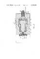
- FIG. 1is generally a longitudinal section of a pump according to the present invention, portions of which are shown cut away for facility of understanding;
- FIG. 2is a schematic view of a system for metered pumping, filtering, and dispensing of fluids incorporating the pump of FIG. 1, with portions of elements of the system shown cutaway and schematically views for purposes of clarity;
- FIG. 3is a sectional view of a drawback mechanism for use in the system of FIG. 2;
- FIG. 4is a sectional view of a check valve for use in the system of FIG. 2, enlarged for purposes of clarity.
- the pump 1 in FIG. 1includes a stationary hollow cylindrical housing 11 circular in cross-section, annular end members 12a and 12b sealingly fixed across the opposed ends of the housing 11, a tubular bellows 13 mounted for contractive-expansive movement within the housing 11 along its axial centerline, a tubular inlet member 15 which is sealingly fixed to one end of the bellows 13 and which is slidable through the aperture in the end member 12b to carry pumped fluid into the bellows, an outlet fitting 17 which fixedly and stationarily extends through the aperture in the annular end member 12a and which is sealingly connected to the opposite end of the bellows 13 to carry pumped fluid therefrom, an annular disk-like piston 19 which is fixed at its inner periphery to the inlet member and which effects a sliding seal at its outer periphery against the interior wall of the housing 11, and a port means 21 to introduce working fluid into the chamber 22 defined between the disk-like piston 21 and the end member 12b.
- a one-way check valve 23is mounted in flow communication to the inlet member 15 to control the direction of fluid flow therethrough.
- a one-way check valve 25is mounted to the outlet member 17 for directional control of fluid flow. (The direction of flow of the pumped fluid is indicated by the arrows in FIG. 1.)
- FIG. 1shows the bellows 13 to have been extended lengthwise, at which time fluid entered the bellows via the tubular inlet 15 and the one-way check valve 23.
- Action of the pump 1is then initiated by selective introduction of a working fluid, usually compressed air, into the chamber 22; this causes reciprocation of the disk-like piston 19 which, in turn, drives the inlet member 15 to force longitudinal contraction of the bellows 13.
- a working fluidusually compressed air
- FIG. 1shows a particularly simple and effective retraction mechanism comprising a pair of post members 45 and 46 fixedly extending from the end member 12b in a direction parallel to the longitudinal axis of the housing 11, a cross-link 47 which extends between the post members for sliding movement thereon and which is retained near its midpoint on the reciprocatably-moveable tubular inlet 15, and a pair of helical springs 49 and 50 mounted around each of the post members to bias the cross link 47 from the end member 12b.
- springs 49 and 50force retraction of the piston 19 and consequent expansion of the bellows 13 at such times as the pressurized working fluid is not exerting pressure against the piston 19.
- alternative meanscan be provided to retract the piston and, hence, to expand the bellows.
- the piston 19could be of the double-acting type and associated control valving could be provided so that the working fluid would serve to selectively move the piston in either direction of reciprocation.
- the illustrated embodimentis preferred because the primary forces exerted by the springs 49 and 50 act directly against the end member 12b and the piston 19; in other words, the spring forces are only indirectly transmitted to the bellows, thereby saving the bellows from fatigue.
- the critical wear component of the pumpis the bellows and, further, that fatigue of the bellows is caused by internal fluid pressure (i.e., the pumped fluid) as well as by flexing of the bellows in longitudinal expansion and contraction.
- the pump of FIG. 1includes an intermediate annular member 27 fixed within the housing 11.
- the interior wall of the housingis formed with a circular step 28 against which the annular member 27 seats, and with a peripheral slot 26 to receive a conventional C-ring 29 which retains the annular member 27 in position.
- a fluid-tight seal between the annular member 27 and the interior wall of the housing 11is conveniently accomplished, as shown, by providing an O-ring 30 located in a circular slot 32 formed in the outer periphery of the annular member.
- annular member 27To provide a seal in sliding engagement with the outside wall of the tubular inlet member 15, another O-ring 31 is fitted in a circular slot 33 formed in the inner periphery of the annular member 27.
- the annular member 27together with the afore-described end member 12a, provides a sealed chamber 37 within the housing 11 surrounding the bellows 13.
- the intermediate annular member 27also defines, in conjunction with the piston 19, a chamber 53.
- This chamberwould be fluid-tight but for a venting port 55 which is formed through the wall of the housing 11.
- the function of the port 55is to let air freely enter and escape from the chamber 53, so that the action of the piston 19 is not affected by the pressures which would exist were the chamber 53 sealed.
- a fluid-flow communication means 39is provided to introduce working fluid into the chamber 37 surrounding the bellows 13.
- the illustrated communication meansincludes a passageway 41 formed through the end member 12a and a conduit 43 connected at its one end in communication with the passageway 41 for carrying working fluid to chamber 37.
- the other end of the conduit 43is connected to a fitting 44 in communication with the port means 21, so that working fluid is concurrently carried into the piston chamber 22 as well as into the bellows chamber 37.
- the working fluidserves two purposes. First, the working fluid exerts pressure to displace the annular piston 19 within the chamber 22; this in turn, compresses the bellows 13 longitudinally. Second, the working fluid surrounds and supports the bellows.
- the external pressure of the working fluidacts to balance an equal internal pressure of the pumped fluid and therefore, the net pressure differential across the bellows is substantially reduced. Furthermore, as the bellows is compressed (with a consequent reduction in its external surface area) the pressure of the working fluid within the chamber 37 serves to cause further contraction. Thus, the net effect of the pressurized working fluid within chamber 37 is to augment and increase the forces which contract the bellows.
- the illustrated pumphas proven surprisingly effective in pumping viscous fluid such as photoresists, which have viscosities sometimes well exceeding 2000 centistokes. In part, the success is due to the increased pumping pressure obtainable with the illustrated pump; for example, discharge pressures of 200 psi or more can be maintained without adverse effect upon the life of the bellows. It should be appreciated that the high-pressure capabilities of the pump of the present invention permit it to be successfully utilized with a filtering mechanism as will be described below in conjunction with FIG. 2.
- the pump and bellowsare formed of stainless steel.
- the valves, diaphragms, and similar mechanismsare usually formed of Teflon or similar self-lubricating materials.
- the system in FIG. 2generally comprises the aforedescribed pump 1, a filter means 3 connected to the pump via a conduit 4 to receive and filter the pumped fluid, and a drawback mechanism 7 connected to a discharge fitting 5 on the filter 3 to prevent dripping or other unwanted discharge of the dispensed fluid through a pumped fluid dispensing conduit 8.
- a conventional one-way check valveis mounted in the discharge fitting 5 in location preceding the drawback mechanism 7 to prevent back flow into the filter when the drawback mechanism is actuated, as will be described hereinafter.
- the filter 3is a commercially available mechanism comprised of a stationary housing 63 to which a bowl 61 is sealingly affixed to receive pumped fluid.
- a filter element 65preferably of the cylindrical cartridge type, is sealingly mounted to the housing 63 so that all fluid which passes from the bowl 61 to discharge from the housing must first pass through the filter element.
- the filter mechanism 3also typically includes a vent means 66 to relieve air from the bowl 61, especially when operation of the system is initiated.
- the pump 1includes an exit fitting 67 which, preferably, contains a special one-way check valve which will be described hereinafter in conjunction with FIG. 4.
- the drawback mechanism 7generally includes a housing 71 fixed to the discharge fitting 5 from the filter 3. More particularly, the housing 71 has a hollow interior 74, a closed end 72b, and an open end 72a which is mounted in registry with an aperture (not shown) in communication with the interior of the pumped fluid dispensing conduit 8 connected to the discharge fitting 5. Mounted within the interior 74 of the housing is a reciprocatable mandrel 75 whose distal end 76a projects into the opening at the end 72a of the housing 71 and whose worked end 76b resides within the interior 74 of the housing.
- a non-foraminous, flexible diaphram 77which is also attached, near its center, to the distal end of the mandrel 75.
- a helical compression spring 79is mounted around the mandrel 75; one end of the spring 79 abutts the end wall 72a of the housing 71, and the other end seats against a step 80 forward on the mandrel 75.
- a second flexible diaphram 81is sealingly fixed across the interior 74 of the housing 71 and is attached to the worked end 76b of the mandrel 75.
- This second diaphramdefines, with the closed end 72b of the housing, a plenum chamber 83.
- a port 84is formed through the housing in communication with the interior of the chamber 83, and conduit means (not shown) is connected to the port 84 to carry pressurized working fluid into the chamber 83.
- the conduit meansalso is in fluid-flow communication with the line which carries working fluid to the pump 1 of FIG. 1.
- the draw-back mechanismfurther includes, in its preferred embodiment, an adjustment means 87 to selectively adjust the position of the mandrel 75.
- FIG. 3shows the position of the mandrel 75 at the completion of its "suction stroke".
- the mandrelremains in this position until the pumping stroke of the pump 1 begins.
- pressurized working fluidis introduced, via the port 84, into the plenum chamber 83 behind the diaphragm 81 of the draw-back mechanism.
- Thiscauses the chamber 83 to expand, as the pressure of the working fluid on the diaphram 81 forces the mandrel 75 to move towards the open end 72a of the housing.
- the first diaphragm 77is pressed into the fluid-flow channel of the pumped fluid dispensing conduit 8. The result of protrusion of the diaphram 77 is to displace or expel pumped fluid to discharge.
- the pressurized working fluidis vented from the plenum chamber 83, thereby relieving pressure on the diaphram 81.
- the spring 79forces the mandrel 75 towards the closed end 72b of the housing, and consequently, the diaphram 77 is drawn back from protrusion into the pumped fluid dispensing conduit 8.
- a suctionis created in the discharge channel to prevent droplets of pumped fluid from being unintentionally dispensed following the power stroke of the pump 1. (More exactly, the suction usually draws back a meniscus which forms at the outlet of the discharge channel.)
- FIG. 4shows a special valve 90 particularly adapted for use with the pumping-filtering system of FIG. 2.
- the primary function of valve 90is to act as a one-way check valve for pumped fluid; the auxilliary function of the valve 90 can best be understood by considering the operation of the filter 3 of FIG. 2.
- the pumped fluidexerts compressive pressure upon the filter element 65.
- the mechanical elasticity of the filter element 65causes it to expand to its original configuration. Expansion of the filter element, in turn, creates a back pressure which tends to force pumped fluid in the bowl 61 back toward the pump 1.
- the special valve of FIG. 4is provided to permit limited flow-back of the pumped fluid. (Without the special valve of FIG. 4, the pressures exerted by the mechanical properties of the filter element 65 can cause fluid leakage past the check valve immediately preceding the drawback mechanism.)
- the valve of FIG. 4includes a body 91 of generally cylindrical configuration having an open interior, preferably circular in cross-section.
- the body 91is stationarily mounted at a suitable location in the exit fitting 67 from the pump 1 (FIG. 2), so that all pumped fluid passes through the valve. (The direction of primary flow is indicated by the arrow in FIG. 4).
- the discharge end of the valve body 91is closed but for a central aperture 92 formed therein.
- the other end of the body 91has formed therein a slightly larger opening 93 to receive an inverted frustro-conical flow stoppage member 94.
- the exit fitting 67includes a tapered seat 95 to receive the frustro-conical stoppage member 94.
- a first helical compression spring 96is mounted within the body 91 to normally bias the stoppage member 94 against its seat 95.
- the special valve 90functions as a conventional one-way cleck valve.
- the primary flow of the pumped fluidis in the direction indicated.
- the pressure of the primary flow on the smaller end of the frustro-conical stoppage member 94causes the member to rise from its seat 95 and, concurrently, to compress the spring 96. Fluid then flows through the space between the frustro-conical member and the seat, enters the interior of the valve body 91, and then flows through the aperture 92 into the line 4 which carries pumped fluid to the filter 3 (FIG. 2).
- the frustro-conical stoppage member 94functions to block any flow in a direction opposite to the primary flow. That is, the spring 96 operates to force the frustro-conical member 94 securely and sealingly into its seat 95, thereby closing the flow passage.
- the valve 90 mechanismperforms the auxilliary function of permitting limited flow in the reverse direction (i.e., opposite to the arrow) under fluid pressure caused by expansion of the filter element 65.
- the structure which accomplishes this functionincludes a linear channel 101 formed along the axial center line of the frustro-conical stoppage member 94 and a stem member 103 slidably located in the channel.
- a ball-shaped piece 105is formed at the end of the stem member and a V-shaped seat 107 is formed in the smaller end of the frustro-conical member to receive the ball.
- the other end of the stem memberextends into the interior of the body 91.
- a second helical compression spring 109is mounted to surround the stem, with one end of the spring being fixed to the stem and the other end pressed against the frustro-conical member 94.
- the auxilliary function of the valve 90 of FIG. 4can now be understood, especially by considering conditions after completion of the pumping stroke of the pump 1, when expansion of the filter element 65 creates a reverse pressure of fluid in the conduit 4.
- pressure of the fluid on the free end of the stem member 103forces the stem to slide within the channel 101 against the force of the helical spring 109 and, thereby, to create a space between the ball 105 and its V-shaped seat 107 through which liquid can pass.
- the reverse flow of liquidthen allows the filter element 65 to expand.
- the spring 109forces retraction of the stem member 103 and re-seating of the ball 105 in its V-shaped seat 107. (It should be noted that the ball member remains firmly seated in a flow-blocking position when liquid flow is in the primary direction.)
- tension of the spring 109is usually chosen so as to maintain about one psi back pressure in the line 4.
- valve 90has been described, but that alternative embodiments could be employed.
- the first spring 96could be eliminated and the second spring 109 extended so that, while still being affixed to the stem member 103, one end of the spring 109 seats against the valve body 91 while the opposite end presses against the frustro-conical stoppage member 95.
- the function and operation of the valve 90would remain the same, with the only structural differences being elimination of the spring 96 and modification of the spring 109 on the stem member 103.
Landscapes
- Engineering & Computer Science (AREA)
- Mechanical Engineering (AREA)
- General Engineering & Computer Science (AREA)
- Reciprocating Pumps (AREA)
Abstract
Description
Claims (5)
Priority Applications (1)
| Application Number | Priority Date | Filing Date | Title |
|---|---|---|---|
| US06/340,644US4483665A (en) | 1982-01-19 | 1982-01-19 | Bellows-type pump and metering system |
Applications Claiming Priority (1)
| Application Number | Priority Date | Filing Date | Title |
|---|---|---|---|
| US06/340,644US4483665A (en) | 1982-01-19 | 1982-01-19 | Bellows-type pump and metering system |
Publications (1)
| Publication Number | Publication Date |
|---|---|
| US4483665Atrue US4483665A (en) | 1984-11-20 |
Family
ID=23334330
Family Applications (1)
| Application Number | Title | Priority Date | Filing Date |
|---|---|---|---|
| US06/340,644Expired - LifetimeUS4483665A (en) | 1982-01-19 | 1982-01-19 | Bellows-type pump and metering system |
Country Status (1)
| Country | Link |
|---|---|
| US (1) | US4483665A (en) |
Cited By (57)
| Publication number | Priority date | Publication date | Assignee | Title |
|---|---|---|---|---|
| US4601409A (en)* | 1984-11-19 | 1986-07-22 | Tritec Industries, Inc. | Liquid chemical dispensing system |
| US4822255A (en)* | 1978-10-25 | 1989-04-18 | Karl Eickmann | Pump for pressures exceeding one thousand atmospheres by the provision of a half-pressure chamber around a high pressure chamber between coned ring elements |
| US4824338A (en)* | 1978-10-25 | 1989-04-25 | Karl Eickmann | Pump arrangement which includes axially extending cylindrical ring noses on coned rings with a centering ring and seal ring radially of the face wherein two of the ring nose are oppositionally directed and laid together |
| US4950134A (en)* | 1988-12-27 | 1990-08-21 | Cybor Corporation | Precision liquid dispenser |
| US5061156A (en)* | 1990-05-18 | 1991-10-29 | Tritec Industries, Inc. | Bellows-type dispensing pump |
| EP0262151B1 (en)* | 1986-04-15 | 1992-01-29 | Millipore Corporation | Filter pump head assembly |
| US5085560A (en)* | 1990-01-12 | 1992-02-04 | Semitool, Inc. | Low contamination blending and metering systems for semiconductor processing |
| US5098377A (en)* | 1988-09-06 | 1992-03-24 | Baxter International Inc. | Multimodal displacement pump and dissolution system for same |
| US5167837A (en)* | 1989-03-28 | 1992-12-01 | Fas-Technologies, Inc. | Filtering and dispensing system with independently activated pumps in series |
| US5316181A (en)* | 1990-01-29 | 1994-05-31 | Integrated Designs, Inc. | Liquid dispensing system |
| US5490765A (en)* | 1993-05-17 | 1996-02-13 | Cybor Corporation | Dual stage pump system with pre-stressed diaphragms and reservoir |
| US5527161A (en)* | 1992-02-13 | 1996-06-18 | Cybor Corporation | Filtering and dispensing system |
| US5538407A (en)* | 1993-01-26 | 1996-07-23 | Groeneveld Transport Efficiency B.V. | Proportioner and fluid proportioning system |
| US5641270A (en)* | 1995-07-31 | 1997-06-24 | Waters Investments Limited | Durable high-precision magnetostrictive pump |
| US5662335A (en)* | 1994-09-19 | 1997-09-02 | Larsen; Richard R. | Pressure balanced bellows seal |
| US6478547B1 (en) | 1999-10-18 | 2002-11-12 | Integrated Designs L.P. | Method and apparatus for dispensing fluids |
| US6544005B2 (en) | 2000-11-28 | 2003-04-08 | Wade Metal Products Limited | Diaphragm for a diaphragm pump |
| US6554579B2 (en) | 2001-03-29 | 2003-04-29 | Integrated Designs, L.P. | Liquid dispensing system with enhanced filter |
| RU2208180C2 (en)* | 2001-04-20 | 2003-07-10 | Российский Федеральный Ядерный Центр - Всероссийский Научно-Исследовательский Институт Экспериментальной Физики | Proportioning pump (versions) |
| US20030226615A1 (en)* | 2002-06-10 | 2003-12-11 | Allen Todd Renell | Liquid dispensing system and method including same |
| US20040091378A1 (en)* | 2002-07-31 | 2004-05-13 | Kejr, Inc. | Mechanical bladder pump |
| US6752599B2 (en) | 2000-06-09 | 2004-06-22 | Alink M, Inc. | Apparatus for photoresist delivery |
| US20050184087A1 (en)* | 1998-11-23 | 2005-08-25 | Zagars Raymond A. | Pump controller for precision pumping apparatus |
| US20060070960A1 (en)* | 1999-11-30 | 2006-04-06 | Gibson Gregory M | Apparatus and methods for pumping high viscosity fluids |
| EP1705373A1 (en)* | 2005-02-03 | 2006-09-27 | Micro Mechatronic Technologies AG | Pump |
| US7138016B2 (en) | 1990-05-18 | 2006-11-21 | Semitool, Inc. | Semiconductor processing apparatus |
| US20070128061A1 (en)* | 2005-12-02 | 2007-06-07 | Iraj Gashgaee | Fixed volume valve system |
| US20070127511A1 (en)* | 2005-12-02 | 2007-06-07 | James Cedrone | I/O systems, methods and devices for interfacing a pump controller |
| US20070125797A1 (en)* | 2005-12-02 | 2007-06-07 | James Cedrone | System and method for pressure compensation in a pump |
| US20070125796A1 (en)* | 2005-12-05 | 2007-06-07 | James Cedrone | Error volume system and method for a pump |
| US7374409B2 (en)* | 2003-05-02 | 2008-05-20 | Nippon Pillar Packing Co., Ltd. | Reciprocating pump |
| US7494265B2 (en) | 2006-03-01 | 2009-02-24 | Entegris, Inc. | System and method for controlled mixing of fluids via temperature |
| US7547049B2 (en) | 2005-12-02 | 2009-06-16 | Entegris, Inc. | O-ring-less low profile fittings and fitting assemblies |
| US7684446B2 (en) | 2006-03-01 | 2010-03-23 | Entegris, Inc. | System and method for multiplexing setpoints |
| US20100178182A1 (en)* | 2009-01-09 | 2010-07-15 | Simmons Tom M | Helical bellows, pump including same and method of bellows fabrication |
| US20100178184A1 (en)* | 2009-01-09 | 2010-07-15 | Simmons Tom M | Bellows plungers having one or more helically extending features, pumps including such bellows plungers, and related methods |
| US7850431B2 (en) | 2005-12-02 | 2010-12-14 | Entegris, Inc. | System and method for control of fluid pressure |
| US7878765B2 (en) | 2005-12-02 | 2011-02-01 | Entegris, Inc. | System and method for monitoring operation of a pump |
| US8025486B2 (en) | 2005-12-02 | 2011-09-27 | Entegris, Inc. | System and method for valve sequencing in a pump |
| US8083498B2 (en) | 2005-12-02 | 2011-12-27 | Entegris, Inc. | System and method for position control of a mechanical piston in a pump |
| US8087429B2 (en) | 2005-11-21 | 2012-01-03 | Entegris, Inc. | System and method for a pump with reduced form factor |
| US8172546B2 (en) | 1998-11-23 | 2012-05-08 | Entegris, Inc. | System and method for correcting for pressure variations using a motor |
| US8292598B2 (en) | 2004-11-23 | 2012-10-23 | Entegris, Inc. | System and method for a variable home position dispense system |
| US20130243630A1 (en)* | 2012-03-15 | 2013-09-19 | John M. Simmons | Reciprocating pumps and related methods |
| WO2014016415A3 (en)* | 2012-07-27 | 2014-05-15 | Pressure Wave Systems Gmbh | Compressor device, and cooling device equipped therewith and refrigeration machine equipped therewith |
| US8753097B2 (en) | 2005-11-21 | 2014-06-17 | Entegris, Inc. | Method and system for high viscosity pump |
| US9631611B2 (en) | 2006-11-30 | 2017-04-25 | Entegris, Inc. | System and method for operation of a pump |
| US10391515B1 (en)* | 2018-05-11 | 2019-08-27 | Andrew Norman Kerlin | Viscous fluid applicator pump |
| WO2019169349A1 (en)* | 2018-03-01 | 2019-09-06 | Blacoh Fluid Controls, Inc. | Industrial flow and pressure stabilizer system |
| US10578098B2 (en) | 2005-07-13 | 2020-03-03 | Baxter International Inc. | Medical fluid delivery device actuated via motive fluid |
| CN111042967A (en)* | 2018-10-15 | 2020-04-21 | 现代自动车株式会社 | High pressure pump and method of compressing a fluid |
| US11346374B2 (en) | 2020-09-08 | 2022-05-31 | Blacoh Fluid Controls, Inc. | Fluid pulsation dampeners |
| CN114738250A (en)* | 2022-04-25 | 2022-07-12 | 俞贵伍 | High-temperature high-pressure mortar pump |
| US11478578B2 (en) | 2012-06-08 | 2022-10-25 | Fresenius Medical Care Holdings, Inc. | Medical fluid cassettes and related systems and methods |
| US11549523B2 (en) | 2021-04-27 | 2023-01-10 | Blacoh Fluid Controls, Inc. | Automatic fluid pump inlet stabilizers and vacuum regulators |
| USD993359S1 (en) | 2018-02-05 | 2023-07-25 | Blacoh Fluid Controls, Inc. | Valve |
| WO2024192225A1 (en)* | 2023-03-15 | 2024-09-19 | Westinghouse Electric Company Llc | Bellows pump for liquid metals |
Citations (12)
| Publication number | Priority date | Publication date | Assignee | Title |
|---|---|---|---|---|
| US1933454A (en)* | 1932-04-12 | 1933-10-31 | Sidney Arthur Alexander | Delivery valve of reciprocating pumps |
| US2212667A (en)* | 1938-07-18 | 1940-08-27 | Byron Jackson Co | Pumping apparatus |
| US2464095A (en)* | 1945-02-07 | 1949-03-08 | William L Nies | Pump |
| US2489783A (en)* | 1947-01-20 | 1949-11-29 | Vandervell Products Ltd | Shock absorber |
| US2896542A (en)* | 1955-11-18 | 1959-07-28 | Forghieri Renato | Fluid feeder and pressure intensifier for automatic operation by using the initial pressure of the fluid fed itself |
| US2951450A (en)* | 1956-04-17 | 1960-09-06 | John C Fisher | Fluid pump |
| US3131411A (en)* | 1961-10-05 | 1964-05-05 | Delman Co | Windshield clearing system |
| US3194169A (en)* | 1963-09-26 | 1965-07-13 | Laval Turbine | Pumps |
| US3492946A (en)* | 1968-05-23 | 1970-02-03 | Union Carbide Corp | Dual volume fluid sample pump |
| US3524714A (en)* | 1968-10-30 | 1970-08-18 | Us Air Force | Pneumatic bellows pump |
| US3749526A (en)* | 1970-05-23 | 1973-07-31 | Pirelli | Pumping apparatus with two separated fluid systems |
| US4139333A (en)* | 1977-05-18 | 1979-02-13 | Gca Corporation | Positive displacement flow through fluid pump |
- 1982
- 1982-01-19USUS06/340,644patent/US4483665A/ennot_activeExpired - Lifetime
Patent Citations (12)
| Publication number | Priority date | Publication date | Assignee | Title |
|---|---|---|---|---|
| US1933454A (en)* | 1932-04-12 | 1933-10-31 | Sidney Arthur Alexander | Delivery valve of reciprocating pumps |
| US2212667A (en)* | 1938-07-18 | 1940-08-27 | Byron Jackson Co | Pumping apparatus |
| US2464095A (en)* | 1945-02-07 | 1949-03-08 | William L Nies | Pump |
| US2489783A (en)* | 1947-01-20 | 1949-11-29 | Vandervell Products Ltd | Shock absorber |
| US2896542A (en)* | 1955-11-18 | 1959-07-28 | Forghieri Renato | Fluid feeder and pressure intensifier for automatic operation by using the initial pressure of the fluid fed itself |
| US2951450A (en)* | 1956-04-17 | 1960-09-06 | John C Fisher | Fluid pump |
| US3131411A (en)* | 1961-10-05 | 1964-05-05 | Delman Co | Windshield clearing system |
| US3194169A (en)* | 1963-09-26 | 1965-07-13 | Laval Turbine | Pumps |
| US3492946A (en)* | 1968-05-23 | 1970-02-03 | Union Carbide Corp | Dual volume fluid sample pump |
| US3524714A (en)* | 1968-10-30 | 1970-08-18 | Us Air Force | Pneumatic bellows pump |
| US3749526A (en)* | 1970-05-23 | 1973-07-31 | Pirelli | Pumping apparatus with two separated fluid systems |
| US4139333A (en)* | 1977-05-18 | 1979-02-13 | Gca Corporation | Positive displacement flow through fluid pump |
Cited By (96)
| Publication number | Priority date | Publication date | Assignee | Title |
|---|---|---|---|---|
| US4822255A (en)* | 1978-10-25 | 1989-04-18 | Karl Eickmann | Pump for pressures exceeding one thousand atmospheres by the provision of a half-pressure chamber around a high pressure chamber between coned ring elements |
| US4824338A (en)* | 1978-10-25 | 1989-04-25 | Karl Eickmann | Pump arrangement which includes axially extending cylindrical ring noses on coned rings with a centering ring and seal ring radially of the face wherein two of the ring nose are oppositionally directed and laid together |
| US4601409A (en)* | 1984-11-19 | 1986-07-22 | Tritec Industries, Inc. | Liquid chemical dispensing system |
| EP0262151B1 (en)* | 1986-04-15 | 1992-01-29 | Millipore Corporation | Filter pump head assembly |
| US5098377A (en)* | 1988-09-06 | 1992-03-24 | Baxter International Inc. | Multimodal displacement pump and dissolution system for same |
| US4950134A (en)* | 1988-12-27 | 1990-08-21 | Cybor Corporation | Precision liquid dispenser |
| US6251293B1 (en)* | 1989-03-28 | 2001-06-26 | Millipore Investment Holdings, Ltd. | Fluid dispensing system having independently operated pumps |
| US5167837A (en)* | 1989-03-28 | 1992-12-01 | Fas-Technologies, Inc. | Filtering and dispensing system with independently activated pumps in series |
| US6419841B1 (en) | 1989-03-28 | 2002-07-16 | Mykrolis Corporation | Fluid dispensing system |
| US5516429A (en)* | 1989-03-28 | 1996-05-14 | Fastar, Ltd. | Fluid dispensing system |
| US5085560A (en)* | 1990-01-12 | 1992-02-04 | Semitool, Inc. | Low contamination blending and metering systems for semiconductor processing |
| US5316181A (en)* | 1990-01-29 | 1994-05-31 | Integrated Designs, Inc. | Liquid dispensing system |
| US5061156A (en)* | 1990-05-18 | 1991-10-29 | Tritec Industries, Inc. | Bellows-type dispensing pump |
| US7138016B2 (en) | 1990-05-18 | 2006-11-21 | Semitool, Inc. | Semiconductor processing apparatus |
| US5527161A (en)* | 1992-02-13 | 1996-06-18 | Cybor Corporation | Filtering and dispensing system |
| US5538407A (en)* | 1993-01-26 | 1996-07-23 | Groeneveld Transport Efficiency B.V. | Proportioner and fluid proportioning system |
| US5490765A (en)* | 1993-05-17 | 1996-02-13 | Cybor Corporation | Dual stage pump system with pre-stressed diaphragms and reservoir |
| US5662335A (en)* | 1994-09-19 | 1997-09-02 | Larsen; Richard R. | Pressure balanced bellows seal |
| US5641270A (en)* | 1995-07-31 | 1997-06-24 | Waters Investments Limited | Durable high-precision magnetostrictive pump |
| US8172546B2 (en) | 1998-11-23 | 2012-05-08 | Entegris, Inc. | System and method for correcting for pressure variations using a motor |
| US7476087B2 (en) | 1998-11-23 | 2009-01-13 | Entegris, Inc. | Pump controller for precision pumping apparatus |
| US20050184087A1 (en)* | 1998-11-23 | 2005-08-25 | Zagars Raymond A. | Pump controller for precision pumping apparatus |
| US6478547B1 (en) | 1999-10-18 | 2002-11-12 | Integrated Designs L.P. | Method and apparatus for dispensing fluids |
| US6742993B2 (en) | 1999-10-18 | 2004-06-01 | Integrated Designs, L.P. | Method and apparatus for dispensing fluids |
| US7383967B2 (en) | 1999-11-30 | 2008-06-10 | Entegris, Inc. | Apparatus and methods for pumping high viscosity fluids |
| US20060070960A1 (en)* | 1999-11-30 | 2006-04-06 | Gibson Gregory M | Apparatus and methods for pumping high viscosity fluids |
| EP1235625A4 (en)* | 1999-11-30 | 2007-10-03 | Entegris Inc | Apparatus and methods for pumping high viscosity fluids |
| US6752599B2 (en) | 2000-06-09 | 2004-06-22 | Alink M, Inc. | Apparatus for photoresist delivery |
| US6544005B2 (en) | 2000-11-28 | 2003-04-08 | Wade Metal Products Limited | Diaphragm for a diaphragm pump |
| US6554579B2 (en) | 2001-03-29 | 2003-04-29 | Integrated Designs, L.P. | Liquid dispensing system with enhanced filter |
| RU2208180C2 (en)* | 2001-04-20 | 2003-07-10 | Российский Федеральный Ядерный Центр - Всероссийский Научно-Исследовательский Институт Экспериментальной Физики | Proportioning pump (versions) |
| US20030226615A1 (en)* | 2002-06-10 | 2003-12-11 | Allen Todd Renell | Liquid dispensing system and method including same |
| US20040091378A1 (en)* | 2002-07-31 | 2004-05-13 | Kejr, Inc. | Mechanical bladder pump |
| WO2004011763A3 (en)* | 2002-07-31 | 2004-08-12 | Kejr Inc | Mechanical bladder pump |
| US6877965B2 (en)* | 2002-07-31 | 2005-04-12 | Kejr, Inc. | Mechanical bladder pump |
| US7374409B2 (en)* | 2003-05-02 | 2008-05-20 | Nippon Pillar Packing Co., Ltd. | Reciprocating pump |
| US9617988B2 (en) | 2004-11-23 | 2017-04-11 | Entegris, Inc. | System and method for variable dispense position |
| US8814536B2 (en) | 2004-11-23 | 2014-08-26 | Entegris, Inc. | System and method for a variable home position dispense system |
| US8292598B2 (en) | 2004-11-23 | 2012-10-23 | Entegris, Inc. | System and method for a variable home position dispense system |
| EP1705373A1 (en)* | 2005-02-03 | 2006-09-27 | Micro Mechatronic Technologies AG | Pump |
| US10590924B2 (en) | 2005-07-13 | 2020-03-17 | Baxter International Inc. | Medical fluid pumping system including pump and machine chassis mounting regime |
| US10670005B2 (en) | 2005-07-13 | 2020-06-02 | Baxter International Inc. | Diaphragm pumps and pumping systems |
| US10578098B2 (en) | 2005-07-13 | 2020-03-03 | Baxter International Inc. | Medical fluid delivery device actuated via motive fluid |
| US12392335B2 (en) | 2005-07-13 | 2025-08-19 | Baxter International Inc. | Medical fluid pumping system having backflow prevention |
| US11384748B2 (en) | 2005-07-13 | 2022-07-12 | Baxter International Inc. | Blood treatment system having pulsatile blood intake |
| US9399989B2 (en) | 2005-11-21 | 2016-07-26 | Entegris, Inc. | System and method for a pump with onboard electronics |
| US8087429B2 (en) | 2005-11-21 | 2012-01-03 | Entegris, Inc. | System and method for a pump with reduced form factor |
| US8753097B2 (en) | 2005-11-21 | 2014-06-17 | Entegris, Inc. | Method and system for high viscosity pump |
| US8651823B2 (en) | 2005-11-21 | 2014-02-18 | Entegris, Inc. | System and method for a pump with reduced form factor |
| US7878765B2 (en) | 2005-12-02 | 2011-02-01 | Entegris, Inc. | System and method for monitoring operation of a pump |
| US8662859B2 (en) | 2005-12-02 | 2014-03-04 | Entegris, Inc. | System and method for monitoring operation of a pump |
| US8029247B2 (en) | 2005-12-02 | 2011-10-04 | Entegris, Inc. | System and method for pressure compensation in a pump |
| US8083498B2 (en) | 2005-12-02 | 2011-12-27 | Entegris, Inc. | System and method for position control of a mechanical piston in a pump |
| US7547049B2 (en) | 2005-12-02 | 2009-06-16 | Entegris, Inc. | O-ring-less low profile fittings and fitting assemblies |
| US7850431B2 (en) | 2005-12-02 | 2010-12-14 | Entegris, Inc. | System and method for control of fluid pressure |
| US20070128061A1 (en)* | 2005-12-02 | 2007-06-07 | Iraj Gashgaee | Fixed volume valve system |
| US8382444B2 (en) | 2005-12-02 | 2013-02-26 | Entegris, Inc. | System and method for monitoring operation of a pump |
| US20070127511A1 (en)* | 2005-12-02 | 2007-06-07 | James Cedrone | I/O systems, methods and devices for interfacing a pump controller |
| US9816502B2 (en) | 2005-12-02 | 2017-11-14 | Entegris, Inc. | System and method for pressure compensation in a pump |
| US7940664B2 (en) | 2005-12-02 | 2011-05-10 | Entegris, Inc. | I/O systems, methods and devices for interfacing a pump controller |
| US8025486B2 (en) | 2005-12-02 | 2011-09-27 | Entegris, Inc. | System and method for valve sequencing in a pump |
| US8678775B2 (en) | 2005-12-02 | 2014-03-25 | Entegris, Inc. | System and method for position control of a mechanical piston in a pump |
| US20070125797A1 (en)* | 2005-12-02 | 2007-06-07 | James Cedrone | System and method for pressure compensation in a pump |
| US9309872B2 (en) | 2005-12-02 | 2016-04-12 | Entegris, Inc. | System and method for position control of a mechanical piston in a pump |
| US9262361B2 (en) | 2005-12-02 | 2016-02-16 | Entegris, Inc. | I/O systems, methods and devices for interfacing a pump controller |
| US8870548B2 (en) | 2005-12-02 | 2014-10-28 | Entegris, Inc. | System and method for pressure compensation in a pump |
| US9025454B2 (en) | 2005-12-02 | 2015-05-05 | Entegris, Inc. | I/O systems, methods and devices for interfacing a pump controller |
| US20070125796A1 (en)* | 2005-12-05 | 2007-06-07 | James Cedrone | Error volume system and method for a pump |
| US7897196B2 (en) | 2005-12-05 | 2011-03-01 | Entegris, Inc. | Error volume system and method for a pump |
| US7494265B2 (en) | 2006-03-01 | 2009-02-24 | Entegris, Inc. | System and method for controlled mixing of fluids via temperature |
| US7684446B2 (en) | 2006-03-01 | 2010-03-23 | Entegris, Inc. | System and method for multiplexing setpoints |
| US7946751B2 (en) | 2006-03-01 | 2011-05-24 | Entegris, Inc. | Method for controlled mixing of fluids via temperature |
| US9631611B2 (en) | 2006-11-30 | 2017-04-25 | Entegris, Inc. | System and method for operation of a pump |
| US8636484B2 (en) | 2009-01-09 | 2014-01-28 | Tom M. Simmons | Bellows plungers having one or more helically extending features, pumps including such bellows plungers, and related methods |
| US20100178182A1 (en)* | 2009-01-09 | 2010-07-15 | Simmons Tom M | Helical bellows, pump including same and method of bellows fabrication |
| US20100178184A1 (en)* | 2009-01-09 | 2010-07-15 | Simmons Tom M | Bellows plungers having one or more helically extending features, pumps including such bellows plungers, and related methods |
| US9360000B2 (en)* | 2012-03-15 | 2016-06-07 | Graco Fluid Handling (A) Inc. | Reciprocating pumps and related methods |
| US10253761B2 (en) | 2012-03-15 | 2019-04-09 | White Knight Fluid Handling Inc. | Reciprocating pumps |
| KR20140145125A (en)* | 2012-03-15 | 2014-12-22 | 존 엠 시몬스 | Reciprocating pumps and related methods |
| US20130243630A1 (en)* | 2012-03-15 | 2013-09-19 | John M. Simmons | Reciprocating pumps and related methods |
| US11478578B2 (en) | 2012-06-08 | 2022-10-25 | Fresenius Medical Care Holdings, Inc. | Medical fluid cassettes and related systems and methods |
| WO2014016415A3 (en)* | 2012-07-27 | 2014-05-15 | Pressure Wave Systems Gmbh | Compressor device, and cooling device equipped therewith and refrigeration machine equipped therewith |
| US11231029B2 (en) | 2012-07-27 | 2022-01-25 | Pressure Wave Systems Gmbh | Compressor for a cooling device and a refrigeration machine |
| USD993359S1 (en) | 2018-02-05 | 2023-07-25 | Blacoh Fluid Controls, Inc. | Valve |
| WO2019169349A1 (en)* | 2018-03-01 | 2019-09-06 | Blacoh Fluid Controls, Inc. | Industrial flow and pressure stabilizer system |
| US10955079B2 (en) | 2018-03-01 | 2021-03-23 | Blacoh Fluid Controls, Inc. | Industrial flow and pressure stabilizer system |
| US10391515B1 (en)* | 2018-05-11 | 2019-08-27 | Andrew Norman Kerlin | Viscous fluid applicator pump |
| CN111042967A (en)* | 2018-10-15 | 2020-04-21 | 现代自动车株式会社 | High pressure pump and method of compressing a fluid |
| US11346374B2 (en) | 2020-09-08 | 2022-05-31 | Blacoh Fluid Controls, Inc. | Fluid pulsation dampeners |
| US11549523B2 (en) | 2021-04-27 | 2023-01-10 | Blacoh Fluid Controls, Inc. | Automatic fluid pump inlet stabilizers and vacuum regulators |
| US11828303B2 (en) | 2021-04-27 | 2023-11-28 | Blacoh Fluid Controls, Inc. | Automatic fluid pump inlet stabilizers and vacuum regulators |
| CN114738250B (en)* | 2022-04-25 | 2023-07-21 | 俞贵伍 | High-temperature high-pressure mortar pump |
| CN114738250A (en)* | 2022-04-25 | 2022-07-12 | 俞贵伍 | High-temperature high-pressure mortar pump |
| WO2024192225A1 (en)* | 2023-03-15 | 2024-09-19 | Westinghouse Electric Company Llc | Bellows pump for liquid metals |
| US20240309862A1 (en)* | 2023-03-15 | 2024-09-19 | Westinghouse Electric Company Llc | Bellows pump for liquid metals |
| US12392336B2 (en)* | 2023-03-15 | 2025-08-19 | Westinghouse Electric Company Llc | Bellows pump for liquid metals |
Similar Documents
| Publication | Publication Date | Title |
|---|---|---|
| US4483665A (en) | Bellows-type pump and metering system | |
| US3957399A (en) | Diaphragm pump | |
| US3811795A (en) | High pressure fluid intensifier and method | |
| US4008984A (en) | Pump apparatus | |
| US2807215A (en) | Variable displacement pump | |
| JPH08277812A (en) | Fluid pressure cylinder | |
| EP0125849A2 (en) | Piston accumulator | |
| US4387736A (en) | Fluid control apparatus | |
| US3884597A (en) | Reciprocating pump | |
| EP1096147A2 (en) | Pump with a pulsation suppression device | |
| US8021128B2 (en) | Fluid pump and motor unit | |
| JPH0689853B2 (en) | Extraction valve | |
| GB2179406A (en) | Dispensing pump for a fluid contained in a container | |
| GB2161221A (en) | Flexible chamber pump | |
| US4705458A (en) | Fluid operated pump | |
| EP1126164B1 (en) | Bellows pump for dispensing different liquids | |
| US4385640A (en) | Hydraulic unloader | |
| US4594057A (en) | Injector pump | |
| US3314365A (en) | Direct acting variable pump | |
| KR930003541B1 (en) | Reciprocating Pump Unit | |
| US6345962B1 (en) | Fluid operated pump | |
| US5285805A (en) | Stretch valve method and apparatus | |
| US4924901A (en) | In line valve | |
| RU2171398C1 (en) | Hydraulically-operated diaphragm proportioning pump | |
| US3192953A (en) | Check valves |
Legal Events
| Date | Code | Title | Description |
|---|---|---|---|
| AS | Assignment | Owner name:TRITEC INDUSTRIES, INC., 285 F SOBRANTE WAY, SUNNY Free format text:ASSIGNMENT OF ASSIGNORS INTEREST.;ASSIGNOR:HAUSER, HUGO;REEL/FRAME:003988/0093 Effective date:19820117 | |
| STCF | Information on status: patent grant | Free format text:PATENTED CASE | |
| FPAY | Fee payment | Year of fee payment:4 | |
| AS | Assignment | Owner name:RIPPEY CORPORATION A CORP. OF CALIFORNIA Free format text:ASSIGNMENT OF ASSIGNORS INTEREST.;ASSIGNOR:TRITEC INDUSTRIES, INC. A CORP. OF CALIFORNIA;REEL/FRAME:005808/0179 Effective date:19910814 | |
| FEPP | Fee payment procedure | Free format text:PAYOR NUMBER ASSIGNED (ORIGINAL EVENT CODE: ASPN); ENTITY STATUS OF PATENT OWNER: SMALL ENTITY | |
| AS | Assignment | Owner name:IPPEY CORPORATION, CALIFORNIA Free format text:ASSIGNMENT OF ASSIGNORS INTEREST.;ASSIGNOR:TRITEC INDUSTRIES, INC. A CORP. OF CALIFORNIA;REEL/FRAME:006041/0130 Effective date:19920306 | |
| FPAY | Fee payment | Year of fee payment:8 | |
| AS | Assignment | Owner name:RIPPEY CORPORATION, CALIFORNIA Free format text:MEMORANDUM OF SECURITY INTEREST;ASSIGNOR:CYBOR CORPORATION;REEL/FRAME:007541/0422 Effective date:19950518 Owner name:CYBOR CORPORATION, CALIFORNIA Free format text:ASSIGNMENT OF ASSIGNORS INTEREST;ASSIGNOR:RIPPEY CORPORATION;REEL/FRAME:007553/0554 Effective date:19950518 | |
| FEPP | Fee payment procedure | Free format text:PAYER NUMBER DE-ASSIGNED (ORIGINAL EVENT CODE: RMPN); ENTITY STATUS OF PATENT OWNER: SMALL ENTITY Free format text:PAYOR NUMBER ASSIGNED (ORIGINAL EVENT CODE: ASPN); ENTITY STATUS OF PATENT OWNER: SMALL ENTITY | |
| FPAY | Fee payment | Year of fee payment:12 | |
| REMI | Maintenance fee reminder mailed |