US4483202A - Ultrasonic flowmeter - Google Patents
Ultrasonic flowmeterDownload PDFInfo
- Publication number
- US4483202A US4483202AUS06/479,901US47990183AUS4483202AUS 4483202 AUS4483202 AUS 4483202AUS 47990183 AUS47990183 AUS 47990183AUS 4483202 AUS4483202 AUS 4483202A
- Authority
- US
- United States
- Prior art keywords
- ultrasonic
- time difference
- ultrasonic transducer
- transducer
- transducers
- Prior art date
- Legal status (The legal status is an assumption and is not a legal conclusion. Google has not performed a legal analysis and makes no representation as to the accuracy of the status listed.)
- Expired - Fee Related
Links
Images


Classifications
- G—PHYSICS
- G01—MEASURING; TESTING
- G01F—MEASURING VOLUME, VOLUME FLOW, MASS FLOW OR LIQUID LEVEL; METERING BY VOLUME
- G01F1/00—Measuring the volume flow or mass flow of fluid or fluent solid material wherein the fluid passes through a meter in a continuous flow
- G01F1/66—Measuring the volume flow or mass flow of fluid or fluent solid material wherein the fluid passes through a meter in a continuous flow by measuring frequency, phase shift or propagation time of electromagnetic or other waves, e.g. using ultrasonic flowmeters
- G01F1/667—Arrangements of transducers for ultrasonic flowmeters; Circuits for operating ultrasonic flowmeters
Definitions
- the present inventionrelates to an ultrasonic flowmeter which operates in accordance with the propagation time difference method.
- the propagation time difference methodis known as a method for measuring a flow rate (flow velocity or flow volume) of a fluid such as a gas or a liquid by utilizing an ultrasonic flowmeter.
- a pair of ultrasonic transducers 101 and 102are mounted in a conduit 100 such that they oppose each other on a line which is inclined by an angle ⁇ with respect to a fluid flowing direction in the conduit 100.
- a flow ratesuch as the flow velocity of a fluid, is measured in accordance with a propagation time difference ⁇ T between the ultrasonic propagation time Td in a downstream direction (i.e., the time required for an ultrasonic wave to propagate from the ultrasonic transducer 101 to the ultrasonic transducer 102) and ultrasonic propagation time Tu in an upstream direction (i.e., the time required for an ultrasonic wave to propagate from the ultrasonic transducer 102 to the ultrasonic transducer 101).
- a propagation time difference ⁇ Tbetween the ultrasonic propagation time Td in a downstream direction (i.e., the time required for an ultrasonic wave to propagate from the ultrasonic transducer 101 to the ultrasonic transducer 102) and ultrasonic propagation time Tu in an upstream direction (i.e., the time required for an ultrasonic wave to propagate from the ultrasonic transducer 102 to the ultrasonic transducer 101).
- lis the length of a region (recess) 103 or 104 which is free from the influence of the flow velocity of the fluid between the ultrasonic transducers 101 and 102,
- Lis the length of a region which is influenced by the flow velocity of the fluid between the ultrasonic transducers 101 and 102,
- Vis the flow velocity of the fluid
- ⁇is the angle formed between a direction indicated by an arrow 105 and a line (indicated by a dotted line) connecting the ultrasonic transducers 101 and 102, and
- Cis the sonic velocity in a fluid at rest.
- the flow velocity V of the fluidis given as follows:
- the propagation time difference ⁇ Tis generally as small as 10 -4 times the propagation time Td or Tu.
- the conduit 100 shown in FIG. 1comprises a water pipe which has a diameter of 100 mm, and the flow velocity V is 1 m/sec, the propagation time difference ⁇ T is about 150 nsec.
- the conduit 100comprises a gas pipe which has a diameter of 10 mm, and the fluid velocity is 10 cm/sec, the propagation time difference ⁇ T is about 27 nsec.
- the ultrasonic transducers 101 and 102are simultaneously driven by separate drivers, respectively, so as to decrease crosstalk components received by the ultrasonic transducers 101 and 102.
- a time differenceis measured as the propagation time difference ⁇ T when the ultrasonic wave from the ultrasonic transducer 101 is received by the ultrasonic transducer 102 and vice versa.
- the drive timings of the ultrasonic transducers 101 and 102may be different (corresponding to a difference ⁇ t) by several nanoseconds to several tens of nanoseconds in accordance with a difference between the switching characteristics (i.e.
- the difference ⁇ tis actually measured as part of the propagation time difference ⁇ T, so that an offset in the measured value for the flow velocity V occurs.
- the arrival timings of the ultrasonic waves from the ultrasonic transducer 101 at the ultrasonic transducer 102 and vice versaare determined in accordance with an Nth ultrasonic wave (where N corresponds, for example, to the wave which has a maximum magnitude).
- Ncorresponds, for example, to the wave which has a maximum magnitude.
- a frequency differenceis produced as an arrival timing difference ⁇ t'.
- the difference ⁇ t'is given as N(1/f1-1/f2). For example, if the frequencies f1 and f2 are 1.00 MHz and 1.01 MHz, respectively, and N is 5, the difference ⁇ t' is about 50 nsec.
- the difference ⁇ t'results in an offset in the measured value in the same manner as does the difference ⁇ t.
- the offset value caused by the differences ⁇ t and ⁇ t'is eliminated in the following manner.
- the ultrasonic transducers 101 and 102are driven when the fluid is interrupted in the conduit 100.
- an offsetis measured in accordance with equations (3) and (5).
- the offset previously measuredis subtracted from the measured value of the flow velocity V obtained in accordance with equation (5).
- an actual value of the flow velocity Vis obtained.
- the fluidmust be interrupted during the offset measurement.
- the conduit 100must be removed from the corresponding piping, or the fluid supply to the conduit 100 must be stopped. Therefore, the offset elimination method of the type described above is difficult to apply with a flowmeter which is operating continuously. Furthermore, a change in offset over time cannot be precisely measured.
- an ultrasonic flowmetercomprising: a conduit through which a fluid flows; a pair of ultrasonic transducers disposed in said conduit so as to oppose each other such that a line connecting said pair of ultrasonic transducers is inclined by a predetermined angle with respect to a fluid flowing direction; driving means for simultaneously driving said pair of ultrasonic transducers; time difference measuring means for measuring a primary time difference between a time measured when one ultrasonic transducer of said pair of ultrasonic transducers receives an ultrasonic wave which is radiated from the other ultrasonic transducer and a time measured when said other transducer receives an ultrasonic wave which is radiated from said one ultrasonic transducer, for measuring a secondary time difference between a time measured when said one ultrasonic transducer receives an ultrasonic wave which is radiated from said one ultrasonic transducer and reflected by said other ultrasonic transducer and a time measured when said other ultra
- FIG. 1is a sectional view of a conduit which has a pair of ultrasonic transducers used in an ultrasonic flowmeter according to a first embodiment of the present invention
- FIG. 2is a block diagram of the ultrasonic flowmeter according to the first embodiment of the present invention.
- FIG. 3is a block diagram of a signal detector shown in FIG. 2;
- FIG. 4, part (a) to part (j),are timing charts for explaining the mode of operation of the signal detector shown in FIG. 3;
- FIG. 5is a block diagram of a time difference measurement circuit shown in FIG. 2;
- FIG. 6, part (a) to part (j),are timing charts for explaining the mode of operation of the time difference measurement circuit shown in FIG. 5;
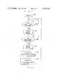
- FIG. 7is a flow chart for explaining the steps of calculating the flow velocity using the ultrasonic flowmeter according to the first embodiment.
- FIG. 8is a block diagram of an ultrasonic flowmeter according to a second embodiment of the present invention.
- FIG. 2is a block diagram showing the overall arrangement of an ultrasonic flowmeter according to a first embodiment of the present invention.
- a clock generator 200generates a clock signal 201 which has a sufficient period to measure primary and secondary time differences with a predetermined precision.
- a timing circuit 202generates various types of timing pulses to be used in related elements by dividing the clock signal 201.
- a drive timing pulse 203 among the output pulses from the timing circuit 202is supplied to drivers 204 and 205 so as to determine repetition drive timings of ultrasonic transducers 101 and 102, respectively, at predetermined periods.
- the drivers 204 and 205simultaneously drive the respective transducers 101 and 102 mounted in the conduit 100 described with reference to FIG. 1. Pulsed ultrasonic waves are produced by the transducers 101 and 102, respectively.
- the ultrasonic waves respectively produced by the transducers 101 and 102are propagated inside the conduit 100.
- Each ultrasonic waverequires a propagation time Td or Tu in accordance with equation (1) or (2) to reach the corresponding ultrasonic transducer.
- the ultrasonic waves respectively reaching the transducers 101 and 102are respectively reflected thereby.
- Reflected ultrasonic waves from the transducers 101 and 102are propagated through the conduit 100 in accordance with the propagation times Tu and Td obtained by equations (2) and (1), respectively.
- the reflected ultrasonic waves from the transducers 101 and 102are then received by the transducers 102 and 101, respectively.
- the ultrasonic wave radiated from the transducer 101 or reflected therebyrequires the propagation time Td to reach the transducer 102.
- the ultrasonic wave radiated from the transducer 102 or reflected therebyrequires the propagation time Tu to reach the transducer 101.
- a total propagation time Ta of the ultrasonic wave radiated from the transducer 101, reflected by the transducer 102 and received by the transducer 101is given as follows:
- a total propagation time Tb of the ultrasonic wave radiated from the transducer 102, reflected by the transducer 101 and received by the transducer 102is given as follows:
- Relation (8)is constantly established irrespective of the flow condition of the fluid.
- the secondary time difference ⁇ T2is subtracted from the primary time difference ⁇ T1, thereby obtaining the actual propagation time difference ⁇ T.
- a calculationis then performed using the propagation time difference ⁇ T in accordance with equation (5) so as to provide the flow velocity V which is free from an offset.
- the steps of measurement of the ultrasonic flowmeterwill be described hereinafter.
- the ultrasonic waves received by the transducers 101 and 102are converted to electric signals, respectively.
- the electric signals from the transducers 101 and 102are then amplified by receivers 206 and 207, respectively.
- Output signals 208 and 209 from the receivers 206 and 207are supplied to signal detectors 210 and 211, respectively.
- the signal detectors 210 and 211are circuits for producing signals required for measurements of the primary and secondary time differences ⁇ T1 and ⁇ T2 in accordance with timing pulses 212 and 213 supplied from the timing circuit 202, respectively.
- FIG. 3shows a detailed arrangement of the signal detector 210 (or 211).
- FIG. 4, part (a) to part (j),are timing charts for explaining the mode of operation of the signal detector 210 or 211.
- a terminal 300receives an output signal 208 (or 209) from the receiver 206 (or 207).
- Terminals 301 and 302receive gate timing pulses 212 and 213, respectively, from the timing circuit 202.
- FIG. 4 part (a)shows the drive timing pulse 203 supplied from the timing circuit 202 to the drivers 204 and 205.
- FIG. 4 part (b)shows a signal 208 (or 209).
- a signal 400is a leaked component of the output signal supplied from the driver 204 (205) to the receiver 206 (207).
- a signal 401is a component of the ultrasonic wave which is radiated from the transducer 102 (101) and received by the transducer 101 (102).
- a signal 402is a component of the ultrasonic wave which is radiated from the transducer 101 (102), is reflected by the transducer 102 (101), and is received by the transducer 101 (102).
- the gate timing pulses 212 and 213, respectively shown in FIG. 4, part (c) and part (d),are pulses generated in time intervals respectively corresponding to the periods of the signals 401 and 402.
- the centers of the durations of the gate timing pulses 212 and 213are set at times respectively lagged by time intervals T0 and 2T0 from the drive timing pulse 203.
- the time interval T0is given as follows:
- C0is the sonic velocity in the fluid under normal measuring conditions.
- Pulse widths 2t and 2t' of the gate timing pulses 212 and 213are set to correspond to about 15 to 20% and about 15 to 30% of the time interval T0, respectively.
- a period T of the timing pulse 203is set to be a time interval (e.g., T ⁇ 10T0) during which the ultrasonic wave radiated from the transducer 101 (102), reflected by the transducer 102 (101) and received by the transducer 101 (102) is sufficiently attenuated so as not to interfere with the next ultrasonic wave radiated from the transducer 101 (102).
- the signal 208 (209)is supplied to a level detector 303 and a zero cross detector 304.
- the signal 401 among signals 208 (209)is illustrated in an enlarged manner in FIG. 4 part (e).
- Output signals 305 and 306 from the level detector 303 and the zero cross detector 304are respectively shown in FIG. 4, part (f) and part (g), so as to correspond to the waveform: shown in FIG. 4 part (e).
- the signal 305is inverted every time the signal 208 (209) crosses a threshold level Vth (FIG. 4 part (e)) which is preset to be a few times the noise level.
- the signal 306is inverted every time the signal 208 (209) crosses zero level V0.
- the output signal 305 from the level detector 303is supplied to a set input end S of an R-S flip-flop (F/F) 309.
- the output signal 306 from the zero cross detector 304is supplied to an OR gate 307 together with the gate timing pulses 212 and 213.
- An output signal 308 from the OR gate 307is supplied to a reset input end R of the flip-flop 309. Since the output signal 308 from the OR gate 307 is kept high while the gate timing pulses 212 and 213 are not supplied to terminals 301 and 302, the flip-flop 309 is kept reset irrespective of the logic state of the output signal 305 from the level detector 303.
- the flip-flop 309When the gate timing pulses 212 and 213 are supplied to the terminals 301 and 302, the flip-flop 309 is set at the leading edge of the output signal 305 from the level detector 303, and is reset at the trailing edge of the output signal 306 from the zero cross detector 304. The flip-flop 309 then produces an output signal 310 as shown in FIG. 4 part (h).
- FIG. 4 part (j)An output signal 315 from the AND gate 314 is shown in FIG. 4 part (j).
- the leading edge of the signal 315corresponds to the zero-crossing point P of the maximum amplitude wave of the signal 401 shown in FIG. 4 part (e).
- the signal 315appears at a terminal 316 as an output signal 214 (215) from the signal detector 210 (211).
- the output signals 214 and 215 from the signal detectors 210 and 211, respectively,are supplied to a time difference measurement circuit 217.
- the time difference measurement circuit 217measures the primary and secondary time differences ⁇ T1 and ⁇ T2.
- FIG. 5A detailed arrangement of the time difference measurement circuit 217 is shown in FIG. 5.
- FIG. 6, part (a) to part (j),are timing charts for explaining the mode of operation of the time difference measurement circuit 217.
- a measurement timing pulse 216is supplied from the timing circuit 202 to a terminal 500.
- the pulse 216is then supplied to set input ends S of R-S flip-flops 503 and 504.
- the timing pulse 216comprises a pulse 216A generated at the same timing as the drive timing pulse 203 (FIG. 4 part (a)) and a pulse 216B which is delayed by a predetermined time T' from the pulse 216A, as shown in FIG. 6 part (a). It is noted that the time T' is fixed between the signal 402 (FIG. 4 part (b)) and the next signal 403.
- the output signals 214 and 215 from the signal detectors 210 and 211are supplied to reset input ends R of the flip-flops 503 and 504 through terminals 501 and 502, respectively.
- the signals 214 and 215are shown in FIG. 6, part (b) and part (c), respectively.
- Pulses 214A and 215A of the signals 214 and 215correspond to the signal 401, whereas pulses 214B and 215B correspond to the signal 402.
- Q output signals 505 and 506 from the flip-flops 503 and 504are shown in FIG. 6, part (d) and part (e), respectively.
- Q output signals 507 and 508 from the flip-flops 503 and 504are shown in FIG. 6, part (f) and part (g), respectively.
- the signals 505 and 508are supplied to an AND gate 510, and the signals 506 and 507 are supplied to an AND gate 511.
- a pulse 512Ais included in an output signal 512 from the AND gate 510, as shown in FIG. 6 part (h).
- the pulse 512Ahas a pulse width (which indicates the primary time difference ⁇ T1) corresponding to a time interval between the pulses 214A and 215A.
- a pulse 513Bis included in an output signal 513 from the AND gate 511, as shown in FIG. 6 part (i).
- the pulse 513Bhas a pulse width (which indicates the secondary time difference ⁇ T2) corresponding to a time interval between the pulses 214B and 215B.
- the output signals 512 and 513 from the AND gates 510 and 511are logic-ORed by an OR gate 514, as shown in FIG. 6 part (j).
- An output signal 515 from the OR gate 514is supplied to one input end of an AND gate 516.
- the clock signal 201 from the clock generator 200is supplied to the other input end of the AND gate 516 through a terminal 517.
- the AND gate 516is enabled when the output signal 515 from the OR gate 514 is kept high (i.e., time intervals corresponding to the differences ⁇ T1 or ⁇ T2, that is, the pulse widths of the pulses 515A and 515B, respectively).
- the clock signal passing through the AND gate 516is supplied to a counter 518 which then counts clock pulses, thereby measuring the primary and secondary time differences ⁇ T1 and ⁇ T2.
- the pulse having a width corresponding to the primary time difference ⁇ T1appears as the pulse 512A of the output signal 512 from the AND gate 510.
- the pulse corresponding to the primary time difference ⁇ T1appears as the pulse 513A of the output signal 513 from the AND gate 511.
- the pulse corresponding to the primary time difference ⁇ T1appears as the pulse 512A or 513A of the output signal 512 or 513 from the AND gate 510 or 511 in accordance with whichever of the ultrasonic waves from the transducers reaches the corresponding transducer faster than the other.
- the flow directioncan be determined in accordance with whether the pulse corresponding to the primary time difference ⁇ T1 appears as the pulse 512A or 513A, thereby determining a sign to be added to the primary time difference ⁇ T1.
- the pulse corresponding to the secondary time difference ⁇ T2appears as the pulse 512B or 513B of the output signal 512 or 513 of the AND gate 510 or 511.
- a sign to be added to the difference ⁇ T2is determined.
- One of the output signals 512 and 513 from the AND gates 510 and 512(e.g., the signal 513 in this embodiment) is used as a signal for designating the signs to be added, to the primary and secondary time difference ⁇ T1 and ⁇ T2, respectively.
- the sign "+”is added to the data of the first primary time difference ⁇ T1
- the sign "-"is added to the data of the secondary time difference ⁇ T2.
- a one-bit data which indicates the positive or negative signis stored in a sign bit (MSB) of output data 218 of the counter 518.
- the output data from the counter 518that is, the output data 218 from the time difference measurement circuit 217 is fetched in a CPU (central processing unit) 219 which comprises a microprocessor.
- the CPU 219executes the flow velocity computation routine in accordance with the flow chart shown in FIG. 7.
- start step 700a program stored in a ROM 222 is loaded in the CPU 219. It is then determined in step 701, in accordance with the timing pulse 220 from the timing circuit 202, whether or not the primary time difference ⁇ T1 has been measured. If YES in step 701, data 218 (sgn ⁇ T1) is stored in a RAM 223 through the CPU 219 in step 702.
- step 703It is then determined in step 703, in accordance with the timing pulse 221 from the timing circuit 202, whether or not the secondary time difference ⁇ T2 has been measured. If YES in step 703, data 218 (sgn ⁇ T2) is stored in the RAM 223 through the CPU 219 in step 704. When step 704 is completed, data sgn ⁇ T1 and sgn ⁇ T2 are read out from the RAM 223 and are fetched in the CPU 219. In step 705, propagation time difference data sgn ⁇ T with a sign is calculated in accordance with the flow direction of the fluid as follows:
- the data sgn ⁇ Tindicates the actual propagation time difference which does not include the differences ⁇ t and ⁇ t'.
- the data sgn ⁇ Tis stored in the RAM 223.
- step 706the data sgn ⁇ T stored in the RAM 223 is supplied to a fast arithmetic unit 224 through the CPU 219.
- the flow velocity Vis calculated by the arithmetic unit 224 as follows:
- Steps 701 to 706are repeated every time the transducers 101 and 102 are driven.
- Data of the flow velocity V which is calculated by the arithmetic unit 224is supplied to a D/A converter 225 through the CPU 219.
- An output signal from the D/A converter 225is supplied to a Y-axis input end of a CRT display 226, thereby displaying a waveform which indicates a change in flow velocity V over time on the CRT display 226. Integration of the value of the flow velocity V will yield a flow volume.
- FIG. 8shows an ultrasonic flowmeter according a second embodiment of the present invention.
- the arrangement for obtaining the data 218 (sgn ⁇ T1 and sgn ⁇ T2) of the flowmeteris the same as that of the first embodiment.
- the process for calculating the flow velocity V using the data 218 of the second embodimentdiffers from that of the first embodiment.
- the data 218is supplied to a switching circuit 800.
- the switching circuit 800supplies data 218 (sgn ⁇ T1) to a register 801.
- the switching circuit 800supplies data sgn ⁇ T2 to a register 802.
- the data sgn ⁇ T1 and sgn ⁇ T2are stored in the registers 801 and 802, respectively.
- the data sgn ⁇ T1 and sgn ⁇ T2are simultaneously read out from the registers 801 and 802 and are supplied to D/A converters 803 and 804, respectively.
- Output signals from the D/A converters 803 and 804are supplied to a differential amplifier 805.
- the differential amplifier 805multiplies a value obtained by subtracting the input data from each other by the coefficient K (eq. (12)), thereby obtaining the flow velocity V.
- An output signal from the differential amplifier 805is supplied to a Y-axis input end of a CRT display 806, thereby displaying a waveform which indicates a change in flow velocity V of the fluid.
Landscapes
- Physics & Mathematics (AREA)
- Electromagnetism (AREA)
- Fluid Mechanics (AREA)
- General Physics & Mathematics (AREA)
- Measuring Volume Flow (AREA)
Abstract
Description
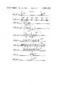
Td=2l/C+L/(C+Vcos θ) (1)
Tu=2l/C+L(C-Vcos θ) (2)
C.sup.2 ≈C.sup.2 -V.sup.2 cos.sup.2 θ (4)
V=(C.sup.2 /2L cos θ)·ΔT (5)
Ta=Td+Tu (6)
Tb=Tu+Td (7)
Ta=Tb (8)
T0≃(2l+L)/C0 (9)
sgnΔT=sgnΔT1-sgnΔT2 (10)
V=(C.sup.2 /2L cos θ)sgnΔT (11)
K=C.sup.2 /2L cos θ (12)
Claims (3)
V=(C.sup.2 /L cos θ)sgnΔT
sgnΔT=sgnΔT1-sgnΔT2
Applications Claiming Priority (2)
| Application Number | Priority Date | Filing Date | Title |
|---|---|---|---|
| JP57048857AJPS58167918A (en) | 1982-03-29 | 1982-03-29 | Ultrasonic wave flow speed measuring device |
| JP57-48857 | 1982-03-29 |
Publications (1)
| Publication Number | Publication Date |
|---|---|
| US4483202Atrue US4483202A (en) | 1984-11-20 |
Family
ID=12814935
Family Applications (1)
| Application Number | Title | Priority Date | Filing Date |
|---|---|---|---|
| US06/479,901Expired - Fee RelatedUS4483202A (en) | 1982-03-29 | 1983-03-29 | Ultrasonic flowmeter |
Country Status (4)
| Country | Link |
|---|---|
| US (1) | US4483202A (en) |
| EP (1) | EP0094148B1 (en) |
| JP (1) | JPS58167918A (en) |
| DE (1) | DE3361828D1 (en) |
Cited By (44)
| Publication number | Priority date | Publication date | Assignee | Title |
|---|---|---|---|---|
| US4726235A (en)* | 1986-03-12 | 1988-02-23 | Available Energy, Inc. | Ultrasonic instrument to measure the gas velocity and/or the solids loading in a flowing gas stream |
| US4817448A (en)* | 1986-09-03 | 1989-04-04 | Micro Motion, Inc. | Auto zero circuit for flow meter |
| US4882934A (en)* | 1986-03-12 | 1989-11-28 | Charles B. Leffert | Ultrasonic instrument to measure the gas velocity and/or the solids loading in a flowing gas stream |
| US4930358A (en)* | 1987-03-27 | 1990-06-05 | Tokyo Keiki Co., Ltd. | Method of and apparatus for measuring flow velocity by using ultrasonic waves |
| US5027662A (en)* | 1987-07-15 | 1991-07-02 | Micro Motion, Inc. | Accuracy mass flow meter with asymmetry and viscous damping compensation |
| US5123286A (en)* | 1990-04-20 | 1992-06-23 | Siemens Aktiengesellschaft | Electric measuring device for measuring the propagation delay of an electrical signal |
| US5493916A (en)* | 1991-06-25 | 1996-02-27 | Commonwealth Scientific and Industrial Research Organisation--AGL Consultancy Pty Ltd. | Mode suppression in fluid flow measurement |
| US5546813A (en)* | 1992-10-06 | 1996-08-20 | Caldon, Inc. | Apparatus for determining fluid flow |
| US5644090A (en)* | 1993-09-29 | 1997-07-01 | Siemens Measurements Limited | Gas meters |
| US5748504A (en)* | 1996-06-12 | 1998-05-05 | Welch Allyn, Inc. | Calibration method for use with ultrasonic flowmeters |
| US5753824A (en)* | 1996-06-12 | 1998-05-19 | Welch Allyn, Inc. | Sampling method and apparatus for use with ultrasonic flowmeters |
| US5777238A (en)* | 1996-06-12 | 1998-07-07 | Welch Allyn, Inc. | Driver-receiver apparatus for use with ultrasonic flowmeters |
| US5831175A (en)* | 1996-06-12 | 1998-11-03 | Welch Allyn, Inc. | Method and apparatus for correcting temperature variations in ultrasonic flowmeters |
| US5918281A (en)* | 1996-05-28 | 1999-06-29 | Nabulsi; Haz | Personal speedometer |
| US6305233B1 (en)* | 1995-10-19 | 2001-10-23 | Commonwealth Scientific And Industrial Research Organisation | Digital speed determination in ultrasonic flow measurements |
| US20030136193A1 (en)* | 2001-01-22 | 2003-07-24 | Naotoshi Fujimoto | Ultrasonic apparatus and method for measuring the concentration and flow rate of gas |
| US20050072248A1 (en)* | 2002-11-26 | 2005-04-07 | Takehiko Suginouchi | Ultrasonic flowmeter and ultrasonic flow rate measuring method |
| US20090171502A1 (en)* | 2007-12-28 | 2009-07-02 | Malema Engineering Corporation | Dispense Verification Meters |
| US7658114B1 (en) | 2008-11-17 | 2010-02-09 | General Electric Company | Ultrasonic flow meter |
| EP2275784A1 (en) | 1994-10-19 | 2011-01-19 | Panasonic Corporation | Flow Rate Measurement Method and Ultrasonic Flow Meter |
| AT510996A3 (en)* | 2012-04-13 | 2013-03-15 | Avl List Gmbh | Method for determining the distance between two ultrasonic transducers |
| CZ303779B6 (en)* | 2012-01-16 | 2013-05-02 | Zácek@Milos | Ultrasonic flow meter |
| US8857269B2 (en) | 2010-08-05 | 2014-10-14 | Hospira, Inc. | Method of varying the flow rate of fluid from a medical pump and hybrid sensor system performing the same |
| US20140305215A1 (en)* | 2012-04-12 | 2014-10-16 | Texas Instruments Incorporated | Ultrasonic flow meter |
| US10022498B2 (en) | 2011-12-16 | 2018-07-17 | Icu Medical, Inc. | System for monitoring and delivering medication to a patient and method of using the same to minimize the risks associated with automated therapy |
| US10166328B2 (en) | 2013-05-29 | 2019-01-01 | Icu Medical, Inc. | Infusion system which utilizes one or more sensors and additional information to make an air determination regarding the infusion system |
| US10342917B2 (en) | 2014-02-28 | 2019-07-09 | Icu Medical, Inc. | Infusion system and method which utilizes dual wavelength optical air-in-line detection |
| US10430761B2 (en) | 2011-08-19 | 2019-10-01 | Icu Medical, Inc. | Systems and methods for a graphical interface including a graphical representation of medical data |
| US10463788B2 (en) | 2012-07-31 | 2019-11-05 | Icu Medical, Inc. | Patient care system for critical medications |
| US10578474B2 (en) | 2012-03-30 | 2020-03-03 | Icu Medical, Inc. | Air detection system and method for detecting air in a pump of an infusion system |
| US10596316B2 (en) | 2013-05-29 | 2020-03-24 | Icu Medical, Inc. | Infusion system and method of use which prevents over-saturation of an analog-to-digital converter |
| US10635784B2 (en) | 2007-12-18 | 2020-04-28 | Icu Medical, Inc. | User interface improvements for medical devices |
| US10656894B2 (en) | 2017-12-27 | 2020-05-19 | Icu Medical, Inc. | Synchronized display of screen content on networked devices |
| US10850024B2 (en) | 2015-03-02 | 2020-12-01 | Icu Medical, Inc. | Infusion system, device, and method having advanced infusion features |
| US10874793B2 (en) | 2013-05-24 | 2020-12-29 | Icu Medical, Inc. | Multi-sensor infusion system for detecting air or an occlusion in the infusion system |
| US11135360B1 (en) | 2020-12-07 | 2021-10-05 | Icu Medical, Inc. | Concurrent infusion with common line auto flush |
| US11246985B2 (en) | 2016-05-13 | 2022-02-15 | Icu Medical, Inc. | Infusion pump system and method with common line auto flush |
| US11278671B2 (en) | 2019-12-04 | 2022-03-22 | Icu Medical, Inc. | Infusion pump with safety sequence keypad |
| US11324888B2 (en) | 2016-06-10 | 2022-05-10 | Icu Medical, Inc. | Acoustic flow sensor for continuous medication flow measurements and feedback control of infusion |
| US11344668B2 (en) | 2014-12-19 | 2022-05-31 | Icu Medical, Inc. | Infusion system with concurrent TPN/insulin infusion |
| US11344673B2 (en) | 2014-05-29 | 2022-05-31 | Icu Medical, Inc. | Infusion system and pump with configurable closed loop delivery rate catch-up |
| US11883361B2 (en) | 2020-07-21 | 2024-01-30 | Icu Medical, Inc. | Fluid transfer devices and methods of use |
| US12350233B2 (en) | 2021-12-10 | 2025-07-08 | Icu Medical, Inc. | Medical fluid compounding systems with coordinated flow control |
| USD1091564S1 (en) | 2021-10-13 | 2025-09-02 | Icu Medical, Inc. | Display screen or portion thereof with graphical user interface for a medical device |
Families Citing this family (10)
| Publication number | Priority date | Publication date | Assignee | Title |
|---|---|---|---|---|
| GB2197472A (en)* | 1986-11-17 | 1988-05-18 | British Gas Plc | Ultrasonic flowmeter |
| DE3808913C1 (en)* | 1988-03-17 | 1989-12-07 | Rheometron Ag, Basel, Ch | Method and circuit arrangement for processing the measuring signals from flow meters |
| US5369998A (en)* | 1989-12-12 | 1994-12-06 | Commonwealth Scientific And Industrial Research Organisation | Ultrasonic mass flow meter for solids suspended in a gas stream |
| JP4556253B2 (en)* | 1999-06-24 | 2010-10-06 | パナソニック株式会社 | Flowmeter |
| JP4792653B2 (en)* | 2001-04-20 | 2011-10-12 | パナソニック株式会社 | Flowmeter |
| JP5092414B2 (en)* | 2007-01-16 | 2012-12-05 | パナソニック株式会社 | Flow velocity or flow rate measuring device |
| JP5092413B2 (en)* | 2007-01-16 | 2012-12-05 | パナソニック株式会社 | Flow velocity or flow rate measuring device |
| JP5034510B2 (en)* | 2007-01-19 | 2012-09-26 | パナソニック株式会社 | Flow velocity or flow rate measuring device and its program |
| JP2013064643A (en)* | 2011-09-16 | 2013-04-11 | Toyo Gas Meter Kk | Method and apparatus for correcting zero point of ultrasonic flowmeter |
| CN113323612B (en)* | 2021-08-03 | 2022-01-28 | 中国石油集团川庆钻探工程有限公司 | Anti-overflow pipe fluid detection device, comprehensive processing system and identification method |
Citations (9)
| Publication number | Priority date | Publication date | Assignee | Title |
|---|---|---|---|---|
| US3209591A (en)* | 1962-08-17 | 1965-10-05 | Westinghouse Electric Corp | Acoustic flow meter |
| CH511437A (en)* | 1966-08-03 | 1971-08-15 | Westinghouse Electric Corp | Device for measuring the flow rate of a liquid |
| US3918304A (en)* | 1973-11-23 | 1975-11-11 | Westinghouse Electric Corp | Flowmeter computer |
| US3935735A (en)* | 1974-09-03 | 1976-02-03 | Badger Meter, Inc. | Ultrasonic flow meter |
| US4052896A (en)* | 1975-11-26 | 1977-10-11 | Badger Meter, Inc. | Ultrasonic flow meter |
| EP0017475A1 (en)* | 1979-04-05 | 1980-10-15 | Westinghouse Electric Corporation | Acoustic flowmeter with Reynolds number compensation |
| JPS5643510A (en)* | 1979-09-17 | 1981-04-22 | Yokogawa Hokushin Electric Corp | Flowmeter |
| JPS5777915A (en)* | 1980-10-31 | 1982-05-15 | Toshiba Corp | Fluid measuring apparatus |
| US4334434A (en)* | 1979-04-11 | 1982-06-15 | Office National D'etudes Et De Recherches Aerospatiales O.N.E.R.A. | Ultrasonic flow rate meter |
- 1982
- 1982-03-29JPJP57048857Apatent/JPS58167918A/enactivePending
- 1983
- 1983-03-23EPEP83301635Apatent/EP0094148B1/ennot_activeExpired
- 1983-03-23DEDE8383301635Tpatent/DE3361828D1/ennot_activeExpired
- 1983-03-29USUS06/479,901patent/US4483202A/ennot_activeExpired - Fee Related
Patent Citations (9)
| Publication number | Priority date | Publication date | Assignee | Title |
|---|---|---|---|---|
| US3209591A (en)* | 1962-08-17 | 1965-10-05 | Westinghouse Electric Corp | Acoustic flow meter |
| CH511437A (en)* | 1966-08-03 | 1971-08-15 | Westinghouse Electric Corp | Device for measuring the flow rate of a liquid |
| US3918304A (en)* | 1973-11-23 | 1975-11-11 | Westinghouse Electric Corp | Flowmeter computer |
| US3935735A (en)* | 1974-09-03 | 1976-02-03 | Badger Meter, Inc. | Ultrasonic flow meter |
| US4052896A (en)* | 1975-11-26 | 1977-10-11 | Badger Meter, Inc. | Ultrasonic flow meter |
| EP0017475A1 (en)* | 1979-04-05 | 1980-10-15 | Westinghouse Electric Corporation | Acoustic flowmeter with Reynolds number compensation |
| US4334434A (en)* | 1979-04-11 | 1982-06-15 | Office National D'etudes Et De Recherches Aerospatiales O.N.E.R.A. | Ultrasonic flow rate meter |
| JPS5643510A (en)* | 1979-09-17 | 1981-04-22 | Yokogawa Hokushin Electric Corp | Flowmeter |
| JPS5777915A (en)* | 1980-10-31 | 1982-05-15 | Toshiba Corp | Fluid measuring apparatus |
Cited By (75)
| Publication number | Priority date | Publication date | Assignee | Title |
|---|---|---|---|---|
| US4726235A (en)* | 1986-03-12 | 1988-02-23 | Available Energy, Inc. | Ultrasonic instrument to measure the gas velocity and/or the solids loading in a flowing gas stream |
| US4882934A (en)* | 1986-03-12 | 1989-11-28 | Charles B. Leffert | Ultrasonic instrument to measure the gas velocity and/or the solids loading in a flowing gas stream |
| US4817448A (en)* | 1986-09-03 | 1989-04-04 | Micro Motion, Inc. | Auto zero circuit for flow meter |
| US4930358A (en)* | 1987-03-27 | 1990-06-05 | Tokyo Keiki Co., Ltd. | Method of and apparatus for measuring flow velocity by using ultrasonic waves |
| US5027662A (en)* | 1987-07-15 | 1991-07-02 | Micro Motion, Inc. | Accuracy mass flow meter with asymmetry and viscous damping compensation |
| US5123286A (en)* | 1990-04-20 | 1992-06-23 | Siemens Aktiengesellschaft | Electric measuring device for measuring the propagation delay of an electrical signal |
| US5493916A (en)* | 1991-06-25 | 1996-02-27 | Commonwealth Scientific and Industrial Research Organisation--AGL Consultancy Pty Ltd. | Mode suppression in fluid flow measurement |
| US5546813A (en)* | 1992-10-06 | 1996-08-20 | Caldon, Inc. | Apparatus for determining fluid flow |
| US5644090A (en)* | 1993-09-29 | 1997-07-01 | Siemens Measurements Limited | Gas meters |
| EP2317287A2 (en) | 1994-10-19 | 2011-05-04 | Panasonic Corporation | Flow rate measurement method and ultrasonic flow meter |
| EP2275784A1 (en) | 1994-10-19 | 2011-01-19 | Panasonic Corporation | Flow Rate Measurement Method and Ultrasonic Flow Meter |
| EP2317287A3 (en)* | 1994-10-19 | 2012-06-13 | Panasonic Corporation | Flow rate measurement method and ultrasonic flow meter |
| US6305233B1 (en)* | 1995-10-19 | 2001-10-23 | Commonwealth Scientific And Industrial Research Organisation | Digital speed determination in ultrasonic flow measurements |
| US5918281A (en)* | 1996-05-28 | 1999-06-29 | Nabulsi; Haz | Personal speedometer |
| US5753824A (en)* | 1996-06-12 | 1998-05-19 | Welch Allyn, Inc. | Sampling method and apparatus for use with ultrasonic flowmeters |
| US5831175A (en)* | 1996-06-12 | 1998-11-03 | Welch Allyn, Inc. | Method and apparatus for correcting temperature variations in ultrasonic flowmeters |
| US5777238A (en)* | 1996-06-12 | 1998-07-07 | Welch Allyn, Inc. | Driver-receiver apparatus for use with ultrasonic flowmeters |
| US5748504A (en)* | 1996-06-12 | 1998-05-05 | Welch Allyn, Inc. | Calibration method for use with ultrasonic flowmeters |
| US20030136193A1 (en)* | 2001-01-22 | 2003-07-24 | Naotoshi Fujimoto | Ultrasonic apparatus and method for measuring the concentration and flow rate of gas |
| US6912907B2 (en)* | 2001-01-22 | 2005-07-05 | Teijin Limited | Ultrasonic apparatus and method for measuring the concentration and flow rate of gas |
| US7073395B2 (en)* | 2002-11-26 | 2006-07-11 | Matsushita Electric Industrial Co., Ltd. | Ultrasonic flowmeter and ultrasonic flow rate measuring method |
| US20050072248A1 (en)* | 2002-11-26 | 2005-04-07 | Takehiko Suginouchi | Ultrasonic flowmeter and ultrasonic flow rate measuring method |
| US10635784B2 (en) | 2007-12-18 | 2020-04-28 | Icu Medical, Inc. | User interface improvements for medical devices |
| US20090171502A1 (en)* | 2007-12-28 | 2009-07-02 | Malema Engineering Corporation | Dispense Verification Meters |
| US8185237B2 (en) | 2007-12-28 | 2012-05-22 | Malema Engineering Corporation | Dispense verification meters |
| US8467900B2 (en) | 2007-12-28 | 2013-06-18 | Malema Engineering Corporation | Dispense verification meters |
| US7658114B1 (en) | 2008-11-17 | 2010-02-09 | General Electric Company | Ultrasonic flow meter |
| US8857269B2 (en) | 2010-08-05 | 2014-10-14 | Hospira, Inc. | Method of varying the flow rate of fluid from a medical pump and hybrid sensor system performing the same |
| US12346879B2 (en) | 2011-08-19 | 2025-07-01 | Icu Medical, Inc. | Systems and methods for a graphical interface including a graphical representation of medical data |
| US11972395B2 (en) | 2011-08-19 | 2024-04-30 | Icu Medical, Inc. | Systems and methods for a graphical interface including a graphical representation of medical data |
| US11599854B2 (en) | 2011-08-19 | 2023-03-07 | Icu Medical, Inc. | Systems and methods for a graphical interface including a graphical representation of medical data |
| US10430761B2 (en) | 2011-08-19 | 2019-10-01 | Icu Medical, Inc. | Systems and methods for a graphical interface including a graphical representation of medical data |
| US11004035B2 (en) | 2011-08-19 | 2021-05-11 | Icu Medical, Inc. | Systems and methods for a graphical interface including a graphical representation of medical data |
| US10022498B2 (en) | 2011-12-16 | 2018-07-17 | Icu Medical, Inc. | System for monitoring and delivering medication to a patient and method of using the same to minimize the risks associated with automated therapy |
| US11376361B2 (en) | 2011-12-16 | 2022-07-05 | Icu Medical, Inc. | System for monitoring and delivering medication to a patient and method of using the same to minimize the risks associated with automated therapy |
| CZ303779B6 (en)* | 2012-01-16 | 2013-05-02 | Zácek@Milos | Ultrasonic flow meter |
| US11933650B2 (en) | 2012-03-30 | 2024-03-19 | Icu Medical, Inc. | Air detection system and method for detecting air in a pump of an infusion system |
| US10578474B2 (en) | 2012-03-30 | 2020-03-03 | Icu Medical, Inc. | Air detection system and method for detecting air in a pump of an infusion system |
| US10508937B2 (en)* | 2012-04-12 | 2019-12-17 | Texas Instruments Incorporated | Ultrasonic flow meter |
| US12050119B2 (en) | 2012-04-12 | 2024-07-30 | Texas Instruments Incorporated | Ultrasonic flow meter |
| US20140305215A1 (en)* | 2012-04-12 | 2014-10-16 | Texas Instruments Incorporated | Ultrasonic flow meter |
| AT510996A3 (en)* | 2012-04-13 | 2013-03-15 | Avl List Gmbh | Method for determining the distance between two ultrasonic transducers |
| AT13248U1 (en)* | 2012-04-13 | 2013-09-15 | Avl List Gmbh | Method for determining the distance between two ultrasonic transducers |
| US10463788B2 (en) | 2012-07-31 | 2019-11-05 | Icu Medical, Inc. | Patient care system for critical medications |
| US12280239B2 (en) | 2012-07-31 | 2025-04-22 | Icu Medical, Inc. | Patient care system for critical medications |
| US11623042B2 (en) | 2012-07-31 | 2023-04-11 | Icu Medical, Inc. | Patient care system for critical medications |
| US12048831B2 (en) | 2013-05-24 | 2024-07-30 | Icu Medical, Inc. | Multi-sensor infusion system for detecting air or an occlusion in the infusion system |
| US10874793B2 (en) | 2013-05-24 | 2020-12-29 | Icu Medical, Inc. | Multi-sensor infusion system for detecting air or an occlusion in the infusion system |
| US10166328B2 (en) | 2013-05-29 | 2019-01-01 | Icu Medical, Inc. | Infusion system which utilizes one or more sensors and additional information to make an air determination regarding the infusion system |
| US11433177B2 (en) | 2013-05-29 | 2022-09-06 | Icu Medical, Inc. | Infusion system which utilizes one or more sensors and additional information to make an air determination regarding the infusion system |
| US11596737B2 (en) | 2013-05-29 | 2023-03-07 | Icu Medical, Inc. | Infusion system and method of use which prevents over-saturation of an analog-to-digital converter |
| US10596316B2 (en) | 2013-05-29 | 2020-03-24 | Icu Medical, Inc. | Infusion system and method of use which prevents over-saturation of an analog-to-digital converter |
| US12059551B2 (en) | 2013-05-29 | 2024-08-13 | Icu Medical, Inc. | Infusion system and method of use which prevents over-saturation of an analog-to-digital converter |
| US10342917B2 (en) | 2014-02-28 | 2019-07-09 | Icu Medical, Inc. | Infusion system and method which utilizes dual wavelength optical air-in-line detection |
| US12083310B2 (en) | 2014-02-28 | 2024-09-10 | Icu Medical, Inc. | Infusion system and method which utilizes dual wavelength optical air-in-line detection |
| US11344673B2 (en) | 2014-05-29 | 2022-05-31 | Icu Medical, Inc. | Infusion system and pump with configurable closed loop delivery rate catch-up |
| US11344668B2 (en) | 2014-12-19 | 2022-05-31 | Icu Medical, Inc. | Infusion system with concurrent TPN/insulin infusion |
| US12115337B2 (en) | 2015-03-02 | 2024-10-15 | Icu Medical, Inc. | Infusion system, device, and method having advanced infusion features |
| US10850024B2 (en) | 2015-03-02 | 2020-12-01 | Icu Medical, Inc. | Infusion system, device, and method having advanced infusion features |
| US11246985B2 (en) | 2016-05-13 | 2022-02-15 | Icu Medical, Inc. | Infusion pump system and method with common line auto flush |
| US12201811B2 (en) | 2016-05-13 | 2025-01-21 | Icu Medical, Inc. | Infusion pump system and method with common line auto flush |
| US11324888B2 (en) | 2016-06-10 | 2022-05-10 | Icu Medical, Inc. | Acoustic flow sensor for continuous medication flow measurements and feedback control of infusion |
| US12076531B2 (en) | 2016-06-10 | 2024-09-03 | Icu Medical, Inc. | Acoustic flow sensor for continuous medication flow measurements and feedback control of infusion |
| US10656894B2 (en) | 2017-12-27 | 2020-05-19 | Icu Medical, Inc. | Synchronized display of screen content on networked devices |
| US11868161B2 (en) | 2017-12-27 | 2024-01-09 | Icu Medical, Inc. | Synchronized display of screen content on networked devices |
| US11029911B2 (en) | 2017-12-27 | 2021-06-08 | Icu Medical, Inc. | Synchronized display of screen content on networked devices |
| US12333201B2 (en) | 2017-12-27 | 2025-06-17 | Icu Medical, Inc. | Synchronized display of screen content on networked devices |
| US11278671B2 (en) | 2019-12-04 | 2022-03-22 | Icu Medical, Inc. | Infusion pump with safety sequence keypad |
| US12268843B2 (en) | 2019-12-04 | 2025-04-08 | Icu Medical, Inc. | Infusion pump with safety sequence keypad |
| US12310921B2 (en) | 2020-07-21 | 2025-05-27 | Icu Medical, Inc. | Fluid transfer devices and methods of use |
| US11883361B2 (en) | 2020-07-21 | 2024-01-30 | Icu Medical, Inc. | Fluid transfer devices and methods of use |
| US11135360B1 (en) | 2020-12-07 | 2021-10-05 | Icu Medical, Inc. | Concurrent infusion with common line auto flush |
| US12390586B2 (en) | 2020-12-07 | 2025-08-19 | Icu Medical, Inc. | Concurrent infusion with common line auto flush |
| USD1091564S1 (en) | 2021-10-13 | 2025-09-02 | Icu Medical, Inc. | Display screen or portion thereof with graphical user interface for a medical device |
| US12350233B2 (en) | 2021-12-10 | 2025-07-08 | Icu Medical, Inc. | Medical fluid compounding systems with coordinated flow control |
Also Published As
| Publication number | Publication date |
|---|---|
| EP0094148B1 (en) | 1986-01-15 |
| EP0094148A1 (en) | 1983-11-16 |
| JPS58167918A (en) | 1983-10-04 |
| DE3361828D1 (en) | 1986-02-27 |
Similar Documents
| Publication | Publication Date | Title |
|---|---|---|
| US4483202A (en) | Ultrasonic flowmeter | |
| US3564912A (en) | Fluid flow measurement system | |
| US4308754A (en) | Ultrasonic flowmeter | |
| US4557148A (en) | Ultrasonic flowmeter | |
| ES447049A1 (en) | Device for accurate measurement of the dimensions of an object by ultrasonic waves | |
| GB1338436A (en) | Ultrasonic flowmeters | |
| US4114455A (en) | Ultrasonic velocity measuring method and apparatus | |
| US4078427A (en) | Ultrasonic flow or current meter | |
| US4337667A (en) | Ultrasonic flowmeter | |
| US4391150A (en) | Electro-acoustic flowmeter | |
| EP0051293B1 (en) | Respiration flowmeter | |
| JPS5980229A (en) | Pulse doppler ultrasonic blood flow meter | |
| GB1282617A (en) | Fluid velocity measuring system | |
| RU2101681C1 (en) | Acoustic flow meter | |
| RU2079815C1 (en) | Method of measurement of flow rate of fluid media | |
| GB2099146A (en) | A phase difference flowmeter | |
| JP2728265B2 (en) | Equipment for measuring the thickness of objects with coatings | |
| JPS6040916A (en) | Correcting method of temperature-change error of ultrasonic wave flow speed and flow rate meter | |
| JPH09145438A (en) | Current meter | |
| SU1656329A1 (en) | Ultrasonic flowmeter based on frequency-time period measurement | |
| RU2009451C1 (en) | Method of measuring thickness of rolled plates | |
| RU2018089C1 (en) | Multichannel ultrasonic flowmeter | |
| SU787899A1 (en) | Ultrasonic flowmeter | |
| SU972223A1 (en) | Pulse single-channel ultrasonic flowmeter | |
| SU696295A1 (en) | Ultrasonic rate-of-flow meter |
Legal Events
| Date | Code | Title | Description |
|---|---|---|---|
| AS | Assignment | Owner name:TOKYO SHIBAURA DENKI KABUSHIKI KAISHA 72 HORIKAWA- Free format text:ASSIGNMENT OF ASSIGNORS INTEREST.;ASSIGNORS:OGURA, ICHIRO;ITOH, AYAO;REEL/FRAME:004288/0514 Effective date:19830309 Owner name:TOKYO SHIBAURA DENKI KABUSHIKI KAISHA,JAPAN Free format text:ASSIGNMENT OF ASSIGNORS INTEREST;ASSIGNORS:OGURA, ICHIRO;ITOH, AYAO;REEL/FRAME:004288/0514 Effective date:19830309 | |
| FEPP | Fee payment procedure | Free format text:PAYOR NUMBER ASSIGNED (ORIGINAL EVENT CODE: ASPN); ENTITY STATUS OF PATENT OWNER: LARGE ENTITY | |
| FPAY | Fee payment | Year of fee payment:4 | |
| FEPP | Fee payment procedure | Free format text:PAYER NUMBER DE-ASSIGNED (ORIGINAL EVENT CODE: RMPN); ENTITY STATUS OF PATENT OWNER: LARGE ENTITY Free format text:PAYOR NUMBER ASSIGNED (ORIGINAL EVENT CODE: ASPN); ENTITY STATUS OF PATENT OWNER: LARGE ENTITY | |
| REFU | Refund | Free format text:REFUND PROCESSED. MAINTENANCE FEE HAS ALREADY BEEN PAID (ORIGINAL EVENT CODE: R160); ENTITY STATUS OF PATENT OWNER: LARGE ENTITY | |
| FEPP | Fee payment procedure | Free format text:PAYER NUMBER DE-ASSIGNED (ORIGINAL EVENT CODE: RMPN); ENTITY STATUS OF PATENT OWNER: LARGE ENTITY Free format text:PAYOR NUMBER ASSIGNED (ORIGINAL EVENT CODE: ASPN); ENTITY STATUS OF PATENT OWNER: LARGE ENTITY | |
| FPAY | Fee payment | Year of fee payment:8 | |
| REMI | Maintenance fee reminder mailed | ||
| LAPS | Lapse for failure to pay maintenance fees | ||
| FP | Lapsed due to failure to pay maintenance fee | Effective date:19961120 | |
| STCH | Information on status: patent discontinuation | Free format text:PATENT EXPIRED DUE TO NONPAYMENT OF MAINTENANCE FEES UNDER 37 CFR 1.362 |