US4482947A - Multi-function, multi-unit remote control system and method therefor - Google Patents
Multi-function, multi-unit remote control system and method thereforDownload PDFInfo
- Publication number
- US4482947A US4482947AUS06/367,827US36782782AUS4482947AUS 4482947 AUS4482947 AUS 4482947AUS 36782782 AUS36782782 AUS 36782782AUS 4482947 AUS4482947 AUS 4482947A
- Authority
- US
- United States
- Prior art keywords
- signal
- function
- indicia
- address
- devices
- Prior art date
- Legal status (The legal status is an assumption and is not a legal conclusion. Google has not performed a legal analysis and makes no representation as to the accuracy of the status listed.)
- Expired - Lifetime
Links
- 238000000034methodMethods0.000titleclaimsdescription18
- 230000006870functionEffects0.000claimsabstractdescription57
- 230000004044responseEffects0.000claimsabstractdescription17
- 238000012545processingMethods0.000claimsdescription14
- 239000011159matrix materialSubstances0.000claimsdescription10
- 239000002131composite materialSubstances0.000claimsdescription6
- 238000001514detection methodMethods0.000claimsdescription4
- 238000002329infrared spectrumMethods0.000claimsdescription3
- 238000013500data storageMethods0.000claims1
- 238000001228spectrumMethods0.000claims1
- 230000001276controlling effectEffects0.000description13
- 239000004020conductorSubstances0.000description8
- 238000013461designMethods0.000description6
- 238000013459approachMethods0.000description4
- 230000001105regulatory effectEffects0.000description4
- 230000007704transitionEffects0.000description4
- 230000005540biological transmissionEffects0.000description3
- 238000012986modificationMethods0.000description2
- 230000004048modificationEffects0.000description2
- 230000002457bidirectional effectEffects0.000description1
- 239000000919ceramicSubstances0.000description1
- 230000008859changeEffects0.000description1
- 238000004891communicationMethods0.000description1
- 230000008878couplingEffects0.000description1
- 238000010168coupling processMethods0.000description1
- 238000005859coupling reactionMethods0.000description1
- 125000004122cyclic groupChemical group0.000description1
- 230000000994depressogenic effectEffects0.000description1
- 238000010586diagramMethods0.000description1
- 230000010354integrationEffects0.000description1
- 230000007257malfunctionEffects0.000description1
- 230000003287optical effectEffects0.000description1
- 230000008520organizationEffects0.000description1
- 238000012805post-processingMethods0.000description1
- 230000008569processEffects0.000description1
- 230000001902propagating effectEffects0.000description1
- 230000008054signal transmissionEffects0.000description1
- 239000007787solidSubstances0.000description1
- 238000012795verificationMethods0.000description1
Images

Classifications
- G—PHYSICS
- G05—CONTROLLING; REGULATING
- G05B—CONTROL OR REGULATING SYSTEMS IN GENERAL; FUNCTIONAL ELEMENTS OF SUCH SYSTEMS; MONITORING OR TESTING ARRANGEMENTS FOR SUCH SYSTEMS OR ELEMENTS
- G05B19/00—Programme-control systems
- G05B19/02—Programme-control systems electric
- G05B19/04—Programme control other than numerical control, i.e. in sequence controllers or logic controllers
- G05B19/10—Programme control other than numerical control, i.e. in sequence controllers or logic controllers using selector switches
- G05B19/106—Programme control other than numerical control, i.e. in sequence controllers or logic controllers using selector switches for selecting a programme, variable or parameter
- G—PHYSICS
- G05—CONTROLLING; REGULATING
- G05B—CONTROL OR REGULATING SYSTEMS IN GENERAL; FUNCTIONAL ELEMENTS OF SUCH SYSTEMS; MONITORING OR TESTING ARRANGEMENTS FOR SUCH SYSTEMS OR ELEMENTS
- G05B2219/00—Program-control systems
- G05B2219/20—Pc systems
- G05B2219/23—Pc programming
- G05B2219/23051—Remote control, enter program remote, detachable programmer
Definitions
- This inventiongenerally relates to remote control systems and more specifically is directed to a remote control system and method therefor for controlling several operating functions in each of a plurality of controlled devices.
- Wireless remote control systemshave been in use for many years for remotely controlling such things as model airplanes, toy automobiles, a great variety of industrial machines, and home entertainment devices.
- the systemsare generally implemented by means of either an ultrasonic or an optical, e.g., infrared, communication link.
- the transmitted signalsare generated in response to user inputs provided to a matrix-type keyboard.
- Each key on the keyboardrepresents a controllable function available in the device for regulating its operation.
- the number of such controllable functionsis generally limited by the number of keys that can be conveniently placed on the keyboard, rather than by the number of functions which can be performed by the circuitry insde the controlled device.
- U.S. Pat. No. 4,010,423 to Collins, et al and assigned to the assignee of the present applicationdescribes a remote control system in which the frequency of input control signals is used to selectively initiate a first mode in which two preselected frequencies control a multi-state bidirectional function (volume) and a second mode in which the same two preselected frequencies control a multi-state cyclic function (volume) and a distinct bistable function (picture control). Still another approach to expanding the capability of remote control systems is disclosed in U.S. patent application Ser. No. 57,053, filed July 12, 1979 U.S. Pat. No.
- the present inventionis intended to avoid the aforementioned limitations by providing a remote control system and method therefor which permits a large number of devices each having a plurality of functions to be simultaneously controlled without the need for additional input controls or mode switches.
- this increased control capabilityis made available without the use of a microcomputer, additional data lines, or increased bit size of the control words.
- Still another object of the present inventionis to provide a remote control system and method therefor for controlling a plurality of devices in which the indicia identifying the control device and the function indicia are integrated in a single control signal generated by means of a single user entry.
- a still further object of the present inventionis to provide an improved system and method for remotely controlling a plurality of devices each having a plurality of controllable functions wherein the control signals are generated by a single user entry without the need for an output signal mode control switch.
- Yet another object of the present inventionis to provide a new and improved remote control home entertainment device and function selection system and method therefor which permits the selection and control of a large number of functions of any of a plurality of such home entertainment devices and which is compatible with existing remote control systems which are designed for operation with a television receiver only.
- FIG. 1shows a block diagram of a remote control system in accordance with the present invention
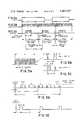
- FIGS. 2A-2Cillustrate a graphical representation of several signal waveforms appearing at selected locations in the remote control system of the present invention.
- FIGS. 3A-3Eillustrate, in various degrees of expansion, the pulse coded control signals utilized in the present invention.
- Remote control system 10includes a keyboard 12 having a plurality of user operated push buttons 15 arranged in a matrix format by means of which control inputs are entered.
- the user initiated control inputsare provided to a controller integrated circuit 14 via a plurality of lines X1 through X8 connected to respective rows of push buttons 15 and lines Y1 through Y4 connected to respective columns of push buttons 15.
- Controller IC 14decodes the keyboard generated inputs and converts these commands to a pulse code modulated (PCM) output which is provided to a light emitting diode (LED) 16.
- PCMpulse code modulated
- LED 16emits a PCM control signal in the infrared spectrum which is transmitted to and received by a photo diode 18 which, in turn, transmits the coded control signals to a controlled device 20 where the input signals are decoded and used to regulate various functions of the controlled device.
- a controlled device 20For simplicity, only one controlled device 20 is shown in FIG. 1 although in practice the present invention is intended to be utilized with a plurality of such controlled devices, each having a plurality of selectively variable operating parameters.
- keyboard 12includes an 8 ⁇ 4 matrix keyboard which includes 32 single-pole, single-throw switches each indicated as a push button control 15. This matrix of user operated switches is connected to a controller IC 14 by means of 12 input/output lines which are designated as X1-X8 and Y1-Y4.
- the 32 commands which can be generated by means of the 8 ⁇ 4 matrix keyboard 12are encoded into multi-bit pulse code modulated (PCM) words which are described in detail below.
- PCMpulse code modulated
- the keyboard switches 15 on keyboard 12are scanned in a bi-directional manner by means of outputs from the X- and Y- ports 22, 24. This is accomplished by means of a plurality of flip-flops (not shown) connected to each of the row and column conducting lines and two logic gates, the inputs to which are provided by the respective, grouped row and column flip-flops.
- the systemfirst scans in one direction by means of outputting signals via lines X1-X8 to detect the column of the user input provided to Y-ports 24 via one of the lines Y1-Y4.
- the aforementioned flip-flopsare then timed-out and the direction of the sensing signal is reversed by the oscillator timing circuitry 34.
- An output signalis provided via Y-ports 24 on lines Y1-Y4, with a particular input signal via one of lines X1-X8 providing the row location, or X component, of the user engaged push button switch 15.
- the row and column location of the user engaged push button switch 15is provided to the X- and Y- ports 22, 24, respectively, in the form of a function code.
- a function codedesignates the particular operating parameter controlled by the engagement of a particular push button switch 15.
- first and second pluralities of flip-flopsare connected to respective row and column conducting lines and to a respective pair of logic gates
- Each pair of logic gatesincludes the combination of a NOR gate and a differentiating circuit, such as a monostable multivibrator.
- the oscillator timing circuit 34 in the controller IC 14operates for a predetermined period, which in a preferred embodiment of the present invention is 180 milliseconds, as shown in FIG. 2B.
- the key closure signalis provided via one of the Y-ports 24 and the X-Y key detect decoder 28 and associated conductors 23, 25 to the oscillator 34.
- This input signalinitiates the oscillator operation as shown in FIG. 2B.
- Oscillator timing circuit 34is driven by a ceramic resonator 36 which, in turn, is energized by oscillator 1 and oscillator 2 drive inputs.
- Oscillator 34is coupled to the X- and Y- ports 22, 24, the X-Y key detect decoder 28, the Y5 decoder 30, the code group generator 32, the bit pattern generator 38, the shift register 40, and the output driver 42.
- Oscillator timing circuit 34provides appropriate operational timing sequence signals to these various components for processing of the digital signals provided via the X- and Y- ports 22, 24 to the various pulse decoding components in the controller IC 14.
- a ground, or reference voltage, terminal 27is incorporated in the controller IC 14 as well as an input power supply terminal Vcc 29 for energizing the controller integrated circuit 14.
- the output on lines X1-X8is a logic high.
- the input state on lines Y1-Y4is a logic low and oscillator timing circuit 34 is in the OFF state.
- the state of the output signal on line Y5which is described in greater detail below, is a high impedance state.
- the key scan sequenceis initiated upon key closure as shown in FIGS. 2A-2C. Following key closure, a logic high signal is provided from lines X1-X8 through the closed key switch to one of the lines Y1-Y4, depending upon which key 15 is engaged.
- the Y inputis provided to oscillator timing circuit 34 as previously described and initiates the operation thereof.
- the 180 millisecond signal processing cycle shown in FIG. 2Cis initiated.
- the signal processing cyclebegins with a key debounce time interval (40 milliseconds). Engagement of a push button control 15 must extend at least over this predetermined time interval for verification of a control input in order to make the system less sensitive to spurious inputs.
- the input provided on one of the lines Y1-Y4not only initiates oscillator 34 operation, but also after the 40 millisecond key debounce period, stores in the X-Y key detect decoder 28 the Y, or column, location of the selected key via line 23. Following the storage of the Y, or column, information in the X-Y decoder 28, lines X1-X8 are switched to an input, or logic low, state.
- a Y5 port 26which is connected to the Y5 decoder 30. As shown in FIG. 1 in dotted line form, the Y5 port 26 may be wired to any one of the X1-X8 conductors. If it is so connected to one of these input/output lines, when the X1-X8 conductors transition from an output to an input state by means of a change in the logic level of the signal applied thereto, the Y5 port 26 will similarly transition to an output state. When this occurs, the X-port 22 will be responsive to an input signal provided thereto and provide this input signal to the Y5 decoder 30 via line 35 for processing this information therein.
- the Y-5 port 26When the X input is provided to the Y-5 decoder 30 via line 35 from one of the X-ports 22, the Y-5 port 26 is turned off (transitions to the high impedance state) and the Y1-Y4 ports 24 then transition to the output state for a reverse scanning of the keyboard 12. This sequential scanning is sensed by the X-ports 22 and loaded into the X-Y decoder 28 via line 31. Thus, the row location of the selected key is then provided to the X-Y decoder 28 for processing therein.
- the selection of a given push button control 15 on keyboard 12will result in the storage of the X-Y matrix location of that push button in the X-Y key detect decoder 28 and the storage of the selected code group in the Y5 decoder 30.
- the coded signals representing the X-Y matrix locationtogether comprise the function code.
- the signal provided via line 35 from one of the X-ports 22 to the Y5 decoderrepresents the code group selected and ultimately defines the start bit and 6th and 7th bits of transmitted information.
- the Y5 decoder 30is enabled to store and decode information input by the X-ports 22 via line 35 by means of the input signal provided thereto from the Y5 port 26 via line 33.
- Receipt of this signal by the Y5 decoder 30initiates the processing of the code group selection signal therein.
- the selection of a single push buttonpermits the detection and storage of signals representing the device which is to be controlled, or the code group selection signal, as well as the function code for regulating a particular operating parameter of that device.
- the configuration of these various input control signals and their processing in the controller IC 14will be described in detail presently.
- a 140 millisecond time intervaloccurs as provided by oscillator timing circuit 34 after which the system is set to the initial idle condition again and the key closure/detection process is repeated. A new key scan sequence is initiated even if the same key is still depressed. This is shown in FIGS. 2A-2C.
- the X-Y key detect decoder 28receives eight X inputs from the X-ports 22, although for simplicity this connection is shown as a single conductor 31.
- the X-Y decoder 28includes conventional logic circuitry which determines when an X input is a logic high and generates a binary number corresponding to that input signal.
- the X-Y decoder 28receives four inputs from the Y-ports 24 corresponding to the Y1-Y4 conductors. This decoder similarly generates a binary number representing the respective Y input and combines the two binary numbers thus generated in response to the X and Y port values and provides a composite digital signal representing the matrix push button control selected to the bit pattern generator 38 via conductor 37.
- the coded signal thus provided from the X-Y key detect decoder 28represents a push button key closure corresponding to one of 32 possible codes.
- the Y5 decoder 30is similar to the X-Y key detect decoder 28 in organization and operation in that it also receives binary input signals from the X-ports 22 via line 35 and an enabling signal from the Y5 port 26 via line 33.
- the bit pattern generator 38is responsive to the digital signals provided thereto from the X-Y key detect decoder 28 and the Y5 decoder 30 via lines 37 and 39 respectively. Bit pattern generator 38 is thus responsive to a binary signal representing the X-Y coordinates of the selected push button control provided thereto via line 37 which determines the 5 data bits of information, or the function controlled, and the selected operating code group information provided thereto via line 39, which determines the start bit and 6th and 7th bits.
- the pulsed configuration of a typical control signal generated by the bit pattern generator 38is shown in FIG. 3D and is discussed in detail below. These two digital signals are thus combined by the bit pattern generator 38 which generates an output which is then loaded into a ripple counter, or shift register, 40 via the conductors 41.
- Bit pattern generator 38similar to the X-Y key detect decoder 28 and the Y5 decoder 30, is comprised of conventional digital logic circuitry which combines inputs provided by the two aforementioned decoders in generating function control and code group information and providing said information to the shift register 40.
- the bit pattern generator 38may be of conventional design and indeed may be accomplished in a large variety of design configurations. The specific design of the bit pattern generator 38 does not form a part of the present invention and is not further described herein.
- the X-Y key detect decoder 28 and the Y5 decoder 30may be of conventional digital logic circuitry design in receiving and processing the function and code group signals and generating coded digital signals in response thereto and providing the signals to the bit pattern generator 38. Since the operation of and the functions performed by these decoders may be accomplished in a great variety of ways known to those skilled in the design of digital logic circuitry, the specific configuration of these decoders will not be further described herein.
- An X-Y mask programmable discriminator 29is coupled to and responsive to an output signal from the X-Y decoder 28.
- This mask programmable discriminator 29establishes the code group selected in response to an output from the X-Y decoder 28 representing a particular selector key 15 engagement if the Y5 port 26 is not connected to one of the X-ports 22.
- This mode of operationis described in detail below.
- the Y5 decoder 30is enabled by an output from the Y5 port 26 which is coupled to one of the X-ports 22, the Y5 decoder 30 provides a logic high to one terminal of one of the OR gates 54A-54H. The particular OR gate receiving this signal is determined by the contents of the Y5 decoder 30.
- the Y5 decoder 30similarly provides one logic high input signal to NOR gate 50 which consequently outputs a logic low signal to all of the AND gates 52A-52H which, in turn, prevents any signals coming from the X-Y discriminator 29 from reaching OR gates 54A-54H.
- the Y5 decoder 30 with the Y5 port coupled to one of the X-ports 22accesses the code group generator 32 in reading a predetermined code therefrom which determines the start bit and the 6th and 7th bits, or the code group, of the output pulse train.
- the oscillator timing circuit 34is coupled to and provides timing for the X-Y key detect decoder 28 and the Y5 decoder 30 for the clocking of signals from the respective X- and Y-ports 22, 24. Once the key closure signals are clocked into the respective decoders, oscillator timing circuit 34 clocks the signals through the respective blocks and into the bit pattern generator 38 to which it is also coupled in providing proper signal timing thereto. This allows the bit pattern generator 38 to receive the function control and code group signals from the respective blocks in proper sequence so as to generate and transmit the resulting composite signal to the shift register 40 via lines 41.
- Shift register 40receives a clocking signal from oscillator timing circuit 34 permitting it to clock the information loaded from the bit pattern generator 38 and to generate the output pulse pattern within a predetermined time period as determined by the aforementioned clocking signal.
- the output of the shift register 40is then provided to the output driver 42 which, in turn, drives a light emitting diode 16, or a plurality of such light emitting diodes, for generating an electromagnetic wave.
- the transmitted electromagnetic wavewhich is representative of the function control and code group signals selected by means of keyboard 12, is received by a photo-sensitive diode 18, the output of which is provided to the controlled device 20 in a conventional manner.
- the present inventionenvisions the use of a plurality of such controlled devices although, for simplicity's sake, only one such device 20 is shown in FIG. 1.
- the present inventionis not limited to the use of the infrared spectrum for propagating the control signals, but will operate equally as well with an acoustic type of signal transmission system.
- the generation of pulse coded control signals and their transmission by whatever propagation medium selected and the subsequent reception and post-processing of these signals in regulating the controlled devicemay be conventional in nature, does not form a part of the present invention, and therefore will not be described in greater detail.
- FIGS. 3A-3Ethere is shown the pulsed configuration of a typical control signal produced in a preferred embodiment of the present invention.
- the basic element of a control signalis a pulse of width A which actually is a series of 20 bursts each having a period of 25 microseconds. Each bit is comprised of a series of pulses and is 500 microseconds in length.
- Table Ishows the values of various control signal parameters for an oscillator clocking rate of 640 KHz where the output driver 42 is clocked at an ON/OFF rate of 40 KHz.
- 20 clock pulses Awould occur within the time period of 500 microseconds.
- the pulse width Aequals the inter-pulse time B, which is also 500 microseconds.
- each bitis 5.6 milliseconds in length and that a logical 0 value is represented by an initial single pulse followed by a two pulse grouping, while a logical 1 is represented by an initial two pulse grouping followed by a single pulse.
- the period Drepresents the time interval during which a pulse code signal is generated in response to a user initiated keyboard control input.
- Frepresents the key debounce period following the key scan time interval for key closure.
- the present inventioncontemplates the use of a pulse code signal using five basic bits which can be supplemented by means of additional 6th and 7th bits. This expanded code is available by means of a single control input is described in detail in the following paragraphs. Referring to Table II, there is shown a coding scheme which is used in a preferred embodiment of the present invention.
- Each code grouprepresents one of the X1-X8 input/output lines.
- the Y5 port 26is coupled to one of these X1-X8 conductors as shown in Table II for generating a control word of varying length.
- code groups 1 and 2are represented by a five bit word while code groups 3 and 4 are represented by six bit words and code groups 5, 6, 7 and 8 are represented by seven bit words.
- the configuration of the sixth and seventh bits of the various code groupsare also shown in Table II.
- the pulse coded signalsare ternary digital signals in which the 6th and 7th bits assume either a logic 1 state, a logic 0 state, or no bit is transmitted in this position.
- a command wordincludes at least 5 data bits and may vary in length from five to seven bits. It should also be noted that for code group 1, two start bits are utilized to initiate a control word while in code groups 2-8 a single start bit is utilized.
- a double or single pulse start bitis an important feature of the present invention in that the remote control system used in some currently available remote control systems utilized solely in combination with a television receiver employ a two pulse start bit.
- a television receiver remote control systemis the infrared remote control system utilized in the System III chassis television receiver manufactured by Zenith Radio Corp.
- the code depicted in Table IIis compatible with both an available, conventional television receiver remote control system, namely by using code group 1, while providing for an expanded control device capability by using code groups 2-8.
- This capabilityis furthermore available without incorporating additional controls in the remote control keyboard 12, without adding additional data lines between the keyboard 12 and the controller IC 14, and without incorporating a microcomputer in the remote controller IC 14 which would result in substantially increased system complexity and cost.
- the system as thus far describedenvisions the hard wiring of the Y5 port 26 to one of the X1-X8 input/output lines, as shown in dotted line form in FIG. 1. However, the system may also be implemented by not coupling the Y5 port to any of the X1-X8 lines. If the Y5 port 26 is not connected to any of the X1-X8 lines, the system defaults upon selection of a push button control 15 to a mode in which the code group is selected by means of information stored in the mask programmable X-Y discriminator 29 which is enabled via line 21 by the X-Y decoder 28.
- the Y5 decoderreceives no input from the X-ports 22 and after a short time interval determined by oscillator timing block 34 consequently provides an output of 0 to NOR gate 50 and to each of the OR gates 54A-54H.
- the 8-input NOR gate 50then provides a logic 1 to one input terminal of each of the AND gates 52A-52H thus enabling outputs from the X-Y discriminator 29 to select the code group.
- the X-Y discriminator 29in response to an input signal from the X-Y decoder 28 then provides a logic 1 to one of the AND gates 52A-52H, which output signal is then transmitted to a corresponding OR gate 54A-54H, thence to the code group generator 32, and then to the bit pattern generator 38.
- the Y5 decoder 30provides no code group information and the system defaults to a condition where code group information is provided by the X-Y discriminator 29, which has been mask programmed to provide code groups based on the location of the key selected.
- the code group output signal from the X-Y discriminator 29is initiated in response to a timing signal received by the discriminator 29 from the oscillator timing circuit 34.
- this code group signalis provided from the discriminator 29 to the code group generator 32 only after a predetermined time period following start up of the oscillator timing circuit 34 and then only if a group code signal is not provided to the Y5 decoder 30 from one of the X-ports 22.
- the output group code signalis determined in the code group generator 32 by the output of the X-Y discriminator 29 in a manner similar to that in the case of the processing of the Y5 decoder output signal with the addition that the address code information is determined by the particular X-Y matrix location.
- any of the eight code groupsmay be selected in the code group generator 32 as assigned by the X-Y key location mask programmed in the X-Y discriminator 29 and provided to the bit pattern generator 38 in response to the selection of a given push button control 15.
- a connection made from the Y5 port 26 to any X1-X8 pinoverrides the mask option available from the X-Y discriminator 29 and results in the generation of a code in accordance with Table II.
- the mask option previously describedpermits the selection of any 32 of the 256 available codes on an "as desired" basis such that the codes from various code groups may be intermixed and stored in the code group generator 32 and recalled therefrom as previously described.
- the start bits and the 6th and 7th bitsmay be intermixed such that the same 5 bit function code as designated by a particular X-Y key input may be used to control several devices depending upon the code selected from the code group generator 32. This permits the remote control system of the present invention to control several devices without a separate mode control switch for individually addressing those controlled devices.
Landscapes
- Physics & Mathematics (AREA)
- General Physics & Mathematics (AREA)
- Engineering & Computer Science (AREA)
- Automation & Control Theory (AREA)
- Selective Calling Equipment (AREA)
Abstract
Description
TABLE I ______________________________________ DIMENSION DURATION ______________________________________ A 500 μSEC. B 500 μSEC. C 5.6 MSEC. D 57.5 MSEC. E 179.2 MSEC. F 40.0 MSEC. ______________________________________
TABLE II ______________________________________ EXTERNAL HARDWARE TOTAL CODE CON- DATA START 6TH 7TH GROUP NECTION BITS BITS BIT BIT ______________________________________ 1 Y5-X1 5 2None None 2 Y5-X2 5 1None None 3 Y5-X3 6 1 0None 4 Y5-X4 6 1 1None 5 Y5-X5 7 1 0 0 6 Y5-X6 7 1 1 0 7 Y5-X7 7 1 0 1 8 Y5-X8 7 1 1 1 ______________________________________
TABLE III ______________________________________ KEY- DECI- BOARD MAL FUNCTION CODE CLOS- EQUI- PATTERNFUNCTION URES VALENT 1 2 3 4 5 6 7 ______________________________________Special # 3 X1-Y1 0 0 0 0 0 0 0 PR. CH. DN X2-Y1 1 0 0 0 0 1 Vol. Down X3-Y1 2 0 0 0 1 0 Auto Off X4-Y1 3 0 0 0 1 1 Min X5-Y1 4 0 0 1 0 0 0 Hour X6-Y1 5 0 0 1 0 1 0 All CH. Up X7-Y1 6 0 0 1 1 0 0 All Ch. Dn X8-Y1 7 0 0 1 1 1 0 X1-Y2 8 0 1 0 0 0 0 PR. CH. UP X2-Y2 9 0 1 0 0 1 Vol. Up X3-Y2 10 0 1 0 1 0 Mute/Priv. X4-Y2 11 0 1 0 1 1 Auto On X5-Y2 12 0 1 1 0 0 Auto On X6-Y2 13 0 1 1 0 1 0 Momentary X7-Y2 14 0 1 1 1 0 On/Off Screen On X8-Y2 15 0 1 1 1 1 0 X1-Y3 16 1 0 0 0 0 1 X2-Y3 17 1 0 0 0 1 2 X3-Y3 18 1 0 0 1 0 3 X4-Y3 19 1 0 0 1 1 4 X5-Y3 20 1 0 1 0 0 5 X6-Y3 21 1 0 1 0 1 6 X7-Y3 22 1 0 1 1 0 7 X8-Y3 23 1 0 1 1 1 8 X1-Y4 24 1 1 0 0 0 9 X2-Y4 25 1 1 0 0 1 Phone X3-Y4 26 1 1 0 1 0 0Spcl 2 X4-Y4 27 1 1 0 1 1 0 Ent/Recall X5-Y4 28 1 1 1 0 0 Mute Clr X6-Y4 29 1 1 1 0 1 0 X7-Y4 30 1 1 1 1 0 0 X8-Y4 31 1 1 1 1 1 0 ______________________________________
Claims (12)
Priority Applications (1)
| Application Number | Priority Date | Filing Date | Title |
|---|---|---|---|
| US06/367,827US4482947A (en) | 1982-04-12 | 1982-04-12 | Multi-function, multi-unit remote control system and method therefor |
Applications Claiming Priority (1)
| Application Number | Priority Date | Filing Date | Title |
|---|---|---|---|
| US06/367,827US4482947A (en) | 1982-04-12 | 1982-04-12 | Multi-function, multi-unit remote control system and method therefor |
Publications (1)
| Publication Number | Publication Date |
|---|---|
| US4482947Atrue US4482947A (en) | 1984-11-13 |
Family
ID=23448784
Family Applications (1)
| Application Number | Title | Priority Date | Filing Date |
|---|---|---|---|
| US06/367,827Expired - LifetimeUS4482947A (en) | 1982-04-12 | 1982-04-12 | Multi-function, multi-unit remote control system and method therefor |
Country Status (1)
| Country | Link |
|---|---|
| US (1) | US4482947A (en) |
Cited By (72)
| Publication number | Priority date | Publication date | Assignee | Title |
|---|---|---|---|---|
| EP0165386A1 (en)* | 1984-04-26 | 1985-12-27 | Heidelberger Druckmaschinen Aktiengesellschaft | Method and storage system for the storage of control data for press actuators |
| US4626847A (en)* | 1983-12-27 | 1986-12-02 | Zenith Electronics Corporation | Remote control transmitter system |
| US4703359A (en)* | 1985-05-30 | 1987-10-27 | Nap Consumer Electronics Corp. | Universal remote control unit with model identification capability |
| US4774511A (en)* | 1985-05-30 | 1988-09-27 | Nap Consumer Electronics Corp. | Universal remote control unit |
| GB2204426A (en)* | 1987-05-08 | 1988-11-09 | Hauni Werke Koerber & Co Kg | Remote control apparatus for machine tools |
| US4788542A (en)* | 1986-04-23 | 1988-11-29 | Yuhshin Co., Ltd. | Remote control device for vehicle locks |
| US4792972A (en)* | 1986-08-19 | 1988-12-20 | Scientific-Atlanta, Inc. | Remote programming of CATV channel authorization unit |
| US4802114A (en)* | 1986-02-07 | 1989-01-31 | General Electric Company | Programmable remote control transmitter |
| EP0249111A3 (en)* | 1986-06-09 | 1989-03-22 | Stein Gmbh | Device for converting switch codings into specified functions |
| US4817203A (en)* | 1986-06-02 | 1989-03-28 | Sony Corporation | Remote control system |
| US4833467A (en)* | 1986-02-28 | 1989-05-23 | Mitsubishi Denki Kabushiki Kaisha | Data transmission system |
| FR2624891A1 (en)* | 1987-07-14 | 1989-06-23 | Tokai Ind Sewing Machine | Embroidering machine |
| US4864550A (en)* | 1984-03-07 | 1989-09-05 | U.S. Philips Corporation | Remote control equipment for use with an audio system |
| US4905279A (en)* | 1988-02-26 | 1990-02-27 | Nec Home Electronics Ltd. | Learning-functionalized remote control receiver |
| US4914428A (en)* | 1986-05-30 | 1990-04-03 | Mitsubishi Denki Kaushiki | Digital remote control transmission apparatus |
| US4959645A (en)* | 1988-12-23 | 1990-09-25 | Balz Richard C | Remotely activated television swivel base |
| US4965557A (en)* | 1982-07-29 | 1990-10-23 | Nokia Unterhaltungselektronik | Interactive control of entertainment electronics apparatus |
| JPH0329495A (en)* | 1989-06-26 | 1991-02-07 | Matsushita Electric Ind Co Ltd | Wireless remote control data transmission method |
| EP0341689A3 (en)* | 1988-05-13 | 1991-05-22 | Moeller GmbH | Control apparatus |
| US5138649A (en)* | 1990-11-16 | 1992-08-11 | General Instrument Corporation | Portable telephone handset with remote control |
| US5237319A (en)* | 1987-05-22 | 1993-08-17 | Pioneer Electronic Corporation | Remote control device with learning function |
| US5243430A (en)* | 1991-07-24 | 1993-09-07 | Mitsubishi Electronics America, Inc. | Remote control apparatus and method for omnidirectional signal transmission |
| US5271584A (en)* | 1992-03-02 | 1993-12-21 | General Railway Signal | Pulse code railway signalling system |
| WO1994003017A1 (en)* | 1992-07-17 | 1994-02-03 | Voice Powered Technology International, Inc. | Universal remote control device |
| US5414761A (en)* | 1987-10-14 | 1995-05-09 | Universal Electronics Inc. | Remote control system |
| US5442340A (en)* | 1988-12-05 | 1995-08-15 | Prince Corporation | Trainable RF transmitter including attenuation control |
| US5450841A (en)* | 1993-05-18 | 1995-09-19 | Gmi Holding, Inc. | Multi-function remote control system for gas fireplace |
| US5451953A (en)* | 1993-02-03 | 1995-09-19 | Thomson Consumer Electronics, Inc. | Programmable remote control unit without extra key for configuration |
| US5455716A (en)* | 1990-08-14 | 1995-10-03 | Prince Corporation | Vehicle mirror with electrical accessories |
| US5457448A (en)* | 1993-08-03 | 1995-10-10 | Sony Electronics, Inc. | Self-standing mini remote commander |
| US5479155A (en)* | 1988-12-05 | 1995-12-26 | Prince Corporation | Vehicle accessory trainable transmitter |
| US5515052A (en)* | 1987-10-14 | 1996-05-07 | Universal Electronics Inc. | Universal remote control with function synthesis |
| US5552917A (en)* | 1987-10-14 | 1996-09-03 | Universal Electronics Inc. | Remote control |
| US5579496A (en)* | 1991-04-02 | 1996-11-26 | U.S. Phillips Corporation | Method and apparatus for processing control instructions received from multiple sources connected to a communication bus |
| US5583485A (en)* | 1988-12-05 | 1996-12-10 | Prince Corporation | Trainable transmitter and receiver |
| US5614885A (en)* | 1988-12-05 | 1997-03-25 | Prince Corporation | Electrical control system for vehicle options |
| US5619190A (en)* | 1994-03-11 | 1997-04-08 | Prince Corporation | Trainable transmitter with interrupt signal generator |
| US5661804A (en)* | 1995-06-27 | 1997-08-26 | Prince Corporation | Trainable transceiver capable of learning variable codes |
| US5686903A (en)* | 1995-05-19 | 1997-11-11 | Prince Corporation | Trainable RF transceiver |
| US5699055A (en)* | 1995-05-19 | 1997-12-16 | Prince Corporation | Trainable transceiver and method for learning an activation signal that remotely actuates a device |
| US5699065A (en)* | 1996-01-16 | 1997-12-16 | Stanley Home Automation | Remote control transmitter and method of operation |
| US5699054A (en)* | 1995-05-19 | 1997-12-16 | Prince Corporation | Trainable transceiver including a dynamically tunable antenna |
| US5793300A (en)* | 1993-03-15 | 1998-08-11 | Prince Corporation | Trainable RF receiver for remotely controlling household appliances |
| US5802467A (en)* | 1995-09-28 | 1998-09-01 | Innovative Intelcom Industries | Wireless and wired communications, command, control and sensing system for sound and/or data transmission and reception |
| US5831555A (en)* | 1996-05-10 | 1998-11-03 | Industrial Technology Research Institute | Keyboard encoding system actuated by opening and closing of keyboard cover |
| US5872562A (en)* | 1985-05-30 | 1999-02-16 | U.S. Philips Corporation | Universal remote control transmitter with simplified device identification |
| US5898397A (en)* | 1996-01-16 | 1999-04-27 | Stanley Home Automation | Remote control transmitter and method of operation |
| EP0928626A1 (en)* | 1998-01-12 | 1999-07-14 | Toymax Inc. | Remotely controlled toy in a point of sale package |
| US6094238A (en)* | 1996-12-30 | 2000-07-25 | Mitsubishi Digital Electronics America, Inc. | Apparatus and method for time base compensated infrared data transmission |
| US6256019B1 (en) | 1999-03-30 | 2001-07-03 | Eremote, Inc. | Methods of using a controller for controlling multi-user access to the functionality of consumer devices |
| US20020194587A1 (en)* | 2001-03-13 | 2002-12-19 | Lampton David P. | Enhanced communication, monitoring and control system |
| US20030084352A1 (en)* | 2001-10-30 | 2003-05-01 | Schwartz Jeffrey D. | Appliance security model system and method |
| US6587067B2 (en) | 1987-10-14 | 2003-07-01 | Universal Electronics Inc. | Universal remote control with macro command capabilities |
| US6603488B2 (en)* | 1997-06-25 | 2003-08-05 | Samsung Electronics Co., Ltd. | Browser based command and control home network |
| US6636157B1 (en)* | 1993-05-14 | 2003-10-21 | Sony Corporation | Wireless remote control system for controlling an appliance |
| US6636273B1 (en) | 2001-02-01 | 2003-10-21 | Savvy Frontiers Patent Trust | Remote control dedicated keybutton for confirming tuner setting of a TV set to a specific channel setting |
| US6757001B2 (en) | 1999-03-30 | 2004-06-29 | Research Investment Network, Inc. | Method of using physical buttons in association with a display to access and execute functions available through associated hardware and software |
| US20050024185A1 (en)* | 2003-07-30 | 2005-02-03 | Lear Corporation | Remote control automatic appliance activation |
| US20050024230A1 (en)* | 2003-07-30 | 2005-02-03 | Lear Corporation | Programmable vehicle-based appliance remote control |
| US6931231B1 (en) | 2002-07-12 | 2005-08-16 | Griffin Technology, Inc. | Infrared generator from audio signal source |
| US7054361B1 (en)* | 2000-05-31 | 2006-05-30 | Thomson Licensing | Method and apparatus for enhancing an infrared signal protocol |
| US20060148456A1 (en)* | 2003-07-30 | 2006-07-06 | Lear Corporation | User-assisted programmable appliance control |
| US7116242B2 (en) | 2002-11-27 | 2006-10-03 | Lear Corporation | Programmable transmitter and receiver including digital radio frequency memory |
| US7120430B2 (en) | 2003-07-30 | 2006-10-10 | Lear Corporation | Programmable interoperable appliance remote control |
| US7135957B2 (en) | 2001-12-19 | 2006-11-14 | Lear Corporation | Universal garage door operating system and method |
| US7183941B2 (en) | 2003-07-30 | 2007-02-27 | Lear Corporation | Bus-based appliance remote control |
| US7183940B2 (en) | 2003-07-30 | 2007-02-27 | Lear Corporation | Radio relay appliance activation |
| US20070135939A1 (en)* | 2000-04-25 | 2007-06-14 | Georgia Tech Research Corporation | Adaptive control system having hedge unit and related apparatus and methods |
| US7269416B2 (en) | 2003-07-30 | 2007-09-11 | Lear Corporation | Universal vehicle based garage door opener control system and method |
| US7812739B2 (en) | 2003-07-30 | 2010-10-12 | Lear Corporation | Programmable appliance remote control |
| US20100309535A1 (en)* | 2009-06-08 | 2010-12-09 | Reald Inc. | Shutter-glass eyewear control |
| CN117850323A (en)* | 2024-01-18 | 2024-04-09 | 重庆宁来科贸有限公司 | Control circuit and control telephone |
Citations (8)
| Publication number | Priority date | Publication date | Assignee | Title |
|---|---|---|---|---|
| US4010423A (en)* | 1975-06-26 | 1977-03-01 | Zenith Radio Corporation | Multi-function remote control ic |
| US4177453A (en)* | 1977-10-25 | 1979-12-04 | Zenith Radio Corporation | Digital remote control system with improved noise immunity |
| US4231031A (en)* | 1977-02-09 | 1980-10-28 | U.S. Philips Corporation | Remote control system capable of transmitting the information with the aid of an infra red beam using PPM or an ultrasonic beam using PDM |
| US4246611A (en)* | 1977-06-21 | 1981-01-20 | Texas Instruments Incorporated | Digital control system and a method of transmitting control data in such a system |
| US4291385A (en)* | 1973-12-17 | 1981-09-22 | Hewlett-Packard Company | Calculator having merged key codes |
| US4318130A (en)* | 1978-08-09 | 1982-03-02 | The Magnavox Company | Microprocessor control system for television receivers |
| US4338632A (en)* | 1980-10-06 | 1982-07-06 | Zenith Radio Corporation | Remote control system for television monitors |
| US4356509A (en)* | 1981-03-12 | 1982-10-26 | Zenith Radio Corporation | Microcomputer-controlled television/telephone system and method therefore |
- 1982
- 1982-04-12USUS06/367,827patent/US4482947A/ennot_activeExpired - Lifetime
Patent Citations (8)
| Publication number | Priority date | Publication date | Assignee | Title |
|---|---|---|---|---|
| US4291385A (en)* | 1973-12-17 | 1981-09-22 | Hewlett-Packard Company | Calculator having merged key codes |
| US4010423A (en)* | 1975-06-26 | 1977-03-01 | Zenith Radio Corporation | Multi-function remote control ic |
| US4231031A (en)* | 1977-02-09 | 1980-10-28 | U.S. Philips Corporation | Remote control system capable of transmitting the information with the aid of an infra red beam using PPM or an ultrasonic beam using PDM |
| US4246611A (en)* | 1977-06-21 | 1981-01-20 | Texas Instruments Incorporated | Digital control system and a method of transmitting control data in such a system |
| US4177453A (en)* | 1977-10-25 | 1979-12-04 | Zenith Radio Corporation | Digital remote control system with improved noise immunity |
| US4318130A (en)* | 1978-08-09 | 1982-03-02 | The Magnavox Company | Microprocessor control system for television receivers |
| US4338632A (en)* | 1980-10-06 | 1982-07-06 | Zenith Radio Corporation | Remote control system for television monitors |
| US4356509A (en)* | 1981-03-12 | 1982-10-26 | Zenith Radio Corporation | Microcomputer-controlled television/telephone system and method therefore |
Non-Patent Citations (2)
| Title |
|---|
| A Pulse Position Modulation Transmission System for Remote Control of a TV Set., H. J. Casier, H. J. de Man, C. Matthijs, pp. 801 808, IEEE Journal of Solid State Circuits, vol. SC 11, No. 6, Dec. 1976.* |
| A Pulse Position Modulation Transmission System for Remote Control of a TV Set., H. J. Casier, H. J. de Man, C. Matthijs, pp. 801-808, IEEE Journal of Solid State Circuits, vol. SC-11, No. 6, Dec. 1976. |
Cited By (93)
| Publication number | Priority date | Publication date | Assignee | Title |
|---|---|---|---|---|
| US4965557A (en)* | 1982-07-29 | 1990-10-23 | Nokia Unterhaltungselektronik | Interactive control of entertainment electronics apparatus |
| US4626847A (en)* | 1983-12-27 | 1986-12-02 | Zenith Electronics Corporation | Remote control transmitter system |
| US4864550A (en)* | 1984-03-07 | 1989-09-05 | U.S. Philips Corporation | Remote control equipment for use with an audio system |
| EP0165386A1 (en)* | 1984-04-26 | 1985-12-27 | Heidelberger Druckmaschinen Aktiengesellschaft | Method and storage system for the storage of control data for press actuators |
| US5872562A (en)* | 1985-05-30 | 1999-02-16 | U.S. Philips Corporation | Universal remote control transmitter with simplified device identification |
| US4774511A (en)* | 1985-05-30 | 1988-09-27 | Nap Consumer Electronics Corp. | Universal remote control unit |
| US4703359A (en)* | 1985-05-30 | 1987-10-27 | Nap Consumer Electronics Corp. | Universal remote control unit with model identification capability |
| AU592991B2 (en)* | 1985-05-30 | 1990-02-01 | North American Philips Consumer Electronics Corp. | Universal remote control unit |
| US4802114A (en)* | 1986-02-07 | 1989-01-31 | General Electric Company | Programmable remote control transmitter |
| US4833467A (en)* | 1986-02-28 | 1989-05-23 | Mitsubishi Denki Kabushiki Kaisha | Data transmission system |
| US4788542A (en)* | 1986-04-23 | 1988-11-29 | Yuhshin Co., Ltd. | Remote control device for vehicle locks |
| US4914428A (en)* | 1986-05-30 | 1990-04-03 | Mitsubishi Denki Kaushiki | Digital remote control transmission apparatus |
| US4817203A (en)* | 1986-06-02 | 1989-03-28 | Sony Corporation | Remote control system |
| EP0249111A3 (en)* | 1986-06-09 | 1989-03-22 | Stein Gmbh | Device for converting switch codings into specified functions |
| US4792972A (en)* | 1986-08-19 | 1988-12-20 | Scientific-Atlanta, Inc. | Remote programming of CATV channel authorization unit |
| GB2204426A (en)* | 1987-05-08 | 1988-11-09 | Hauni Werke Koerber & Co Kg | Remote control apparatus for machine tools |
| US5237319A (en)* | 1987-05-22 | 1993-08-17 | Pioneer Electronic Corporation | Remote control device with learning function |
| FR2624891A1 (en)* | 1987-07-14 | 1989-06-23 | Tokai Ind Sewing Machine | Embroidering machine |
| US5689353A (en)* | 1987-10-14 | 1997-11-18 | Universal Electronics Inc. | Remote control with two-way data coupling |
| US5552917A (en)* | 1987-10-14 | 1996-09-03 | Universal Electronics Inc. | Remote control |
| US5515052A (en)* | 1987-10-14 | 1996-05-07 | Universal Electronics Inc. | Universal remote control with function synthesis |
| US5953144A (en)* | 1987-10-14 | 1999-09-14 | Universal Electronics Inc. | Upgradeable remote control device |
| US6587067B2 (en) | 1987-10-14 | 2003-07-01 | Universal Electronics Inc. | Universal remote control with macro command capabilities |
| US5414761A (en)* | 1987-10-14 | 1995-05-09 | Universal Electronics Inc. | Remote control system |
| US4905279A (en)* | 1988-02-26 | 1990-02-27 | Nec Home Electronics Ltd. | Learning-functionalized remote control receiver |
| EP0341689A3 (en)* | 1988-05-13 | 1991-05-22 | Moeller GmbH | Control apparatus |
| US5708415A (en)* | 1988-12-05 | 1998-01-13 | Prince Corporation | Electrical control system for vehicle options |
| US5614891A (en)* | 1988-12-05 | 1997-03-25 | Prince Corporation | Vehicle accessory trainable transmitter |
| US5691848A (en)* | 1988-12-05 | 1997-11-25 | Prince Corporation | Electrical control system for vehicle options |
| US5699044A (en)* | 1988-12-05 | 1997-12-16 | Prince Corporation | Electrical control system for vehicle options |
| US5661455A (en)* | 1988-12-05 | 1997-08-26 | Prince Corporation | Electrical control system for vehicle options |
| US5479155A (en)* | 1988-12-05 | 1995-12-26 | Prince Corporation | Vehicle accessory trainable transmitter |
| US5614885A (en)* | 1988-12-05 | 1997-03-25 | Prince Corporation | Electrical control system for vehicle options |
| US5442340A (en)* | 1988-12-05 | 1995-08-15 | Prince Corporation | Trainable RF transmitter including attenuation control |
| US5583485A (en)* | 1988-12-05 | 1996-12-10 | Prince Corporation | Trainable transmitter and receiver |
| US4959645A (en)* | 1988-12-23 | 1990-09-25 | Balz Richard C | Remotely activated television swivel base |
| JPH0329495A (en)* | 1989-06-26 | 1991-02-07 | Matsushita Electric Ind Co Ltd | Wireless remote control data transmission method |
| US5455716A (en)* | 1990-08-14 | 1995-10-03 | Prince Corporation | Vehicle mirror with electrical accessories |
| US5646701A (en)* | 1990-08-14 | 1997-07-08 | Prince Corporation | Trainable transmitter with transmit/receive switch |
| US5138649A (en)* | 1990-11-16 | 1992-08-11 | General Instrument Corporation | Portable telephone handset with remote control |
| US5579496A (en)* | 1991-04-02 | 1996-11-26 | U.S. Phillips Corporation | Method and apparatus for processing control instructions received from multiple sources connected to a communication bus |
| US5243430A (en)* | 1991-07-24 | 1993-09-07 | Mitsubishi Electronics America, Inc. | Remote control apparatus and method for omnidirectional signal transmission |
| US5271584A (en)* | 1992-03-02 | 1993-12-21 | General Railway Signal | Pulse code railway signalling system |
| WO1994003017A1 (en)* | 1992-07-17 | 1994-02-03 | Voice Powered Technology International, Inc. | Universal remote control device |
| US5451953A (en)* | 1993-02-03 | 1995-09-19 | Thomson Consumer Electronics, Inc. | Programmable remote control unit without extra key for configuration |
| US5793300A (en)* | 1993-03-15 | 1998-08-11 | Prince Corporation | Trainable RF receiver for remotely controlling household appliances |
| US6636157B1 (en)* | 1993-05-14 | 2003-10-21 | Sony Corporation | Wireless remote control system for controlling an appliance |
| US5450841A (en)* | 1993-05-18 | 1995-09-19 | Gmi Holding, Inc. | Multi-function remote control system for gas fireplace |
| US5457448A (en)* | 1993-08-03 | 1995-10-10 | Sony Electronics, Inc. | Self-standing mini remote commander |
| US5619190A (en)* | 1994-03-11 | 1997-04-08 | Prince Corporation | Trainable transmitter with interrupt signal generator |
| US5627529A (en)* | 1994-03-11 | 1997-05-06 | Prince Corporation | Vehicle control system with trainable transceiver |
| US5699054A (en)* | 1995-05-19 | 1997-12-16 | Prince Corporation | Trainable transceiver including a dynamically tunable antenna |
| US5699055A (en)* | 1995-05-19 | 1997-12-16 | Prince Corporation | Trainable transceiver and method for learning an activation signal that remotely actuates a device |
| US5686903A (en)* | 1995-05-19 | 1997-11-11 | Prince Corporation | Trainable RF transceiver |
| US5661804A (en)* | 1995-06-27 | 1997-08-26 | Prince Corporation | Trainable transceiver capable of learning variable codes |
| US5802467A (en)* | 1995-09-28 | 1998-09-01 | Innovative Intelcom Industries | Wireless and wired communications, command, control and sensing system for sound and/or data transmission and reception |
| US5699065A (en)* | 1996-01-16 | 1997-12-16 | Stanley Home Automation | Remote control transmitter and method of operation |
| US5898397A (en)* | 1996-01-16 | 1999-04-27 | Stanley Home Automation | Remote control transmitter and method of operation |
| US5831555A (en)* | 1996-05-10 | 1998-11-03 | Industrial Technology Research Institute | Keyboard encoding system actuated by opening and closing of keyboard cover |
| US6094238A (en)* | 1996-12-30 | 2000-07-25 | Mitsubishi Digital Electronics America, Inc. | Apparatus and method for time base compensated infrared data transmission |
| US6603488B2 (en)* | 1997-06-25 | 2003-08-05 | Samsung Electronics Co., Ltd. | Browser based command and control home network |
| US6727826B1 (en) | 1998-01-12 | 2004-04-27 | Toymax Inc | Remotely controlled toy and wireless remote operable in a point of sale package |
| EP0928626A1 (en)* | 1998-01-12 | 1999-07-14 | Toymax Inc. | Remotely controlled toy in a point of sale package |
| US6011489A (en)* | 1998-01-12 | 2000-01-04 | Toymax Inc. | Remotely controlled toy and wireless remote operable in a point of sale package |
| US6906696B2 (en) | 1999-03-30 | 2005-06-14 | Research Investment Network, Inc. | Method of controlling multi-user access to the functionality of consumer devices |
| US20010030644A1 (en)* | 1999-03-30 | 2001-10-18 | Allport David E. | Method of controlling multi-user access to the functionality of consumer devices |
| US6256019B1 (en) | 1999-03-30 | 2001-07-03 | Eremote, Inc. | Methods of using a controller for controlling multi-user access to the functionality of consumer devices |
| US6757001B2 (en) | 1999-03-30 | 2004-06-29 | Research Investment Network, Inc. | Method of using physical buttons in association with a display to access and execute functions available through associated hardware and software |
| US20070135939A1 (en)* | 2000-04-25 | 2007-06-14 | Georgia Tech Research Corporation | Adaptive control system having hedge unit and related apparatus and methods |
| US7054361B1 (en)* | 2000-05-31 | 2006-05-30 | Thomson Licensing | Method and apparatus for enhancing an infrared signal protocol |
| US6636273B1 (en) | 2001-02-01 | 2003-10-21 | Savvy Frontiers Patent Trust | Remote control dedicated keybutton for confirming tuner setting of a TV set to a specific channel setting |
| US20020194587A1 (en)* | 2001-03-13 | 2002-12-19 | Lampton David P. | Enhanced communication, monitoring and control system |
| US20030084352A1 (en)* | 2001-10-30 | 2003-05-01 | Schwartz Jeffrey D. | Appliance security model system and method |
| US7135957B2 (en) | 2001-12-19 | 2006-11-14 | Lear Corporation | Universal garage door operating system and method |
| US7167076B2 (en) | 2001-12-19 | 2007-01-23 | Lear Corporation | Universal garage door operating system and method |
| US6931231B1 (en) | 2002-07-12 | 2005-08-16 | Griffin Technology, Inc. | Infrared generator from audio signal source |
| US7116242B2 (en) | 2002-11-27 | 2006-10-03 | Lear Corporation | Programmable transmitter and receiver including digital radio frequency memory |
| US7183941B2 (en) | 2003-07-30 | 2007-02-27 | Lear Corporation | Bus-based appliance remote control |
| US20070190993A1 (en)* | 2003-07-30 | 2007-08-16 | Lear Corporation | User-assisted programmable appliance control |
| US7161466B2 (en) | 2003-07-30 | 2007-01-09 | Lear Corporation | Remote control automatic appliance activation |
| US20060148456A1 (en)* | 2003-07-30 | 2006-07-06 | Lear Corporation | User-assisted programmable appliance control |
| US20050024230A1 (en)* | 2003-07-30 | 2005-02-03 | Lear Corporation | Programmable vehicle-based appliance remote control |
| US7183940B2 (en) | 2003-07-30 | 2007-02-27 | Lear Corporation | Radio relay appliance activation |
| US20050024185A1 (en)* | 2003-07-30 | 2005-02-03 | Lear Corporation | Remote control automatic appliance activation |
| US7120430B2 (en) | 2003-07-30 | 2006-10-10 | Lear Corporation | Programmable interoperable appliance remote control |
| US7269416B2 (en) | 2003-07-30 | 2007-09-11 | Lear Corporation | Universal vehicle based garage door opener control system and method |
| US7447498B2 (en) | 2003-07-30 | 2008-11-04 | Lear Corporation | User-assisted programmable appliance control |
| US7489922B2 (en) | 2003-07-30 | 2009-02-10 | Lear Corporation | User-assisted programmable appliance control |
| US7760071B2 (en) | 2003-07-30 | 2010-07-20 | Lear Corporation | Appliance remote control having separated user control and transmitter modules remotely located from and directly connected to one another |
| US7812739B2 (en) | 2003-07-30 | 2010-10-12 | Lear Corporation | Programmable appliance remote control |
| US7855633B2 (en) | 2003-07-30 | 2010-12-21 | Lear Corporation | Remote control automatic appliance activation |
| US20100309535A1 (en)* | 2009-06-08 | 2010-12-09 | Reald Inc. | Shutter-glass eyewear control |
| CN117850323A (en)* | 2024-01-18 | 2024-04-09 | 重庆宁来科贸有限公司 | Control circuit and control telephone |
Similar Documents
| Publication | Publication Date | Title |
|---|---|---|
| US4482947A (en) | Multi-function, multi-unit remote control system and method therefor | |
| US4412218A (en) | Remote control signal transmitter capable of setting custom codes individually alloted to a plurality of controlled instruments | |
| US4769643A (en) | Transmitter driver for programmable remote control transmitter | |
| US4626848A (en) | Programmable functions for reconfigurable remote control | |
| AU592991B2 (en) | Universal remote control unit | |
| US4623887A (en) | Reconfigurable remote control | |
| EP0320066B1 (en) | Data compression technique for reconfigurable remote control apparatus | |
| KR900007131B1 (en) | Programmable Remote Control Transmitter | |
| HK84996A (en) | Reconfigurable remote control apparatus | |
| US5128667A (en) | Wireless remote controller for outputting in seriatim an operation mode signal for each of a plurality of receiving devices | |
| JPS61111074A (en) | Television camera | |
| GB1570695A (en) | Remote control system | |
| US3987414A (en) | Digital remote control for electronic signal receivers | |
| US3631398A (en) | Tv remote control system | |
| US5059975A (en) | Control signal generation circuit for wireless remote control signal transmitter | |
| JPS62101771A (en) | Remote control type key operation apparatus | |
| US5212487A (en) | Apparatus and method for adaptive remote transmission | |
| KR0176830B1 (en) | Method for receiving a number of signals | |
| EP0553073A4 (en) | Universal remote control system | |
| JPH03196795A (en) | remote control device | |
| JPS59119995A (en) | Transmission circuit for remote control | |
| JP2677005B2 (en) | Remote control device | |
| JPS62130099A (en) | remote control device | |
| KR960004294B1 (en) | Learning Remote Control Wireless Phone | |
| JPH0632505B2 (en) | Remote control transmitter |
Legal Events
| Date | Code | Title | Description |
|---|---|---|---|
| AS | Assignment | Owner name:ZENITH ELECTRONICS CORPORATION 1000 MILWAUKEE AVE. Free format text:ASSIGNMENT OF ASSIGNORS INTEREST.;ASSIGNORS:ZATO, THOMAS J.;SKERLOS, PETER C.;REEL/FRAME:004279/0497 Effective date:19840702 | |
| STCF | Information on status: patent grant | Free format text:PATENTED CASE | |
| FEPP | Fee payment procedure | Free format text:PAYOR NUMBER ASSIGNED (ORIGINAL EVENT CODE: ASPN); ENTITY STATUS OF PATENT OWNER: LARGE ENTITY | |
| FPAY | Fee payment | Year of fee payment:4 | |
| FPAY | Fee payment | Year of fee payment:8 | |
| AS | Assignment | Owner name:FIRST NATIONAL BANK OF CHICAGO, THE Free format text:SECURITY INTEREST;ASSIGNOR:ZENITH ELECTRONICS CORPORATION A CORP. OF DELAWARE;REEL/FRAME:006187/0650 Effective date:19920619 | |
| AS | Assignment | Owner name:ZENITH ELECTRONICS CORPORATION Free format text:RELEASED BY SECURED PARTY;ASSIGNOR:FIRST NATIONAL BANK OF CHICAGO, THE (AS COLLATERAL AGENT).;REEL/FRAME:006243/0013 Effective date:19920827 | |
| FPAY | Fee payment | Year of fee payment:12 |