US4479557A - Method and apparatus for reducing field filter cake on sponge cores - Google Patents
Method and apparatus for reducing field filter cake on sponge coresDownload PDFInfo
- Publication number
- US4479557A US4479557AUS06/513,267US51326783AUS4479557AUS 4479557 AUS4479557 AUS 4479557AUS 51326783 AUS51326783 AUS 51326783AUS 4479557 AUS4479557 AUS 4479557A
- Authority
- US
- United States
- Prior art keywords
- fluid
- inner barrel
- well core
- core
- well
- Prior art date
- Legal status (The legal status is an assumption and is not a legal conclusion. Google has not performed a legal analysis and makes no representation as to the accuracy of the status listed.)
- Expired - Lifetime
Links
- 238000000034methodMethods0.000titleclaimsdescription21
- 239000012065filter cakeSubstances0.000titledescription7
- 239000012530fluidSubstances0.000claimsabstractdescription93
- 238000005553drillingMethods0.000claimsabstractdescription27
- 230000004044responseEffects0.000claimsabstractdescription13
- XLYOFNOQVPJJNP-UHFFFAOYSA-NwaterSubstancesOXLYOFNOQVPJJNP-UHFFFAOYSA-N0.000claimsdescription32
- 239000000463materialSubstances0.000claimsdescription22
- 238000007789sealingMethods0.000claimsdescription15
- 229920005830Polyurethane FoamPolymers0.000claimsdescription11
- 239000011496polyurethane foamSubstances0.000claimsdescription11
- 150000003839saltsChemical class0.000claimsdescription9
- 239000000126substanceSubstances0.000claimsdescription9
- 230000006835compressionEffects0.000claimsdescription6
- 238000007906compressionMethods0.000claimsdescription6
- 238000009738saturatingMethods0.000claimsdescription6
- HZAXFHJVJLSVMW-UHFFFAOYSA-N2-Aminoethan-1-olChemical compoundNCCOHZAXFHJVJLSVMW-UHFFFAOYSA-N0.000claimsdescription5
- 229920006395saturated elastomerPolymers0.000claimsdescription5
- 230000015572biosynthetic processEffects0.000claimsdescription4
- 238000011084recoveryMethods0.000claimsdescription4
- 238000010521absorption reactionMethods0.000claimsdescription3
- 239000006260foamSubstances0.000claimsdescription3
- 230000014759maintenance of locationEffects0.000claimsdescription3
- 239000002283diesel fuelSubstances0.000claimsdescription2
- 239000011148porous materialSubstances0.000claims15
- 230000001050lubricating effectEffects0.000claims8
- CURLTUGMZLYLDI-UHFFFAOYSA-NCarbon dioxideChemical compoundO=C=OCURLTUGMZLYLDI-UHFFFAOYSA-N0.000claims2
- 229910002092carbon dioxideInorganic materials0.000claims1
- 239000001569carbon dioxideSubstances0.000claims1
- 229920002635polyurethanePolymers0.000claims1
- 239000004814polyurethaneSubstances0.000claims1
- 238000000926separation methodMethods0.000claims1
- 239000011162core materialSubstances0.000description79
- 239000007789gasSubstances0.000description10
- 230000008569processEffects0.000description3
- 230000000740bleeding effectEffects0.000description2
- 230000000694effectsEffects0.000description2
- 238000000605extractionMethods0.000description2
- 238000003780insertionMethods0.000description2
- 230000037431insertionEffects0.000description2
- 238000005259measurementMethods0.000description2
- 230000035699permeabilityEffects0.000description2
- 230000002378acidificating effectEffects0.000description1
- 230000004075alterationEffects0.000description1
- XAGFODPZIPBFFR-UHFFFAOYSA-NaluminiumChemical compound[Al]XAGFODPZIPBFFR-UHFFFAOYSA-N0.000description1
- 229910052782aluminiumInorganic materials0.000description1
- 238000004891communicationMethods0.000description1
- 150000001875compoundsChemical class0.000description1
- 238000010276constructionMethods0.000description1
- 239000000356contaminantSubstances0.000description1
- 230000007423decreaseEffects0.000description1
- 230000001419dependent effectEffects0.000description1
- 238000010586diagramMethods0.000description1
- 238000005470impregnationMethods0.000description1
- 238000009533lab testMethods0.000description1
- 239000000314lubricantSubstances0.000description1
- QSHDDOUJBYECFT-UHFFFAOYSA-NmercuryChemical compound[Hg]QSHDDOUJBYECFT-UHFFFAOYSA-N0.000description1
- 229910052753mercuryInorganic materials0.000description1
- 230000000149penetrating effectEffects0.000description1
- 230000000717retained effectEffects0.000description1
- 239000002689soilSubstances0.000description1
- 238000006467substitution reactionMethods0.000description1
- 238000012546transferMethods0.000description1
- 238000009736wettingMethods0.000description1
Images

Classifications
- E—FIXED CONSTRUCTIONS
- E21—EARTH OR ROCK DRILLING; MINING
- E21B—EARTH OR ROCK DRILLING; OBTAINING OIL, GAS, WATER, SOLUBLE OR MELTABLE MATERIALS OR A SLURRY OF MINERALS FROM WELLS
- E21B25/00—Apparatus for obtaining or removing undisturbed cores, e.g. core barrels or core extractors
- E21B25/08—Coating, freezing, consolidating cores; Recovering uncontaminated cores or cores at formation pressure
Definitions
- This inventionpertains in general to apparatus for well coring and, more particularly, to well coring apparatus utilizing an absorbant sponge for containing the subterranean fluid in the core.
- Sponge coringcomprises disposing a high porosity sponge on the interior surface of the inner barrel of the well coring apparatus. The core is then forced into the inner barrel with the sponge disposed about the sides thereof. The oil and/or gas contained in the core then "bleeds" into the sponge thereby retaining an accurate profile of the oil along the longitudinal axis of the core.
- the present invention disclosed and claimed hereincomprises a method and apparatus for recovery of subterranean fluid.
- the apparatusincludes a well coring apparatus for boring a well containing the subterranean fluid.
- a containeris associated with the coring apparatus for receiving and containing the well core for later retrieval.
- An absorbant memberis disposed on the inner walls of the container and positioned adjacent the well core for absorbing the subterranean fluid that bleeds from the well core.
- the containeris sealed from the external environment of the bore hole with a rupturable seal on the receiving end thereof.
- a reciprocating memberis disposed within the well coring apparatus for breaking this rupturable seal in response to the forming of the core such that a core enters the container relatively unobstructed.
- the sealed containerhas two open ends with the rupturable seal formed at the receiving end thereof and a check valve disposed on the other end thereof for allowing efferent flow only.
- the reciprocating memberis a piston having a planar surface for contacting the well core and a conical shaped surface on the opposite side thereof with an apex for rupturing the rupturable seal.
- the sealed containeris filled with a fluid for reducing the field filter cake that surrounds the core as it is being formed. This fluid is displaced from the absorbant member as fluid from the core bleeds therebetween.
- a method for recovering the subterranean fluidcomprises disposing an absorbant material in the inner barrel of the well coring apparatus on the walls thereof and then sealing the inner barrel from the external environment of the well core.
- the fluidis disposed within the container containing the absorbant material and then the inner barrel is disposed into the well with the well coring apparatus.
- the seal to the inner barrelis broken in response to the forming of the well core such that the well core enters the inner barrel and the absorbant material in the inner barrel is relatively uncontaminated, the fluid contained therein preventing field filter cake that is disposed around the formed well core from impeding fluid exchange from the well core to the absorbant material.
- a method for forming the well core and retrieving the subterranean fluid contained thereinincludes impregnating the absorbant member with a fluid at a high pressure prior to placing the inner barrel into the well coring apparatus.
- a vacuumis first drawn on the inner barrel containing the absorbant member and then the fluid is disposed in the inner barrel at a high pressure, thereby impregnating the material of the absorbant member with the fluid. Impregnation of the absorbant member with the fluid reduces field filter cake problems.
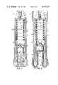
- FIG. 1illustrates a cross-sectional view of the sponge coring apparatus of the present invention
- FIG. 2illustrates a cross-sectional view of the sponge coring apparatus of the present invention disposed in a subterranean well with the piercer penetrating the rupturable seal;
- FIG. 3illustrates a cross-sectional view of the sponge coring apparatus of the present invention with the formed core fully disposed within the inner barrel.
- FIG. 1there is illustrated a cross-sectional view of a well coring apparatus 10.
- the well coring apparatus 10includes an outer barrel 12 that has a bit sub 14 disposed on the end thereof.
- the bit sub 14is utilized to couple a coring bit 16 to the outer barrel 12.
- the coring bit 16, the bit sub 14 and the outer barrel 12are co-rotatable by an external drilling apparatus (not shown) for drilling a core.
- an external drilling apparatusnot shown
- the description of the coring procedureis described in U.S. Pat. No. 4,312,414, issued to the present Applicant, the body of which is incorporated herein by reference.
- An inner barrel 18is disposed within the outer barrel 12 such that an annular channel 20 is formed therebetween.
- This annular channel 20allows drilling fluids to pass therethrough to the coring bit 16.
- the inner barrel 18is stationary with respect to rotation of the outer barrel 12 and is designed for receiving the core that is formed during the coring process.
- This inner barrel 18has a receiving end for receiving the well core and an exhaust end for exhausting material contained within the inner barrel 18 as the core progresses upward therethrough.
- a seal housing 22is threadedly disposed on the receiving end of the inner barrel 18 through which the core must pass before it enters the inner barrel 18.
- the seal housing 22has a rupturable diaphragm 24 disposed over the open end thereof. In order for the core to enter the seal housing 22 and the inner barrel 18, this diaphragm 24 must be ruptured.
- a core catcher bowl 26is threadedly engaged with the seal housing 22.
- a core catcher 28is disposed in the core catcher bowl 26 adjacent the opening thereof.
- the core catcher bowl 26has a receiving end 30 for receiving the core to be formed.
- the annular channel 20is disposed between the wall formed by the outer barrel 12, the core bit sub 14 and the coring bit 16 and the wall formed by the inner barrel 18, the seal housing 22 and the core catcher bowl 26.
- a piercer 32is disposed in the core catcher bowl 26 and spaced from the sides thereof by a cylindrical insert 34.
- the piercer 32is essentially a piston having a planar surface 36 for contacting the core being formed and a conical surface 38 disposed diametrically opposite the planar surface 36.
- the planar surface 36is essentially perpendicular to the longitudinal axis of the overall apparatus 10.
- the conical surface 38has the apex thereon oriented proximate to the longitudinal axis of the inner barrel 18 for traversal therealong.
- the piercer 32is operable to pierce the rupturable diaphragm 24 in response to pressure applied to the planar surface 36 by the core being formed.
- the diameter of the piercer 32is slightly larger than the upper portion of the core catcher 28 such that reciprocation downward through the coring bit 16 is prevented. Therefore, the core that is formed with the apparatus 10 is also slightly smaller in diameter than the piercer 32.
- the end of the inner barrel 18 opposite that attached to the seal housing 22has a flow tube 40 threadedly attached thereto.
- the flow tube 40has an orifice 42 disposed axially therethrough.
- fluidalso flows around the flow tube 40 into the annular channel 20 for passage to the surface of the coring bit 16.
- a check valve seat 44is disposed in the orifice 42 of the flow tube 40.
- the seat 44has an orifice 46 axially disposed therethrough to allow communication between the orifice 42 and the interior of the inner barrel 18.
- a check valve ball 48is disposed in the seat 44 for impeding afferent flow to the inner barrel 18. However, the ball 48 is operable to allow afferent flow from the interior of the inner barrel 18 when the pressure interior thereto exceeds the pressure in the orifice 42 of the flow tube 40.
- the check valve ball 48 and the seat 44form an overall check valve 49.
- a cylindrical sponge 50is disposed on the interior walls of a cylindrical support member or liner 52.
- the liner 52is dimensioned to slideably fit within the inner barrel 18 adjacent the walls thereof.
- the liner 52is fabricated from aluminum and the sponge 50 is fabricated from polyurethane foam. The use and construction of this foam is disclosed in U.S. Pat. No. 4,312,414, issued to the present Applicant.
- the sponge 50is dimensioned to define a bore through the middle thereof for receiving the core. Pressure of the drilling fluid in the orifice 42 of the check valve 49 seals the ball 48 and prevents drilling mud from entering the interior of the inner barrel 18.
- the rupturable diaphragm 24prevents entrance of drilling mud from the opposite end thereof thereby resulting in a sealed chamber. As will be described hereinbelow, this chamber is filled with a fluid 54.
- FIG. 2there is illustrated a cross-sectional diagram of the apparatus 10 disposed in a subterranean well 56 and partially forming a core 58.
- the piercer 32is illustrated at a position wherein the rupturable diaphragm 24 has just been ruptured.
- FIG. 3illustrates the position wherein the core has passed through the rupturable diaphragm and into the interior of the inner barrel 18 for contact with the sponge 50.
- the piercer 32advances upward into the inner barrel 18 until it contacts the upper end of the inner barrel 18.
- the fluid 54 contained in the interior of the inner barrel 18passes upward through the orifice 46 with a small portion passing downward around the core 58 and out past the coring bit 16.
- the piercer 32as described above, has a diameter that is slightly larger than the diameter of the core 58. In this manner, the piercer 32 forms a hole through the diaphragm 24 that is larger than the core 58 itself, thereby preventing disruption of the outer surface of the core 58. This is important in that it is the surface of the core 58 through which the oil and subterranean fluid contained therein must pass to the sponge 50.
- the inner diameter of the seal housing 22is dimensioned to be larger than that of the core 58, thereby allowing adequate room for the edges of the ruptured diaphragm 24 to be removed from the path of the core 58.
- the interior diameter thereofis dimensioned less than the diameter of the core 58 to form a tight fit therewith.
- the sponge 50is relatively compressible in that it has a high porosity, thereby allowing a certain degree of compression.
- the sealed inner barrel 18allows location of the apparatus 10 within the bore hole without allowing drilling mud to penetrate the interior of the inner barrel 18. If the drilling mud were allowed to contact the surfaces of the absorbant member 50, there is a high probability that some of the drilling mud would "cake” on the surfaces thereof. This caking would substantially impair “bleeding" of oil or subterranean fluid from the core 58 to the absorbed member 50 for retention therein. Therefore, the use of a sealed inner barrel 18 reduces the amount of drilling mud that cakes on the surface of the core 58 prior to drilling the core itself.
- the inner barrel with the sponge 50is lowered into the subterranean well 56 at depths that result in a pressure much higher than that of atmospheric pressure.
- the sponge 50is normally of the open celled type which, when subjected to increasing pressure, has a tendency to compress when the open cells are filled with a gas such as air. If the sponge 50 is inserted into the inner barrel 18 on the surface with the open cells therein filled with air, insertion into the well 58 at a higher pressure results in compression of the individual cells in the overall sponge 50. This compression results in reduced volume for absorption of mobile oil and an increased space between the surfaces of the sponge 50 and the core 58.
- the fit between the core 58 and the sponge 50is relatively "tight" in order to, first, provide a contact between the surfaces to enhance the transfer of mobile oil from the core 58 to the sponge 50 and, second, to prevent the drilling mud that is caked around the core 58 to be disposed between the sponge 50 and the core 58.
- the sponge 50is a polyurethane foam with a very high porosity of around 70%.
- the permeability of this foamis approximately two darcies.
- field salt wateris utilized within the inner barrel 18. Since polyurethane foam by its nature is highly oil wettable, it resists saturation by field salt water. To overcome this resistance, the inner barrel 18 with the polyurethane foam in place is evacuated with a vacuum pump prior to placing the inner barrel 18 into the outer barrel 12. After the vacuum is effected (approximately ten inches of mercury) the polyurethane foam is then flooded with the field salt water to between 300 and 500 pounds per square inch (psi) pressure. This saturates the polyurethane foam. This wetting of the polyurethane foam is done just prior to the coring operation.
- the fluidAfter saturation, the fluid is removed from the bore formed by the interior of the sponge 50 and the inner barrel 18. Although the fluid is drained therefrom, the open celled structure of the sponge 50 is permeated by the fluid. After draining, the inner barrel 18 is inserted into the outer barrel 12 with the diaphragm 24 in place. The fluid 54 is then disposed within the interior of the inner barrel 18 through the check valve 49 with the ball 48 removed and the ball 48 then inserted to effect the seal.
- Field salt wateris utilized in a situation where the oil saturation is desired since oil will displace this water from the sponge 50.
- the field salt water disposed in the open celled structure of the sponge 50prevents collapse of these structures where the pressure increases after insertion of the apparatus 10 into the well 56.
- the drilling mudis water based, preferably field salt water, which is readily distinguishable from the oil absorbed by the sponge 50, thereby facilitating analysis for the percentage of mobile oil contained in the sponge 50.
- the mud that is used in drilling the wellis preferably oil based, but it may be any base that is readily distinguishable from the water contained in the core and that does not combine with the water to form a different compound.
- the sponge 50is saturated with high quality dry diesel oil. The procedure for saturating the polyurethane foam is the same as described above. This facilitates absorption of the water in the core which is readily distinguishable from the drilling fluid and the fluid contained in the sponge 50.
- C0 2 at the pressures existing at the bottom of the wellis normally in solution.
- the pressuredecreases, thereby allowing the C0 2 to come out of solution as a gas.
- this gasis allowed to escape and must be retained to measure the quantity thereof.
- the fluid utilized in the inner containeris monoethanolamine, which is a water soluble chemical with a great chemical affinity for acidic gases such as C0 2 and/or H 2 S.
- any C0 2 that escapes from the coreis captured by the sponge 50 and can be analyzed as part of the overall analysis after retrieval of the sponge 50.
- the sponge 50is impregnated with the monoethanolamine as described above with reference to the field salt water.
- an apparatus for sponge coringthat utilizes a sealed inner barrel disposed within an outer well coring barrel.
- the inner barrelis sealed at one end with a rupturable diaphragm and at the other one with a check valve that allows efferent flow only.
- a spongeis disposed around the walls of the inner barrel for receiving the sponge and absorbing the subterranean fluids therefrom.
- a reciprocating pistonis disposed within the well coring apparatus between the coring bit and the rupturable diaphragm.
- the reciprocal piston or piercerhas a planar surface for contacting the core that is being formed and a conical shaped surface on the other side thereof.
- the apex of the conical shaped surfaceis operable to pierce the rupturable diaphragm upon contact therewith in response to the forming of the well core.
- a fluidis disposed in the sealed inner barrel to saturate the sponge disposed therein.
- the sealed inner barrelboth contains the fluid to saturate the sponge and also prevents drilling mud from entering the inner barrel prior to forming of the core.
Landscapes
- Geology (AREA)
- Life Sciences & Earth Sciences (AREA)
- Engineering & Computer Science (AREA)
- Mining & Mineral Resources (AREA)
- Geochemistry & Mineralogy (AREA)
- Environmental & Geological Engineering (AREA)
- General Life Sciences & Earth Sciences (AREA)
- Physics & Mathematics (AREA)
- Fluid Mechanics (AREA)
- Sampling And Sample Adjustment (AREA)
- Drilling Tools (AREA)
- Solid-Sorbent Or Filter-Aiding Compositions (AREA)
- Molds, Cores, And Manufacturing Methods Thereof (AREA)
- Preparation Of Clay, And Manufacture Of Mixtures Containing Clay Or Cement (AREA)
- Cold Cathode And The Manufacture (AREA)
- Cereal-Derived Products (AREA)
- Processing And Handling Of Plastics And Other Materials For Molding In General (AREA)
- Food-Manufacturing Devices (AREA)
Abstract
Description
Claims (34)
Priority Applications (7)
| Application Number | Priority Date | Filing Date | Title |
|---|---|---|---|
| US06/513,267US4479557A (en) | 1983-07-13 | 1983-07-13 | Method and apparatus for reducing field filter cake on sponge cores |
| EP84302058AEP0132020B1 (en) | 1983-07-13 | 1984-03-27 | Method and apparatus for reducing field filter cake on sponge cores |
| AT84302058TATE29760T1 (en) | 1983-07-13 | 1984-03-27 | METHOD AND APPARATUS FOR REDUCING FILTER CAKE IN A SPONGE CORE CONTAINER. |
| DE8484302058TDE3466267D1 (en) | 1983-07-13 | 1984-03-27 | Method and apparatus for reducing field filter cake on sponge cores |
| AU26237/84AAU556415B2 (en) | 1983-07-13 | 1984-03-29 | Absorbant member for core bit |
| NO842853ANO842853L (en) | 1983-07-13 | 1984-07-12 | PROCEDURE AND DEVICE FOR THE REDUCTION OF A FIELD CORE FIELD FILTER CAKE |
| US06/661,893US4598777A (en) | 1983-07-13 | 1984-10-17 | Method and apparatus for preventing contamination of a coring sponge |
Applications Claiming Priority (1)
| Application Number | Priority Date | Filing Date | Title |
|---|---|---|---|
| US06/513,267US4479557A (en) | 1983-07-13 | 1983-07-13 | Method and apparatus for reducing field filter cake on sponge cores |
Related Child Applications (1)
| Application Number | Title | Priority Date | Filing Date |
|---|---|---|---|
| US06/661,893Continuation-In-PartUS4598777A (en) | 1983-07-13 | 1984-10-17 | Method and apparatus for preventing contamination of a coring sponge |
Publications (1)
| Publication Number | Publication Date |
|---|---|
| US4479557Atrue US4479557A (en) | 1984-10-30 |
Family
ID=24042538
Family Applications (1)
| Application Number | Title | Priority Date | Filing Date |
|---|---|---|---|
| US06/513,267Expired - LifetimeUS4479557A (en) | 1983-07-13 | 1983-07-13 | Method and apparatus for reducing field filter cake on sponge cores |
Country Status (6)
| Country | Link |
|---|---|
| US (1) | US4479557A (en) |
| EP (1) | EP0132020B1 (en) |
| AT (1) | ATE29760T1 (en) |
| AU (1) | AU556415B2 (en) |
| DE (1) | DE3466267D1 (en) |
| NO (1) | NO842853L (en) |
Cited By (25)
| Publication number | Priority date | Publication date | Assignee | Title |
|---|---|---|---|---|
| US4598777A (en)* | 1983-07-13 | 1986-07-08 | Diamond Oil Well Drilling Company | Method and apparatus for preventing contamination of a coring sponge |
| US4638872A (en)* | 1985-04-01 | 1987-01-27 | Diamond Oil Well Drilling Company | Core monitoring device |
| US4651835A (en)* | 1984-10-01 | 1987-03-24 | Eastman Christensen Company | Core catcher for use with an hydraulically displaced inner tube in a coring tool |
| US4716974A (en)* | 1986-07-21 | 1988-01-05 | Eastman Christensen Co | Method and apparatus for coring with an in situ core barrel sponge |
| US5360074A (en)* | 1993-04-21 | 1994-11-01 | Baker Hughes, Incorporated | Method and composition for preserving core sample integrity using an encapsulating material |
| US5439065A (en)* | 1994-09-28 | 1995-08-08 | Western Atlas International, Inc. | Rotary sidewall sponge coring apparatus |
| US5482123A (en)* | 1993-04-21 | 1996-01-09 | Baker Hughes Incorporated | Method and apparatus for pressure coring with non-invading gel |
| US5546798A (en)* | 1995-05-12 | 1996-08-20 | Baker Hughes Incorporated | Method and composition for preserving core sample integrity using a water soluble encapsulating material |
| WO1997026439A1 (en)* | 1996-01-15 | 1997-07-24 | Dresser Industries, Inc. | Core sampling method and core sampler therefor |
| WO1997026441A1 (en)* | 1996-01-15 | 1997-07-24 | Baroid Technology, Inc. | Fluid lubricant for a core sample and use thereof |
| US6216804B1 (en) | 1998-07-29 | 2001-04-17 | James T. Aumann | Apparatus for recovering core samples under pressure |
| US6283228B2 (en) | 1997-01-08 | 2001-09-04 | Baker Hughes Incorporated | Method for preserving core sample integrity |
| WO2002040824A2 (en) | 2000-11-14 | 2002-05-23 | Baker Hughes Incorporated | Apparatus and methods for sponge coring |
| US6695075B2 (en)* | 2000-05-10 | 2004-02-24 | Eijkelkamp Agrisearch Equipment B.V. | Soil sampler |
| US20150021096A1 (en)* | 2013-07-18 | 2015-01-22 | Baker Hughes Incorporated | Coring tools and methods for making coring tools and procuring core samples |
| US9217306B2 (en) | 2011-10-03 | 2015-12-22 | National Oilwell Varco L.P. | Methods and apparatus for coring |
| WO2016022383A1 (en)* | 2014-08-07 | 2016-02-11 | Halliburton Energy Services, Inc. | Cleaning and separating fluid and debris from core samples and coring systems |
| US9506307B2 (en) | 2011-03-16 | 2016-11-29 | Corpro Technologies Canada Ltd. | High pressure coring assembly and method |
| CN107355190A (en)* | 2017-04-28 | 2017-11-17 | 河南理工大学 | A kind of primary-secondary drill device for fixed point sampling |
| CN107503698A (en)* | 2017-09-19 | 2017-12-22 | 哈尔滨工业大学 | A kind of lunar soil drilling coring mechanism with guide ring |
| RU182812U1 (en)* | 2018-06-13 | 2018-09-04 | Акционерное общество "Всероссийский научно-исследовательский институт гидротехники имени Б.Е. Веденеева" | Device for extracting core from a well |
| US10072471B2 (en) | 2015-02-25 | 2018-09-11 | Baker Hughes Incorporated | Sponge liner sleeves for a core barrel assembly, sponge liners and related methods |
| US10584550B2 (en) | 2013-09-13 | 2020-03-10 | Halliburton Energy Services, Inc. | Sponge pressure equalization system |
| US10968711B2 (en) | 2018-01-11 | 2021-04-06 | Baker Hughes, Age Company, Llc | Shifting tool having puncture device, system, and method |
| CN115788341A (en)* | 2022-09-09 | 2023-03-14 | 四川大学 | Film-forming fidelity coring device while drilling in lunar-base extreme environment |
Citations (13)
| Publication number | Priority date | Publication date | Assignee | Title |
|---|---|---|---|---|
| US1815391A (en)* | 1929-09-13 | 1931-07-21 | Universal Engineering Company | Core drill with auxiliary reamer |
| US1853581A (en)* | 1930-05-17 | 1932-04-12 | John M Schmissrauter | Method and apparatus for scavenging core drills |
| US1857693A (en)* | 1929-10-07 | 1932-05-10 | Harry J Quintrell | Core barrel having core receptacle |
| US1859950A (en)* | 1930-07-03 | 1932-05-24 | John A Zublin | Core catcher |
| US1895001A (en)* | 1930-09-19 | 1933-01-24 | George A Macready | Core drill |
| US2264449A (en)* | 1939-04-12 | 1941-12-02 | Standard Oil Dev Co | Method and apparatus for coring |
| US2703697A (en)* | 1950-12-15 | 1955-03-08 | Robert D Walker | Process and apparatus for well coring |
| US2779195A (en)* | 1952-04-10 | 1957-01-29 | Simon Karl | Device for subsoil testing and taking of specimens |
| US2789790A (en)* | 1956-06-13 | 1957-04-23 | Ii John H Kirby | Core drilling apparatus |
| US3064742A (en)* | 1958-09-05 | 1962-11-20 | Jersey Prod Res Co | Obtaining unaltered core samples |
| US3207240A (en)* | 1961-10-31 | 1965-09-21 | Tiefbohr Messdienst Leutert & | Apparatus for the drilling of and the protection of drill cores in deep-welldrilling operations |
| US3454117A (en)* | 1968-01-16 | 1969-07-08 | Exxon Production Research Co | Obtaining unaltered core samples of subsurface earth formations |
| US4312414A (en)* | 1980-05-23 | 1982-01-26 | Diamond Oil Well Drilling Company | Method and apparatus for obtaining saturation data from subterranean formations |
Family Cites Families (6)
| Publication number | Priority date | Publication date | Assignee | Title |
|---|---|---|---|---|
| US2721055A (en)* | 1951-08-29 | 1955-10-18 | Leo D Madson | Core drill |
| US2880969A (en)* | 1955-06-01 | 1959-04-07 | Jersey Prod Res Co | Apparatus for obtaining unaltered cores |
| US2862691A (en)* | 1956-04-03 | 1958-12-02 | Jersey Prod Res Co | Coring bit assembly |
| US3146837A (en)* | 1958-12-30 | 1964-09-01 | Jersey Prod Res Co | System for obtaining trube core samples |
| US3515230A (en)* | 1968-07-09 | 1970-06-02 | Sprague & Henwood Inc | Heavy duty soil sampler |
| US3605920A (en)* | 1969-12-30 | 1971-09-20 | Texaco Inc | Core drilling apparatus with means to indicate amount of core in barrel |
- 1983
- 1983-07-13USUS06/513,267patent/US4479557A/ennot_activeExpired - Lifetime
- 1984
- 1984-03-27DEDE8484302058Tpatent/DE3466267D1/ennot_activeExpired
- 1984-03-27EPEP84302058Apatent/EP0132020B1/ennot_activeExpired
- 1984-03-27ATAT84302058Tpatent/ATE29760T1/ennot_activeIP Right Cessation
- 1984-03-29AUAU26237/84Apatent/AU556415B2/ennot_activeCeased
- 1984-07-12NONO842853Apatent/NO842853L/enunknown
Patent Citations (13)
| Publication number | Priority date | Publication date | Assignee | Title |
|---|---|---|---|---|
| US1815391A (en)* | 1929-09-13 | 1931-07-21 | Universal Engineering Company | Core drill with auxiliary reamer |
| US1857693A (en)* | 1929-10-07 | 1932-05-10 | Harry J Quintrell | Core barrel having core receptacle |
| US1853581A (en)* | 1930-05-17 | 1932-04-12 | John M Schmissrauter | Method and apparatus for scavenging core drills |
| US1859950A (en)* | 1930-07-03 | 1932-05-24 | John A Zublin | Core catcher |
| US1895001A (en)* | 1930-09-19 | 1933-01-24 | George A Macready | Core drill |
| US2264449A (en)* | 1939-04-12 | 1941-12-02 | Standard Oil Dev Co | Method and apparatus for coring |
| US2703697A (en)* | 1950-12-15 | 1955-03-08 | Robert D Walker | Process and apparatus for well coring |
| US2779195A (en)* | 1952-04-10 | 1957-01-29 | Simon Karl | Device for subsoil testing and taking of specimens |
| US2789790A (en)* | 1956-06-13 | 1957-04-23 | Ii John H Kirby | Core drilling apparatus |
| US3064742A (en)* | 1958-09-05 | 1962-11-20 | Jersey Prod Res Co | Obtaining unaltered core samples |
| US3207240A (en)* | 1961-10-31 | 1965-09-21 | Tiefbohr Messdienst Leutert & | Apparatus for the drilling of and the protection of drill cores in deep-welldrilling operations |
| US3454117A (en)* | 1968-01-16 | 1969-07-08 | Exxon Production Research Co | Obtaining unaltered core samples of subsurface earth formations |
| US4312414A (en)* | 1980-05-23 | 1982-01-26 | Diamond Oil Well Drilling Company | Method and apparatus for obtaining saturation data from subterranean formations |
Cited By (47)
| Publication number | Priority date | Publication date | Assignee | Title |
|---|---|---|---|---|
| US4598777A (en)* | 1983-07-13 | 1986-07-08 | Diamond Oil Well Drilling Company | Method and apparatus for preventing contamination of a coring sponge |
| US4651835A (en)* | 1984-10-01 | 1987-03-24 | Eastman Christensen Company | Core catcher for use with an hydraulically displaced inner tube in a coring tool |
| US4638872A (en)* | 1985-04-01 | 1987-01-27 | Diamond Oil Well Drilling Company | Core monitoring device |
| US4735269A (en)* | 1985-04-01 | 1988-04-05 | Diamond Oil Well Drilling Company | Core monitoring device with pressurized inner barrel |
| US4716974A (en)* | 1986-07-21 | 1988-01-05 | Eastman Christensen Co | Method and apparatus for coring with an in situ core barrel sponge |
| US5560438A (en)* | 1993-04-21 | 1996-10-01 | Baker Hughes Incorporated | Method and composition for preserving core sample integrity using an encapsulating material |
| US5360074A (en)* | 1993-04-21 | 1994-11-01 | Baker Hughes, Incorporated | Method and composition for preserving core sample integrity using an encapsulating material |
| US5482123A (en)* | 1993-04-21 | 1996-01-09 | Baker Hughes Incorporated | Method and apparatus for pressure coring with non-invading gel |
| US5439065A (en)* | 1994-09-28 | 1995-08-08 | Western Atlas International, Inc. | Rotary sidewall sponge coring apparatus |
| US5546798A (en)* | 1995-05-12 | 1996-08-20 | Baker Hughes Incorporated | Method and composition for preserving core sample integrity using a water soluble encapsulating material |
| WO1997026439A1 (en)* | 1996-01-15 | 1997-07-24 | Dresser Industries, Inc. | Core sampling method and core sampler therefor |
| WO1997026441A1 (en)* | 1996-01-15 | 1997-07-24 | Baroid Technology, Inc. | Fluid lubricant for a core sample and use thereof |
| BE1009968A5 (en)* | 1996-01-15 | 1997-11-04 | Dresser Ind | Core core and method for its implementation. |
| BE1009967A5 (en)* | 1996-01-15 | 1997-11-04 | Baroid Technology Inc | Lubricant fluid for carrot and use thereof. |
| US6164389A (en)* | 1996-01-15 | 2000-12-26 | Dresser Industries, Inc. | Core sampling method and core sampler therefor |
| US6283228B2 (en) | 1997-01-08 | 2001-09-04 | Baker Hughes Incorporated | Method for preserving core sample integrity |
| US6659204B2 (en) | 1998-07-29 | 2003-12-09 | Japan National Oil Corporation | Method and apparatus for recovering core samples under pressure |
| US6216804B1 (en) | 1998-07-29 | 2001-04-17 | James T. Aumann | Apparatus for recovering core samples under pressure |
| US6305482B1 (en) | 1998-07-29 | 2001-10-23 | James T. Aumann | Method and apparatus for transferring core sample from core retrieval chamber under pressure for transport |
| US6378631B1 (en) | 1998-07-29 | 2002-04-30 | James T. Aumann | Apparatus for recovering core samples at in situ conditions |
| US6230825B1 (en) | 1998-07-29 | 2001-05-15 | James T. Aumann | Apparatus for recovering core samples under pressure |
| US6695075B2 (en)* | 2000-05-10 | 2004-02-24 | Eijkelkamp Agrisearch Equipment B.V. | Soil sampler |
| US7231991B2 (en) | 2000-11-14 | 2007-06-19 | Baker Hughes Incorporated | Apparatus and methods for sponge coring |
| US20060169494A1 (en)* | 2000-11-14 | 2006-08-03 | Puymbroeck Luc V | Apparatus and methods for sponge coring |
| US6719070B1 (en) | 2000-11-14 | 2004-04-13 | Baker Hughes Incorporated | Apparatus and methods for sponge coring |
| US20040084216A1 (en)* | 2000-11-14 | 2004-05-06 | Puymbroeck Luc Van | Apparatus and methods for sponge coring |
| US20050133275A1 (en)* | 2000-11-14 | 2005-06-23 | Puymbroeck Luc V. | Apparatus and methods for sponge coring |
| US7004265B2 (en) | 2000-11-14 | 2006-02-28 | Baker Hughes Incorporated | Apparatus and methods for sponge coring |
| US20060169496A1 (en)* | 2000-11-14 | 2006-08-03 | Puymbroeck Luc V | Apparatus and methods for sponge coring |
| WO2002040824A3 (en)* | 2000-11-14 | 2003-02-06 | Baker Hughes Inc | Apparatus and methods for sponge coring |
| US7093676B2 (en) | 2000-11-14 | 2006-08-22 | Baker Hughes Incorporated | Apparatus and methods for sponge coring |
| WO2002040824A2 (en) | 2000-11-14 | 2002-05-23 | Baker Hughes Incorporated | Apparatus and methods for sponge coring |
| US7234547B2 (en) | 2000-11-14 | 2007-06-26 | Baker Hughes Incorporated | Apparatus and methods for sponge coring |
| US9506307B2 (en) | 2011-03-16 | 2016-11-29 | Corpro Technologies Canada Ltd. | High pressure coring assembly and method |
| US9217306B2 (en) | 2011-10-03 | 2015-12-22 | National Oilwell Varco L.P. | Methods and apparatus for coring |
| US20150021096A1 (en)* | 2013-07-18 | 2015-01-22 | Baker Hughes Incorporated | Coring tools and methods for making coring tools and procuring core samples |
| US9765585B2 (en)* | 2013-07-18 | 2017-09-19 | Baker Hughes Incorporated | Coring tools and methods for making coring tools and procuring core samples |
| US10584550B2 (en) | 2013-09-13 | 2020-03-10 | Halliburton Energy Services, Inc. | Sponge pressure equalization system |
| WO2016022383A1 (en)* | 2014-08-07 | 2016-02-11 | Halliburton Energy Services, Inc. | Cleaning and separating fluid and debris from core samples and coring systems |
| US9951574B2 (en) | 2014-08-07 | 2018-04-24 | Halliburton Energy Services, Inc. | Cleaning and separating fluid and debris from core samples and coring systems |
| US10072471B2 (en) | 2015-02-25 | 2018-09-11 | Baker Hughes Incorporated | Sponge liner sleeves for a core barrel assembly, sponge liners and related methods |
| CN107355190A (en)* | 2017-04-28 | 2017-11-17 | 河南理工大学 | A kind of primary-secondary drill device for fixed point sampling |
| CN107503698A (en)* | 2017-09-19 | 2017-12-22 | 哈尔滨工业大学 | A kind of lunar soil drilling coring mechanism with guide ring |
| US10968711B2 (en) | 2018-01-11 | 2021-04-06 | Baker Hughes, Age Company, Llc | Shifting tool having puncture device, system, and method |
| RU182812U1 (en)* | 2018-06-13 | 2018-09-04 | Акционерное общество "Всероссийский научно-исследовательский институт гидротехники имени Б.Е. Веденеева" | Device for extracting core from a well |
| CN115788341A (en)* | 2022-09-09 | 2023-03-14 | 四川大学 | Film-forming fidelity coring device while drilling in lunar-base extreme environment |
| CN115788341B (en)* | 2022-09-09 | 2024-05-10 | 四川大学 | A film-forming and fidelity coring device for extreme lunar environments |
Also Published As
| Publication number | Publication date |
|---|---|
| EP0132020A1 (en) | 1985-01-23 |
| EP0132020B1 (en) | 1987-09-16 |
| AU2623784A (en) | 1985-01-17 |
| ATE29760T1 (en) | 1987-10-15 |
| DE3466267D1 (en) | 1987-10-22 |
| NO842853L (en) | 1985-02-26 |
| AU556415B2 (en) | 1986-10-30 |
Similar Documents
| Publication | Publication Date | Title |
|---|---|---|
| US4479557A (en) | Method and apparatus for reducing field filter cake on sponge cores | |
| US4598777A (en) | Method and apparatus for preventing contamination of a coring sponge | |
| US4142594A (en) | Method and core barrel apparatus for obtaining and retrieving subterranean formation samples | |
| CA1276873C (en) | Formation fluid sampler | |
| US4312414A (en) | Method and apparatus for obtaining saturation data from subterranean formations | |
| Sayles et al. | A sampler for the in situ collection of marine sedimentary pore waters | |
| US6026900A (en) | Multiple liner method for borehole access | |
| US3111169A (en) | Continuous retrievable testing apparatus | |
| US5743343A (en) | Method and apparatus for fluid and soil sampling | |
| CA2848990C (en) | Pressure core barrel for retention of core fluids and related method | |
| US4258803A (en) | Core barrel for obtaining and retrieving subterranean formation samples | |
| US4631677A (en) | Method for determining the placement of perforations in a well casing | |
| US4502553A (en) | Sponge coring apparatus with reinforced sponge | |
| US10435974B2 (en) | Activation modules for obstructing entrances to inner barrels of coring tools and related coring tools and methods | |
| Barnes | An in situ interstitial water sampler for use in unconsolidated sediments | |
| CA1097328A (en) | Method and core barrel apparatus for obtaining and retrieving subterranean formation samples | |
| US6000481A (en) | Method and apparatus for environmental sampling | |
| US5421419A (en) | Method and apparatus for fluid and soil sampling | |
| US3152639A (en) | Methods and apparatus for testing wells | |
| Dickens et al. | The pressure core sampler (PCS) on ODP Leg 201: General operations and gas release | |
| US5477922A (en) | Method of evaluating the damage to the structure of rock surrounding a well | |
| CA1179531A (en) | Sealed bearing rotary rock bit assembly | |
| CN117307074A (en) | A kind of natural gas hydrate freezing core drilling tool and coring method | |
| JPH0617911Y2 (en) | Packer type groundwater sampling device | |
| EP0546062B1 (en) | A method and a device for zone impregnation of wood |
Legal Events
| Date | Code | Title | Description |
|---|---|---|---|
| AS | Assignment | Owner name:DIAMOND OIL WELL DRILLING COMPANY, MIDLAND, TX., A Free format text:ASSIGNMENT OF ASSIGNORS INTEREST.;ASSIGNOR:PARK, ARTHUR;REEL/FRAME:004152/0130 Effective date:19830705 Owner name:DIAMOND OIL WELL DRILLING COMPANY, MIDLAND, TX., A Free format text:ASSIGNMENT OF ASSIGNORS INTEREST;ASSIGNOR:PARK, ARTHUR;REEL/FRAME:004152/0130 Effective date:19830705 | |
| AS | Assignment | Owner name:DIAMOND OIL WELL DRILLING COMPANY MIDLAND TX A TX Free format text:ASSIGNMENT OF ASSIGNORS INTEREST.;ASSIGNORS:PARK, ARTHUR;WILSON, BOB T.;REEL/FRAME:004164/0229 Effective date:19830816 | |
| STCF | Information on status: patent grant | Free format text:PATENTED CASE | |
| FEPP | Fee payment procedure | Free format text:PAT HLDR NO LONGER CLAIMS SMALL ENT STAT AS SMALL BUSINESS (ORIGINAL EVENT CODE: LSM2); ENTITY STATUS OF PATENT OWNER: LARGE ENTITY Free format text:PAYOR NUMBER ASSIGNED (ORIGINAL EVENT CODE: ASPN); ENTITY STATUS OF PATENT OWNER: LARGE ENTITY | |
| AS | Assignment | Owner name:DIAMANT BOART-STRATABIT (USA) INC., 15955 WEST HAR Free format text:ASSIGNMENT OF ASSIGNORS INTEREST.;ASSIGNOR:DIAMOND OIL WELL DRILLING COMPANY;REEL/FRAME:004817/0569 Effective date:19880115 | |
| FPAY | Fee payment | Year of fee payment:4 | |
| FPAY | Fee payment | Year of fee payment:8 | |
| FPAY | Fee payment | Year of fee payment:12 | |
| AS | Assignment | Owner name:HALLIBURTON ENERGY SERVICES, INC., TEXAS Free format text:ASSIGNMENT OF ASSIGNORS INTEREST;ASSIGNOR:DRESSER INDUSTRIES, INC. (NOW KNOWN AS DII INDUSTRIES, LLC);REEL/FRAME:013727/0481 Effective date:20030113 |