US4478473A - Coupling nut for an electrical connector - Google Patents
Coupling nut for an electrical connectorDownload PDFInfo
- Publication number
- US4478473A US4478473AUS06/431,969US43196982AUS4478473AUS 4478473 AUS4478473 AUS 4478473AUS 43196982 AUS43196982 AUS 43196982AUS 4478473 AUS4478473 AUS 4478473A
- Authority
- US
- United States
- Prior art keywords
- sleeve
- coupling
- disposed
- shell
- ratchet teeth
- Prior art date
- Legal status (The legal status is an assumption and is not a legal conclusion. Google has not performed a legal analysis and makes no representation as to the accuracy of the status listed.)
- Expired - Fee Related
Links
Images

Classifications
- H—ELECTRICITY
- H01—ELECTRIC ELEMENTS
- H01R—ELECTRICALLY-CONDUCTIVE CONNECTIONS; STRUCTURAL ASSOCIATIONS OF A PLURALITY OF MUTUALLY-INSULATED ELECTRICAL CONNECTING ELEMENTS; COUPLING DEVICES; CURRENT COLLECTORS
- H01R13/00—Details of coupling devices of the kinds covered by groups H01R12/70 or H01R24/00 - H01R33/00
- H01R13/62—Means for facilitating engagement or disengagement of coupling parts or for holding them in engagement
- H01R13/622—Screw-ring or screw-casing
Definitions
- This inventionrelates to a coupling nut for an electrical connector and more particularly to a compound coupling nut providing a positive lock between the coupling nut and connector at full-mate.
- An electrical connector assemblyis generally comprised of two generally cylinderical connector shells, each shell retaining therein electrical contacts with the electrical contacts of one shell being matable with the electrical contacts in the other shell when the connector shells are connected together by a coupling member.
- the coupling memberis generally rotatably mounted to one of the connector shells by a retaining ring captivating a flange of the coupling member adjacent a shoulder of the one connector.
- a straight spring beamhas its ends mounted to the coupling nut and constantly biases a medial tooth thereof into co-acting engagement with ratchet teeth disposed around an annular shoulder extending from the connector shell.
- some vibration environmentsmay cause the straight spring beam with its tooth to allow back-off between teeth of perhaps one or two ratchet clicks and the connector shells to undergo axial back-off from metal-to-metal contact resulting in hammering between connector shells.
- the teethwill wear down and the force to resist uncoupling reduced. Due to this reduction in uncoupling force, the coupling nut will back-off more easily during vibration exposure.
- the anti-decoupling deviceprovides an anti-decoupling device which promotes locking of the coupling nut relative to its associated plug shell after a connectable receptacle shell has achieved full mate (metal-to-metal contact) with the plug shell.
- the anti-decoupling devicecomprises the coupling nut mounted to the plug shell for rotation thereabout and comprising coaxially, rotatably, disposed inner and outer coupling sleeves including a plurality of generally equiangularly spaced, radially biased, lock pins mounted in the inner coupling sleeve, each lock pin being protectively mounted for radial movement within like support openings disposed around the inner sleeve and circumposed about a contiguous succession of ratchet teeth on the plug shell, the coupling sleeves including a locking arrangement which allows the coupling sleeve's to be driven as a unit during coupling in one rotational direction and locks the coupling sleeves after full-mate is achieved by further coupling direction rotation of the outer coupling sleeve
- An advantage of the coupling nut according to this inventionis provision of a self-contained anti-decoupling device which is less prone to vibration and prevents back off from full-mate between connector shells.
- Another advantage of this inventionis an anti-decoupling device which reduces material wear during coupling/uncoupling by actuating looking between connector shells only when at full mate.
- FIG. 1is a side view, partially in section, of an electrical connector assembly including a coupling nut.
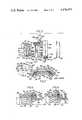
- FIG. 2is an exploded view, partially in section, of the coupling nut according to the present invention removed from one electrical connector of the assembly.
- FIG. 3is an exploded view of a lock pin taken along lines III--III of FIG. 2.
- FIG. 4is an end view taken along line IV--IV of FIG. 1.
- FIG. 5is a partial side view in section showing full-mate between the electrical connector assembly.
- FIG. 6is a partial side view in section showing the connector assembly at full mate in a locked condition.
- FIG. 7is an end view taken along lines VII--VII of FIG. 6.
- an electrical connector assemblyincludes coaxial first and second shells 100, 200 positioned for mating engagement and a coupling nut 300 mounted for rotation to first shell 100 for connecting the first shell and second shell in mating relationship.
- the first shell 100also considered a plug-type connector, includes a cylindrical front portion 120 having a front face 122, a rear portion 170 and an annular shoulder 140 medially of the shell portions, the rear portion 170 including a stepped groove 110 and an annular wall 130 circumjacent the annular shoulder.
- the annular shoulder 140includes a front face 142, a rear face 144 and a plurality of rachet teeth 150 on its outer circumferential surface.
- the first shellalso includes one or more female-type (i.e. socket) electrical contacts 128 retained therewithin by one or more dielectric inserts 126.
- the outer surface of front portion 120includes one or more axial keys 124 for orienting first shell 100 relative to second shell 200.
- An annular recess 132 forwardly of annular shoulder 140is adapted to receive a shield spring 134 for grounding the connector shells 100, 200 from radio frequency interference.
- the second shell 200also considered a receptacle-type connector, includes a front portion 220 having a front face 222, and inner wall 223 and external thread 210 on the outside surface thereof. Further, shell 200 includes one or more axially extending recess or keyways 224 for receiving the respective keys 124 on first shell 100, one or more dielectric inserts 226 mounted therewithin and one or more male-type (i.e. pin) electrical contacts 228 adapted to mate with the socket-type contacts 128 of first shell 100, the pin contacts 228 being retained within the dielectric inserts 226.
- the pin-socket contacts 128, 228could be other than shown.
- the coupling nut 300is rotatably mounted on first shell 100 and includes internal threads 310 adapted to mate with the external threads 210 on second shell 200 to draw the first and second shells 100, 200 together with contacts 128, 228 mated.
- an inwardly extending radial flange 336 on coupling nut 300is adapted to be received about annular wall 130 and captivated for rotation against rear face 144 of annular shoulder 140, radial flange 336 being retained against annular shoulder 140 and the coupling nut being retained on the shell by a retaining ring 160 received within stepped groove 110.
- coupling nut 300is a compound coupling member which comprises generally cylindrical first and second coaxial coupling sleeves 320, 330 mounted for rotation relative to one another with the second and inner sleeve 330 including radial flange 336 and carrying a plurality of radially movable, lock pins 350 biased by a spring member 370 from engagement with ratchet teeth 150 but adapted to be driven into engagement therewith for locking.
- Inner coupling sleeve 330is one-piece and comprises a tubular shell 332 including a rearward end portion having an exterior or first outer surface 339 and a medial shoulder 333 extending radially outward therefrom and defining an exterior or second outer surface 331 and a transverse end face 334 circumjacent outer surface 339, the radial flange 336 extending radially inward from the rearward end portion, the thread 310 being on the inner wall of tubular shell 332 and outer surfaces 339, 331 being concentric with one another relative to the primary axis of the coupling nut.
- a plurality of openings 338are disposed equiangularly about tubular shell 332, each opening extending radially through outer surface 339 and sized to receive one of the lock pins 350.
- Outer coupling sleeve 320is one piece and comprises a tubular shell 322 having an interior wall 321 and including a radial flange 326 extending radially inward from a rearward end portion thereof, radial flange 326 defining, respectively, inner and outer end walls 325, 327.
- An annular undercut 328 and an annular cam 329extend around the interior wall 321 circumjacent inner end wall 325 of radial flange 326, the undercut and cam being contiguous to define an annular cavity for receiving lock pin 350 and annular undercut 328 defining a transverse end wall 324 allowing rearward axial movement of outer coupling sleeve 320 relative to inner coupling sleeve 330.
- Retaining ring 160is disposed against radial flanges 326, 336.
- a frusto-conical annular spring 162is received in stepped groove 110 and has its rim biasing against retaining ring 160.
- Each lock pin 350is shown disposed in their respective openings 338 through inner coupling sleeve 330.
- Each lock pin 350although shown best in FIG. 3, includes a generally cylindrical body 351 having a domed end 354 for engaging undercut 328 and cam 329 and a pointed end 352 for engaging the ratchet teeth 150.
- spring member 370Cooperatively attached to each lock pin 350, shown best in FIG. 3, is spring member 370, the spring member being adapted to constantly and consistently bias its respective lock pin radially outwardly of its opening 338.
- Transverse end face 334is adapted to position the spring thereagainst.
- domed end 354is biased outwardly and into abutment with annular undercut 328 and pointed end 352 outwardly from engagement with the ratchet teeth. This represents an unlocked position of coupling nut 300 relative to shells 100, 200.
- a bayonet-type lock arrangement for simultaneously locking each of the lock pins 350 into their engaged relation with respective of the ratchet teeth 150comprises a bayonet slot 340 disposed in medial shoulder 333 of inner coupling sleeve 330 being adapted to receive a bayonet pin 348 extending radially inwardly from outer coupling sleeve 320.
- FIG. 2shows disassembly of coupling nut 300 from plug shell 100.
- Inner coupling sleeve 330includes flange 336 having inner and outer end walls 335, 337, respectively, with inner end wall 335 thereof being adapted to be abutted against rear face 144 of annular shoulder 140 to position the inner coupling sleeve relative to the plug shell.
- Bayonet slot 340is disposed within outer surface 331 of medial shoulder 333 of coupling sleeve 330, the slot extending from transverse end face 334 and including a humped entryway 342 at one end and an arcuate detent 346 at the other end, entryway 242 having transverse forward and rearward shoulders 344, 345 which define abutment faces for captivating the bayonet pin.
- bayonet pin 348is seated, respectively, against forward and rearward shoulders 344, 345 and rotation of outer coupling sleeve 320 constrains inner coupling sleeve 330 to rotate therewith.
- bayonet pin 348Upon coupled engagement, bayonet pin 348 is advanced in slot 340 to detent 346, whereby pins 350 are driven inwardly into ratchet teeth 150 and further rotation prevented.
- Annular spring 162allows rearward movement of bayonet pin 348 and forward bias to capture the bayonet pin 348 in detent 346.
- coupling nut thread 310is right-handed
- bayonet slot 340is right-handed and vice-versa.
- three bayonet slots 340 and corresponding bayonet pins 348would be provided equiangularly about their respective sleeves.
- Locking pin 350 and spring 370are shown aligned for mounting within opening 338 on inner coupling 330.
- FIG. 3is a detail view of a locking pin 350 disassembled from spring 370.
- Lock pin 350includes a generally cylindrical body 351 having domed end 354 and pointed end 352, body 351 further including including a transverse annular slot 356 extending therein medially of its ends.
- Spring member 370includes a flat plate 372 having a pair of skirts 374 extending therefrom, flat plate 372 having extend from one edge 373 thereof a U-shaped slot 376 sized to fit within annular slot 356 of the pin and the other edge 371 of the skirts and plate being adapted to abut the transverse end face 334 to secure spring member 370 and lock pin 350 together.
- FIG. 4is an end view through the plug shell 100 showing detail of coupling nut 300 in the unlocked position.
- Six lock pins 350are equiangularly disposed around the plug shell, each pin having its domed end 354 biased by skirts 374 into abutment against annular undercut 328 and pointed end 352 out of engagement with the ratchet teeth 150 disposed on annular shoulder 140, the ratchet teeth forming, respectively, a contiguous succession of peaks and valleys 154, 152, with valleys 152 being sized to receive pointed ends 352 of lock pin 350 for providing the locked position.
- FIG. 5shows a full mate condition wherein end face 222 of receptacle shell 200 has been drawn within coupling nut 300 and into abutment (i.e. metal-to-metal contact) with forward face 142 of annular shoulder 140 around plug shell 100.
- Each of the lock pins 350are in their unlocked position and biased radially outwardly in openings 338 from engagement with ratchet teeth 150.
- FIG. 6shows the full-mate condition wherein lock pins 350 are in locked engagement in respective valleys 152 of ratchet teeth 150.
- Outer coupling sleeve 320has been rotated in the coupling direction and advanced longitudinally forward relative to inner coupling sleeve 330, resulting in bayonet pin 348 being advanced through its slot 340 and into detent 346.
- annular undercut 328 and cam 329advance forwardly with the cam 329 driving the lock pins 350 downwardly (i.e. radially inward) and into engagement with ratchet teeth 150.
- FIG. 7shows an end view of the locked full-mate condition. Skirts 374 have been flattened against outer surface 339 of inner coupling sleeve 330 and pointed ends 352 of lock pins 350 driven into their respective valleys 152 of ratchet teeth 150.
- Coupling nut 300would be assembled by sliding inner coupling sleeve 330 over rear portion 170 of plug shell 100 and abutting its radial flange 337 against rear face 144 of annular shoulder 140; assembling spring member 370 with lock pins 350 by inserting the U-shaped slot 376 of spring member 370 into the annular slot 356 of lock pin 350; radially inserting cylindrical bodies 351 of each lock pin 350 into openings 338 of inner coupling sleeve 330; sliding outer coupling sleeve 320 over inner coupling sleeve 330, the domed ends 354 positioning themselves within the annular cavity and against annular undercut 328; advancing bayonet pin 348 into entryway 342 against abutment shoulders 344, 345; sliding retaining ring 160 over rear portion 170 of the plug shell and into abutment with radial flanges 326, 336; and captivating the assembly with annular spring 162 being received in stepped groove 110.
- the shells 100, 200would be positioned so that keys and keyways 124, 224 are aligned and then axially advanced towards each other until the thread 210 on the receptacle shell 200 is engaged by the thread 310 on the inner coupling sleeve 330.
- Rotation of coupling nut 300shown best in FIGS. 5 and 6, axially advances front portion 120 of the first shell inwardly into front portion 220 of the second shell, inner wall 223 of the second shell 200 compressing shield 134 into annular recess 136 with continued advance of the shell front portions 120, 220 advancing front face 222 into abutment against front face 142 of annular shoulder 140 when the full mate condition is achieved.
- Bayonet pin 348functions first to drive the coupling sleeves 320, 330 together as a unit during coupling/uncoupling direction rotation and second to actuate locking relation between the sleeves and first connector shell 100. Forward axial motion results from bayonet pin 348 being driven against forward shoulder 344 within humped entryway 342. As a result of this rotation, the shells 100, 200 do not corotate relative to one another but are axially drawn towards one another until end face 222 of the receptacle shell 200 is in metal-to-metal contact with the plug shell 100.
- Bayonet pin 348is advanced through through slot 340 and into register with arcuate detent 346 where upon annular spring 162 drives the outer coupling sleeve 320 forwardly relative to inner coupling sleeve 330 whereby the bayonet pin 348 is captured in the detent.
- Contact between forward faces of dielectric inserts 126, 226provides a slight rearward bias against the shells 100, 200, providing resistance which the bayonet pin must overcome to move forwardly and from its detent.
- bayonet slot 340could require left-handed advance of bayonet pin 348 relative to right-handed coupling advance of the inner coupling sleeve 330.
Landscapes
- Details Of Connecting Devices For Male And Female Coupling (AREA)
Abstract
Description
Claims (9)
Priority Applications (1)
| Application Number | Priority Date | Filing Date | Title |
|---|---|---|---|
| US06/431,969US4478473A (en) | 1982-09-30 | 1982-09-30 | Coupling nut for an electrical connector |
Applications Claiming Priority (1)
| Application Number | Priority Date | Filing Date | Title |
|---|---|---|---|
| US06/431,969US4478473A (en) | 1982-09-30 | 1982-09-30 | Coupling nut for an electrical connector |
Publications (1)
| Publication Number | Publication Date |
|---|---|
| US4478473Atrue US4478473A (en) | 1984-10-23 |
Family
ID=23714208
Family Applications (1)
| Application Number | Title | Priority Date | Filing Date |
|---|---|---|---|
| US06/431,969Expired - Fee RelatedUS4478473A (en) | 1982-09-30 | 1982-09-30 | Coupling nut for an electrical connector |
Country Status (1)
| Country | Link |
|---|---|
| US (1) | US4478473A (en) |
Cited By (68)
| Publication number | Priority date | Publication date | Assignee | Title |
|---|---|---|---|---|
| US4547032A (en)* | 1984-08-03 | 1985-10-15 | Automation Industries, Inc. | Locking means for a plug and receptacle electrical connector |
| US4702537A (en)* | 1985-05-03 | 1987-10-27 | Matrix Science Corporation | Quick-disconnect electrical connector coupling assembly for use with bayonet pin coupling system |
| EP0512323A1 (en)* | 1991-05-02 | 1992-11-11 | The Whitaker Corporation | Connector assembly |
| US6183293B1 (en)* | 1998-08-28 | 2001-02-06 | Itt Manufacturing Enterprises, Inc. | Electrical connector latching mechanism |
| US6450353B1 (en) | 1999-09-27 | 2002-09-17 | The Lamson & Sessions Co. | Floor box cover assembly |
| US6887102B1 (en) | 2004-04-13 | 2005-05-03 | Corning Gilbert Inc. | Coaxial cable connector and nut member |
| US20100273342A1 (en)* | 2009-04-22 | 2010-10-28 | Christopher Michael Hankins | Bayonet connector |
| US20140227900A1 (en)* | 2014-04-17 | 2014-08-14 | Tyco Electronics Corporation | Connector having coupling mechanism |
| US9188747B2 (en) | 2011-05-23 | 2015-11-17 | Senko Advanced Components, Inc. | True one piece housing fiber optic adapter |
| US9297964B2 (en) | 2014-04-18 | 2016-03-29 | Senko Advanced Components, Inc. | Optical fiber connector assembly |
| US9397441B2 (en) | 2013-03-15 | 2016-07-19 | Cinch Connections, Inc. | Connector with anti-decoupling mechanism |
| US9494745B2 (en) | 2015-01-16 | 2016-11-15 | Senko Advanced Components, Inc. | Sealable communication cable connection assemblies |
| US9531120B2 (en) | 2014-09-04 | 2016-12-27 | Conesys, Inc. | Circular connectors |
| US9618703B2 (en) | 2013-10-03 | 2017-04-11 | Senko Advanced Components, Inc. | Connector housing for securing an optical cable and methods of use and manufacture thereof |
| US9618702B2 (en) | 2014-06-09 | 2017-04-11 | Senko Advanced Components, Inc. | Reduced-profile data transmission element connectors, adapters, and connection assemblies thereof |
| US9658409B2 (en) | 2015-03-03 | 2017-05-23 | Senko Advanced Components, Inc. | Optical fiber connector with changeable polarity |
| US20180131130A1 (en)* | 2016-11-10 | 2018-05-10 | A.A.G. Stucchi S.R.L. | Linear connection assembly for electrical conductors with high locking reliability |
| US20180223888A1 (en)* | 2017-02-03 | 2018-08-09 | Itt Manufacturing Enterprises, Llc | Anti-vibration locking connector |
| US10146016B1 (en) | 2017-05-10 | 2018-12-04 | Senko Advanced Components, Inc | MPO micro-latchlock connector |
| US10185100B2 (en) | 2017-01-30 | 2019-01-22 | Senko Advanced Components, Inc | Modular connector and adapter assembly using a removable anchor device |
| US10191230B2 (en)* | 2017-01-30 | 2019-01-29 | Senko Advanced Components, Inc. | Optical connectors with reversible polarity |
| US10209461B2 (en) | 2017-04-07 | 2019-02-19 | Senko Advanced Components | Behind the wall optical connector with reduced components |
| US10228521B2 (en) | 2016-12-05 | 2019-03-12 | Senko Advanced Components, Inc. | Narrow width adapters and connectors with modular latching arm |
| US10281669B2 (en) | 2017-07-14 | 2019-05-07 | Senko Advance Components, Inc. | Ultra-small form factor optical connectors |
| US10295759B2 (en) | 2017-05-18 | 2019-05-21 | Senko Advanced Components, Inc. | Optical connector with forward-biasing projections |
| US10359583B2 (en) | 2017-04-07 | 2019-07-23 | Senko Advanced Components, Inc. | Behind the wall optical connector with reduced components |
| US10359576B2 (en) | 2017-06-15 | 2019-07-23 | Senko Advanced Components, Inc. | SC low profile connector with optional boot |
| US10401576B2 (en) | 2017-05-10 | 2019-09-03 | Senko Advanced Components, Inc. | MPO micro-latch-lock connector |
| US10416394B2 (en) | 2017-01-30 | 2019-09-17 | Senko Advanced Components, Inc. | Fiber optic receptacle with integrated device therein |
| US10444441B1 (en) | 2018-08-10 | 2019-10-15 | Senko Advanced Components, Inc. | Pivotable housing for a fiber optic connector |
| US10444442B2 (en) | 2017-11-03 | 2019-10-15 | Senko Advanced Components, Inc. | MPO optical fiber connector |
| US10444444B2 (en) | 2017-01-30 | 2019-10-15 | Senko Advanced Components, Inc. | Remote release tab connector assembly |
| US10641972B2 (en) | 2017-08-17 | 2020-05-05 | Senko Advanced Components, Inc | Anti-jam alignment sleeve holder or connector housing for a ferrule assembly |
| US10705300B2 (en) | 2017-07-14 | 2020-07-07 | Senko Advanced Components, Inc. | Small form factor fiber optic connector with multi-purpose boot assembly |
| US10718910B2 (en) | 2017-05-03 | 2020-07-21 | Senko Advanced Components, Inc | Field terminated ruggedized fiber optic connector system |
| US10718911B2 (en) | 2017-08-24 | 2020-07-21 | Senko Advanced Components, Inc. | Ultra-small form factor optical connectors using a push-pull boot receptacle release |
| US10725248B2 (en) | 2017-01-30 | 2020-07-28 | Senko Advanced Components, Inc. | Fiber optic receptacle with integrated device therein incorporating a behind-the-wall fiber optic receptacle |
| US10754098B2 (en) | 2017-04-07 | 2020-08-25 | Senko Advanced Components, Inc. | Behind the wall optical connector with reduced components |
| US10866371B2 (en) | 2016-06-28 | 2020-12-15 | Senko Advanced Components, Inc. | Adapter system for multi-fiber mechanical transfer type ferrule |
| US10921531B2 (en) | 2018-09-12 | 2021-02-16 | Senko Advanced Components, Inc. | LC type connector with push/pull assembly for releasing connector from a receptacle using a cable boot |
| US10921530B2 (en) | 2018-09-12 | 2021-02-16 | Senko Advanced Components, Inc. | LC type connector with push/pull assembly for releasing connector from a receptacle using a cable boot |
| US10921528B2 (en) | 2018-06-07 | 2021-02-16 | Senko Advanced Components, Inc. | Dual spring multi-fiber optic connector |
| US10983290B2 (en) | 2016-12-05 | 2021-04-20 | Senko Advanced Components, Inc. | Fiber optic connector with releaseable pull/push tab with securing protrusions |
| US10989884B2 (en) | 2017-04-07 | 2021-04-27 | Senko Advanced Components, Inc. | Behind the wall optical connector with reduced components |
| US11002923B2 (en) | 2017-11-21 | 2021-05-11 | Senko Advanced Components, Inc. | Fiber optic connector with cable boot release having a two-piece clip assembly |
| US11041993B2 (en) | 2018-04-19 | 2021-06-22 | Senko Advanced Components, Inc. | Fiber optic adapter with removable insert for polarity change and removal tool for the same |
| US11073664B2 (en) | 2018-08-13 | 2021-07-27 | Senko Advanced Components, Inc. | Cable boot assembly for releasing fiber optic connector from a receptacle |
| US11073662B2 (en) | 2015-05-29 | 2021-07-27 | Senko Advanced Components, Inc. | Optical fiber connector with changeable gender |
| US11081838B2 (en)* | 2017-08-08 | 2021-08-03 | Phoenix Contact Gmbh & Co. Kg | Electrical connector part having a locking element |
| US11086087B2 (en) | 2018-09-12 | 2021-08-10 | Senko Advanced Components, Inc. | LC type connector with clip-on push/pull tab for releasing connector from a receptacle using a cable boot |
| US11112566B2 (en) | 2018-03-19 | 2021-09-07 | Senko Advanced Components, Inc. | Removal tool for removing a plural of micro optical connectors from an adapter interface |
| US11175464B2 (en) | 2018-11-25 | 2021-11-16 | Senko Advanced Components, Inc. | Open ended spring body for use in an optical fiber connector |
| US11187857B2 (en) | 2018-07-15 | 2021-11-30 | Senko Advanced Components, Inc. | Ultra-small form factor optical connector and adapter |
| US11314024B2 (en) | 2019-06-13 | 2022-04-26 | Senko Advanced Components, Inc. | Lever actuated latch arm for releasing a fiber optic connector from a receptacle port and method of use |
| US11320606B2 (en) | 2017-01-30 | 2022-05-03 | Senko Advanced Components, Inc. | Optical connector |
| US11340406B2 (en) | 2019-04-19 | 2022-05-24 | Senko Advanced Components, Inc. | Small form factor fiber optic connector with resilient latching mechanism for securing within a hook-less receptacle |
| US11353664B1 (en) | 2019-08-21 | 2022-06-07 | Senko Advanced Components, Inc. | Fiber optic connector |
| US20220224050A1 (en)* | 2020-10-16 | 2022-07-14 | Ultratech | Assembly Comprising a First Connector, a Second Connector and a Coding System Selectively Allowing Connection |
| US20220320794A1 (en)* | 2019-05-28 | 2022-10-06 | Amphenol-Tuchel Industrial GmbH | Plug connector with locking system |
| US11467354B2 (en) | 2019-07-23 | 2022-10-11 | Senko Advanced Components, Inc. | Ultra-small form factor receptacle for receiving a fiber optic connector opposing a ferrule assembly |
| US11520111B2 (en) | 2019-11-13 | 2022-12-06 | Senko Advanced Components, Inc. | Fiber optic connector |
| US11579379B2 (en) | 2019-03-28 | 2023-02-14 | Senko Advanced Components, Inc. | Fiber optic adapter assembly |
| US11806831B2 (en) | 2018-11-21 | 2023-11-07 | Senko Advanced Components, Inc. | Fixture and method for polishing fiber optic connector ferrules |
| US11822133B2 (en) | 2017-07-14 | 2023-11-21 | Senko Advanced Components, Inc. | Ultra-small form factor optical connector and adapter |
| US20240168243A1 (en)* | 2017-12-19 | 2024-05-23 | Us Conec Ltd. | Mini duplex connector with push-pull polarity mechanism and carrier |
| US12001064B2 (en) | 2017-07-14 | 2024-06-04 | Senko Advanced Components, Inc. | Small form factor fiber optic connector with multi-purpose boot |
| US12038613B2 (en) | 2019-03-28 | 2024-07-16 | Senko Advanced Components, Inc. | Behind-the-wall optical connector and assembly of the same |
| WO2024261081A1 (en)* | 2023-06-21 | 2024-12-26 | Karl Storz Se & Co. Kg | Interface for an operation image-capture system |
Citations (4)
| Publication number | Priority date | Publication date | Assignee | Title |
|---|---|---|---|---|
| US3170337A (en)* | 1964-03-19 | 1965-02-23 | Montgomery & Company Inc | Screw and nut assembly |
| US3343852A (en)* | 1964-06-08 | 1967-09-26 | Cannon Electric Great Britain | Locking nuts and electrical connectors incorporating locking nuts |
| US3470524A (en)* | 1967-06-19 | 1969-09-30 | Deutsch Co Elec Comp | Push-pull connector |
| US3601764A (en)* | 1969-01-28 | 1971-08-24 | Bunker Ramo | Lock device for coupling means |
- 1982
- 1982-09-30USUS06/431,969patent/US4478473A/ennot_activeExpired - Fee Related
Patent Citations (4)
| Publication number | Priority date | Publication date | Assignee | Title |
|---|---|---|---|---|
| US3170337A (en)* | 1964-03-19 | 1965-02-23 | Montgomery & Company Inc | Screw and nut assembly |
| US3343852A (en)* | 1964-06-08 | 1967-09-26 | Cannon Electric Great Britain | Locking nuts and electrical connectors incorporating locking nuts |
| US3470524A (en)* | 1967-06-19 | 1969-09-30 | Deutsch Co Elec Comp | Push-pull connector |
| US3601764A (en)* | 1969-01-28 | 1971-08-24 | Bunker Ramo | Lock device for coupling means |
Cited By (131)
| Publication number | Priority date | Publication date | Assignee | Title |
|---|---|---|---|---|
| US4547032A (en)* | 1984-08-03 | 1985-10-15 | Automation Industries, Inc. | Locking means for a plug and receptacle electrical connector |
| US4702537A (en)* | 1985-05-03 | 1987-10-27 | Matrix Science Corporation | Quick-disconnect electrical connector coupling assembly for use with bayonet pin coupling system |
| FR2619257A1 (en)* | 1985-05-03 | 1989-02-10 | Matrix Science Corp | ELECTRICAL CONNECTOR ASSEMBLY WITH QUICK DISCONNECT |
| EP0512323A1 (en)* | 1991-05-02 | 1992-11-11 | The Whitaker Corporation | Connector assembly |
| US6183293B1 (en)* | 1998-08-28 | 2001-02-06 | Itt Manufacturing Enterprises, Inc. | Electrical connector latching mechanism |
| US6450353B1 (en) | 1999-09-27 | 2002-09-17 | The Lamson & Sessions Co. | Floor box cover assembly |
| US6887102B1 (en) | 2004-04-13 | 2005-05-03 | Corning Gilbert Inc. | Coaxial cable connector and nut member |
| US20100273342A1 (en)* | 2009-04-22 | 2010-10-28 | Christopher Michael Hankins | Bayonet connector |
| US7988479B2 (en)* | 2009-04-22 | 2011-08-02 | Christopher Michael Hankins | Bayonet connector |
| US9188747B2 (en) | 2011-05-23 | 2015-11-17 | Senko Advanced Components, Inc. | True one piece housing fiber optic adapter |
| US9397441B2 (en) | 2013-03-15 | 2016-07-19 | Cinch Connections, Inc. | Connector with anti-decoupling mechanism |
| US9618703B2 (en) | 2013-10-03 | 2017-04-11 | Senko Advanced Components, Inc. | Connector housing for securing an optical cable and methods of use and manufacture thereof |
| US9437965B2 (en)* | 2014-04-17 | 2016-09-06 | Tyco Electronics Corporation | Connector having coupling mechanism |
| US20140227900A1 (en)* | 2014-04-17 | 2014-08-14 | Tyco Electronics Corporation | Connector having coupling mechanism |
| US9297964B2 (en) | 2014-04-18 | 2016-03-29 | Senko Advanced Components, Inc. | Optical fiber connector assembly |
| US10197740B2 (en) | 2014-06-09 | 2019-02-05 | Senko Advanced Components, Inc. | Reduced-profile data transmission element connectors, adapters, and connection assemblies thereof |
| US9618702B2 (en) | 2014-06-09 | 2017-04-11 | Senko Advanced Components, Inc. | Reduced-profile data transmission element connectors, adapters, and connection assemblies thereof |
| US11002918B2 (en) | 2014-06-09 | 2021-05-11 | Senko Advanced Components, Inc. | Reduced-profile data transmission element connectors, adapters, and connection assemblies thereof |
| US11402587B2 (en) | 2014-06-09 | 2022-08-02 | Senko Advanced Components, Inc. | Reduced-profile data transmission element connectors, adapters, and connection assemblies thereof |
| US9531120B2 (en) | 2014-09-04 | 2016-12-27 | Conesys, Inc. | Circular connectors |
| US9494745B2 (en) | 2015-01-16 | 2016-11-15 | Senko Advanced Components, Inc. | Sealable communication cable connection assemblies |
| US9658409B2 (en) | 2015-03-03 | 2017-05-23 | Senko Advanced Components, Inc. | Optical fiber connector with changeable polarity |
| US11422319B2 (en) | 2015-03-03 | 2022-08-23 | Senko Advanced Components, Inc. | Optical fiber connector with changeable polarity |
| US11079557B2 (en) | 2015-03-03 | 2021-08-03 | Senko Advanced Components, Inc. | Optical fiber connector with changeable polarity |
| US12259585B2 (en) | 2015-03-03 | 2025-03-25 | Senko Advanced Components, Inc. | Optical fiber connector with changeable polarity |
| US11609388B2 (en) | 2015-03-03 | 2023-03-21 | Senko Advanced Components, Inc. | Optical fiber connector with changeable polarity |
| US10539750B2 (en) | 2015-03-03 | 2020-01-21 | Senko Advanced Components, Inc | Optical fiber connector with changeable polarity |
| US11391895B2 (en) | 2015-03-03 | 2022-07-19 | Senko Advanced Components, Inc. | Optical fiber connector with changeable polarity |
| US12386125B2 (en) | 2015-05-29 | 2025-08-12 | Senko Advanced Components, Inc. | Optical fiber connector with changeable gender |
| US11585988B2 (en) | 2015-05-29 | 2023-02-21 | Senko Advanced Components, Inc. | Optical fiber connector with changeable gender |
| US11073662B2 (en) | 2015-05-29 | 2021-07-27 | Senko Advanced Components, Inc. | Optical fiber connector with changeable gender |
| US11275219B2 (en) | 2015-05-29 | 2022-03-15 | Senko Advanced Components, Inc. | Optical fiber connector with changeable gender |
| US11892688B2 (en) | 2015-05-29 | 2024-02-06 | Senko Advanced Components, Inc. | Optical fiber connector with changeable gender |
| US10866371B2 (en) | 2016-06-28 | 2020-12-15 | Senko Advanced Components, Inc. | Adapter system for multi-fiber mechanical transfer type ferrule |
| US10348033B2 (en)* | 2016-11-10 | 2019-07-09 | A.A.G Stucchi S.R.L. | Linear connection assembly for electrical conductors with high locking reliability |
| US20180131130A1 (en)* | 2016-11-10 | 2018-05-10 | A.A.G. Stucchi S.R.L. | Linear connection assembly for electrical conductors with high locking reliability |
| US12158623B2 (en) | 2016-12-05 | 2024-12-03 | Senko Advanced Components, Inc. | Optical fiber connector |
| US11287583B2 (en) | 2016-12-05 | 2022-03-29 | Senko Advanced Components, Inc. | Narrow width fiber optic connector |
| US10520689B2 (en) | 2016-12-05 | 2019-12-31 | Senko Advanced Components, Inc. | Receiver device for accepting narrow width connectors |
| US10983290B2 (en) | 2016-12-05 | 2021-04-20 | Senko Advanced Components, Inc. | Fiber optic connector with releaseable pull/push tab with securing protrusions |
| US11448835B2 (en) | 2016-12-05 | 2022-09-20 | Senko Advanced Components, Inc. | Fiber optic connector with releasable pull/push tab with securing protrusions |
| US10228521B2 (en) | 2016-12-05 | 2019-03-12 | Senko Advanced Components, Inc. | Narrow width adapters and connectors with modular latching arm |
| US10539748B2 (en) | 2016-12-05 | 2020-01-21 | Senko Advanced Components, Inc | Network system of narrow width connectors and receiver devices |
| US10739533B2 (en) | 2016-12-05 | 2020-08-11 | Senko Advanced Components, Inc. | Receiver configured to accept a removable anchor device for securing a fiber optic connector within the receiver |
| US10976505B2 (en) | 2017-01-30 | 2021-04-13 | Senko Advanced Components, Inc. | Optical connectors with reversible polarity and method of use |
| US10877226B2 (en) | 2017-01-30 | 2020-12-29 | Senko Advanced Components, Inc. | Remote release tab connector assembly |
| US10641968B2 (en) | 2017-01-30 | 2020-05-05 | Senko Advanced Components, Inc. | Adapter for narrow width connectors |
| US11314021B2 (en) | 2017-01-30 | 2022-04-26 | Senko Advanced Components, Inc. | Fiber optic system for narrow width fiber optic connectors, adapters and transceivers |
| US11320606B2 (en) | 2017-01-30 | 2022-05-03 | Senko Advanced Components, Inc. | Optical connector |
| US10444444B2 (en) | 2017-01-30 | 2019-10-15 | Senko Advanced Components, Inc. | Remote release tab connector assembly |
| US10185100B2 (en) | 2017-01-30 | 2019-01-22 | Senko Advanced Components, Inc | Modular connector and adapter assembly using a removable anchor device |
| US10983286B2 (en) | 2017-01-30 | 2021-04-20 | Senko Advanced Components, Inc. | Fiber optic system for narrow width fiber optic connectors, adapters and transceivers |
| US10191230B2 (en)* | 2017-01-30 | 2019-01-29 | Senko Advanced Components, Inc. | Optical connectors with reversible polarity |
| US10725248B2 (en) | 2017-01-30 | 2020-07-28 | Senko Advanced Components, Inc. | Fiber optic receptacle with integrated device therein incorporating a behind-the-wall fiber optic receptacle |
| US10585247B2 (en) | 2017-01-30 | 2020-03-10 | Senko Advanced Components, Inc | Modular connector and adapter devices |
| US10527802B2 (en)* | 2017-01-30 | 2020-01-07 | Senko Advanced Components, Inc | Optical connectors with reversible polarity |
| US11774685B2 (en) | 2017-01-30 | 2023-10-03 | Senko Advanced Components, Inc | Adapter for optical connectors |
| US11675137B2 (en) | 2017-01-30 | 2023-06-13 | Senko Advanced Components, Inc. | Fiber optic system for narrow width fiber optic connectors, adapters and transceivers |
| US11435533B2 (en) | 2017-01-30 | 2022-09-06 | Senko Advanced Components, Inc. | Fiber optic receptacle with integrated device therein incorporating a behind-the-wall fiber optic receptacle |
| US10416394B2 (en) | 2017-01-30 | 2019-09-17 | Senko Advanced Components, Inc. | Fiber optic receptacle with integrated device therein |
| US10598204B2 (en)* | 2017-02-03 | 2020-03-24 | Itt Manufacturing Enterprises, Llc | Anti-vibration locking connector |
| US20180223888A1 (en)* | 2017-02-03 | 2018-08-09 | Itt Manufacturing Enterprises, Llc | Anti-vibration locking connector |
| US11378119B2 (en)* | 2017-02-03 | 2022-07-05 | Itt Manufacturing Enterprises, Llc | Anti-vibration locking connector |
| US10989884B2 (en) | 2017-04-07 | 2021-04-27 | Senko Advanced Components, Inc. | Behind the wall optical connector with reduced components |
| US10754098B2 (en) | 2017-04-07 | 2020-08-25 | Senko Advanced Components, Inc. | Behind the wall optical connector with reduced components |
| US11435535B2 (en) | 2017-04-07 | 2022-09-06 | Senko Advanced Components, Inc. | Behind the wall optical connector with reduced components |
| US10359583B2 (en) | 2017-04-07 | 2019-07-23 | Senko Advanced Components, Inc. | Behind the wall optical connector with reduced components |
| US10209461B2 (en) | 2017-04-07 | 2019-02-19 | Senko Advanced Components | Behind the wall optical connector with reduced components |
| US10718910B2 (en) | 2017-05-03 | 2020-07-21 | Senko Advanced Components, Inc | Field terminated ruggedized fiber optic connector system |
| US10146016B1 (en) | 2017-05-10 | 2018-12-04 | Senko Advanced Components, Inc | MPO micro-latchlock connector |
| US10684425B2 (en) | 2017-05-10 | 2020-06-16 | Senko Advanced Components, Inc | MPO microlatch lock connector |
| US11320605B2 (en) | 2017-05-10 | 2022-05-03 | Senko Advanced Components, Inc. | MPO microlatch lock connector |
| US10401576B2 (en) | 2017-05-10 | 2019-09-03 | Senko Advanced Components, Inc. | MPO micro-latch-lock connector |
| US10520686B2 (en) | 2017-05-18 | 2019-12-31 | Senko Advanced Components, Inc. | Optical connector with one-piece body |
| US11256041B2 (en) | 2017-05-18 | 2022-02-22 | Senko Advanced Components, Inc. | Optical connector with one-piece body |
| US10295759B2 (en) | 2017-05-18 | 2019-05-21 | Senko Advanced Components, Inc. | Optical connector with forward-biasing projections |
| US10712511B2 (en) | 2017-05-18 | 2020-07-14 | Senko Advanced Components, Inc. | Optical connector with one-piece body |
| US10545297B2 (en) | 2017-06-15 | 2020-01-28 | Senko Advanced Components, Inc. | SC low profile connector |
| US10359576B2 (en) | 2017-06-15 | 2019-07-23 | Senko Advanced Components, Inc. | SC low profile connector with optional boot |
| US12001064B2 (en) | 2017-07-14 | 2024-06-04 | Senko Advanced Components, Inc. | Small form factor fiber optic connector with multi-purpose boot |
| US11809006B2 (en) | 2017-07-14 | 2023-11-07 | Senko Advanced Components, Inc. | Ultra-small form factor optical connectors used as part of a reconfigurable outer housing |
| US10705300B2 (en) | 2017-07-14 | 2020-07-07 | Senko Advanced Components, Inc. | Small form factor fiber optic connector with multi-purpose boot assembly |
| US12228774B2 (en) | 2017-07-14 | 2025-02-18 | Senko Advanced Components, Inc. | Ultra-small form factor optical connector and adapter |
| US11280972B2 (en) | 2017-07-14 | 2022-03-22 | Senko Advanced Components, Inc. | Ultra-small form factor optical connectors used as part of a reconfigurable outer housing |
| US10281669B2 (en) | 2017-07-14 | 2019-05-07 | Senko Advance Components, Inc. | Ultra-small form factor optical connectors |
| US11307369B2 (en) | 2017-07-14 | 2022-04-19 | Senko Advanced Components, Inc. | Ultra-small form factor optical connectors used as part of a reconfigurable outer housing |
| US11169338B2 (en) | 2017-07-14 | 2021-11-09 | Senko Advanced Components, Inc. | Ultra-small form factor optical connectors |
| US11487067B2 (en) | 2017-07-14 | 2022-11-01 | Senko Advanced Components, Inc. | Ultra-small form factor optical connectors |
| US11061190B2 (en) | 2017-07-14 | 2021-07-13 | Senko Advanced Components, Inc. | Small form factor fiber optic connector with multi-purpose boot assembly |
| US11474315B2 (en) | 2017-07-14 | 2022-10-18 | Senko Advanced Components, Inc. | Ultra-small form factor optical connectors used as part of a reconfigurable outer housing |
| US11585989B2 (en) | 2017-07-14 | 2023-02-21 | Senko Advanced Components, Inc. | Small form factor fiber optic connector with multi-purpose boot |
| US11340413B2 (en) | 2017-07-14 | 2022-05-24 | Senko Advanced Components, Inc. | Ultra-small form factor optical connectors used as part of a reconfigurable outer housing |
| US10859778B2 (en) | 2017-07-14 | 2020-12-08 | Senko Advanced Components, Inc. | Ultra-small form factor optical connectors used as part of a reconfigurable outer housing |
| US10281668B2 (en) | 2017-07-14 | 2019-05-07 | Senko Advanced Components, Inc. | Ultra-small form factor optical connectors |
| US12248191B2 (en) | 2017-07-14 | 2025-03-11 | Senko Advanced Components, Inc. | Fiber optical connectors |
| US11822133B2 (en) | 2017-07-14 | 2023-11-21 | Senko Advanced Components, Inc. | Ultra-small form factor optical connector and adapter |
| US11081838B2 (en)* | 2017-08-08 | 2021-08-03 | Phoenix Contact Gmbh & Co. Kg | Electrical connector part having a locking element |
| US11092760B2 (en) | 2017-08-17 | 2021-08-17 | Senko Advanced Components, Inc. | Anti-jam alignment sleeve holder or connector housing for a ferrule assembly |
| US10641972B2 (en) | 2017-08-17 | 2020-05-05 | Senko Advanced Components, Inc | Anti-jam alignment sleeve holder or connector housing for a ferrule assembly |
| US10718911B2 (en) | 2017-08-24 | 2020-07-21 | Senko Advanced Components, Inc. | Ultra-small form factor optical connectors using a push-pull boot receptacle release |
| US10795095B2 (en) | 2017-11-03 | 2020-10-06 | Senko Advanced Components, Inc. | MPO optical fiber connector with a backpost having protrusions to align a crimp ring |
| US10444442B2 (en) | 2017-11-03 | 2019-10-15 | Senko Advanced Components, Inc. | MPO optical fiber connector |
| US11002923B2 (en) | 2017-11-21 | 2021-05-11 | Senko Advanced Components, Inc. | Fiber optic connector with cable boot release having a two-piece clip assembly |
| US11480741B2 (en) | 2017-11-21 | 2022-10-25 | Senko Advanced Components, Inc. | Fiber optic connector with cable boot release |
| US20240168243A1 (en)* | 2017-12-19 | 2024-05-23 | Us Conec Ltd. | Mini duplex connector with push-pull polarity mechanism and carrier |
| US12124093B2 (en)* | 2017-12-19 | 2024-10-22 | Us Conec Ltd. | Adapter for small form factor duplex fiber optic connectors |
| US11112566B2 (en) | 2018-03-19 | 2021-09-07 | Senko Advanced Components, Inc. | Removal tool for removing a plural of micro optical connectors from an adapter interface |
| US11041993B2 (en) | 2018-04-19 | 2021-06-22 | Senko Advanced Components, Inc. | Fiber optic adapter with removable insert for polarity change and removal tool for the same |
| US10921528B2 (en) | 2018-06-07 | 2021-02-16 | Senko Advanced Components, Inc. | Dual spring multi-fiber optic connector |
| US11187857B2 (en) | 2018-07-15 | 2021-11-30 | Senko Advanced Components, Inc. | Ultra-small form factor optical connector and adapter |
| US10444441B1 (en) | 2018-08-10 | 2019-10-15 | Senko Advanced Components, Inc. | Pivotable housing for a fiber optic connector |
| US11073664B2 (en) | 2018-08-13 | 2021-07-27 | Senko Advanced Components, Inc. | Cable boot assembly for releasing fiber optic connector from a receptacle |
| US10921530B2 (en) | 2018-09-12 | 2021-02-16 | Senko Advanced Components, Inc. | LC type connector with push/pull assembly for releasing connector from a receptacle using a cable boot |
| US11086087B2 (en) | 2018-09-12 | 2021-08-10 | Senko Advanced Components, Inc. | LC type connector with clip-on push/pull tab for releasing connector from a receptacle using a cable boot |
| US11500164B2 (en) | 2018-09-12 | 2022-11-15 | Senko Advanced Components, Inc. | LC type connector with push/pull assembly for releasing connector from a receptacle using a cable boot |
| US10921531B2 (en) | 2018-09-12 | 2021-02-16 | Senko Advanced Components, Inc. | LC type connector with push/pull assembly for releasing connector from a receptacle using a cable boot |
| US12311499B2 (en) | 2018-11-21 | 2025-05-27 | Senko Advanced Components, Inc. | Fixture and method for polishing fiber optic connector |
| US11806831B2 (en) | 2018-11-21 | 2023-11-07 | Senko Advanced Components, Inc. | Fixture and method for polishing fiber optic connector ferrules |
| US11175464B2 (en) | 2018-11-25 | 2021-11-16 | Senko Advanced Components, Inc. | Open ended spring body for use in an optical fiber connector |
| US12038613B2 (en) | 2019-03-28 | 2024-07-16 | Senko Advanced Components, Inc. | Behind-the-wall optical connector and assembly of the same |
| US11579379B2 (en) | 2019-03-28 | 2023-02-14 | Senko Advanced Components, Inc. | Fiber optic adapter assembly |
| US11340406B2 (en) | 2019-04-19 | 2022-05-24 | Senko Advanced Components, Inc. | Small form factor fiber optic connector with resilient latching mechanism for securing within a hook-less receptacle |
| US20220320794A1 (en)* | 2019-05-28 | 2022-10-06 | Amphenol-Tuchel Industrial GmbH | Plug connector with locking system |
| US12322899B2 (en)* | 2019-05-28 | 2025-06-03 | Amphenol-Tuchel Industrial GmbH | Plug connector with locking system |
| US11314024B2 (en) | 2019-06-13 | 2022-04-26 | Senko Advanced Components, Inc. | Lever actuated latch arm for releasing a fiber optic connector from a receptacle port and method of use |
| US11467354B2 (en) | 2019-07-23 | 2022-10-11 | Senko Advanced Components, Inc. | Ultra-small form factor receptacle for receiving a fiber optic connector opposing a ferrule assembly |
| US11353664B1 (en) | 2019-08-21 | 2022-06-07 | Senko Advanced Components, Inc. | Fiber optic connector |
| US11520111B2 (en) | 2019-11-13 | 2022-12-06 | Senko Advanced Components, Inc. | Fiber optic connector |
| US20220224050A1 (en)* | 2020-10-16 | 2022-07-14 | Ultratech | Assembly Comprising a First Connector, a Second Connector and a Coding System Selectively Allowing Connection |
| US11600949B2 (en)* | 2020-10-16 | 2023-03-07 | Ultratech | Assembly comprising a first connector, a second connector and a coding system selectively allowing connection |
| WO2024261081A1 (en)* | 2023-06-21 | 2024-12-26 | Karl Storz Se & Co. Kg | Interface for an operation image-capture system |
Similar Documents
| Publication | Publication Date | Title |
|---|---|---|
| US4478473A (en) | Coupling nut for an electrical connector | |
| US4464001A (en) | Coupling nut having an anti-decoupling device | |
| US4464000A (en) | Electrical connector assembly having an anti-decoupling device | |
| US5456611A (en) | Mini-UHF snap-on plug | |
| US4484790A (en) | Anti-decoupling device for an electrical connector | |
| US4497530A (en) | Electrical connector having a coupling indicator | |
| US4165910A (en) | Electrical connector | |
| EP0893852B1 (en) | Connector with releasable mounting flange | |
| CA1163339A (en) | Electrical connector coupling pin | |
| CA2352541A1 (en) | Electrical plug housing | |
| US4534607A (en) | Connector assembly and coupling ring | |
| EP1630905B1 (en) | Multiphase connector | |
| GB2373380A (en) | Push-pull quick-connect connectors | |
| US4359255A (en) | Coupling ring having detent means | |
| US4639064A (en) | Anti-decoupling resisting and EMI shielding means for an electrical connector assembly | |
| US4457469A (en) | Coupling nut for an electrical connector | |
| KR20000052302A (en) | Handle operated power connector | |
| US7377799B2 (en) | Electrical connector having improved fastening device | |
| CA1153437A (en) | Electrical connector coupling member | |
| CA1219647A (en) | Electrical connector assembly having an anti- decoupling device | |
| US4457572A (en) | Coupling nut for an electrical connector | |
| US4462652A (en) | Coupling nut for an electrical connector | |
| US4548458A (en) | Electrical connector having a molded anti-decoupling mechanism | |
| US4448470A (en) | Coupling member and an electrical connector | |
| US4530559A (en) | Locking means for a plug and receptacle connector |
Legal Events
| Date | Code | Title | Description |
|---|---|---|---|
| AS | Assignment | Owner name:BENDIX CORPORATION THE, BENDIX CENTER, SOUTHFIELD, Free format text:ASSIGNMENT OF ASSIGNORS INTEREST.;ASSIGNOR:FREAR, DAVID L.;REEL/FRAME:004082/0130 Effective date:19820922 | |
| AS | Assignment | Owner name:ALLIED CORPORATION COLUMBIA ROAD AND PARK AVE., MO Free format text:ASSIGNMENT OF ASSIGNORS INTEREST.;ASSIGNOR:BENDIX CORPORATION THE, A DE CORP;REEL/FRAME:004303/0534 Effective date:19840921 | |
| FEPP | Fee payment procedure | Free format text:PAYOR NUMBER ASSIGNED (ORIGINAL EVENT CODE: ASPN); ENTITY STATUS OF PATENT OWNER: LARGE ENTITY | |
| AS | Assignment | Owner name:CANADIAN IMPERIAL BANK OF COMMERCE, NEW YORK AGENC Free format text:SECURITY INTEREST;ASSIGNOR:AMPHENOL CORPORATION;REEL/FRAME:004879/0030 Effective date:19870515 | |
| AS | Assignment | Owner name:AMPHENOL CORPORATION, LISLE, ILLINOIS A CORP. OF D Free format text:ASSIGNMENT OF ASSIGNORS INTEREST.;ASSIGNOR:ALLIED CORPORATION, A CORP. OF NY;REEL/FRAME:004844/0850 Effective date:19870602 Owner name:AMPHENOL CORPORATION, A CORP. OF DE, ILLINOIS Free format text:ASSIGNMENT OF ASSIGNORS INTEREST;ASSIGNOR:ALLIED CORPORATION, A CORP. OF NY;REEL/FRAME:004844/0850 Effective date:19870602 | |
| FEPP | Fee payment procedure | Free format text:PAYER NUMBER DE-ASSIGNED (ORIGINAL EVENT CODE: RMPN); ENTITY STATUS OF PATENT OWNER: LARGE ENTITY Free format text:PAYOR NUMBER ASSIGNED (ORIGINAL EVENT CODE: ASPN); ENTITY STATUS OF PATENT OWNER: LARGE ENTITY | |
| REMI | Maintenance fee reminder mailed | ||
| LAPS | Lapse for failure to pay maintenance fees | ||
| STCH | Information on status: patent discontinuation | Free format text:PATENT EXPIRED DUE TO NONPAYMENT OF MAINTENANCE FEES UNDER 37 CFR 1.362 | |
| FP | Lapsed due to failure to pay maintenance fee | Effective date:19881023 | |
| AS | Assignment | Owner name:BANKERS TRUST COMPANY, AS AGENT Free format text:SECURITY INTEREST;ASSIGNOR:AMPHENOL CORPORATION, A CORPORATION OF DE;REEL/FRAME:006035/0283 Effective date:19911118 | |
| AS | Assignment | Owner name:AMPHENOL CORPORATION A CORP. OF DELAWARE Free format text:RELEASED BY SECURED PARTY;ASSIGNOR:CANADIAN IMPERIAL BANK OF COMMERCE;REEL/FRAME:006147/0887 Effective date:19911114 | |
| AS | Assignment | Owner name:AMPHENOL CORPORATION, CONNECTICUT Free format text:RELEASE BY SECURED PARTY;ASSIGNOR:BANKERS TRUST COMPANY;REEL/FRAME:007317/0148 Effective date:19950104 |