US4477022A - Polarizing and latch arrangement for an electrical connector - Google Patents
Polarizing and latch arrangement for an electrical connectorDownload PDFInfo
- Publication number
- US4477022A US4477022AUS06/351,560US35156082AUS4477022AUS 4477022 AUS4477022 AUS 4477022AUS 35156082 AUS35156082 AUS 35156082AUS 4477022 AUS4477022 AUS 4477022A
- Authority
- US
- United States
- Prior art keywords
- contact
- members
- projections
- electrical
- housing
- Prior art date
- Legal status (The legal status is an assumption and is not a legal conclusion. Google has not performed a legal analysis and makes no representation as to the accuracy of the status listed.)
- Expired - Fee Related
Links
- 230000008878couplingEffects0.000abstractdescription5
- 238000010168coupling processMethods0.000abstractdescription5
- 238000005859coupling reactionMethods0.000abstractdescription5
- 230000013011matingEffects0.000abstractdescription5
- 239000004020conductorSubstances0.000description2
- 239000002184metalSubstances0.000description2
- 238000010276constructionMethods0.000description1
- 238000003754machiningMethods0.000description1
- 239000000463materialSubstances0.000description1
- 238000007789sealingMethods0.000description1
Images


Classifications
- H—ELECTRICITY
- H01—ELECTRIC ELEMENTS
- H01R—ELECTRICALLY-CONDUCTIVE CONNECTIONS; STRUCTURAL ASSOCIATIONS OF A PLURALITY OF MUTUALLY-INSULATED ELECTRICAL CONNECTING ELEMENTS; COUPLING DEVICES; CURRENT COLLECTORS
- H01R13/00—Details of coupling devices of the kinds covered by groups H01R12/70 or H01R24/00 - H01R33/00
- H01R13/40—Securing contact members in or to a base or case; Insulating of contact members
- H01R13/42—Securing in a demountable manner
- H01R13/422—Securing in resilient one-piece base or case, e.g. by friction; One-piece base or case formed with resilient locking means
- H—ELECTRICITY
- H01—ELECTRIC ELEMENTS
- H01R—ELECTRICALLY-CONDUCTIVE CONNECTIONS; STRUCTURAL ASSOCIATIONS OF A PLURALITY OF MUTUALLY-INSULATED ELECTRICAL CONNECTING ELEMENTS; COUPLING DEVICES; CURRENT COLLECTORS
- H01R13/00—Details of coupling devices of the kinds covered by groups H01R12/70 or H01R24/00 - H01R33/00
- H01R13/64—Means for preventing incorrect coupling
- H01R13/642—Means for preventing incorrect coupling by position or shape of contact members
- Y—GENERAL TAGGING OF NEW TECHNOLOGICAL DEVELOPMENTS; GENERAL TAGGING OF CROSS-SECTIONAL TECHNOLOGIES SPANNING OVER SEVERAL SECTIONS OF THE IPC; TECHNICAL SUBJECTS COVERED BY FORMER USPC CROSS-REFERENCE ART COLLECTIONS [XRACs] AND DIGESTS
- Y10—TECHNICAL SUBJECTS COVERED BY FORMER USPC
- Y10S—TECHNICAL SUBJECTS COVERED BY FORMER USPC CROSS-REFERENCE ART COLLECTIONS [XRACs] AND DIGESTS
- Y10S439/00—Electrical connectors
- Y10S439/901—Connector hood or shell
- Y10S439/903—Special latch for insert
Definitions
- This inventionrelates to electrical connectors and more particularly to a polarizing and latch arrangement for latching contact-carrying inserts into connector housing members and defining a polarizing arrangement between the matable inserts.
- Contact-carrying inserts of some electrical connectorsare typically secured in their housing members by use of snap rings or pins.
- the insert that is secured in a housing member via a snap ringis oriented in the housing member by an orienting arrangement between the insert and the housing member against a stop surface and the snap ring is snapped into an inside annular groove in the housing member securing the insert therein.
- Pinsare then used to secure the other contact-carrying insert in the other housing member, but the other insert has to be secured in the other housing member in such an angular orientation relative to the other housing member so as to correspond to the angular orientation of the first-mentioned insert relative to its housing member so that the polarizing arrangement therebetween is properly aligned for matable engagement thereof.
- an electrical connectorcomprises matable housing members and contact-carrying inserts.
- Matable electrical contact membersare secured in passageways in each of the inserts and a coupling member holds the housing members, contact-carrying inserts, and electrical contact members in matable engagement.
- the housing members and the contact-carrying insertsinclude projections and flexible latching members to latchably secure the contact-carrying inserts in polarized positions in the housing members for proper matable engagement with each other.
- the flexible latching members including the polarizing areas of the contact-carrying insertscan be oriented relative to their respective housing members by angular selection to assure mating engagement between only these housing members and inserts so that proper electrical interconnection is made between electrical circuits.
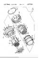
- FIG. 1is an exploded perspective view of the members of the electrical connector of the present invention.
- FIG. 2is a cross-sectional view of the matable parts of the electrical connector of FIG. 1 in position for matable engagement.
- FIG. 3is a part rear elevational view showing a contact-carrying insert as it is being latchably positioned in its housing member.
- FIG. 4is a cross-sectional view of FIG. 3.
- FIG. 5is a view similar to FIG. 3 showing the contact-carrying insert latchably secured in its housing member.
- FIG. 6is a cross-sectional view of FIG. 5.
- FIG. 7is a rear elevational view of an alternative embodiment of the present invention.
- FIGS. 1-6illustrate electrical connector 10 which includes electrical plug 12 and electrical receptacle 14. As can be discerned, electrical connector 10 is preferably of circular configuration. Electrical plug 12 includes a housing member 16 which includes a mounting flange 18, an outer section 20, and an inner section 22. Outer section 20 has threads 24 on its outer surface and a bore 26 on its inner surface. Keyways 28 are disposed in bore 26.
- Inner section 22 of housing member 16has a bore 30 out of which extend projections 32 at spaced locations along bore 30 which define key members.
- a latching projection 34is located on the inner ends of projections 32.
- An internal flange 36is located in housing member 16 between bores 26 and 30.
- Contact-carrying insert 38is molded from a suitable dielectric plastic material and it includes passageways 40 extending therethrough which have electrical receptacles 42 of conventional design secured therein. Electrical receptacles 42 include electrical posts 44 which extend through holes 46 in a sealing member 48 which is secured onto insert 38. Electrical posts 44 are to be soldered to appropriate circuits on a printed circuit board (not shown) for electrical connection therewith. Electrical receptacles 42 can be terminated to electrical conductors in accordance with conventional terminating practices if desired.
- Insert 38has outer section 50 and inner section 52 with a stop surface 54 therebetween.
- Grooves 56extend along the length of insert 38 and they are positioned therearound in coincidence with key projections 32 of housing member 16.
- the bottoms of grooves 56have concave section 58 therealong.
- Flexible latching members 60are located in outer section 50 along a section of each groove 56. They have beveled surfaces 62 at their leading ends.
- electrical receptacles 42are secured in passageways 40 and contact-carrying insert 38 has grooves 56 positioned in alignment with key projections 32 whereupon insert 38 is moved axially along housing member 16.
- the beveled surfaces of latching projections 34engage beveled surfaces 62 of flexible latching members 60 to facilitate the movement of latching members 60 thereover and concave sections 58 enable flexible latching members 60 to flex thereinto in order to enable latching members 60 to move completely along latching projections 34 until insert 38 is completely housed in housing member 16 as illustrated in FIG.
- latching members 60have moved outwardly into engagement with the bore of flange 36 due to the flexible nature of latching members 60 and into latching position with latching projections 34 as illustrated in FIGS. 2 and 6.
- Electrical receptacle 14includes metal housing member 64 having an outer section 66 and an inner section 68.
- Outer section 66has a bore 70 and key projections 72 on its outer surface at spaced locations therearound for matable engagement with keyways 28 in plug housing member 16 to assure proper mating engagement therebetween.
- Inner section 68 of housing member 64includes a bore 74 which contains spaced projections 76 therearound in the same manner as spaced projections 32 in bore 30 of housing member 16.
- Latching projections 78are located on the inner ends of projections 76 in the same manner as latching projections 34 of housing member 16.
- a stop surface 80is located at the junction of bores 70 and 74.
- a metal coupling ring 82is freely mounted onto housing member 64 for free rotation relative thereto and it includes threads 84 for matable engagement with threads 24 to couple housing members 16 and 64 together and securing same in a matably engaged condition.
- Housing member 64includes a flange 86 against which a flange 88 on coupling ring 82 engages and a snap ring 90 is disposed in groove 92 of housing member 64 to retain coupling ring 82 in position on housing member 64.
- a plastic rod 94is secured across threads 84 adjacent the inner ends thereof for engagement with a groove 96 adjacent the outer end of threads 84 to provide a tactile and audible means to indicate the fully-mated condition of plug 12 and receptacle 14 along with the electrical connection between the electrical receptacle and electrical pins therein.
- This arrangementis completely disclosed in U.S. patent application Ser. No. 345,962 filed Feb. 5, 1982, the disclosure of which is completely incorporated herein by reference.
- This rod and groove audible and tactile arrangementalso maintains the plug and receptacle in matable engagement in the presence of vibration.
- Contact-carrying insert 98is similar in construction to that of contact-carrying insert 38 in that it has an outer section 100 which fits within bore 70 of outer section 66 of housing member 64 and an inner section 102 which fits within bore 74 of inner section 68.
- Passageways 106extend through insert 98 in which are secured electrical pins 108 which electrically mate with respective electrical receptacles 42. Electrical pins 108 are terminated to electrical conductors 110 in accordance with conventional terminating practices.
- Grooves 112extend through insert 98 and have concave sections 114 in the bottom surfaces thereof in the same manner as grooves 56 of insert 38, and grooves 112 are located in coincidence with keying projections 76 in bore 74 to enable insert 98 to be positioned in housing member 64.
- Each of grooves 112includes a flexible latching member 116 having a beveled surface 118 and flexible latching members 116 function in the same manner as flexible latching members 60 enabling them to move along the beveled surfaces of latching projections 78 into latching engagement therewith as illustrated in FIG. 2 in the same manner as latching members 60.
- Latching members 60 and 116are integral with respective inserts 38 and 98, thereby precluding the need for snap rings, rods, or other similar securing devices to secure the contact-carrying inserts in position in their respective housing members.
- the arrangement of grooves 56 on insert 38 relative to keying projections 32 and the same arrangement of grooves 112 in insert 98 relative to keying projections 76 of housing member 64assures the proper orientation of inserts 38 and 98 in respective housing members 16 and 64 so that electrical receptacles 42 properly interconnect with electrical pins 108 so that the proper electrical circuits are interconnected when housing members 16 and 64 are interconnected through keyways 28 and key projections 72.
- each contact-carrying insert 120 for the electrical receptacles and electrical pinscontains flexible latching members 122 in opposed grooves 124 which are in engagement with latching projections 126 located on the inner ends of keying projections 128 of housing member 130 which latchably secures insert 120 within housing member 130.
- the remaining grooves 132 of insert 120do not contain any flexible latching members but they do cooperate with keying projections 128 when insert 120 is positioned in housing member 130.
- insert 98can be provided with a hood section extending outwardly from front surface 134 and spaced inwardly from outer section 66 of housing 64 to mate with outer section 50 of insert 38, and the hood section of insert 98 along with outer section 50 of insert 38 would be provided with a keying arrangement to make certain that proper mating engagement therebetween takes place in the same way as the plug and receptacle of the invention as disclosed in U.S. patent application Ser. No. 235,455, filed Feb. 18, 1981 of which the disclosure is incorporated by reference herein. In this arrangement, both the housing members and the inserts would be provided with keying arrangements to polarize the mating engagement therebetween.
Landscapes
- Details Of Connecting Devices For Male And Female Coupling (AREA)
- Connector Housings Or Holding Contact Members (AREA)
Abstract
Description
This invention relates to electrical connectors and more particularly to a polarizing and latch arrangement for latching contact-carrying inserts into connector housing members and defining a polarizing arrangement between the matable inserts.
Contact-carrying inserts of some electrical connectors are typically secured in their housing members by use of snap rings or pins. The insert that is secured in a housing member via a snap ring is oriented in the housing member by an orienting arrangement between the insert and the housing member against a stop surface and the snap ring is snapped into an inside annular groove in the housing member securing the insert therein. Pins are then used to secure the other contact-carrying insert in the other housing member, but the other insert has to be secured in the other housing member in such an angular orientation relative to the other housing member so as to correspond to the angular orientation of the first-mentioned insert relative to its housing member so that the polarizing arrangement therebetween is properly aligned for matable engagement thereof.
Such an arrangement has proven to be satisfactory, but use of snap rings and pins requires extra parts, requires machining a groove in the housing member in which the snap ring is to be disposed, constitutes a problem in inserting the snap ring in its groove, and requires properly orienting the other insert in the other housing member prior to securing the pins therein so that coincidence of orientation between the matable inserts and housing members takes place to assure matable engagement therebetween.
According to the present invention, an electrical connector comprises matable housing members and contact-carrying inserts. Matable electrical contact members are secured in passageways in each of the inserts and a coupling member holds the housing members, contact-carrying inserts, and electrical contact members in matable engagement. The housing members and the contact-carrying inserts include projections and flexible latching members to latchably secure the contact-carrying inserts in polarized positions in the housing members for proper matable engagement with each other.
According to another aspect of the present invention, the flexible latching members including the polarizing areas of the contact-carrying inserts can be oriented relative to their respective housing members by angular selection to assure mating engagement between only these housing members and inserts so that proper electrical interconnection is made between electrical circuits.
FIG. 1 is an exploded perspective view of the members of the electrical connector of the present invention.
FIG. 2 is a cross-sectional view of the matable parts of the electrical connector of FIG. 1 in position for matable engagement.
FIG. 3 is a part rear elevational view showing a contact-carrying insert as it is being latchably positioned in its housing member.
FIG. 4 is a cross-sectional view of FIG. 3.
FIG. 5 is a view similar to FIG. 3 showing the contact-carrying insert latchably secured in its housing member.
FIG. 6 is a cross-sectional view of FIG. 5.
FIG. 7 is a rear elevational view of an alternative embodiment of the present invention.
FIGS. 1-6 illustrate electrical connector 10 which includeselectrical plug 12 andelectrical receptacle 14. As can be discerned, electrical connector 10 is preferably of circular configuration.Electrical plug 12 includes ahousing member 16 which includes a mounting flange 18, anouter section 20, and aninner section 22.Outer section 20 hasthreads 24 on its outer surface and abore 26 on its inner surface. Keyways 28 are disposed inbore 26.
Contact-carryinginsert 38 is molded from a suitable dielectric plastic material and it includespassageways 40 extending therethrough which haveelectrical receptacles 42 of conventional design secured therein.Electrical receptacles 42 include electrical posts 44 which extend throughholes 46 in a sealingmember 48 which is secured ontoinsert 38. Electrical posts 44 are to be soldered to appropriate circuits on a printed circuit board (not shown) for electrical connection therewith.Electrical receptacles 42 can be terminated to electrical conductors in accordance with conventional terminating practices if desired.
In assembly,electrical receptacles 42 are secured inpassageways 40 and contact-carryinginsert 38 hasgrooves 56 positioned in alignment withkey projections 32 whereuponinsert 38 is moved axially alonghousing member 16. Asinsert 38 is moved withinhousing member 16, the beveled surfaces oflatching projections 34 engagebeveled surfaces 62 offlexible latching members 60 to facilitate the movement of latchingmembers 60 thereover andconcave sections 58 enableflexible latching members 60 to flex thereinto in order to enablelatching members 60 to move completely alonglatching projections 34 untilinsert 38 is completely housed inhousing member 16 as illustrated in FIG. 2 withouter section 50 ofinsert 38 disposed inouter section 20 ofhousing member 16, andinner section 52 ofinsert 38 is disposed ininner section 22 ofhousing member 16 with stop surface 54 in engagement withinternal flange 36. In this position,latching members 60 have moved outwardly into engagement with the bore offlange 36 due to the flexible nature oflatching members 60 and into latching position withlatching projections 34 as illustrated in FIGS. 2 and 6.
Ametal coupling ring 82 is freely mounted onto housing member 64 for free rotation relative thereto and it includesthreads 84 for matable engagement withthreads 24 to couplehousing members 16 and 64 together and securing same in a matably engaged condition. Housing member 64 includes aflange 86 against which a flange 88 oncoupling ring 82 engages and asnap ring 90 is disposed in groove 92 of housing member 64 to retaincoupling ring 82 in position on housing member 64. Aplastic rod 94 is secured acrossthreads 84 adjacent the inner ends thereof for engagement with agroove 96 adjacent the outer end ofthreads 84 to provide a tactile and audible means to indicate the fully-mated condition ofplug 12 andreceptacle 14 along with the electrical connection between the electrical receptacle and electrical pins therein. This arrangement is completely disclosed in U.S. patent application Ser. No. 345,962 filed Feb. 5, 1982, the disclosure of which is completely incorporated herein by reference. This rod and groove audible and tactile arrangement also maintains the plug and receptacle in matable engagement in the presence of vibration.
Contact-carryinginsert 98 is similar in construction to that of contact-carrying insert 38 in that it has anouter section 100 which fits within bore 70 ofouter section 66 of housing member 64 and aninner section 102 which fits withinbore 74 ofinner section 68. Astop surface 104 at the junction ofouter section 100 andinner section 102 engagesstop surface 80 in housing member 64 to limit inner movement ofinsert 98 within housing member 64. Passageways 106 extend throughinsert 98 in which are securedelectrical pins 108 which electrically mate with respectiveelectrical receptacles 42.Electrical pins 108 are terminated toelectrical conductors 110 in accordance with conventional terminating practices.
Whereas theinserts flexible latching members groove flexible latching members 122 inopposed grooves 124 which are in engagement withlatching projections 126 located on the inner ends ofkeying projections 128 ofhousing member 130 which latchably secures insert 120 withinhousing member 130. Theremaining grooves 132 ofinsert 120 do not contain any flexible latching members but they do cooperate withkeying projections 128 wheninsert 120 is positioned inhousing member 130. The arrangement of FIG. 7 enables contact-carryinginserts 120 of each of the housing members to be oriented in six different angular orientations relative tohousing member 130 when the connector housing members are mated together to make certain that the electrical receptacles and electrical pins are properly interconnected.
If desired,insert 98 can be provided with a hood section extending outwardly fromfront surface 134 and spaced inwardly fromouter section 66 of housing 64 to mate withouter section 50 ofinsert 38, and the hood section ofinsert 98 along withouter section 50 ofinsert 38 would be provided with a keying arrangement to make certain that proper mating engagement therebetween takes place in the same way as the plug and receptacle of the invention as disclosed in U.S. patent application Ser. No. 235,455, filed Feb. 18, 1981 of which the disclosure is incorporated by reference herein. In this arrangement, both the housing members and the inserts would be provided with keying arrangements to polarize the mating engagement therebetween.
Claims (4)
1. An insert-in-housing assembly for an electrical connector comprising a housing member, and a contact-carrying insert member latchably securable therein containing one or more electrical contact members, characterized in that:
said contact-carrying insert member has an outer section having integral flexible latching means therearound, and said insert member has grooves underlying said integral flexible latching means,
said housing member has an inner section having keying projections on each of which is located a latching projection;
said keying projections correspond with said grooves and are matably engageable therewith to position said insert member in said housing member;
said integral flexible latching means is capable of being flexed by said latching projections into said grooves as said latching projections move thereover during assembly of said insert member into said housing member and thereafter returning to an unflexed condition latchably engaging said latching projections when said insert member is in a fully mated condition in said housing;
2. An electrical connector assembly as set forth in claim 1 wherein said insert member includes a pair of opposing ones of said grooves and said integral flexible latching means with said grooves being matably engageable with said keying projections thereby selectively positioning said insert member in said respective housing member relative thereto for proper matable engagement of said electrical members.
3. An assembly for an electrical connector as set forth in claim 1 characterized in that said integral flexible latching means and said latching projections have cooperating beveled surfaces enabling them to move easily over each other during positioning of said contact-carrying insert member into said housing member.
4. An assembly for an electrical connector as set forth in claim 1 characterized in that bottoms of said grooves have concave sections enabling said integral flexible latching means to flex thereinto as said integral flexible latching means moves along said latching projections.
Priority Applications (1)
| Application Number | Priority Date | Filing Date | Title |
|---|---|---|---|
| US06/351,560US4477022A (en) | 1982-02-23 | 1982-02-23 | Polarizing and latch arrangement for an electrical connector |
Applications Claiming Priority (1)
| Application Number | Priority Date | Filing Date | Title |
|---|---|---|---|
| US06/351,560US4477022A (en) | 1982-02-23 | 1982-02-23 | Polarizing and latch arrangement for an electrical connector |
Publications (1)
| Publication Number | Publication Date |
|---|---|
| US4477022Atrue US4477022A (en) | 1984-10-16 |
Family
ID=23381406
Family Applications (1)
| Application Number | Title | Priority Date | Filing Date |
|---|---|---|---|
| US06/351,560Expired - Fee RelatedUS4477022A (en) | 1982-02-23 | 1982-02-23 | Polarizing and latch arrangement for an electrical connector |
Country Status (1)
| Country | Link |
|---|---|
| US (1) | US4477022A (en) |
Cited By (28)
| Publication number | Priority date | Publication date | Assignee | Title |
|---|---|---|---|---|
| US4571014A (en)* | 1984-05-02 | 1986-02-18 | At&T Bell Laboratories | High frequency modular connector |
| US4759729A (en)* | 1984-11-06 | 1988-07-26 | Adc Telecommunications, Inc. | Electrical connector apparatus |
| US4789360A (en)* | 1986-11-03 | 1988-12-06 | Amphenol Corporation | Electrical connector with rear removable contacts |
| US4818237A (en)* | 1987-09-04 | 1989-04-04 | Amp Incorporated | Modular plug-in connection means for flexible power supply of electronic apparatus |
| US4820204A (en)* | 1986-12-12 | 1989-04-11 | Amp Incorporated | Modular electrical connector assembly |
| US5145411A (en)* | 1991-08-14 | 1992-09-08 | Amp Incorporated | Connector insert retention system |
| US5376015A (en)* | 1992-02-22 | 1994-12-27 | Karl Lomberg Gmbh & Co. | Screw-on electrical connector assembly |
| US5924899A (en)* | 1997-11-19 | 1999-07-20 | Berg Technology, Inc. | Modular connectors |
| US6042428A (en)* | 1998-06-22 | 2000-03-28 | Itt Manufacturing Enterprises, Inc. | Connector insert retention |
| US6056599A (en)* | 1996-10-22 | 2000-05-02 | The Whitaker Corporation | Electrical connector with matable contact assembly |
| US6065999A (en)* | 1997-09-30 | 2000-05-23 | The Whitaker Corporation | Secondary locking shroud for an electrical connector |
| US6109976A (en)* | 1998-07-10 | 2000-08-29 | Berg Technology, Inc. | Modular high speed connector |
| US6135800A (en)* | 1998-12-22 | 2000-10-24 | Conxall Corporation | Anti-rotational electrical connector |
| US6336822B1 (en)* | 1999-01-26 | 2002-01-08 | Veam S.R.L. | Handle operated power connector |
| US6540558B1 (en) | 1995-07-03 | 2003-04-01 | Berg Technology, Inc. | Connector, preferably a right angle connector, with integrated PCB assembly |
| US6666701B1 (en) | 2002-07-22 | 2003-12-23 | Signet Scientific Company | Bayonet-type electrical connector assembly |
| US6811422B1 (en)* | 1999-05-21 | 2004-11-02 | Fci | Electrical connector with pressure spring and lever |
| US6843657B2 (en) | 2001-01-12 | 2005-01-18 | Litton Systems Inc. | High speed, high density interconnect system for differential and single-ended transmission applications |
| US20050032423A1 (en)* | 2003-08-05 | 2005-02-10 | Ward Bobby Gene | Terminal position assurance with forward interlocking face keying |
| US6910897B2 (en) | 2001-01-12 | 2005-06-28 | Litton Systems, Inc. | Interconnection system |
| US6979202B2 (en) | 2001-01-12 | 2005-12-27 | Litton Systems, Inc. | High-speed electrical connector |
| US20080188119A1 (en)* | 2007-02-02 | 2008-08-07 | Japan Aviation Electronics Industry, Limited | Connector and device equipped with the same |
| US9780485B2 (en)* | 2015-06-01 | 2017-10-03 | Souriau | Bayonet type locking ring of a circular electrical connector |
| US20180043848A1 (en)* | 2016-08-10 | 2018-02-15 | Yazaki Corporation | Connector |
| US20200183037A1 (en)* | 2017-06-09 | 2020-06-11 | Magseis Ff Llc | Seismic data acquisition unit |
| US20210162434A1 (en)* | 2019-12-02 | 2021-06-03 | Exel Industries | Electrostatic rotary projector for coating product and spraying installation comprising such a projector |
| US20210222809A1 (en)* | 2020-01-17 | 2021-07-22 | Volansi, Inc | Aircraft tail lock |
| USD1070786S1 (en)* | 2019-11-19 | 2025-04-15 | Link S.R.L. | Insert for connector |
Citations (8)
| Publication number | Priority date | Publication date | Assignee | Title |
|---|---|---|---|---|
| US3008116A (en)* | 1959-04-27 | 1961-11-07 | Cannon Electric Co | Moisture-proof quick-disconnect device |
| US3116960A (en)* | 1959-08-03 | 1964-01-07 | Malco Mfg Co | Electrical socket |
| US3202956A (en)* | 1963-08-12 | 1965-08-24 | Bendix Corp | Electrical connector |
| US3614711A (en)* | 1969-10-15 | 1971-10-19 | Bunker Ramo | Electrical connector having adjustable keying |
| DE2807366A1 (en)* | 1977-02-22 | 1978-08-24 | Bunker Ramo | CONNECTOR ARRANGEMENT |
| US4193655A (en)* | 1978-07-20 | 1980-03-18 | Amp Incorporated | Field repairable connector assembly |
| US4268103A (en)* | 1979-02-02 | 1981-05-19 | The Bendix Corporation | Electrical connector assembly having anti-decoupling mechanism |
| US4322121A (en)* | 1979-02-06 | 1982-03-30 | Bunker Ramo Corporation | Screw-coupled electrical connectors |
- 1982
- 1982-02-23USUS06/351,560patent/US4477022A/ennot_activeExpired - Fee Related
Patent Citations (8)
| Publication number | Priority date | Publication date | Assignee | Title |
|---|---|---|---|---|
| US3008116A (en)* | 1959-04-27 | 1961-11-07 | Cannon Electric Co | Moisture-proof quick-disconnect device |
| US3116960A (en)* | 1959-08-03 | 1964-01-07 | Malco Mfg Co | Electrical socket |
| US3202956A (en)* | 1963-08-12 | 1965-08-24 | Bendix Corp | Electrical connector |
| US3614711A (en)* | 1969-10-15 | 1971-10-19 | Bunker Ramo | Electrical connector having adjustable keying |
| DE2807366A1 (en)* | 1977-02-22 | 1978-08-24 | Bunker Ramo | CONNECTOR ARRANGEMENT |
| US4193655A (en)* | 1978-07-20 | 1980-03-18 | Amp Incorporated | Field repairable connector assembly |
| US4268103A (en)* | 1979-02-02 | 1981-05-19 | The Bendix Corporation | Electrical connector assembly having anti-decoupling mechanism |
| US4322121A (en)* | 1979-02-06 | 1982-03-30 | Bunker Ramo Corporation | Screw-coupled electrical connectors |
Cited By (40)
| Publication number | Priority date | Publication date | Assignee | Title |
|---|---|---|---|---|
| US4571014A (en)* | 1984-05-02 | 1986-02-18 | At&T Bell Laboratories | High frequency modular connector |
| US4759729A (en)* | 1984-11-06 | 1988-07-26 | Adc Telecommunications, Inc. | Electrical connector apparatus |
| US4789360A (en)* | 1986-11-03 | 1988-12-06 | Amphenol Corporation | Electrical connector with rear removable contacts |
| US4820204A (en)* | 1986-12-12 | 1989-04-11 | Amp Incorporated | Modular electrical connector assembly |
| US4818237A (en)* | 1987-09-04 | 1989-04-04 | Amp Incorporated | Modular plug-in connection means for flexible power supply of electronic apparatus |
| US5145411A (en)* | 1991-08-14 | 1992-09-08 | Amp Incorporated | Connector insert retention system |
| US5376015A (en)* | 1992-02-22 | 1994-12-27 | Karl Lomberg Gmbh & Co. | Screw-on electrical connector assembly |
| US6540558B1 (en) | 1995-07-03 | 2003-04-01 | Berg Technology, Inc. | Connector, preferably a right angle connector, with integrated PCB assembly |
| US6056599A (en)* | 1996-10-22 | 2000-05-02 | The Whitaker Corporation | Electrical connector with matable contact assembly |
| US6065999A (en)* | 1997-09-30 | 2000-05-23 | The Whitaker Corporation | Secondary locking shroud for an electrical connector |
| US5924899A (en)* | 1997-11-19 | 1999-07-20 | Berg Technology, Inc. | Modular connectors |
| US6102747A (en)* | 1997-11-19 | 2000-08-15 | Berg Technology, Inc. | Modular connectors |
| US6042428A (en)* | 1998-06-22 | 2000-03-28 | Itt Manufacturing Enterprises, Inc. | Connector insert retention |
| US6109976A (en)* | 1998-07-10 | 2000-08-29 | Berg Technology, Inc. | Modular high speed connector |
| US6135800A (en)* | 1998-12-22 | 2000-10-24 | Conxall Corporation | Anti-rotational electrical connector |
| US6336822B1 (en)* | 1999-01-26 | 2002-01-08 | Veam S.R.L. | Handle operated power connector |
| US6811422B1 (en)* | 1999-05-21 | 2004-11-02 | Fci | Electrical connector with pressure spring and lever |
| US6910897B2 (en) | 2001-01-12 | 2005-06-28 | Litton Systems, Inc. | Interconnection system |
| US6843657B2 (en) | 2001-01-12 | 2005-01-18 | Litton Systems Inc. | High speed, high density interconnect system for differential and single-ended transmission applications |
| US6979202B2 (en) | 2001-01-12 | 2005-12-27 | Litton Systems, Inc. | High-speed electrical connector |
| US7019984B2 (en) | 2001-01-12 | 2006-03-28 | Litton Systems, Inc. | Interconnection system |
| US7056128B2 (en) | 2001-01-12 | 2006-06-06 | Litton Systems, Inc. | High speed, high density interconnect system for differential and single-ended transmission systems |
| US7101191B2 (en) | 2001-01-12 | 2006-09-05 | Winchester Electronics Corporation | High speed electrical connector |
| US6666701B1 (en) | 2002-07-22 | 2003-12-23 | Signet Scientific Company | Bayonet-type electrical connector assembly |
| US20050032423A1 (en)* | 2003-08-05 | 2005-02-10 | Ward Bobby Gene | Terminal position assurance with forward interlocking face keying |
| US7077702B2 (en)* | 2003-08-05 | 2006-07-18 | Tyco Electronics Corporation | Terminal position assurance with forward interlocking face keying |
| US20080188119A1 (en)* | 2007-02-02 | 2008-08-07 | Japan Aviation Electronics Industry, Limited | Connector and device equipped with the same |
| US7507125B2 (en)* | 2007-02-02 | 2009-03-24 | Japan Aviation Electronics Industry Limited | Connector and device equipped with the same |
| US9780485B2 (en)* | 2015-06-01 | 2017-10-03 | Souriau | Bayonet type locking ring of a circular electrical connector |
| US20180043848A1 (en)* | 2016-08-10 | 2018-02-15 | Yazaki Corporation | Connector |
| CN107732545A (en)* | 2016-08-10 | 2018-02-23 | 矢崎总业株式会社 | Connector |
| US10106109B2 (en)* | 2016-08-10 | 2018-10-23 | Yazaki Corporation | Charging inlet connector assembled to a vehicle body of a vehicle mounted with a battery |
| CN107732545B (en)* | 2016-08-10 | 2020-02-11 | 矢崎总业株式会社 | Connector with a locking member |
| DE102017213659B4 (en) | 2016-08-10 | 2023-06-22 | Yazaki Corporation | connector |
| US20200183037A1 (en)* | 2017-06-09 | 2020-06-11 | Magseis Ff Llc | Seismic data acquisition unit |
| US11867860B2 (en)* | 2017-06-09 | 2024-01-09 | Magseis Ff Llc | Seismic data acquisition unit |
| USD1070786S1 (en)* | 2019-11-19 | 2025-04-15 | Link S.R.L. | Insert for connector |
| US20210162434A1 (en)* | 2019-12-02 | 2021-06-03 | Exel Industries | Electrostatic rotary projector for coating product and spraying installation comprising such a projector |
| US20210222809A1 (en)* | 2020-01-17 | 2021-07-22 | Volansi, Inc | Aircraft tail lock |
| US12085210B2 (en)* | 2020-01-17 | 2024-09-10 | Sierra Nevada Company, Llc | Aircraft tail lock |
Similar Documents
| Publication | Publication Date | Title |
|---|---|---|
| US4477022A (en) | Polarizing and latch arrangement for an electrical connector | |
| EP0440447B1 (en) | Interconnectable components employing a multi-positionable key | |
| US5167542A (en) | Interconnectable components employing a multi-positionable key | |
| US4938718A (en) | Cylindrical connector keying means | |
| KR950002037B1 (en) | Floating mounting means for electrical connector assembly | |
| US5417590A (en) | Plug and socket electrical connector system | |
| EP0415489B1 (en) | Mountable connector for cable assembly | |
| US4443052A (en) | Means to indicate fully-mated condition of electrical connector | |
| US5273462A (en) | Connector keying system | |
| US4479691A (en) | Connector assembly | |
| US6450834B1 (en) | Panel mounting system for electrical connectors | |
| US4640567A (en) | Detachable sealed multicontact electrical connector | |
| EP0183830A1 (en) | Printed circuit board header having coaxial sockets therein and matable coaxial plug housing | |
| HK1000400B (en) | Mountable connector for cable assembly | |
| US5240431A (en) | Waterproof connector | |
| US3763458A (en) | Terminal retaining connector block | |
| US4531801A (en) | Plug and receptacle connector locking means | |
| US3535675A (en) | Side mount connector | |
| CA1153437A (en) | Electrical connector coupling member | |
| US5160279A (en) | Double lock connector | |
| JPH0244470Y2 (en) | ||
| EP0994533A1 (en) | Connector system with polarizing key mechanism | |
| US4934963A (en) | Electrical connector | |
| US4936793A (en) | Locking device for connector | |
| US5154630A (en) | Plug connector assembly |
Legal Events
| Date | Code | Title | Description |
|---|---|---|---|
| AS | Assignment | Owner name:AMP INCORPORATED, P.O. BOX 3608, HARRISBURG, PA. 1 Free format text:ASSIGNMENT OF ASSIGNORS INTEREST.;ASSIGNORS:SHUEY, JOHN R.;WIDENER, DONALD R.;REEL/FRAME:003993/0380 Effective date:19820219 Owner name:AMP INCORPORATED,PENNSYLVANIA Free format text:ASSIGNMENT OF ASSIGNORS INTEREST;ASSIGNORS:SHUEY, JOHN R.;WIDENER, DONALD R.;REEL/FRAME:003993/0380 Effective date:19820219 | |
| FEPP | Fee payment procedure | Free format text:PAYOR NUMBER ASSIGNED (ORIGINAL EVENT CODE: ASPN); ENTITY STATUS OF PATENT OWNER: LARGE ENTITY | |
| FPAY | Fee payment | Year of fee payment:4 | |
| FPAY | Fee payment | Year of fee payment:8 | |
| REMI | Maintenance fee reminder mailed | ||
| LAPS | Lapse for failure to pay maintenance fees | ||
| FP | Lapsed due to failure to pay maintenance fee | Effective date:19961016 | |
| STCH | Information on status: patent discontinuation | Free format text:PATENT EXPIRED DUE TO NONPAYMENT OF MAINTENANCE FEES UNDER 37 CFR 1.362 |