US4475551A - Arrhythmia detection and defibrillation system and method - Google Patents
Arrhythmia detection and defibrillation system and methodDownload PDFInfo
- Publication number
- US4475551A US4475551AUS06/414,353US41435382AUS4475551AUS 4475551 AUS4475551 AUS 4475551AUS 41435382 AUS41435382 AUS 41435382AUS 4475551 AUS4475551 AUS 4475551A
- Authority
- US
- United States
- Prior art keywords
- circuit
- heart
- sensing
- ecg
- output
- Prior art date
- Legal status (The legal status is an assumption and is not a legal conclusion. Google has not performed a legal analysis and makes no representation as to the accuracy of the status listed.)
- Expired - Lifetime
Links
- 238000000034methodMethods0.000titleclaimsabstractdescription48
- 238000001514detection methodMethods0.000titleclaimsabstractdescription28
- 206010003119arrhythmiaDiseases0.000titleabstractdescription9
- 230000006793arrhythmiaEffects0.000titleabstractdescription9
- 208000001871TachycardiaDiseases0.000claimsabstractdescription51
- 230000006794tachycardiaEffects0.000claimsabstractdescription51
- 230000033764rhythmic processEffects0.000claimsabstractdescription40
- 230000000747cardiac effectEffects0.000claimsabstractdescription39
- 230000002159abnormal effectEffects0.000claimsabstractdescription38
- 230000001862defibrillatory effectEffects0.000claimsabstractdescription33
- 238000012544monitoring processMethods0.000claimsabstractdescription29
- 208000003663ventricular fibrillationDiseases0.000claimsdescription24
- 230000002401inhibitory effectEffects0.000claimsdescription4
- 230000001788irregularEffects0.000claimsdescription3
- 238000001914filtrationMethods0.000claimsdescription2
- 206010061592cardiac fibrillationDiseases0.000abstractdescription7
- 230000002600fibrillogenic effectEffects0.000abstractdescription7
- 239000003990capacitorSubstances0.000description19
- 238000010586diagramMethods0.000description12
- 230000035939shockEffects0.000description8
- 230000000694effectsEffects0.000description5
- 238000011161developmentMethods0.000description4
- 238000007599dischargingMethods0.000description2
- 230000028161membrane depolarizationEffects0.000description2
- 230000000246remedial effectEffects0.000description2
- 230000000630rising effectEffects0.000description2
- 230000001960triggered effectEffects0.000description2
- 210000002620vena cava superiorAnatomy0.000description2
- 230000002861ventricularEffects0.000description2
- 206010047302ventricular tachycardiaDiseases0.000description2
- 230000005856abnormalityEffects0.000description1
- 230000009286beneficial effectEffects0.000description1
- 239000008280bloodSubstances0.000description1
- 210000004369bloodAnatomy0.000description1
- 210000002318cardiaAnatomy0.000description1
- 238000013194cardioversionMethods0.000description1
- 238000007796conventional methodMethods0.000description1
- 238000013461designMethods0.000description1
- 238000010304firingMethods0.000description1
- 208000019622heart diseaseDiseases0.000description1
- 238000002955isolationMethods0.000description1
- 238000005086pumpingMethods0.000description1
- 230000035945sensitivityEffects0.000description1
- 230000006641stabilisationEffects0.000description1
- 238000011105stabilizationMethods0.000description1
Images


Classifications
- A—HUMAN NECESSITIES
- A61—MEDICAL OR VETERINARY SCIENCE; HYGIENE
- A61N—ELECTROTHERAPY; MAGNETOTHERAPY; RADIATION THERAPY; ULTRASOUND THERAPY
- A61N1/00—Electrotherapy; Circuits therefor
- A61N1/18—Applying electric currents by contact electrodes
- A61N1/32—Applying electric currents by contact electrodes alternating or intermittent currents
- A61N1/38—Applying electric currents by contact electrodes alternating or intermittent currents for producing shock effects
- A61N1/39—Heart defibrillators
- A61N1/3956—Implantable devices for applying electric shocks to the heart, e.g. for cardioversion
- A—HUMAN NECESSITIES
- A61—MEDICAL OR VETERINARY SCIENCE; HYGIENE
- A61N—ELECTROTHERAPY; MAGNETOTHERAPY; RADIATION THERAPY; ULTRASOUND THERAPY
- A61N1/00—Electrotherapy; Circuits therefor
- A61N1/18—Applying electric currents by contact electrodes
- A61N1/32—Applying electric currents by contact electrodes alternating or intermittent currents
- A61N1/38—Applying electric currents by contact electrodes alternating or intermittent currents for producing shock effects
- A61N1/39—Heart defibrillators
- A61N1/3987—Heart defibrillators characterised by the timing or triggering of the shock
Definitions
- the present inventionrelates to an arrhythmia detection system and method, and more particularly to an improved system and method for defibrillating the heart of a patient when the patient experiences life-threatening fibrillation.
- an apex electrodeis applied to the external intrapericardial or extrapericardial surface of the heart, and acts against a base electrode which can be either similarly conformal or in the form of an intravascular catheter.
- Such electrode arrangements of the prior artas disclosed in the aforementioned patent of Heilman et al, can employ independent pacing tips associated with either a base electrode or an apex electrode, or both.
- the prior art probability density function detectorwhen not optimally adjusted, can be "triggered” not only by actual ventricular fibrillation, but also by some forms of high rate ventricular tachycardia, and low rate ventricular tachycardia as well, particularly in the presence of ventricular conduction abnormalities. Unlike ventricular fibrillation, such high rate and low rate tachycardias are characterized by regular R-waves occurring at generally stable rates.
- inventive system and method herein disclosedamounts to a "backup" technique by means of which high rate tachycardia is treated by issuance of a defibrillating shock to the patient, while low rate tachycardia is not so treated.
- an arrhythmia detection system and methodand more particularly an improved system and method for defibrillating a heart which is undergoing abnormal cardiac rhythm, the improved system and method employing a technique for distinguishing between ventricular fibrillation and high rate tachycardia, on the one hand, and low rate tachycardia, on the other hand.
- the system and method of the present inventionbesides utilizing the probability density function technique to determine the presence of abnormal cardia rhythm, also employs heart rate sensing for the purpose of distinguishing between ventricular fibrillation and high rate tachycardia, on the one hand, the latter being indicated by a heart rate above a predetermined threshold, and low rate tachycardia, on the other hand, the latter being indicated by a heart rate falling below the predetermined threshold.
- the present inventionis implemented by a first preferred embodiment of a system, wherein a superior vena cava (or base) electrode and an apical (or patch) electrode are associated with the heart, and are employed, as in conventional in the art, not only to derive an electrocardiograph (ECG) signal, but also to apply a defibrillating shock to the heart.
- ECGelectrocardiograph
- the ECG amplifier in the first embodimentessentially provides the derivative of the heart signal as taught in U.S. Pat. No. 4,184,493.
- the differentiated ECG signalis, in this first embodiment of the invention, applied to a probability density function circuit, and to a low pass filter and a heart rate circuit, by means of which the probability density function and heart rate, respectively, are obtained.
- satisfaction of the probability density criteriathat is, determination of whether the time-averaged derivative of the ECG remains off the base line for extended periods of time
- the heart rateis above a predetermined threshold
- the defibrillating pulse generatorto issue a defibrillating shock to the heart.
- the defibrillating shockwill be issued to the heart only upon the occurrence of fibrillation or high rate tachycardia, as contrasted with non-life threatening low rate tachycardia.
- a sensing button(preferably, associated with the apical or patch electrode) is connected to the heart for use in deriving the heart rate.
- the base and apical electrodesare utilized initially to derive the ECG signal by means of which the probability density function is examined. If the probability density function indicates abnormal cardiac rhythm, a switching operation takes place, whereby the sensing button is utilized to derive an ECG signal which is further utilized to determine the heart rate. Since a very small area electrode will result in signals in which cardiac depolarizations can still be identified, even during ventricular fibrillation, a conventional R-wave detector can be used so as to provide an R-wave for heart rate sensing.
- a defibrillating shockis issued.
- a further switching operationis executed so that the base and apical electrodes may be utilized in further examining the probability density function.
- this second embodimentis provided with a timed reset capability, whereby, once the probability density function indicates abnormal cardiac rhythm, if a heart rate above the predetermined threshold is not indicated within a predetermined time, a return switch operation is automatically executed so as to permit renewed monitoring of the base and apical electrodes and examination of the resulting ECG signal vis-a-vis the probability density function.
- an object of the present inventionto provide an arrhythmia detection system and method, and more particularly an improved system and method for defibrillating a heart experiencing abnormal cardiac rhythm.
- FIG. 1is a block diagram of a first embodiment of the arrhythmia detection system of the present invention.
- FIG. 2is a detailed diagram of the heart rate circuit employed for detecting heart rate in the embodiment of FIG. 1.
- FIG. 3A and 3Bare a series of waveform diagrams utilized in describing the operation of the heart rate circuit of FIG. 2.
- FIG. 4is a block diagram of a second embodiment of the system of the present invention.
- FIG. 5is a detailed diagram of the heart rate circuit employed for detecting heart rate in the embodiment of FIG. 2.
- FIG. 6is a series of waveform diagrams utilized in describing the operation of the heart rate circuit of FIG. 5.
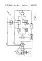
- FIG. 1is a block diagram of a first embodiment of the system.
- the system of the present invention(generally indicated by reference numeral 10) is connected to a superior vena cava (or base) electrode 12 and an apical (or patch) electrode 14, the latter being disposed in contact with the heart of the patient as is known in the prior art (see, for example, U.S. Pat. No. 4,030,509 of Heilman et al mentioned above).
- electrodes 12 and 14are connected, via an interface 16, to an ECG amplifier 18 which has inherent filtering so as to provide an approximation of the differentiated ECG.
- the ECG amplifier 18is connected both to low pass filter circuit 19 (which itself is connected to heart rate circuit 21) and to probability density function (PDF) circuit 20.
- Heart rate circuit 21is connected via its inhibit output line (INHIBIT) to the PDF circuit 20, by means of which the output line heart rate circuit 21 is able to inhibit output from the PDF circuit 20.
- the output of the PDF circuit 20is connected to defibrillation pulse generator 26, the latter being connected via the interface 16 to the electrodes 12 and 14.
- electrodes 12 and 14are employed, via the interface 16 (a conventional interface, or isolation circuit), for two purposes: (1) monitoring of heart activity via ECG amplifier 18, which develops a differentiated ECG signal output provided to PDF circuit 20 and low pass filter 21, respectively; and (2) application of a defibrillating shock from defibrillation pulse generator 26, via the interface 16, to the heart.
- PDF circuit 20monitors the probability density function of the differentiated ECG output signal of ECG amplifier 18, and, in accordance with conventional techniques (as disclosed, for example, in U.S. Pat. Nos. 4,184,493 and 4,202,340 of Langer et al), determines when abnormal cardiac rhythm of the heart exists.
- the low pass filtered ECG signalprovided as the output of low pass filter 19, is employed by rate circuit 21 to determine when the heart rate exceeds a predetermined threshold, at which time rate circuit 21 removes its inhibiting influence on PDF circuit 20.
- the PDF circuit 20upon determination of abnormal cardiac rhythm by PDF circuit 20, and of a heart rate above the predetermined threshold by rate circuit 22, the PDF circuit 20 is allowed to enable defibrillation pulse generator 26, causing the latter to apply a defibrillating shock, via interface 16, to the heart.
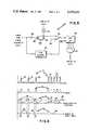
- FIG. 2is a detailed diagram of the heart rate circuit employed for detecting heart rate in the embodiment of FIG. 1, while FIGS. 3A and 3B are a series of waveform diagrams utilized in describing the operation of the heart rate circuit of FIG. 2.
- the heart rate circuit 21comprises operational amplifier OP1 (which is used as a comparator), transistors Q1 through Q4, resistors R3 through R14, capacitors C2 and C3, and diodes D1 and D2.
- OP1which is used as a comparator
- transistors Q1 through Q4transistors Q1 through Q4, resistors R3 through R14, capacitors C2 and C3, and diodes D1 and D2.
- the heart rate circuit 21 of FIG. 2functions in the following manner, with reference to the waveforms shown in FIG. 3.
- the input to ECG amplifier 18(FIG. 1) comprises an undifferentiated ECG signal, as provided by the electrodes 12 and 14.
- the undifferentiated ECG signalis represented by the waveform 100 of FIG. 3A, and is illustrated as a signal having regular R-waves and a generally stable (or uniform) rate.
- the ECG amplifier 18amplifies and filters (differentiates) the ECG signal, and the amplified and differentiated output of the ECG amplifier 18 is shown as waveform 102 in FIG. 3A.
- the amplified and differentiated ECG signal from amplifier 18is filtered, in a manner to be discussed in more detail below, by low pass filter 19 (made up of resistor Rl and capacitor Cl).
- the amplified, differentiated and filtered ECG signalis provided to the negative input of operational amplifier OP1, the positive input of which receives a reference input REF via resistor R3.
- Operational amplifier OP1is used as a comparator, and switches between low and high outputs in accordance with the relationship between the ECG input and the reference REF. More specifically, it should be noted that zero crossings in a derivative waveform (such as the output of amplifier 18 of FIG. 1) correspond to peaks in the original signal (the original ECG signal). Accordingly, low pass filter 19 of FIG. 1 filters the differentiated ECG input provided thereto in such a way that the output of operational amplifier OP1 (FIG. 2), used as a comparator, switches at the zero crossings in the derivative waveform corresponding to major peaks in the ECG input signal. The output of comparator OP1 appears as waveform 104 in FIG. 3A, and illustrates the switching action just described.
- transistor Q1has its emitter connected to one of the offset adjustment terminals of operational amplifier OP1 so as to add hysteresis to the switching threshold of the amplifier OP1.
- This hysteresisin combination with the characteristics of the low pass filter 19 of FIG. 1, has the effect of reducing the sensitivity of the heart rate circuit 21 to smaller peaks in the ECG input signal.
- the remainder of heart rate circuit 21 of FIG. 2acts as a precision timer which is responsive to the ECG peaks, as detected by and indicated by switching of the operational amplifier OP1.
- a programmable uni-junction transistor Q2is connected in series with resistor R5, the latter series combination being connected between the output of amplifier OP1 and the collector of transistor Q1.
- the gate lead of transistor Q2is connected, via resistor R4 to the output of amplifier OP1.
- programmable uni-junction transistor Q2is connected in such a way as to provide a narrow pulse to the base of a further transistor Q3 having its base connected via resistors R7 and R8 to the uni-junction transistor Q2, as shown.
- the narrow pulse thus provided to the base of transistor Q3corresponds to the rising edge of the output of amplifier OP1 (waveform 104 of FIG. 3A), and this narrow pulse is indicated by waveform 106 of FIG. 3A.
- the operation of programmable uni-junction transistor Q2, which thus provides the pulse output shown in waveform 106will be evident to those of skill in the art with respect to the utilization of such devices.
- the narrow pulse shown in waveform 106 of FIG. 3Ais also shown in FIG. 3B.
- This narrow pulseis applied to the base of transistor Q3, and turns on transistor Q3 at a frequency determined by the frequency of occurrence of the rising edges of the output of amplifier OP1, that is, in accordance with a frequency related to heart rate.
- capacitor C2will experience a voltage build-up as shown in waveform 108 of FIG. 3B. That is to say, capacitor C2 will experience a build-up of voltage under the influence of power supply V s (provided via resistors R9 and RlO), and will then discharge through transistor Q3 when that transistor is turned on by receipt of a narrow pulse (waveform 106 of FIG.
- firing of transistor Q4results in the occurrence of a negative-going pulse (waveform 114 of FIG. 3A) at the aforementioned junction between resistors R11 and R12, diode D2 and transistor Q4.
- Such negative-going pulsesare utilized to inhibit operation of the PDF circuit 20 of FIG. 1 (via the control line INHIBIT).
- these negative-going pulsesare utilized to remove charge from the integrating capacitor in the PDF circuit 20, as taught in U.S. Pat. No. 4,184,493 of Langer et al.
- PDF circuit 20(FIG. 1) is inhibited by rate circuit 21 at low heart rate, but no such inhibiting function takes place at high heart rate.
- rate circuit 21At high heart rate, the PDF circuit 20 proceeds with its normal detection operation, and enables defibrillation pulse generator 26 in accordance therewith.
- diode D2is provided for the purpose of temperature and voltage stabilization of the time interval of transistor Q4.
- interface 16is a conventional interface. More specifically, interface 16 protects the ECG amplifier 18 from the defibrillation pulses issued by generator 26, while at the same time permitting the monitoring of heart activity by ECG amplifier 18. Interface 16 is, for example, disclosed in more detail in copending application U.S. Ser. No. 215,520 of Langer, entitled “Method and Apparatus for Combining Pacing and Cardioverting Functions in a Single Implanted Device.” Moreover, the PDF circuit 20 is a conventional circuit for performing the probability density function, and is, for example, disclosed in more detail in the aforementioned U.S. Pat. Nos. 4,184,493 and 4,202,340 of Langer et al.
- FIG. 4is a block diagram of a second embodiment of the system of the present invention. Elements common to both FIGS. 1 and 4 have been identified by identical reference numerals.
- the system 30is shown connected to base and apical electrodes 12 and 14, and to a sensing button 32 (associated with apical electrode 14). More specifically, the electrodes 12 and 14 and sensing button 32 are connected, via a switch 34 and interface 16, both to the ECG amplifier 18 and the defibrillation pulse generator 26.
- ECG amplifier 18is connected, as was the case in FIG. 1, to the PDF circuit 20, but is also connected to R-wave detector 22 which is of conventional design and provides a pulse with each R-wave.
- R-wave detector 22is subsequently connected to rate circuit 23, which is shown in detail in FIG. 5 (to be discussed below).
- the output of PDF circuit 20is connected, via flip-flop 36, to one input of the AND gate 24, the other input of which is connected to the output of rate circuit 23.
- the output of flip-flop 36is connected to rate circuit 23, the input of a timed reset circuit 38 (the output of which is connected to the "reset” input of flip-flop 36), and to switch 34.
- the output of AND gate 24is connected not only to defibrillation pulse generator 26, but also to the "reset" input of flip-flop 36 and to switch 34.
- switch 34is initially in the position indicated by reference numeral 40. Therefore, in this mode (subsequently referred to as the "patch” mode), the base and apical electrodes are utilized by ECG amplifier 18 which monitors heart activity via interface 16, switch 34, and aforementioned electrodes 12 and 14. The resulting ECG signal output from amplifier 18 is provided to PDF circuit 20 (rate circuit 23 is initially in the "off” state). Detection of abnormal cardiac rhythm by PDF circuit 20 results in generation of an output, which is applied to the "set" input of flip-flop 36. When flip-flop 36 is set, existence of abnormal cardiac rhythm is "memorized", and a Q output is generated.
- the Q output of flip-flop 36is applied as an "enabling input” to AND gate 24. It is also applied as a START command to both rate circuit 23 and timed reset circuit 38. Moreover, the Q output of flip-flop 36 is provided as signal SENSE to the switch 34, resulting in actuation of switch 34 to the position indicated by reference numeral 42. This establishes the "sense" mode of operation, during which heart rate is monitored by rate circuit 23. More specifically, actuation of switch 34 to the position indicated by reference numeral 42 connects the interface 16 to the sensing button 32, so that heart rate can be monitored by rate circuit 23 via R-wave detector 22, switch 34, interface 16, and ECG amplifier 18.
- rate circuit 23was started by the Q output of flip-flop 36, the latter being issued as a result of detection of abnormal cardiac rhythm (satisfaction of the probability density function criteria) by PDF circuit 20.
- rate circuit 23If and when rate circuit 23 detects a heart rate which exceeds a predetermined threshold, it issues an output to AND gate 24 which, as enabled by the Q output of flip-flop 36, provides this output as an enabling input to defibrillation pulse generator 26. Moreover, AND gate 24 provides this output to the "reset" input of flip-flop 36 (thus, resetting flip-flop 36), and as an input signal PATCH to switch 34, actuating switch 34 to the position indicated by reference numeral 40, thus reestablishing the "patch" mode of operation of the system 30.
- defibrillation pulse generator 26issues a defibrillation pulse, via interface 16 and switch 34 (in position 40), to the base and apical electrodes 12 and 14, respectively, so as to defibrillate the heart of the patient.
- timed reset circuit 38starts the timed reset circuit 38 upon detection of abnormal cardiac rhythm by the PDF circuit 20. If, after a predetermined period of time, rate circuit 23 has not detected a heart rate above the predetermined threshold, timed reset circuit 38 automatically issues a "reset” input to flip-flop 36, and provides a further input PATCH to the switch 34, so as to actuate switch 34 to the position indicated by reference numeral 40, thus reestablishing the "patch" mode of operation.
- the system 30is provided with the beneficial feature whereby if, within a predetermined time after detection of abnormal cardiac rhythm by PDF circuit 20, heart rate is not detected as exceeding the predetermined threshold, the system 30 is returned to the "patch" mode of operation so as to permit further monitoring of the ECG signal by the PDF circuit 20. That is to say, the timed reset circuit 38 removes the enabling input from AND gate 24, turns off the rate circuit 23, and returns the switch 34 to the "patch" position (indicated by reference numeral 40). Then the PDF circuit 20 monitors the base and apical electrodes 12 and 14, respectively, via switch 34, interface 16 and ECG amplifier 18, to once again detect existence of any abnormal cardiac rhythm.
- FIG. 5is a detailed diagram of the heart rate circuit 23 of FIGS. 4, while FIG. 6 is a series of waveform diagrams describing the operation of the heart rate circuit 23 of FIG. 4.
- rate circuit 23comprises input resistor 50, NPN transistor 52, current source 54, capacitor 56, differential amplifier or comparison circuit 58, peak detector 60, shift register 62 and AND gate 64.
- ECG signals(generally indicated by reference numeral 70 of FIG. 6 and shown, for each of the two discrete segments, as having regular R-waves and a generally stable rate) are provided to R-wave detector 22 (FIG. 4), the latter generating a pulse train (generally indicated by reference numeral 75 of FIG. 6) corresponding thereto.
- this pulse train output of the R-wave detector 22is provided, via input resistor 50 (FIG. 5), to the base of NPN transistor 52.
- Transistor 52is turned on as a result of receipt of each individual pulse in pulse train 75, and is thus turned on in correspondence to detection of individual R-waves 72, 74.
- transistor 52is non-conductive, and current source 54 builds up a voltage on capacitor 56. This build-up of voltage on capacitor 56 is generally indicated by waveform 76 of FIG. 6.
- NPN transistor 52(FIG. 5) becomes conductive, and capacitor 56 discharges therethrough (see individual waveforms 78 and 80 of FIG. 6).
- current source 54is able to build the voltage across capacitor 56 to a relatively high level, exceeding a predetermined reference REF (indicated by reference numeral 86 in FIG. 6).
- REFreference numeral 86 in FIG. 6
- occurrence of R-waves at an abnormally high rateresults in discharge of capacitor 56 at a more frequent rate (as indicated by waveforms 80 of FIG. 6), and the reference REF is not exceeded.
- differential amplifier 58is provided, at its negative input, with a voltage corresponding to the voltage built up on capacitor 56, and, at its positive input, with a voltage REF corresponding to the predetermined reference level 86 of FIG. 6.
- differential amplifier 58issues an output X equal to 0, as indicated by inverted square waves 84 of FIG. 6, to the shift register 62.
- differential amplifier 58issues an output X equal to 1 to the shift register 62.
- Rate circuit 23 of FIG. 5is further provided with a peak detector 60, which is a conventional circuit for detecting the existence of peaks in the R-waves 70 of FIG. 6. Upon detection of each peak, detector 60 issues an input SHIFT to shift register 62. As a result, the output X, at that time, of differential amplifier 58 is shifted into an end stage of shift register 62, the contents of register 62 being accordingly shifted by one place to the right.
- a peak detector 60is a conventional circuit for detecting the existence of peaks in the R-waves 70 of FIG. 6.
- AND gate 64the output of shift register 62 (corresponding to the contents of each bit or stage thereof) is provided to AND gate 64. Only detection of all 1's in shift register 62 will result in an output from AND gate 64.
- This output of AND gate 64is provided to one input of AND gate 24 (FIG. 4), the other input of which receives the Q output of flip-flop 36, indicating satisfaction of the probability density function criteria, as determined by PDF circuit 20.
- AND gate 24enables defibrillation pulse generator 26, so as to issue a defibrillation pulse to the heart of the patient.
- shift register 62provides a means of remembering the rates of previous beats. (It should be evident that the greater the number of bits in the shift register, the higher is the number of R-waves which must exceed a given rate before a high rate is indicated.) Thus, defibrillation does not take place, even if the probability density function is satisfied.
Landscapes
- Health & Medical Sciences (AREA)
- Cardiology (AREA)
- Heart & Thoracic Surgery (AREA)
- Engineering & Computer Science (AREA)
- Biomedical Technology (AREA)
- Nuclear Medicine, Radiotherapy & Molecular Imaging (AREA)
- Radiology & Medical Imaging (AREA)
- Life Sciences & Earth Sciences (AREA)
- Animal Behavior & Ethology (AREA)
- General Health & Medical Sciences (AREA)
- Public Health (AREA)
- Veterinary Medicine (AREA)
- Measurement And Recording Of Electrical Phenomena And Electrical Characteristics Of The Living Body (AREA)
- Electrotherapy Devices (AREA)
Abstract
Description
Claims (37)
Priority Applications (1)
| Application Number | Priority Date | Filing Date | Title |
|---|---|---|---|
| US06/414,353US4475551A (en) | 1980-08-05 | 1982-09-02 | Arrhythmia detection and defibrillation system and method |
Applications Claiming Priority (2)
| Application Number | Priority Date | Filing Date | Title |
|---|---|---|---|
| US17567080A | 1980-08-05 | 1980-08-05 | |
| US06/414,353US4475551A (en) | 1980-08-05 | 1982-09-02 | Arrhythmia detection and defibrillation system and method |
Related Parent Applications (1)
| Application Number | Title | Priority Date | Filing Date |
|---|---|---|---|
| US17567080AContinuation | 1980-08-05 | 1980-08-05 |
Publications (1)
| Publication Number | Publication Date |
|---|---|
| US4475551Atrue US4475551A (en) | 1984-10-09 |
Family
ID=26871469
Family Applications (1)
| Application Number | Title | Priority Date | Filing Date |
|---|---|---|---|
| US06/414,353Expired - LifetimeUS4475551A (en) | 1980-08-05 | 1982-09-02 | Arrhythmia detection and defibrillation system and method |
Country Status (1)
| Country | Link |
|---|---|
| US (1) | US4475551A (en) |
Cited By (46)
| Publication number | Priority date | Publication date | Assignee | Title |
|---|---|---|---|---|
| US4595009A (en)* | 1984-02-06 | 1986-06-17 | Medtronic, Inc. | Protection circuit for implantable cardioverter |
| US4614192A (en)* | 1982-04-21 | 1986-09-30 | Mieczyslaw Mirowski | Implantable cardiac defibrillator employing bipolar sensing and telemetry means |
| DE3739014A1 (en)* | 1986-11-18 | 1988-05-19 | Mirowski Mieczyslaw | SYSTEM AND METHOD FOR THE CARDIO VERSION AND FOR PACEMAKER SERVICES |
| US4774950A (en)* | 1987-10-06 | 1988-10-04 | Leonard Bloom | Hemodynamically responsive system for and method of treating a malfunctioning heart |
| US4787389A (en)* | 1987-07-16 | 1988-11-29 | Tnc Medical Devices Pte. Ltd. | Using an implantable antitachycardia defibrillator circuit |
| US4790317A (en)* | 1985-10-25 | 1988-12-13 | Davies David W | Apparatus for recognition and termination of ventricular tachycardia and ventricular fibrillation |
| US4825871A (en)* | 1984-03-27 | 1989-05-02 | Societe Anonyme Dite: Atesys | Defibrillating or cardioverting electric shock system including electrodes |
| US4830006A (en)* | 1986-06-17 | 1989-05-16 | Intermedics, Inc. | Implantable cardiac stimulator for detection and treatment of ventricular arrhythmias |
| US4880005A (en)* | 1985-08-12 | 1989-11-14 | Intermedics, Inc. | Pacemaker for detecting and terminating a tachycardia |
| DE3233718C2 (en)* | 1981-02-18 | 1990-10-31 | Mieczyslaw Mirowski | |
| US4969465A (en)* | 1989-05-19 | 1990-11-13 | Ventritex, Inc. | Cardiac therapy method |
| US4971058A (en)* | 1989-07-06 | 1990-11-20 | Ventritex, Inc. | Cardiac therapy method with duration timer |
| US4984572A (en)* | 1988-08-18 | 1991-01-15 | Leonard Bloom | Hemodynamically responsive system for and method of treating a malfunctioning heart |
| US5002052A (en)* | 1988-08-29 | 1991-03-26 | Intermedics, Inc. | System and method for detection and treatment of ventricular arrhythmias |
| US5007422A (en)* | 1989-06-06 | 1991-04-16 | Ventritex, Inc. | Method for combiner cardiac pacing and defibrillation |
| US5054485A (en)* | 1990-06-01 | 1991-10-08 | Leonard Bloom | Hemodynamically responsive system for and method of treating a malfunctioning heart |
| US5085213A (en)* | 1990-06-01 | 1992-02-04 | Leonard Bloom | Hemodynamically responsive system for and method of treating a malfunctioning heart |
| US5161527A (en)* | 1991-02-13 | 1992-11-10 | Telectronics Pacing Systems, Inc. | Apparatus and method for detecting abnormal cardiac rhythms in dual chamber arrhythmia control system |
| US5183040A (en)* | 1991-03-08 | 1993-02-02 | Telectronics Pacing Systems, Inc. | Apparatus and method for detecting abnormal cardiac rhythms using an ultrasound sensor in an arrhythmia control system |
| US5184615A (en)* | 1991-03-08 | 1993-02-09 | Telectronics Pacing Systems, Inc. | Apparatus and method for detecting abnormal cardiac rhythms using evoked potential measurements in an arrhythmia control system |
| US5243976A (en)* | 1990-09-11 | 1993-09-14 | Ferek Petric Bozidar | Tricuspid flow synchronized cardiac electrotherapy system with blood flow measurement transducer and controlled pacing signals based on blood flow measurement |
| US5261418A (en)* | 1990-08-24 | 1993-11-16 | Siemens Aktiengesellschaft | Cardiac lead with tensiometric element for providing signals corresponding to heart contractions |
| US5271392A (en)* | 1990-08-24 | 1993-12-21 | Siemens-Elema Ab | Method and apparatus for administering cardiac electrotherapy dependent on mechanical and electrical cardiac activity |
| US5292348A (en)* | 1991-06-14 | 1994-03-08 | Telectronics Pacing Systems, Inc. | Implantable cardioverter/defibrillator and method employing cross-phase spectrum analysis for arrhythmia detection |
| WO1994008657A1 (en)* | 1992-10-20 | 1994-04-28 | Noel Desmond Gray | A heart pacemaker |
| US5312443A (en)* | 1992-02-20 | 1994-05-17 | Angeion Corporation | Arrhythmia-detection criteria process for a cardioverter/defibrillator |
| US5318595A (en)* | 1989-09-25 | 1994-06-07 | Ferek Petric Bozidar | Pacing method and system for blood flow velocity measurement and regulation of heart stimulating signals based on blood flow velocity |
| US5330505A (en)* | 1992-05-08 | 1994-07-19 | Leonard Bloom | System for and method of treating a malfunctioning heart |
| US5366487A (en)* | 1992-03-09 | 1994-11-22 | Angeion Corporation | Fibrillation and tachycardia detection |
| US5379776A (en)* | 1993-04-01 | 1995-01-10 | Telectronics Pacing Systems, Inc. | Heart rhythm classification method, and implantable dual chamber cardioverter/defibrillator employing the same |
| US5391187A (en)* | 1994-02-22 | 1995-02-21 | Zmd Corporation | Semiautomatic defibrillator with heart rate alarm driven by shock advisory algorithm |
| US5400795A (en)* | 1993-10-22 | 1995-03-28 | Telectronics Pacing Systems, Inc. | Method of classifying heart rhythms by analyzing several morphology defining metrics derived for a patient's QRS complex |
| US5507778A (en)* | 1994-02-22 | 1996-04-16 | Zmd Corporation | Semiautomatic defibrillator with synchronized shock delivery |
| US5545182A (en)* | 1994-09-21 | 1996-08-13 | Intermedics, Inc. | Cardioverter/defibrillator shock timing function |
| US5693074A (en)* | 1993-12-06 | 1997-12-02 | Pacesetter Ab | Cardiac electrotherapy device for cardiac contraction measurement |
| US5716380A (en)* | 1996-04-15 | 1998-02-10 | Physio-Control Corporation | Common therapy/data port for a portable defibrillator |
| US5954757A (en)* | 1991-05-17 | 1999-09-21 | Gray; Noel Desmond | Heart pacemaker |
| US6044300A (en)* | 1991-05-17 | 2000-03-28 | Gray; Noel Desmond | Heart pacemaker |
| US6192273B1 (en) | 1997-12-02 | 2001-02-20 | The Cleveland Clinic Foundation | Non-programmable automated heart rhythm classifier |
| US20040111119A1 (en)* | 2002-12-04 | 2004-06-10 | Shantanu Sarkar | Methods and apparatus for discriminating polymorphic tachyarrhythmias from monomorphic tachyarrhythmias facilitating detection of fibrillation |
| US20050131469A1 (en)* | 2003-12-16 | 2005-06-16 | Leonard Bloom | Hemodynamic optimization system for biventricular implants |
| US20060095084A1 (en)* | 2004-11-01 | 2006-05-04 | Joseph Kovac | Conduction based automatic therapy selection |
| US20060111752A1 (en)* | 2004-11-22 | 2006-05-25 | Wilson Greatbatch | High-energy battery power source for implantable medical use |
| US20060122655A1 (en)* | 2004-12-02 | 2006-06-08 | Wilson Greatbatch | High-energy battery power source with low internal self-discharge for implantable medical use |
| US20060122657A1 (en)* | 2004-12-04 | 2006-06-08 | Jeffrey Deal | Programmable voltage-waveform-generating battery power source for implantable medical use |
| US20090312813A1 (en)* | 2006-08-18 | 2009-12-17 | Shelley Marie Cazares | Method and Device for Determination of Arrhythmia Rate Zone Thresholds |
Citations (2)
| Publication number | Priority date | Publication date | Assignee | Title |
|---|---|---|---|---|
| US3614955A (en)* | 1970-02-09 | 1971-10-26 | Medtronic Inc | Standby defibrillator and method of operation |
| US4202340A (en)* | 1975-09-30 | 1980-05-13 | Mieczyslaw Mirowski | Method and apparatus for monitoring heart activity, detecting abnormalities, and cardioverting a malfunctioning heart |
- 1982
- 1982-09-02USUS06/414,353patent/US4475551A/ennot_activeExpired - Lifetime
Patent Citations (2)
| Publication number | Priority date | Publication date | Assignee | Title |
|---|---|---|---|---|
| US3614955A (en)* | 1970-02-09 | 1971-10-26 | Medtronic Inc | Standby defibrillator and method of operation |
| US4202340A (en)* | 1975-09-30 | 1980-05-13 | Mieczyslaw Mirowski | Method and apparatus for monitoring heart activity, detecting abnormalities, and cardioverting a malfunctioning heart |
Non-Patent Citations (2)
| Title |
|---|
| Stratbucker et al., "Rocky Mountain Engineering Society", 1965, pp. 57-61. |
| Stratbucker et al., Rocky Mountain Engineering Society , 1965, pp. 57 61.* |
Cited By (53)
| Publication number | Priority date | Publication date | Assignee | Title |
|---|---|---|---|---|
| DE3233718C2 (en)* | 1981-02-18 | 1990-10-31 | Mieczyslaw Mirowski | |
| US4614192A (en)* | 1982-04-21 | 1986-09-30 | Mieczyslaw Mirowski | Implantable cardiac defibrillator employing bipolar sensing and telemetry means |
| US4595009A (en)* | 1984-02-06 | 1986-06-17 | Medtronic, Inc. | Protection circuit for implantable cardioverter |
| US4825871A (en)* | 1984-03-27 | 1989-05-02 | Societe Anonyme Dite: Atesys | Defibrillating or cardioverting electric shock system including electrodes |
| US4880005A (en)* | 1985-08-12 | 1989-11-14 | Intermedics, Inc. | Pacemaker for detecting and terminating a tachycardia |
| US4790317A (en)* | 1985-10-25 | 1988-12-13 | Davies David W | Apparatus for recognition and termination of ventricular tachycardia and ventricular fibrillation |
| US4830006A (en)* | 1986-06-17 | 1989-05-16 | Intermedics, Inc. | Implantable cardiac stimulator for detection and treatment of ventricular arrhythmias |
| DE3739014A1 (en)* | 1986-11-18 | 1988-05-19 | Mirowski Mieczyslaw | SYSTEM AND METHOD FOR THE CARDIO VERSION AND FOR PACEMAKER SERVICES |
| US4787389A (en)* | 1987-07-16 | 1988-11-29 | Tnc Medical Devices Pte. Ltd. | Using an implantable antitachycardia defibrillator circuit |
| US4774950A (en)* | 1987-10-06 | 1988-10-04 | Leonard Bloom | Hemodynamically responsive system for and method of treating a malfunctioning heart |
| US4984572A (en)* | 1988-08-18 | 1991-01-15 | Leonard Bloom | Hemodynamically responsive system for and method of treating a malfunctioning heart |
| US5002052A (en)* | 1988-08-29 | 1991-03-26 | Intermedics, Inc. | System and method for detection and treatment of ventricular arrhythmias |
| US4969465A (en)* | 1989-05-19 | 1990-11-13 | Ventritex, Inc. | Cardiac therapy method |
| US5007422A (en)* | 1989-06-06 | 1991-04-16 | Ventritex, Inc. | Method for combiner cardiac pacing and defibrillation |
| US4971058A (en)* | 1989-07-06 | 1990-11-20 | Ventritex, Inc. | Cardiac therapy method with duration timer |
| US5318595A (en)* | 1989-09-25 | 1994-06-07 | Ferek Petric Bozidar | Pacing method and system for blood flow velocity measurement and regulation of heart stimulating signals based on blood flow velocity |
| US5054485A (en)* | 1990-06-01 | 1991-10-08 | Leonard Bloom | Hemodynamically responsive system for and method of treating a malfunctioning heart |
| US5085213A (en)* | 1990-06-01 | 1992-02-04 | Leonard Bloom | Hemodynamically responsive system for and method of treating a malfunctioning heart |
| US5261418A (en)* | 1990-08-24 | 1993-11-16 | Siemens Aktiengesellschaft | Cardiac lead with tensiometric element for providing signals corresponding to heart contractions |
| US5271392A (en)* | 1990-08-24 | 1993-12-21 | Siemens-Elema Ab | Method and apparatus for administering cardiac electrotherapy dependent on mechanical and electrical cardiac activity |
| US5316001A (en)* | 1990-09-11 | 1994-05-31 | Ferek Petric Bozidar | Cardiac measurement system for measuring blood flow velocity by use of a sensor implanted inside the heart |
| US5243976A (en)* | 1990-09-11 | 1993-09-14 | Ferek Petric Bozidar | Tricuspid flow synchronized cardiac electrotherapy system with blood flow measurement transducer and controlled pacing signals based on blood flow measurement |
| US5161527A (en)* | 1991-02-13 | 1992-11-10 | Telectronics Pacing Systems, Inc. | Apparatus and method for detecting abnormal cardiac rhythms in dual chamber arrhythmia control system |
| US5184615A (en)* | 1991-03-08 | 1993-02-09 | Telectronics Pacing Systems, Inc. | Apparatus and method for detecting abnormal cardiac rhythms using evoked potential measurements in an arrhythmia control system |
| US5183040A (en)* | 1991-03-08 | 1993-02-02 | Telectronics Pacing Systems, Inc. | Apparatus and method for detecting abnormal cardiac rhythms using an ultrasound sensor in an arrhythmia control system |
| US5954757A (en)* | 1991-05-17 | 1999-09-21 | Gray; Noel Desmond | Heart pacemaker |
| US5792208A (en)* | 1991-05-17 | 1998-08-11 | Gray; Noel Domond | Heart pacemaker |
| US6044300A (en)* | 1991-05-17 | 2000-03-28 | Gray; Noel Desmond | Heart pacemaker |
| US5292348A (en)* | 1991-06-14 | 1994-03-08 | Telectronics Pacing Systems, Inc. | Implantable cardioverter/defibrillator and method employing cross-phase spectrum analysis for arrhythmia detection |
| US5312443A (en)* | 1992-02-20 | 1994-05-17 | Angeion Corporation | Arrhythmia-detection criteria process for a cardioverter/defibrillator |
| US5366487A (en)* | 1992-03-09 | 1994-11-22 | Angeion Corporation | Fibrillation and tachycardia detection |
| US5330505A (en)* | 1992-05-08 | 1994-07-19 | Leonard Bloom | System for and method of treating a malfunctioning heart |
| US5674259A (en)* | 1992-10-20 | 1997-10-07 | Gray; Noel Desmond | Multi-focal leadless apical cardiac pacemaker |
| WO1994008657A1 (en)* | 1992-10-20 | 1994-04-28 | Noel Desmond Gray | A heart pacemaker |
| US5379776A (en)* | 1993-04-01 | 1995-01-10 | Telectronics Pacing Systems, Inc. | Heart rhythm classification method, and implantable dual chamber cardioverter/defibrillator employing the same |
| US5400795A (en)* | 1993-10-22 | 1995-03-28 | Telectronics Pacing Systems, Inc. | Method of classifying heart rhythms by analyzing several morphology defining metrics derived for a patient's QRS complex |
| US5693074A (en)* | 1993-12-06 | 1997-12-02 | Pacesetter Ab | Cardiac electrotherapy device for cardiac contraction measurement |
| US5391187A (en)* | 1994-02-22 | 1995-02-21 | Zmd Corporation | Semiautomatic defibrillator with heart rate alarm driven by shock advisory algorithm |
| US5507778A (en)* | 1994-02-22 | 1996-04-16 | Zmd Corporation | Semiautomatic defibrillator with synchronized shock delivery |
| US5545182A (en)* | 1994-09-21 | 1996-08-13 | Intermedics, Inc. | Cardioverter/defibrillator shock timing function |
| US5716380A (en)* | 1996-04-15 | 1998-02-10 | Physio-Control Corporation | Common therapy/data port for a portable defibrillator |
| US6192273B1 (en) | 1997-12-02 | 2001-02-20 | The Cleveland Clinic Foundation | Non-programmable automated heart rhythm classifier |
| US20040111119A1 (en)* | 2002-12-04 | 2004-06-10 | Shantanu Sarkar | Methods and apparatus for discriminating polymorphic tachyarrhythmias from monomorphic tachyarrhythmias facilitating detection of fibrillation |
| US7076289B2 (en) | 2002-12-04 | 2006-07-11 | Medtronic, Inc. | Methods and apparatus for discriminating polymorphic tachyarrhythmias from monomorphic tachyarrhythmias facilitating detection of fibrillation |
| US20050131469A1 (en)* | 2003-12-16 | 2005-06-16 | Leonard Bloom | Hemodynamic optimization system for biventricular implants |
| US7239915B2 (en) | 2003-12-16 | 2007-07-03 | Medtronic, Inc. | Hemodynamic optimization system for biventricular implants |
| US20060095084A1 (en)* | 2004-11-01 | 2006-05-04 | Joseph Kovac | Conduction based automatic therapy selection |
| US7379771B2 (en)* | 2004-11-01 | 2008-05-27 | Cardiac Pacemakers, Inc. | Conduction based automatic therapy selection |
| US20060111752A1 (en)* | 2004-11-22 | 2006-05-25 | Wilson Greatbatch | High-energy battery power source for implantable medical use |
| US20060122655A1 (en)* | 2004-12-02 | 2006-06-08 | Wilson Greatbatch | High-energy battery power source with low internal self-discharge for implantable medical use |
| US20060122657A1 (en)* | 2004-12-04 | 2006-06-08 | Jeffrey Deal | Programmable voltage-waveform-generating battery power source for implantable medical use |
| US20090312813A1 (en)* | 2006-08-18 | 2009-12-17 | Shelley Marie Cazares | Method and Device for Determination of Arrhythmia Rate Zone Thresholds |
| US8700138B2 (en)* | 2006-08-18 | 2014-04-15 | Cardiac Pacemakers, Inc. | Methods and devices for determination of arrhythmia rate zone thresholds |
Similar Documents
| Publication | Publication Date | Title |
|---|---|---|
| US4475551A (en) | Arrhythmia detection and defibrillation system and method | |
| CA1171912A (en) | Arrythmia detection system and method | |
| US4393877A (en) | Heart rate detector | |
| US4210149A (en) | Implantable cardioverter with patient communication | |
| US5709215A (en) | R-wave detection method for implantable cardioverter defibrillators | |
| US5814081A (en) | Atrial flutter cardioverter and method | |
| EP0693301B1 (en) | System for reducing false positives in atrial fibrillation detection | |
| US5425749A (en) | Preemptive cardioversion therapy in an implantable cardioverter defibrillator | |
| US5117824A (en) | Apparatus for monitoring electrical physiologic signals | |
| US5188105A (en) | Apparatus and method for treating a tachyarrhythmia | |
| US5549641A (en) | Atrial fibrillation type selective cardiovertor and method | |
| US4796620A (en) | System for sensing abnormal heart activity by means of heart rate acceleration and deceleration detection | |
| US5269298A (en) | Atrial defibrillator and method for providing synchronized delayed cardioversion | |
| CA2050088C (en) | Implantable cardiac defibrillator with current leakage detecting means | |
| USRE30387E (en) | Automatic cardioverting circuit | |
| CA1210819A (en) | Method and apparatus for correcting abnormal cardiac activity by low energy shocks | |
| US6052617A (en) | System and method for reliably detecting atrial events of a heart using only atrial sensing | |
| US5522852A (en) | Selective cardiac activity analysis atrial fibrillation detection system and method and atrial defibrillator utilizing same | |
| US5431687A (en) | Impedance timed defibrillation system | |
| USRE30372E (en) | Automatic cardioverting circuit | |
| EP0674916A2 (en) | Apparatus for treating cardiac tachyarrhythmia | |
| JP2002519132A (en) | Systems and methods for detecting atrial events in the heart | |
| JP2002518123A (en) | Method and system for detecting movement of an implanted right atrial endocardial lead | |
| WO1983004171A1 (en) | Heart rate detector | |
| CA2186700C (en) | An implantable atrial defibrillator having cardioverting output voltage limiting for simulating larger storage capacitors |
Legal Events
| Date | Code | Title | Description |
|---|---|---|---|
| FEPP | Fee payment procedure | Free format text:PAYOR NUMBER ASSIGNED (ORIGINAL EVENT CODE: ASPN); ENTITY STATUS OF PATENT OWNER: LARGE ENTITY | |
| FPAY | Fee payment | Year of fee payment:4 | |
| FEPP | Fee payment procedure | Free format text:PAYER NUMBER DE-ASSIGNED (ORIGINAL EVENT CODE: RMPN); ENTITY STATUS OF PATENT OWNER: LARGE ENTITY Free format text:PAYOR NUMBER ASSIGNED (ORIGINAL EVENT CODE: ASPN); ENTITY STATUS OF PATENT OWNER: LARGE ENTITY | |
| FPAY | Fee payment | Year of fee payment:8 | |
| REMI | Maintenance fee reminder mailed | ||
| REIN | Reinstatement after maintenance fee payment confirmed | ||
| FEPP | Fee payment procedure | Free format text:PETITION RELATED TO MAINTENANCE FEES FILED (ORIGINAL EVENT CODE: PMFP); ENTITY STATUS OF PATENT OWNER: LARGE ENTITY | |
| FEPP | Fee payment procedure | Free format text:PETITION RELATED TO MAINTENANCE FEES GRANTED (ORIGINAL EVENT CODE: PMFG); ENTITY STATUS OF PATENT OWNER: LARGE ENTITY | |
| FP | Lapsed due to failure to pay maintenance fee | Effective date:19961009 | |
| FPAY | Fee payment | Year of fee payment:12 | |
| SULP | Surcharge for late payment | ||
| STCF | Information on status: patent grant | Free format text:PATENTED CASE | |
| PRDP | Patent reinstated due to the acceptance of a late maintenance fee | Effective date:19970314 | |
| AS | Assignment | Owner name:MIROWSKI FAMILY VENTURES L.L.C., DISTRICT OF COLUM Free format text:ASSIGNMENT OF ASSIGNORS INTEREST;ASSIGNOR:MIROWSKI, ANNA;REEL/FRAME:012551/0360 Effective date:20010901 |