US4474889A - Miniature gas chromatograph apparatus - Google Patents
Miniature gas chromatograph apparatusDownload PDFInfo
- Publication number
- US4474889A US4474889AUS06/371,617US37161782AUS4474889AUS 4474889 AUS4474889 AUS 4474889AUS 37161782 AUS37161782 AUS 37161782AUS 4474889 AUS4474889 AUS 4474889A
- Authority
- US
- United States
- Prior art keywords
- assembly
- sample gas
- gas channel
- valve
- gas
- Prior art date
- Legal status (The legal status is an assumption and is not a legal conclusion. Google has not performed a legal analysis and makes no representation as to the accuracy of the status listed.)
- Expired - Lifetime
Links
Images


Classifications
- G—PHYSICS
- G01—MEASURING; TESTING
- G01N—INVESTIGATING OR ANALYSING MATERIALS BY DETERMINING THEIR CHEMICAL OR PHYSICAL PROPERTIES
- G01N30/00—Investigating or analysing materials by separation into components using adsorption, absorption or similar phenomena or using ion-exchange, e.g. chromatography or field flow fractionation
- G01N30/02—Column chromatography
- G01N30/88—Integrated analysis systems specially adapted therefor, not covered by a single one of the groups G01N30/04 - G01N30/86
- G—PHYSICS
- G01—MEASURING; TESTING
- G01N—INVESTIGATING OR ANALYSING MATERIALS BY DETERMINING THEIR CHEMICAL OR PHYSICAL PROPERTIES
- G01N30/00—Investigating or analysing materials by separation into components using adsorption, absorption or similar phenomena or using ion-exchange, e.g. chromatography or field flow fractionation
- G01N30/02—Column chromatography
- G01N30/60—Construction of the column
- G01N30/6095—Micromachined or nanomachined, e.g. micro- or nanosize
- G—PHYSICS
- G01—MEASURING; TESTING
- G01N—INVESTIGATING OR ANALYSING MATERIALS BY DETERMINING THEIR CHEMICAL OR PHYSICAL PROPERTIES
- G01N30/00—Investigating or analysing materials by separation into components using adsorption, absorption or similar phenomena or using ion-exchange, e.g. chromatography or field flow fractionation
- G01N30/02—Column chromatography
- G01N30/04—Preparation or injection of sample to be analysed
- G01N30/16—Injection
- G01N30/20—Injection using a sampling valve
- G—PHYSICS
- G01—MEASURING; TESTING
- G01N—INVESTIGATING OR ANALYSING MATERIALS BY DETERMINING THEIR CHEMICAL OR PHYSICAL PROPERTIES
- G01N30/00—Investigating or analysing materials by separation into components using adsorption, absorption or similar phenomena or using ion-exchange, e.g. chromatography or field flow fractionation
- G01N30/02—Column chromatography
- G01N30/60—Construction of the column
- G01N30/6091—Cartridges
Definitions
- the present inventionrelates to a miniature gas chromatograph apparatus and, more particularly, to one which uses a substrate wafer with grooves etched by techniques from integrated circuit technology.
- gas chromatographyThe technology of gas chromatography is well-known in the art. In recent years, however, there has been great development in the field of gas chromatography in which the etching technology that is used to make integrated circuit devices is used to etch the gas channels in a semi-conductor substrate wafer. With this technology, the size of gas channels in a substrate wafer can be reduced, thereby making miniaturized gas chromatography systems possible.
- a substrate waferwhich has a carrier gas groove means, a valve seat means connected to the carrier gas groove means for controlling the flow of gas therethrough, and a sample gas groove means which also passes through the valve seat means.
- a platecooperates with the wafer and the groove means to define gas channels.
- a valve actuating meansis attached to the valve seat means for controlling the flow of gas from the sample gas channel means into the carrier gas channel means.
- a pump meansis attached to the wafer, connected to the sample gas channel means with the pump cooperating with the valve actuating means for injecting sample gas from the sample gas channel means into the carrier gas channel means.
- a modular capillary tube meansis attached to the wafer, one end of which is connected to the carrier gas channel means.
- a detector meansis connected to the other end of the capillary tube means for measuring properties of gas flowing from the capillary tube means.
- the present inventionis also an improvement to a gas chromatography system, which has a carrier gas channel means, a valve means, with the carrier gas channel means passing through the valve means, a sample gas channel means, and with the sample gas channel means also passing through the valve means.
- the valve meansis for controlling the flow of gas from the sample gas channel means into the carrier gas channel means.
- a capillary tube meansis connected to the carrier gas channel means.
- a detector meansis connected to the capillary tube means for measuring the properties of the gas flowing from the capillary tube means.
- the improvement of the present inventioncomprises a pump means which is connected to the sample gas channel means. The pump means cooperates with the valve means to inject gas from the sample gas channel means through the valve means into the carrier gas channel means.
- the volume of the sample gas channel means between the valve means and the pump meansis such that no gas from the pump means is injected into the carrier gas channel means.
- the present inventionis directed to a miniature valve apparatus, a miniature gas injection pump apparatus, and a miniature coupling device for fitting an external tube to a gas channel in a substrate wafer.
- FIG. 1is a schematic diagram of a gas chromatography system with the assembly of the present invention.
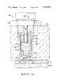
- FIG. 2is a footprint of the gas chromatography assembly of the present invention.
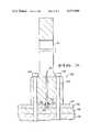
- FIG. 3is a cross-sectional view of the assembly of FIG. 2 taken along the line 3--3.
- FIG. 4is a partial cross-sectional view of a normally closed valve actuator used in the assembly of the present invention.
- FIG. 5is a partial cross-sectional view of a normally open valve actuator used in the assembly of the present invention.
- FIG. 6is a partial cross-sectional view of the injection pump used in the assembly of the present invention.
- FIG. 7is a partial cross-sectional side view of the modular capillary tube mounted on the assembly of the present invention.
- FIG. 1there is shown a schematic view of a miniature gas chromatography system, generally designated as 10.
- the system 10comprises a helium supply tank 12, which provides a carrier gas for the system 10.
- the carrier gasleaves the supply tank 12 and enters a line 14.
- the line 14has disposed therein a restrictor 16, which is used to reduce the flow volume of the carrier gas.
- the carrier gaspasses through the restrictor 16 to a first valve 18. From the first valve 18, the carrier gas is entered into a surge tank 20.
- the carrier gas, from the first valve 18,also enters into to a relief valve 22.
- the relief valve 22is used to relieve any pressure over that which is necessary for charging the surge tank 20.
- Carrier gas from the surge tank 20is entered into the carrier gas input 28 of the assembly 26 of the present invention.
- the assembly 26 of the present inventionis comprised of a substrate wafer 102, which has grooves etched therein.
- a typical material for the wafer 102is single crystalline silicon.
- a plate 104typically Pyrex glass, is attached to one side 103 of the wafer 102 and cooperates with the wafer 102 and the grooves therein to form gas channels.
- On the other side 105 of the plate 104is a support 106.
- the support 106is made of aluminum.
- the surge tank 20is in the aluminum support 106.
- a conduit 30passes through the plate 104, connecting the surge tank 20 to the carrier gas input 28. From the helium input 28, a first channel 29 is etched in the wafer 102 on the one side 103.
- the other end of the first channel 29is connected to a first pressure sensor 34, which is used to determine the proper operating pressure for the carrier gas within the assembly 26.
- the first pressure sensor 34is external to the assembly 26 and is mounted on the assembly 26.
- the first pressure sensor 34is mounted on the other side 107 of the wafer 102 and is connected to the first channel 29 by a feedthrough.
- a second channel 35 within the wafer 102connects the helium input 28 to a second valve seat 38. Within the second channel 35 is a second restrictor 36, the function of which will be described hereinafter.
- From the second valve seat 38one end of a third channel 40 is connected.
- the other end of the third channel 40is connected to an external column 42.
- From the external column 42a fourth channel 44 connects it to a detector 46.
- a fifth channel 48 in the assembly 26connects the detector 46 to a vent.
- a source 50provides the sample gas to be analyzed in the gas system 10.
- the sample gasenters the assembly 26 through a sixth channel 52 and into a third valve seat 54.
- a seventh channel 55connects the third valve seat 54 to the second valve seat 38.
- the sample gaspasses through an eighth channel 56 to a pump connection point 58.
- a high pressure pump 64is connected thereto.
- the high pressure pump 64has an inlet 66 and an outlet 68.
- the inlet 66 of the high pressure pump 64is connected at the pump connection point 58.
- the outlet 68 of the high pressure pump 64is connected to a diaphragm vacuum pump 70.
- the diaphragm vacuum pump 70draws the sample gas from the high pressure pump 64 and sends it out to vent.
- a ninth channel 60connects the pump connection point 58 to a second pressure sensor 62.
- the second and third valve seats 38 and 54are of the types shown and described in the report prepared under the National Institute for Occupational Safety and Health, as set forth in the Background of the Invention.
- a second and third valve actuating means 38a and 54a(shown in FIGS. 4 and 5, respectively) are mounted on the second and third valve seats 38 and 54, respectively.
- the first valve 18can also comprise a valve actuator operating on a valve seat, similar to the second valve actuator 38a on the second valve seat 38.
- the valve actuating means 38a and 54awill be described in greater detail hereinafter, and are attached to the substrate wafer 102 on the other side 107 thereof.
- the first pressure sensor 34is attached to the other side 107 of the substrate 102.
- Feedthroughs in the substrate wafer 102communicate each of the aforementioned external devices with the channels which are etched on the one side 103 of the wafer 102.
- the detector 46can be of the type described in the patent application Ser. No. 141,269, filed on Apr. 18, 1980, now abandoned.
- the first and second pressure sensors 34 and 62, respectively,can be of commercially available type of sensor, such as Kulite Semiconductor Inc. Model PTQH.
- the external column 42can also be of a commercially available type of column, such as the fused silica capillary column manufactured by Hewlett-Packard Corporation.
- the pump 64 used in the assembly 26will be described in detail hereinafter.
- the carrier gaswill flow from the tank 12 through the first valve 18 and into the surge tank 20. Once the surge tank 20 has been charged or pressurized, the first valve 18 is closed. Thereafter, the carrier gas will flow from the surge tank 20, through the conduit 30 into the second channel 35, through the restrictor 36 therein. The carrier gas then flows through the second valve seat 38, through the third channel 40 to the external column 42. The carrier gas will then re-enter the assembly 26 from the external column 42 and pass through the fourth channel 44 to a detector 46 and through a fifth channel 48 to vent. During normal operation, the sample gas will travel from the source 50, through a normally open third valve seat 54, through the second valve seat 38 into the inlet 66 of the pump 64.
- the sample gasis drawn through the outlet 68 of the pump 64 by the diaphragm vacuum pump 70 and to vent 72.
- the diaphragm vacuum pump 70draws the sample gas from the sample gas channel line (i.e. sixth, seventh and eighth channels 52, 55, and 56 respectively) out to vent.
- the vacuum action of the pump 70draws in new sample gas from the source 50 into the sample gas channel line.
- the third valve seat 54is closed by the third valve actuating means 54a, thereby shutting the flow of sample gas from the source 50.
- the pump 64is activated.
- the second valve actuating means 38awhich is seated on the second valve seat 38 is then operated to permit the sample gas from the eighth channel 56 to enter into the carrier gas line.
- the second valve seat 38is opened for a pre-determined amount of time (typically on the order of a few milliseconds).
- the sample gasenters through the second valve seat 38 and into the second and the third channels 35 and 40, respectively, of the carrier gas line.
- the second restrictor 36 in the second channel 35prevents the sample gas from flowing upstream into the surge tank 32 to contaminate it. Therefore, although some sample gas will enter into the second channel 35, substantially all of the sample gas from the eighth channel 56 will be injected into the third channel 40, into the external column 42 and will be measured by the detector 46.
- the volume of the eighth channel 56is chosen such that it acts as a buffer between the sample gas from the pump 64 and the second valve seat 38.
- the volume of the eighth channel 56is such that, upon activation of the pump 64, no sample gas which has been in the pump 64 reaches the second valve seat 38.
- the volume of the eighth channel 56must be greater than the compression ratio of the pump 64 times the volume of the gas which is in the second valve seat 38, seventh channel 55 and that portion of the third valve seat 54 which is in communication with the seventh channel 55 and is not closed by the third actuator 54a. In this manner, contamination of gas from the pump 64 into the carrier gas line is avoided.
- the pump 64stops its injection process and withdraws to its normal open position permitting gas flow from the inlet 66 to the outlet 68.
- Third valve seat 54is then opened permitting sample gas to flow from the source 50 to the pump 64, and out to vent by the diaphragm pump 70.
- the external column 42contains chemical means for the separation of the sample gas mixture into its constituent components.
- the external column 42may have to be different.
- the assembly 26 for the different applicationscan all be the same.
- the different external columns 42can be attached to the same assembly 26 for various applications. In this manner, only the external column 42 is different for different uses. Commonality of parts with decrease in inventory stock result in savings in manufacturing cost.
- FIG. 4there is shown a partial cross-sectional view of the second valve actuator 38a, used in the assembly 26 of the present invention.
- the valve actuator 38aconsists of a housing 200, with the housing 200 connected to the silicon wafer 102, plate 104 and support 106 by bolt 202. As shown in FIG. 2, there are three bolts 202 attaching the actuator 38a to the valve seat 38. Disposed above the housing 200 is an electrically operated solenoid 204, which is used to activate the valve 200 when desired. The solenoid 204 threadably engages the housing 200, and is locked into place by a nut 206.
- the housing 200has disposed therein a valve assembly 210.
- the valve assembly 210is bound securely in the housing 200 between the silicon wafer 102 and the solenoid 204.
- the assembly 210has disposed therein a sleeve 228 with an end 229.
- the sleeve 228has an orifice 226 in the end 229 thereof.
- a pin 224is within the orifice 226.
- a circular ring 225is at the outer surface of the end 229. The ring 225 engages the diaphragm 230 and when the solenoid 204 is threadably tightened, the ring 225 is pressed against the diaphragm 230 and the wafer 102 forming a tight seal.
- the sleeve 228also has disposed therein a first plunger 208.
- the first plunger 208slides through a first annular ring 212.
- the first annular ring 212is clamped between the solenoid 204 and the sleeve 228.
- the first plunger 208is mounted in the solenoid 204, such that upon activation of the solenoid 204, the first plunger 208 is moved in the direction shown by the arrow A.
- a body 214At the end of the first plunger 208 which is within the sleeve 228 is a body 214.
- a first spring 216is between the body 214 and the first annular ring 212. The first spring 216 urges the body 214 away from the solenoid 204.
- a second plunger 218Within the body 214 is a second plunger 218.
- the body 214has a lip 220 therein which captures the second plunger 218.
- a second spring 222is also within the body 214. The second spring 222 urges one end of the second plunger away from the first plunger 208.
- the plunger 218is in free contact with the pin 224.
- the pin 224is aligned to impinge the diaphragm 230.
- the diaphragm 230controls the flow of gas through the valve seat 38.
- the pin 224is aligned to move in a direction substantially perpendicular to the plane of the diaphragm 230.
- the first spring 216urges the body 214 away from the solenoid 204 until the shoulder on the plunger 208 stops against the ring 212.
- the second spring 222urges the second plunger 218 away from the first plunger 208.
- the action of the second spring 222 against the second plunger 218causes the second plunger 218 to impinge the pin 224, pushing it against the diaphragm 230, closing off the gas flowing to the valve seat 38.
- the first plunger 208When the solenoid 204 is activated, the first plunger 208 is pulled in a direction shown substantially by the arrow A.
- the first plunger 208pulls the body 214 with it in the direction as shown by the arrow A.
- the lip 220 of the body 214pulls the second plunger 218 also in the direction shown by the arrow A.
- the effect of solenoid 204 pulling on the first plunger 208is then to compress the first spring 216.
- the pin 224however, is only in free contact with the second plunger 218.
- the pin 224moves in the direction shown by the arrow A only due to the springlike resilient restoring force of the diaphragm 230 and by the force of the gas pushing against the diaphragm 230.
- the spring action of the first spring 216pushes the body 214 away from the solenoid 204.
- the plunger 218stops its movement in the direction opposite to that shown by arrow A and disengages from the lip 220 of the body 214.
- Spring 222is compressed by the further movement of plunger 218 in the direction opposite shown by arrow A.
- the force of the second spring 222, pushing against the second plunger 218,also pushes the pin 224 against the diaphragm 230 to close off the valve seat 38.
- valve seat 38is normally closed to the flow of gas.
- the pin 224 which impacts the diaphragm 230 to open or close the valve 38is moved by the valve assembly 210 only in the direction opposite to that shown by the arrow A.
- the solenoid 204is activated, moving the valve assembly 210 away from the pin 224, the pin 224 is moved in the direction opposite to that shown by the arrow A only by the diaphragm 230 and the force of gas flowing through the valve seat 38.
- the function of the valve assembly 210is to act as a force-transmitting means, such that during the closing of the valve seat 38, a gentle and gradual force is applied on the pin 224.
- the force which is applied against the pin 224 to close off the valve seat 38is applied by the force of the second spring 222.
- the second spring 222can be made to apply a very gentle and gradual force, such as on the order of 50 grams of force. Gradual and gentle forces are needed because sudden forces applied against the pin 224 can cause breakage of the pin 224 and/or greatly deteriorate the life of the diaphragm 230 when the diaphragm is repeatedly and suddenly struck by the pin 224 and impinged against the wafer 102.
- the orifice 226 in which the free pin 224 is situatedis part of the housing 200, and the housing 200 is aligned substantially perpendicular to the diaphragm 230, and the wafer 102, the pin 224 would also be aligned substantially perpendicular to the diaphragm 230 and the wafer 102. This provides greater accuracy in the operation of the valve 38a.
- FIG. 5there is shown a partial cross-sectional view of the third valve actuator 54a used in the assembly 26 of the present invention.
- the valve actuator 54aconsists of a housing 250, with the housing 250 connected to the silicon wafer 102, the plate 104 and the support 106 by bolts 252. Again, as shown in FIG. 2, there are three bolts 252 attaching the valve actuator 54a to the assembly 26. Disposed above the housing 250 is an electrically operated solenoid 254 which is used to activate the valve 54a when desired. The solenoid 254 threadably engages housing 250 and is locked into place by a nut 256.
- the housing 250has disposed therein a valve assembly 260.
- the valve assembly 260is bound securely in the housing 250 between the silicon wafer 102 and the solenoid 254.
- the assembly 260has disposed therein a sleeve 262.
- This sleeve 262is similar to the sleeve 228 described for the second valve actuator 38a, as shown in FIG. 4.
- the sleeve 262has an orifice 264 at one end 265 thereof.
- a free pin 266is disposed within the orifice 264.
- the housing 250is attached to the wafer 102, plate 104, and support 106, such that the orifice 264 and, therefore, the pin 266 is in substantially perpendicular alignment with the diaphragm 280 of the valve seat 54.
- the sleeve 262also has a circular ring 263 which engages the diaphragm 280. When the bolts 252 are tightened, the circular ring 263 is pressed against the diaphragm 280 and against the wafer 102 forming a tight seal for the valve seat 54.
- first plunger 268Within the valve assembly 260 is a first plunger 268.
- the first plunger 268extends through the valve assembly 260 into the solenoid 254.
- the first plunger 268Upon activation of the solenoid 254, the first plunger 268 is moved in the direction shown by the arrow "B".
- a first ring 270is attached around the first plunger 268 near the solenoid 254.
- a second ring 274is attached around the plunger 268 by E-ring 269 near the end of the plunger 268, away from the solenoid 254.
- a first spring 272is disposed between the first ring 270 and the second ring 274 and is always in compression.
- the second ring 274is in contact with one end of a cylindrical body 276.
- the other end of the cyclindrical body 276is in free contact with the pin 266.
- a second spring 278is disposed around the other end of the cyclindrical body 276 and urges the body 276 away from the one end 265 of the sleeve 262. The action of the second spring 278 is to urge the body 276 against the second ring 274. The body 276 is urged against the second ring 274 until the second ring 274 comes to a rest against the stop 282.
- the plunger 268In the operation of the actuator 54a, when the solenoid 254 is activated, the plunger 268 is moved in the direction shown by the arrow B. The movement of the plunger 268 pushes the first ring 270 thereby compressing the spring 272. The spring 272 then pushes against the second ring 274. The force of the first spring 272 is then transmitted to the cylindrical body 276. This force, i.e., the force of the first spring 272, then works against the force of compression of the second spring 278. Therefore, the amount of force acting on cylindrical body 276 is the difference in force between the first spring 272 and the second spring 278. This force acting on the body 276 is then transmitted to the pin 266. The pin 266 impinges against the diaphragm 280 closing off the flow of gas through the valve seat 54.
- the force of the second spring 278would urge the cylindrical body 276 upward, i.e., in the direction opposite to that shown by the arrow B.
- the body 276would then urge against the second ring 274 pushing the plunger 268 back into the state shown in FIG. 5.
- the pin 266is in free contact with the one end of the body 276.
- the pinis retracted and is moved in a direction opposite to that shown by the arrow B by the springlike force of the diaphragm 280, returning to its normal position. Therefore, the pin 266 is affected by the force of activation of the valve actuator 54a in only the direction shown by the arrow "B".
- the restoration of the pin 266 to its normal stateis not directly caused by the de-energization of the solenoid 254.
- the function of the valve assembly 260is to act as a force transmitting means such that during the activation of the solenoid 254, a more gentle and gradual force is applied on the pin 266, and consequently against the diaphragm 280.
- the amount of force applied against the pin 266is the difference in the spring compression between the first spring 272 and the second spring 278. This difference can be adjusted such that the amount of force applied against the pin 266 can be extremely gradual and gentle.
- the orifice 264 in which the pin 266 is situatedis part of the housing 250, the housing 250 can be aligned substantially perpendicular to the diaphragm 280 and the wafer 102 providing accuracy in the operation of the valve 54a.
- FIG. 6shows a partial, cross-sectional view of a high-pressure injection pump 64 used in the assembly 26 of the present invention.
- the pump 64has a housing 402.
- the housing 402is attached to the wafer 102, the plate 104, and the aluminum support 106 by a bolt 404. As shown in FIG. 2, there are three bolts 404 attaching the pump 64 to the assembly 26.
- the housing 402has an orifice 403 for connection to a diaphragm vacuum pump 70. Threadably connected to the housing 402 is a solenoid 406.
- the solenoid 406has an operable member 424 which is used to actuate the pump 64.
- Inside the housing 402is a glass tube 411.
- a piston 408is disposed within the glass tube 411.
- the piston 408is prevented from any upward movement past the glass tube 411 by spring stops 410.
- Piston 408has an annular groove 409 which is aligned with orifice 403 of housing 402 to allow sample gas flow to the diaphragm vacuum pump 70 during normal operations, when sample gas is not being injected into the external column 42.
- the piston 408also has seals 416 to prevent flow of gas between the piston 408 and the glass tube 411.
- the piston 408has a base 418, which has an aperture 420 therein.
- the piston 408also has a bore, which has affixed therein a valve guide 430.
- the valve guide 430is threaded on to the piston 408 and extends upward between the base 418 of the piston 408 up to the solenoid operable member 424.
- the upper portion of the valve guide 430has an annular groove which has therein disposed a spring retainer 432.
- the spring retainer 432impinges upon the nylon shoulder washer 412 which, with spring stop 410, provide spring retainer means for the spring 414.
- valve plunger 434Within the valve guide 430 is a valve plunger 434.
- the valve plunger 434extends from the operable portion 424 of the solenoid 406 down to the base 418. Near the base of the valve plunger 434 is an annular groove 442 which has disposed thereon sealing O-ring 436.
- the O-ring 436prevents the flow of gas past the O-ring 436 such that gas will not enter between the valve guide 430 and valve plunger 434.
- the end of the valve plunger 434has an end 440. Disposed about the end 440 is a second O-ring 438.
- the end 440 and the second O-ring 438can be sealably engaged with the orifice 420.
- At the other end of the plunger 434is a bore which has disposed therein second spring 428.
- the second spring 428is retained in its position by the annular ledge of the bore and by an E-ring 426.
- the valve guide 430 near the base 418 of the piston 408has a portion cut-out such that the gas flow through the aperture 420 past the base portion of the valve plunger 434, and through the annular groove 409 of the piston 408 and out the orifice 403 of the housing 402.
- the solenoid 406When the pump 400 is in operation, the solenoid 406 is activated and the operable member 424 will move in a direction "C" which will move the plunger 434 down a discrete amount until the second O-ring 438 engages and then seals the orifice 420. At this point, the gas from the wafer 102 is sealed off from communication with the orifice 403 of the housing 402. As the operable member 424 proceeds further in the direction shown by the arrow C, and since the valve plunger 434 is against the base 418 of the piston 408, the downward movement of the entire valve guide 430 will cause the piston 408 to move in the direction shown by the arrow C. The piston 408 then separates from the spring stop 410. Additionally, the springs 414 will be compressed during this downward motion. The movement of the entire piston assembly 408 causes the gas in the chamber 460 to be compressed and to be injected into the wafer 102.
- the compression of the gas within the chamber 460will cause the pressure of the gas to increase. Seals 416 and O-rings 438 and 422 prevent the gas within the chamber 460 from communicating with the outside atmosphere.
- the downward action of the piston 408continues until the pressure of the gas in the chamber 460 and in channel 56 is higher than the pressure of the carrier gas in channels 35 and 40 in the wafer 102. With the second valve 38 opened, this permits the injection of the sample gas into the carrier gas line.
- the solenoid 406will push the piston 408 in the direction shown by the arrow C until the solenoid 406 reaches its limit.
- the piston 408then stops.
- the amount of travel of the piston 408can be adjusted by the amount of threading of the solenoid 406 to the housing 402. This in turn adjusts the compression ratio of the pump 64.
- the solenoid 406is de-energized.
- Spring 414will then push the piston 408 back up against spring stop 410.
- the spring 414will also position the nylon shoulder washer 412 to the position shown in FIG. 6.
- spring 428will bias against the annular bore within the valve guide 430 and bias the operable portion 424 back to its original position, lifting the end of the valve plunger 434 from the base 418 of the piston 408. This opens up the aperture 420.
- O-ring 436forms a seal between the plunger 434 and the bore 430.
- FIG. 7there is shown a partial cross-sectional side view of a coupling device 500 for attaching the external column 42 to the silicon wafer 102, glass plate 104, and the support 106.
- the coupling device 500has a housing 502 and is connected to the wafer 102, plate 104 and support 106 by bolts 504. There are four bolts 504 attaching the external column 42 to the assembly 26.
- the housing 502has a sleeve 508 which is inserted into a feedthrough 522 in the wafer 102.
- the sleeve 508has an end 524 which extends into the feedthrough 522.
- An O-ring 520is disposed in an annular groove around the sleeve 508.
- the O-ring 520is in contact with the other side 107 of the wafer 102. Although the end 524 extends into the wafer 102, there is not enough volume in the feedthrough 522 in which it extends such that it will create a dead volume problem of gas remaining in the feedthrough 522.
- the external column 42has a coupling end 506, which fits within the sleeve 508. A sealing material, such as epoxy glue, seals the end 506 within the sleeve 508.
- the bolts 504assertably engages the external column 42 with the housing 502, and extends the sleeve 508 into the feedthrough 522 of the wafer 102.
- the O-ring 520forms a tight seal.
Landscapes
- Chemical & Material Sciences (AREA)
- Analytical Chemistry (AREA)
- Physics & Mathematics (AREA)
- Health & Medical Sciences (AREA)
- Life Sciences & Earth Sciences (AREA)
- Biochemistry (AREA)
- General Health & Medical Sciences (AREA)
- General Physics & Mathematics (AREA)
- Immunology (AREA)
- Pathology (AREA)
- Nanotechnology (AREA)
- Engineering & Computer Science (AREA)
- Sampling And Sample Adjustment (AREA)
Abstract
Description
Claims (24)
Priority Applications (3)
| Application Number | Priority Date | Filing Date | Title |
|---|---|---|---|
| US06/371,617US4474889A (en) | 1982-04-26 | 1982-04-26 | Miniature gas chromatograph apparatus |
| DE8383103821TDE3369886D1 (en) | 1982-04-26 | 1983-04-20 | Miniature gas chromatograph apparatus |
| EP83103821AEP0092779B1 (en) | 1982-04-26 | 1983-04-20 | Miniature gas chromatograph apparatus |
Applications Claiming Priority (1)
| Application Number | Priority Date | Filing Date | Title |
|---|---|---|---|
| US06/371,617US4474889A (en) | 1982-04-26 | 1982-04-26 | Miniature gas chromatograph apparatus |
Publications (1)
| Publication Number | Publication Date |
|---|---|
| US4474889Atrue US4474889A (en) | 1984-10-02 |
Family
ID=23464691
Family Applications (1)
| Application Number | Title | Priority Date | Filing Date |
|---|---|---|---|
| US06/371,617Expired - LifetimeUS4474889A (en) | 1982-04-26 | 1982-04-26 | Miniature gas chromatograph apparatus |
Country Status (1)
| Country | Link |
|---|---|
| US (1) | US4474889A (en) |
Cited By (53)
| Publication number | Priority date | Publication date | Assignee | Title |
|---|---|---|---|---|
| US4891120A (en)* | 1986-06-06 | 1990-01-02 | Sethi Rajinder S | Chromatographic separation device |
| US4905497A (en)* | 1987-06-05 | 1990-03-06 | Hitachi, Ltd. | Gas mixing device and gas analyzer making use of the same |
| US4909078A (en)* | 1987-10-14 | 1990-03-20 | Rosemount Inc. | Fluid flow detector |
| US5058856A (en)* | 1991-05-08 | 1991-10-22 | Hewlett-Packard Company | Thermally-actuated microminiature valve |
| US5126022A (en)* | 1990-02-28 | 1992-06-30 | Soane Tecnologies, Inc. | Method and device for moving molecules by the application of a plurality of electrical fields |
| USH1190H (en) | 1991-06-21 | 1993-06-01 | Analytical sampling valve | |
| US5340543A (en)* | 1990-08-22 | 1994-08-23 | The Foxboro Company | Modular gas chromatography device |
| US5355718A (en)* | 1992-12-09 | 1994-10-18 | International Flavors & Fragrances Inc. | Aroma emission analysis system |
| US5363707A (en)* | 1992-05-01 | 1994-11-15 | Hewlett-Packard Company | Headspace sampling system |
| WO1995015485A1 (en)* | 1993-11-30 | 1995-06-08 | Microsensor Technology, Inc. | Fluid-lock fixed volume injector |
| US5544276A (en)* | 1993-11-30 | 1996-08-06 | Microsensors Technology, Inc. | Miniature gas chromatograph with heated gas inlet fitting, heated tubing, and heated microvalve assembly |
| WO1996027792A1 (en)* | 1995-03-03 | 1996-09-12 | Microsensor Technology, Inc. | Fixed-volumed injector with backflush capability |
| US5567868A (en)* | 1995-01-23 | 1996-10-22 | Hewlett-Packard Company | Planar manifold assembly |
| US5581028A (en)* | 1994-06-23 | 1996-12-03 | Hewlett Packard Company | Fluid property sensors incorporating plated metal rings for improved packaging |
| US5645702A (en)* | 1995-06-07 | 1997-07-08 | Hewlett-Packard Company | Low voltage miniaturized column analytical apparatus and method |
| US5663488A (en)* | 1995-05-31 | 1997-09-02 | Hewlett-Packard Co. | Thermal isolation system in an analytical instrument |
| WO1997047013A1 (en)* | 1996-06-07 | 1997-12-11 | Marotta Scientific Controls, Inc. | Micro gas rheostat |
| US5720798A (en)* | 1996-04-30 | 1998-02-24 | Hewlett-Packard Company | Micromachined analyte trap for gas phase streams |
| US5750015A (en)* | 1990-02-28 | 1998-05-12 | Soane Biosciences | Method and device for moving molecules by the application of a plurality of electrical fields |
| US5780748A (en)* | 1997-01-29 | 1998-07-14 | Hewlett-Packard Company | Flow device having parallel flow surfaces which move toward and away from one another to adjust the flow channel in proportion to applied force |
| US5792943A (en)* | 1997-04-30 | 1998-08-11 | Hewlett-Packard Company | Planar separation column for use in sample analysis system |
| US5804701A (en)* | 1996-10-22 | 1998-09-08 | Hewlett-Packard Company | Compact, low-profile chromatograph |
| US5856616A (en)* | 1997-03-21 | 1999-01-05 | The United States Of America As Represented By The Secretary Of The Army | Hand-held temperature programmable modular gas chromatograph |
| US5888390A (en)* | 1997-04-30 | 1999-03-30 | Hewlett-Packard Company | Multilayer integrated assembly for effecting fluid handling functions |
| US5935430A (en)* | 1997-04-30 | 1999-08-10 | Hewlett-Packard Company | Structure for capturing express transient liquid phase during diffusion bonding of planar devices |
| US5997708A (en)* | 1997-04-30 | 1999-12-07 | Hewlett-Packard Company | Multilayer integrated assembly having specialized intermediary substrate |
| US6004514A (en)* | 1991-02-15 | 1999-12-21 | Yamatake Corporation | Process gas chromatographic system |
| US6056269A (en)* | 1999-01-15 | 2000-05-02 | Hewlett-Packard Company | Microminiature valve having silicon diaphragm |
| US6068010A (en)* | 1995-06-09 | 2000-05-30 | Marotta Scientific Controls, Inc. | Microvalve and microthruster for satellites and methods of making and using the same |
| US6102449A (en)* | 1998-10-29 | 2000-08-15 | Agilent Technologies, In. | Connector for capillary tubing |
| US6141497A (en)* | 1995-06-09 | 2000-10-31 | Marotta Scientific Controls, Inc. | Multilayer micro-gas rheostat with electrical-heater control of gas flow |
| US6158712A (en)* | 1998-10-16 | 2000-12-12 | Agilent Technologies, Inc. | Multilayer integrated assembly having an integral microminiature valve |
| US6217829B1 (en)* | 1997-01-27 | 2001-04-17 | Rvm Scientific, Inc. | Reduced power consumption gas chromatograph system |
| WO2001073424A1 (en)* | 2000-03-27 | 2001-10-04 | Halliburton Energy Services, Inc. | Method and apparatus for the down-hole characterization of formation fluids |
| US6527890B1 (en) | 1998-10-09 | 2003-03-04 | Motorola, Inc. | Multilayered ceramic micro-gas chromatograph and method for making the same |
| US6568244B2 (en)* | 2000-03-20 | 2003-05-27 | Abb Research Ltd. | Measuring and evaluating device |
| US6575014B2 (en)* | 2001-06-01 | 2003-06-10 | Agilent Technologies, Inc. | Silicon micro-machined fixed-volume back-flush injector having no unswept dead volume during injection |
| US6698798B2 (en)* | 2000-04-13 | 2004-03-02 | California Institute Of Technology | Micromachined rubber O-ring microfluidic couplers |
| DE10301601B3 (en)* | 2003-01-16 | 2004-08-12 | Sls Micro Technology Gmbh | Miniaturized gas chromatograph and injector therefor |
| US6808609B1 (en) | 1990-02-28 | 2004-10-26 | Aclara Biosciences, Inc. | Device and method for moving charged particles |
| US20040255643A1 (en)* | 2003-05-13 | 2004-12-23 | Wise Kensall D. | High-performance separation microcolumn assembly and method of making same |
| US20050109079A1 (en)* | 2003-11-21 | 2005-05-26 | Shimadzu Corporation | Gas chromatograph set |
| US20070266857A1 (en)* | 2006-05-16 | 2007-11-22 | James Bentley | Gas chromatograph column assembly |
| US20070266858A1 (en)* | 2006-05-16 | 2007-11-22 | Sheena Alm | Multi-dimensional portable gas chromatograph system |
| US20070266856A1 (en)* | 2006-05-16 | 2007-11-22 | John Blankevoort | Very small high pressure regulator |
| US7485176B2 (en) | 2006-05-16 | 2009-02-03 | Alliant Techsystems Inc. | Compact thermal conductivity detector |
| US20100059699A1 (en)* | 2008-09-08 | 2010-03-11 | Mecanique Analytique Inc. | Temperature compensated valve for gas chromatography |
| US20100117308A1 (en)* | 2008-11-10 | 2010-05-13 | Eaton Corporation | Pressure sensing module having an integrated seal plate and method of assembling pressure sensing module |
| US20120025120A1 (en)* | 2009-04-01 | 2012-02-02 | Yves Gamache | Self-aligned plunger for chromatographic valve |
| US8994556B2 (en) | 2012-05-24 | 2015-03-31 | Douglas H. Lundy | Threat detection system and method |
| US20150137015A1 (en)* | 2012-07-12 | 2015-05-21 | Agency For Science, Technology And Research | Connector for microfluidic device, a method for injecting fluid into microfluidic device using the connector and a method of providing and operating a valve |
| US9389208B2 (en) | 2013-01-25 | 2016-07-12 | Rosemount Analytical Inc. | Hermetic manifold for analytical instruments |
| FR3100337A1 (en)* | 2019-09-04 | 2021-03-05 | L'air Liquide, Societe Anonyme Pour L'etude Et L'exploitation Des Procedes Georges Claude | New method of calibrating a gas chromatograph |
Citations (10)
| Publication number | Priority date | Publication date | Assignee | Title |
|---|---|---|---|---|
| US3138025A (en)* | 1960-07-18 | 1964-06-23 | Leroy M Fingerson | High temperature probe |
| US3138948A (en)* | 1960-09-13 | 1964-06-30 | Engelhard Ind Inc | Hydrogen measuring system |
| US3333470A (en)* | 1964-06-01 | 1967-08-01 | Thermo Systems Inc | Method and apparatus for sensing fluid properties |
| US3538744A (en)* | 1967-11-09 | 1970-11-10 | Phillips Petroleum Co | Chromatography apparatus |
| US3633426A (en)* | 1970-08-10 | 1972-01-11 | Phillips Petroleum Co | Chromatographic analyzer sample valve |
| US3911386A (en)* | 1975-01-15 | 1975-10-07 | Ford Motor Co | Exhaust gas air fuel ratio sensor |
| US4033169A (en)* | 1974-08-09 | 1977-07-05 | Nissan Motor Co., Ltd. | Hydrocarbon concentration sensor for use in engine exhaust gas |
| US4142400A (en)* | 1977-03-07 | 1979-03-06 | Johnson Controls, Inc. | Nitrogen dioxide sensing element and method of sensing the presence of nitrogen dioxide |
| US4241019A (en)* | 1978-02-20 | 1980-12-23 | Matsushita Electric Industrial Co., Ltd. | Combustible gas detecting element |
| US4359891A (en)* | 1981-01-05 | 1982-11-23 | The Dow Chemical Company | Repetitive chromatographic apparatus |
- 1982
- 1982-04-26USUS06/371,617patent/US4474889A/ennot_activeExpired - Lifetime
Patent Citations (10)
| Publication number | Priority date | Publication date | Assignee | Title |
|---|---|---|---|---|
| US3138025A (en)* | 1960-07-18 | 1964-06-23 | Leroy M Fingerson | High temperature probe |
| US3138948A (en)* | 1960-09-13 | 1964-06-30 | Engelhard Ind Inc | Hydrogen measuring system |
| US3333470A (en)* | 1964-06-01 | 1967-08-01 | Thermo Systems Inc | Method and apparatus for sensing fluid properties |
| US3538744A (en)* | 1967-11-09 | 1970-11-10 | Phillips Petroleum Co | Chromatography apparatus |
| US3633426A (en)* | 1970-08-10 | 1972-01-11 | Phillips Petroleum Co | Chromatographic analyzer sample valve |
| US4033169A (en)* | 1974-08-09 | 1977-07-05 | Nissan Motor Co., Ltd. | Hydrocarbon concentration sensor for use in engine exhaust gas |
| US3911386A (en)* | 1975-01-15 | 1975-10-07 | Ford Motor Co | Exhaust gas air fuel ratio sensor |
| US4142400A (en)* | 1977-03-07 | 1979-03-06 | Johnson Controls, Inc. | Nitrogen dioxide sensing element and method of sensing the presence of nitrogen dioxide |
| US4241019A (en)* | 1978-02-20 | 1980-12-23 | Matsushita Electric Industrial Co., Ltd. | Combustible gas detecting element |
| US4359891A (en)* | 1981-01-05 | 1982-11-23 | The Dow Chemical Company | Repetitive chromatographic apparatus |
Non-Patent Citations (19)
| Title |
|---|
| "A Feasibility Study of a Pocket-Sized Gas Chromatographic Air Analyzer" by Stephen C. Terry & John H. Jerman; Jul. 1977. |
| "A New Detector for Gaseous Components Using Semiconductive Thin Films", Analytical Chemistry, vol. 34, No. 11, Oct. 1962. |
| "A Prototype Gas Analysis System Using a Miniature Gas Chromatograph" by James B. Angell, et al., Apr. 1981. |
| "A Prototype Gas Analysis System Using a Miniature Gas Chromatograph" by John H. Jerman, et al., Jun. 1, 1980. |
| "Developments in Micro Gas Chromatography" by W. F. Wilhite, J. of G.C.-Feb. 1966, p. 47. |
| "Study on a Detector for Gaseous Components Using Semiconductive Thin Films", vol. 38, No. 8, Jul. 1966. |
| "Vacuum Ultraviolet Photochemistry in Thin Resist Films" by Paul W. Bohn & James W. Taylor, Analytical Chemistry, vol. 53, No. 7, Jun. 1981, pp. 1082-1087. |
| A Feasibility Study of a Pocket Sized Gas Chromatographic Air Analyzer by Stephen C. Terry & John H. Jerman; Jul. 1977.* |
| A New Detector for Gaseous Components Using Semiconductive Thin Films , Analytical Chemistry, vol. 34, No. 11, Oct. 1962.* |
| A Prototype Gas Analysis System Using a Miniature Gas Chromatograph by James B. Angell, et al., Apr. 1981.* |
| A Prototype Gas Analysis System Using a Miniature Gas Chromatograph by John H. Jerman, et al., Jun. 1, 1980.* |
| Chemical Abstracts, 90: 97088d (1979).* |
| Developments in Micro Gas Chromatography by W. F. Wilhite, J. of G.C. Feb. 1966, p. 47.* |
| S. C. Terry et al., Theory, Des., Biomed. Appl. Solid State Chem. Sens., Workshop 1977 (Pub. 1978), 207 218 (Eng), edited by Cheung, Peter W.; Fleming, David G.; Neuman, Michael R., CRC: West Palm Beach, Fla.* |
| S. C. Terry et al., Theory, Des., Biomed. Appl. Solid State Chem. Sens., Workshop 1977 (Pub. 1978), 207-218 (Eng), edited by Cheung, Peter W.; Fleming, David G.; Neuman, Michael R., CRC: West Palm Beach, Fla. |
| Study on a Detector for Gaseous Components Using Semiconductive Thin Films , vol. 38, No. 8, Jul. 1966.* |
| Terry, Steven C. et al., IEEE Trans. Electron Devices, vol. Ed. 26, No. 12, 1880 1886 (Dec. 1979).* |
| Terry, Steven C. et al., IEEE Trans. Electron Devices, vol. Ed.-26, No. 12, 1880-1886 (Dec. 1979). |
| Vacuum Ultraviolet Photochemistry in Thin Resist Films by Paul W. Bohn & James W. Taylor, Analytical Chemistry, vol. 53, No. 7, Jun. 1981, pp. 1082 1087.* |
Cited By (74)
| Publication number | Priority date | Publication date | Assignee | Title |
|---|---|---|---|---|
| US4891120A (en)* | 1986-06-06 | 1990-01-02 | Sethi Rajinder S | Chromatographic separation device |
| US4905497A (en)* | 1987-06-05 | 1990-03-06 | Hitachi, Ltd. | Gas mixing device and gas analyzer making use of the same |
| US4977776A (en)* | 1987-06-05 | 1990-12-18 | Hitachi, Ltd. | Gas mixing device and gas analyzer making use of the same |
| US4909078A (en)* | 1987-10-14 | 1990-03-20 | Rosemount Inc. | Fluid flow detector |
| US5750015A (en)* | 1990-02-28 | 1998-05-12 | Soane Biosciences | Method and device for moving molecules by the application of a plurality of electrical fields |
| US5126022A (en)* | 1990-02-28 | 1992-06-30 | Soane Tecnologies, Inc. | Method and device for moving molecules by the application of a plurality of electrical fields |
| US6306272B1 (en) | 1990-02-28 | 2001-10-23 | Soane Biosciences, Inc. | Method and device for performing chemical reactions |
| US6808609B1 (en) | 1990-02-28 | 2004-10-26 | Aclara Biosciences, Inc. | Device and method for moving charged particles |
| US6964735B2 (en) | 1990-02-28 | 2005-11-15 | Aclara Biosciences, Inc. | Method for moving charged particles |
| US5340543A (en)* | 1990-08-22 | 1994-08-23 | The Foxboro Company | Modular gas chromatography device |
| US6004514A (en)* | 1991-02-15 | 1999-12-21 | Yamatake Corporation | Process gas chromatographic system |
| US5058856A (en)* | 1991-05-08 | 1991-10-22 | Hewlett-Packard Company | Thermally-actuated microminiature valve |
| USH1190H (en) | 1991-06-21 | 1993-06-01 | Analytical sampling valve | |
| US5363707A (en)* | 1992-05-01 | 1994-11-15 | Hewlett-Packard Company | Headspace sampling system |
| US5355718A (en)* | 1992-12-09 | 1994-10-18 | International Flavors & Fragrances Inc. | Aroma emission analysis system |
| US5487313A (en)* | 1993-11-30 | 1996-01-30 | Microsensor Technology, Inc. | Fluid-lock fixed-volume injector |
| US5544276A (en)* | 1993-11-30 | 1996-08-06 | Microsensors Technology, Inc. | Miniature gas chromatograph with heated gas inlet fitting, heated tubing, and heated microvalve assembly |
| WO1995015485A1 (en)* | 1993-11-30 | 1995-06-08 | Microsensor Technology, Inc. | Fluid-lock fixed volume injector |
| US5581028A (en)* | 1994-06-23 | 1996-12-03 | Hewlett Packard Company | Fluid property sensors incorporating plated metal rings for improved packaging |
| US5567868A (en)* | 1995-01-23 | 1996-10-22 | Hewlett-Packard Company | Planar manifold assembly |
| US5652398A (en)* | 1995-03-03 | 1997-07-29 | Microsensor Technology, Inc. | Fixed-volume injector with backflush capability |
| WO1996027792A1 (en)* | 1995-03-03 | 1996-09-12 | Microsensor Technology, Inc. | Fixed-volumed injector with backflush capability |
| US5663488A (en)* | 1995-05-31 | 1997-09-02 | Hewlett-Packard Co. | Thermal isolation system in an analytical instrument |
| US5645702A (en)* | 1995-06-07 | 1997-07-08 | Hewlett-Packard Company | Low voltage miniaturized column analytical apparatus and method |
| US6068010A (en)* | 1995-06-09 | 2000-05-30 | Marotta Scientific Controls, Inc. | Microvalve and microthruster for satellites and methods of making and using the same |
| US6141497A (en)* | 1995-06-09 | 2000-10-31 | Marotta Scientific Controls, Inc. | Multilayer micro-gas rheostat with electrical-heater control of gas flow |
| US5720798A (en)* | 1996-04-30 | 1998-02-24 | Hewlett-Packard Company | Micromachined analyte trap for gas phase streams |
| WO1997047013A1 (en)* | 1996-06-07 | 1997-12-11 | Marotta Scientific Controls, Inc. | Micro gas rheostat |
| DE19730761C2 (en)* | 1996-10-22 | 2003-04-10 | Agilent Technologies Inc | Compact chromatograph with a small cross-section |
| US5804701A (en)* | 1996-10-22 | 1998-09-08 | Hewlett-Packard Company | Compact, low-profile chromatograph |
| US6217829B1 (en)* | 1997-01-27 | 2001-04-17 | Rvm Scientific, Inc. | Reduced power consumption gas chromatograph system |
| US6682699B2 (en) | 1997-01-27 | 2004-01-27 | Rvm Scientific, Inc. | Reduced power consumption gas chromatograph system |
| US5780748A (en)* | 1997-01-29 | 1998-07-14 | Hewlett-Packard Company | Flow device having parallel flow surfaces which move toward and away from one another to adjust the flow channel in proportion to applied force |
| US5856616A (en)* | 1997-03-21 | 1999-01-05 | The United States Of America As Represented By The Secretary Of The Army | Hand-held temperature programmable modular gas chromatograph |
| US5935430A (en)* | 1997-04-30 | 1999-08-10 | Hewlett-Packard Company | Structure for capturing express transient liquid phase during diffusion bonding of planar devices |
| US5888390A (en)* | 1997-04-30 | 1999-03-30 | Hewlett-Packard Company | Multilayer integrated assembly for effecting fluid handling functions |
| US5997708A (en)* | 1997-04-30 | 1999-12-07 | Hewlett-Packard Company | Multilayer integrated assembly having specialized intermediary substrate |
| US5792943A (en)* | 1997-04-30 | 1998-08-11 | Hewlett-Packard Company | Planar separation column for use in sample analysis system |
| US6527890B1 (en) | 1998-10-09 | 2003-03-04 | Motorola, Inc. | Multilayered ceramic micro-gas chromatograph and method for making the same |
| US6732567B2 (en) | 1998-10-09 | 2004-05-11 | Motorola, Inc. | Multilayered ceramic micro-gas chromatograph and method for making the same |
| US6158712A (en)* | 1998-10-16 | 2000-12-12 | Agilent Technologies, Inc. | Multilayer integrated assembly having an integral microminiature valve |
| US6102449A (en)* | 1998-10-29 | 2000-08-15 | Agilent Technologies, In. | Connector for capillary tubing |
| US6056269A (en)* | 1999-01-15 | 2000-05-02 | Hewlett-Packard Company | Microminiature valve having silicon diaphragm |
| US6568244B2 (en)* | 2000-03-20 | 2003-05-27 | Abb Research Ltd. | Measuring and evaluating device |
| WO2001073424A1 (en)* | 2000-03-27 | 2001-10-04 | Halliburton Energy Services, Inc. | Method and apparatus for the down-hole characterization of formation fluids |
| US6698798B2 (en)* | 2000-04-13 | 2004-03-02 | California Institute Of Technology | Micromachined rubber O-ring microfluidic couplers |
| US6575014B2 (en)* | 2001-06-01 | 2003-06-10 | Agilent Technologies, Inc. | Silicon micro-machined fixed-volume back-flush injector having no unswept dead volume during injection |
| US20060210441A1 (en)* | 2003-01-16 | 2006-09-21 | Tobias Schmidt | Miniaturized gas chromatograph and injector for the same |
| US7959865B2 (en) | 2003-01-16 | 2011-06-14 | Sls Micro Technology Gmbh | Miniaturized gas chromatograph and injector for the same |
| DE10301601B3 (en)* | 2003-01-16 | 2004-08-12 | Sls Micro Technology Gmbh | Miniaturized gas chromatograph and injector therefor |
| US20040255643A1 (en)* | 2003-05-13 | 2004-12-23 | Wise Kensall D. | High-performance separation microcolumn assembly and method of making same |
| US7137286B2 (en)* | 2003-11-21 | 2006-11-21 | Shimadzu Corporation | Gas chromatograph set |
| US20050109079A1 (en)* | 2003-11-21 | 2005-05-26 | Shimadzu Corporation | Gas chromatograph set |
| WO2005121774A3 (en)* | 2004-06-04 | 2006-03-30 | Univ Michigan | High-performance separation microcolumn assembly and method of making same |
| US8114200B2 (en) | 2006-05-16 | 2012-02-14 | VPI Enigineering, Inc. | Multi-dimensional portable gas chromatograph system |
| US20100250146A1 (en)* | 2006-05-16 | 2010-09-30 | Alliant Techsystems Inc. | Multi-dimensional portable gas chromatograph system |
| US7485176B2 (en) | 2006-05-16 | 2009-02-03 | Alliant Techsystems Inc. | Compact thermal conductivity detector |
| US7524363B2 (en) | 2006-05-16 | 2009-04-28 | Alliant Techsystems Inc. | Gas chromatograph column assembly |
| US7635005B2 (en) | 2006-05-16 | 2009-12-22 | Alliant Techsystems Inc. | Very small high pressure regulator |
| US20070266856A1 (en)* | 2006-05-16 | 2007-11-22 | John Blankevoort | Very small high pressure regulator |
| US20070266857A1 (en)* | 2006-05-16 | 2007-11-22 | James Bentley | Gas chromatograph column assembly |
| US20070266858A1 (en)* | 2006-05-16 | 2007-11-22 | Sheena Alm | Multi-dimensional portable gas chromatograph system |
| US7735352B2 (en) | 2006-05-16 | 2010-06-15 | Alliant Techsystems Inc. | Multi-dimensional portable gas chromatograph system |
| US20100059699A1 (en)* | 2008-09-08 | 2010-03-11 | Mecanique Analytique Inc. | Temperature compensated valve for gas chromatography |
| WO2010025570A1 (en)* | 2008-09-08 | 2010-03-11 | Mecanique Analytique | Temperature compensated valve for gas chromatography |
| US8794594B2 (en)* | 2008-09-08 | 2014-08-05 | Mecanique Analytique Inc. | Temperature compensated valve for gas chromatography |
| US20100117308A1 (en)* | 2008-11-10 | 2010-05-13 | Eaton Corporation | Pressure sensing module having an integrated seal plate and method of assembling pressure sensing module |
| US8474824B2 (en)* | 2008-11-10 | 2013-07-02 | Eaton Corporation | Pressure sensing module having an integrated seal plate and method of assembling pressure sensing module |
| US20120025120A1 (en)* | 2009-04-01 | 2012-02-02 | Yves Gamache | Self-aligned plunger for chromatographic valve |
| US8851452B2 (en)* | 2009-04-01 | 2014-10-07 | Mecanique Analytique Inc. | Self-aligned plunger for chromatographic valve |
| US8994556B2 (en) | 2012-05-24 | 2015-03-31 | Douglas H. Lundy | Threat detection system and method |
| US20150137015A1 (en)* | 2012-07-12 | 2015-05-21 | Agency For Science, Technology And Research | Connector for microfluidic device, a method for injecting fluid into microfluidic device using the connector and a method of providing and operating a valve |
| US9389208B2 (en) | 2013-01-25 | 2016-07-12 | Rosemount Analytical Inc. | Hermetic manifold for analytical instruments |
| FR3100337A1 (en)* | 2019-09-04 | 2021-03-05 | L'air Liquide, Societe Anonyme Pour L'etude Et L'exploitation Des Procedes Georges Claude | New method of calibrating a gas chromatograph |
Similar Documents
| Publication | Publication Date | Title |
|---|---|---|
| US4474889A (en) | Miniature gas chromatograph apparatus | |
| US4268009A (en) | Solenoid valve | |
| CN102902285B (en) | Pressure regulator equipped with trousers | |
| US2930404A (en) | Three-way poppet-valve construction for plug-type valve | |
| US4313570A (en) | High pressure cutting nozzle with on-off capability | |
| US4744387A (en) | Fluid pressure regulator | |
| KR940001216B1 (en) | Non-flow regulating pilot operated pressure relief valve device | |
| US2783020A (en) | High-pressure, high capacity pneumatic valve | |
| US5067522A (en) | Pressure balance valve spindle | |
| JPH01247878A (en) | Valve unit | |
| KR20050006072A (en) | Suck Back Valve | |
| EP0092779A1 (en) | Miniature gas chromatograph apparatus | |
| US4476732A (en) | Septumless jet stream on-column injector for chromatography | |
| US9128491B2 (en) | Regulator for corrosive gas tapping in under-atmospheric conditions | |
| US6568926B1 (en) | Fluid metering pump | |
| US3474816A (en) | Purgeable gas pressure regulators | |
| JPH0444693B2 (en) | ||
| US5040559A (en) | Modulating positive shutoff mechanism | |
| US4526041A (en) | Digital fluid flow rate sensor | |
| US4898204A (en) | Low pressure gas regulator | |
| JPH0244210Y2 (en) | ||
| US5240034A (en) | Safety and automatic stop device, in particular for gas expansion stations | |
| US5236012A (en) | Electromagnetic valve with actuation-indicating means | |
| US10268213B1 (en) | Check valve with pilot tube pressure sensing | |
| US20140183397A1 (en) | Valve Module |
Legal Events
| Date | Code | Title | Description |
|---|---|---|---|
| AS | Assignment | Owner name:MICROSENSOR TECHNOLOGY, INC., Free format text:ASSIGNMENT OF ASSIGNORS INTEREST.;ASSIGNORS:TERRY, STEPHEN C.;JERMAN, JOHN H.;REEL/FRAME:004025/0457 Effective date:19820728 | |
| STCF | Information on status: patent grant | Free format text:PATENTED CASE | |
| FPAY | Fee payment | Year of fee payment:4 | |
| FEPP | Fee payment procedure | Free format text:PAT HLDR NO LONGER CLAIMS SMALL ENT STAT AS SMALL BUSINESS (ORIGINAL EVENT CODE: LSM2); ENTITY STATUS OF PATENT OWNER: SMALL ENTITY | |
| FPAY | Fee payment | Year of fee payment:8 | |
| FEPP | Fee payment procedure | Free format text:PAT HOLDER CLAIMS SMALL ENTITY STATUS - SMALL BUSINESS (ORIGINAL EVENT CODE: SM02); ENTITY STATUS OF PATENT OWNER: SMALL ENTITY | |
| FPAY | Fee payment | Year of fee payment:12 | |
| AS | Assignment | Owner name:HEWLETT-PACKARD COMPANY, A DELAWARE CORPORATION, C Free format text:MERGER;ASSIGNOR:HEWLETT-PACKARD COMPANY, A CALIFORNIA CORPORATION;REEL/FRAME:010841/0649 Effective date:19980520 | |
| AS | Assignment | Owner name:AGILENT TECHNOLOGIES INC., CALIFORNIA Free format text:ASSIGNMENT OF ASSIGNORS INTEREST;ASSIGNOR:HEWLETT-PACKARD COMPANY, A DELAWARE CORPORATION;REEL/FRAME:010901/0336 Effective date:20000520 | |
| AS | Assignment | Owner name:HEWLETT-PACKARD COMPANY, CALIFORNIA Free format text:ASSIGNMENT OF ASSIGNORS INTEREST;ASSIGNOR:MICROSENSOR TECHNOLOGY, INC.;REEL/FRAME:011190/0696 Effective date:20000810 | |
| AS | Assignment | Owner name:AGILENT TECHNOLOGIES INC, CALIFORNIA Free format text:ASSIGNMENT OF ASSIGNORS INTEREST;ASSIGNOR:HEWLETT-PACKARD COMPANY;REEL/FRAME:011238/0440 Effective date:19991101 |