US4474281A - Apparatus and method for coin diameter computation - Google Patents
Apparatus and method for coin diameter computationDownload PDFInfo
- Publication number
- US4474281A US4474281AUS06/385,600US38560082AUS4474281AUS 4474281 AUS4474281 AUS 4474281AUS 38560082 AUS38560082 AUS 38560082AUS 4474281 AUS4474281 AUS 4474281A
- Authority
- US
- United States
- Prior art keywords
- diameter
- coin
- time
- objects
- coins
- Prior art date
- Legal status (The legal status is an assumption and is not a legal conclusion. Google has not performed a legal analysis and makes no representation as to the accuracy of the status listed.)
- Expired - Lifetime
Links
- 238000000034methodMethods0.000titleclaimsdescription12
- 238000005259measurementMethods0.000claimsabstractdescription22
- 238000003491arrayMethods0.000claimsdescription19
- 238000012360testing methodMethods0.000claimsdescription10
- 230000008859changeEffects0.000claimsdescription8
- 238000004891communicationMethods0.000claimsdescription2
- 230000001186cumulative effectEffects0.000abstractdescription2
- 238000010586diagramMethods0.000description6
- 230000006870functionEffects0.000description4
- 230000002093peripheral effectEffects0.000description4
- 230000001133accelerationEffects0.000description3
- 230000002457bidirectional effectEffects0.000description3
- 230000001419dependent effectEffects0.000description3
- 230000000694effectsEffects0.000description3
- 230000008901benefitEffects0.000description2
- 230000009977dual effectEffects0.000description2
- 230000005484gravityEffects0.000description2
- 239000000463materialSubstances0.000description2
- 238000012986modificationMethods0.000description2
- 230000004048modificationEffects0.000description2
- 238000012935AveragingMethods0.000description1
- 230000002301combined effectEffects0.000description1
- 239000004020conductorSubstances0.000description1
- 238000013461designMethods0.000description1
- 238000012905input functionMethods0.000description1
- 238000000691measurement methodMethods0.000description1
- 230000007246mechanismEffects0.000description1
- 239000002184metalSubstances0.000description1
- 230000003287optical effectEffects0.000description1
- 230000000803paradoxical effectEffects0.000description1
- 230000009467reductionEffects0.000description1
- 230000000717retained effectEffects0.000description1
- 230000002000scavenging effectEffects0.000description1
- 230000007704transitionEffects0.000description1
- 238000011144upstream manufacturingMethods0.000description1
Images


Classifications
- G—PHYSICS
- G07—CHECKING-DEVICES
- G07D—HANDLING OF COINS OR VALUABLE PAPERS, e.g. TESTING, SORTING BY DENOMINATIONS, COUNTING, DISPENSING, CHANGING OR DEPOSITING
- G07D5/00—Testing specially adapted to determine the identity or genuineness of coins, e.g. for segregating coins which are unacceptable or alien to a currency
- G07D5/02—Testing the dimensions, e.g. thickness, diameter; Testing the deformation
- G—PHYSICS
- G07—CHECKING-DEVICES
- G07F—COIN-FREED OR LIKE APPARATUS
- G07F9/00—Details other than those peculiar to special kinds or types of apparatus
- G07F9/08—Counting total of coins inserted
- Y—GENERAL TAGGING OF NEW TECHNOLOGICAL DEVELOPMENTS; GENERAL TAGGING OF CROSS-SECTIONAL TECHNOLOGIES SPANNING OVER SEVERAL SECTIONS OF THE IPC; TECHNICAL SUBJECTS COVERED BY FORMER USPC CROSS-REFERENCE ART COLLECTIONS [XRACs] AND DIGESTS
- Y10—TECHNICAL SUBJECTS COVERED BY FORMER USPC
- Y10S—TECHNICAL SUBJECTS COVERED BY FORMER USPC CROSS-REFERENCE ART COLLECTIONS [XRACs] AND DIGESTS
- Y10S194/00—Check-actuated control mechanisms
- Y10S194/901—Check-operated toll booth
Definitions
- the present inventionpertains to coin recognition devices, and more particularly, to a system for determining, based on diameter measurements, whether given coins or tokens correspond with well-known denominations.
- the systemalso provides for computing the cumulative value of a series of coins taken in payment of, for example, transportation fares or tolls.
- U.S. Pat. No. 3,797,307is regarded as being the most pertinent of the references cited above.
- the invention described thereinrelates to coin discrimination devices and, more particularly, to a system for determining the denomination of coins and for rejecting undesired coins.
- the principle or basis for distinguishing among differing coinsis by measuring two of their physical characteristics, such as diameter and acceptance ratio, the acceptance ratio being defined as the ratio of the coin's electrical conductivity to its density.
- the invention therein describedrelies upon the effect produced on an electrically conductive nonferromagnetic coin passing through a stationary magnetic field; namely, the retardation of the initial velocity of the coin in an amount primarily dependent upon the previously noted acceptance ratio of the coin.
- the ultimate velocity attained by such coinwhen sensed downstream of that magnetic field by the use of a pair of suitably spaced sensors, becomes a measure of the coin authenticity and denomination.
- Another primary objectis to avoid ambiguities in measurement of coin diameters; that is, ambiguities inherent with measurement techniques that, if forced to contend with significantly variable velocities for different coins, could not effectively descriminate between a relatively large coin moving fast compared with a small coin moving slowly.
- a further objectis to make the system reasonably tolerant of vibrational or frictional effects.
- Yet another objectis to make the system, to a large degree, immune to various undesirable conditions, such as vibration and acceleration; moreover, to make the system capable of accurate diameter measurement regardless of the particular velocity initially or susequently assumed by the object, such as a coin, and regardless of significant variations between the velocities of different coins.
- Still a further objectis to enable extremely fast and accurate measurements to be made of the diameters of the objects passing through the system.
- the system or methodenables accurate measurements of the diameters of coins or tokens or the like passing through the system.
- Incorporated in the systemare means for effectively determining the velocity of the coins or tokens under free fall conditions; preferably both the entrance and exit velocity are determined by twice measuring the time taken to traverse a fixed distance, such distance being a gap between the levels at which a first and second array of detectors are disposed; combined therewith are two means, one for measuring the time during which the first array is occluded, and one for measuring the time during which the second array is occluded, said time intervals being representative of the entrance and exit diameters of the coin respectively; further combined are means for calculating or computing the coin diameter from the four time intervals measured.
- Another principal featureresides in the further inclusion of means for comparing the measured coin diameter with respect to a large variety of valid coin diameters stored in computer memory, thereby to determine the particular coin value; and means for implementing the revenue total as the value of the coins are successively determined and validated, including means for displaying such revenue total.
- the systemincludes optical devices, for example, a photo emitter array combined with a detector array; further included are plates, having a series of apertures, situated or disposed between the opposing arrays.
- optical devicesfor example, a photo emitter array combined with a detector array; further included are plates, having a series of apertures, situated or disposed between the opposing arrays.
- Such arrangementserves to constrict the light path from the emitters to the respective detectors, thereby permitting a more accurate determination of the coin's position when a light beam is interrupted.
- the systemincorporates a microprocessor suitably programmed to compute unambiguously the diameter of a given coin by algabraically combining the measurements of first and second time intervals made as the coin passes through the array. Preferably, this is done twice and the results are averaged.
- a clock generator for timing purposesis connected to such microprocessor.
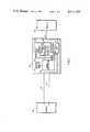
- FIG. 1is a block diagram illustrating the measurement and computation system of the present invention.
- FIG. 2is a schematic diagram which illustrates one of the LED/photodetector arrays used to determine coin diameters.
- FIG. 3is a timing diagram of a given coin moving through two arrays of the type illustrated in FIG. 2.
- FIG. 4is a flow chart illustrating the sequential operations performed by the system, including a microcomputer, in measuring the four time intervals involved whenever a coin is presented at the emitter/detector arrays; further, in computing the diameters of given coins from the times measured, testing the coins against valid sizes and valuations, incrementing the revenue total, and displaying same.
- FIG. 5is an alternate embodiment of the present invention involving a dual beam method.
- FIG. 1there is seen a block diagram depicting a complete system in accordance with the present invention.
- Such systemcomprises a pair of arrays 10, a microcomputer 40, and a display means 70.
- a pair of lines 12 and 14provide communication between the pair of arrays 10 respectively designated A and B, and the microcomputer 40; the output of the microcomputer 40 communicates with the display means 70 by way of an output line 72.
- the microcomputer 40can comprise a microprocessor 42, for example, in the form of an integrated circuit chip known as a 6800 microprocessor, manufactured by the Motorola Corporation.
- This microprocessor 42contains the logic and arithmetic circuitry for controlling the system.
- a clock generator 44 for timing purposesis connected to the microprocessor.
- Interconnectionis established between the microprocessor and a read only memory 46 by a bidirectional data bus 48.
- the read only memory 46 (ROM)is a storage device containing the program and data for determining the actions of the microprocessor 42.
- the bidirectional data bus 48also interconnects the microprocessor and a random access memory unit 50 (RAM), which is a read-write memory used by the microprocessor for temporary storage of data.
- RAMrandom access memory unit
- a peripheral interface unit 52is also coupled by means of the bidirectional data bus 48 to the microprocessor 42.
- Such peripheral interface unitfunctions to allow access between the microprocessor, the several components already noted, and the several input and outputs included.
- the input lines 12 and 14are connected directly to the peripheral interface unit 52, while the output of the interface unit is coupled to the display means 70 by line 72.
- An address bus 54couples the microprocessor 42 to the aforenoted components of the microcomputer so as to provide addressing information to those components: namely, to the read only memory 46, the random access memory 50; and also to the peripheral interface unit 52. This is accomplished by means well understood in the art and which for clarity have not been illustrated. However, such means are described in publications such as the "M6800 Microcomputer System Design Data” published by Motorola in 1976, which publication is incorporated herein by reference.
- the address bus 54provides three bits to an address decoder of conventional type, not illustrated, which converts those three bits to a 1-out-of-8 code for determining the particular device being accessed.
- the address bus 54further provides twelve bits for selecting the particular memory element or register being accessed within the device selected by the decoder.
- FIG. 2there is seen a schematic diagram of one of the pair of arrays 10, previously seen in block form in FIG. 1.
- the particular array illustratedis designated the A array, and an identical B array is also provided.
- a and B arraysfulfills the principal objects of the present invention; that is, to determine the entrance and exit velocities of the coins or tokens under free fall conditions by twice measuring the time taken by a given coin to traverse a fixed distance (leading edge/trailing edge), and further to measure the time between a first occlusion, when the coin passes the first array and a second occlusion when it passes the second array. This is accomplished by having the two arrays A and B in a vertical stacked relationship, the distance therebetween being designated G (FIG. 3).
- Each of the arrays A and Bcomprises a series of light emitting diodes 16, typically nine in number, connected to a source of voltage +V by way of respective resistors 18.
- the series of diodes 16is driven by output signals on line 20, such output signals appearing at the output of a drive amplifier 22 which is provided at its input with control line 24 and a ground line 26. At appropriate times the array is turned on by means of this control line 24.
- a corresponding series of photodiode detectors 28is horizontally aligned opposite the respective light emitting diodes 16. These photodiodes are connected to the inputs of sense amplifiers 30, the outputs of which include logic devices, and are joined in common to the output line 12 previously noted. An appropriate +V voltage source is connected to each of the amplifiers 30 and likewise a ground connection is made to each amplifier (indicated by dotted lines to other than the first amplifier on the right).
- a pair of apertured plates 32 and 34is placed between the opposing arrays of LEDs 16 and photodiodes 28. This arrangement constricts the light path so that the individual light beams 36 result, thereby permitting a more accurate determination of a given coin's position when the light beam is interrupted.
- a coinwill travel between the pair of apertured plates 32 and 34, which serves to define a guideway, with its flat faces perpendicular to the direction of the light beams 36. Accordingly, one or more of the light beams in each of the arrays will be intercepted by the free fall of such coin.
- a chute not illustratedis utilized to feed the coins to the first or A array level.
- FIG. 3there is illustrated diagrammatically the two arrays A and B spaced apart by the gap G.
- the events b, c, d, and eare four events of transition.
- the point at which the coin first interrupts a light beam 36 in the A arrayis the event b.
- the leading edge of the coinis seen to be just reaching the A array.
- the coinis just entering or reaching the B array, while at event d the coin is exiting or leaving the A array and further, at event e, the trailing edge is exiting the B array. Then, at f, the coin has traveled well beyond both arrays.
- the output signal on the lines 12 and 14 from the arrays A and B respectivelyis depicted in the lower part of FIG. 3 with the same events just noted, i.e., a, b, c, d, e, and f being shown thereon. Accordingly, it will be understood that there is a relatively high level signal during event a when the coin having diameter D has not yet reached the upper array A.
- the time interval between events b and cis the time it took the coin to traverse the distance of gap G. Therefore, this time is representative of the entrance velocity V, of the coin, the distance G being a constant. It will also be apparent from FIG. 3 that the time interval between events b and d (second time interval) is the time it took an object to traverse array A. From this, it will be understood that the first time interval representing the entrance velocity V, (from event b to event c), taken together with this second time interval (from event b to event d), is sufficient to determine the apparent entrance diameter D, of a given coin.
- the apparent entrance diametercan be computed from measurements of the first and second time intervals on a "real time” basis utilizing the microcomputer 40 already briefly described. This is accomplished by multiplying the velocity (the inverse of the first time interval) by the second time interval; or for the sake of simplicity, dividing the second time interval directly by the first time interval.
- time interval between events d and ecorresponding to the time it takes the trailing edge of a given coin to traverse the distance or gap G, is representative of the exit velocity of a coin passing through the system.
- This time intervalcan be divided into the interval from events c to e and thus compute the apparent exit diameter of the coin. The two measurements can thus be averaged to obtain more accurate results, one of which corrects for accelerations due to gravity.
- the averaging methodyields very accurate results if the coin is permitted to free fall at least one inch before encountering the first array (A). This applies only if the coin is initially at rest. Considerably shorter distances are required if the coin has increasingly higher initial velocities. If a coin must be measured from a rest velocity with very little free fall prior to entering the measurement system then acceleration factors must be applied to yield consistent results.
- FIG. 4the operations of the system, and particularly of computer 40, are therein illustrated by a flow chart or diagram. It will be seen in this flow chart that the steps of testing the recognized diameter against valid sizes and valuations, then incrementing the revenue total, are to be performed by the computer 40, which then transmits a signal for displaying the revenue total so obtained to the display means 70 seen in FIG. 1.
- this microcomputeris programmed to perform a sequence of operations, seen in FIG. 4, through conventional means forming part of such microcomputer.
- a conventional initial or “starting operation”, designated 100which involves loading the various program counters, table pointers and data pointers with proper values; also zeros are placed in register means 60 forming part of random access memory 50 in FIG. 1.
- This register meansserves to store the various time values, already described, that is T 0 , T 1 , T 2 and T 3 .
- the basic input function of the microcomputeris continuously to test for any change in the input signals on the lines 12 and 14 connected from the arrays A and B respectively.
- Decisional or yes/no blocks 102 and 104designate the operations to implement this function.
- Included as part of microcomputer 40are comparator means for ascertaining when such a change has taken place.
- the implementation consequent to testing for a B signal changeis achieved by the operations designated 114, 116, 118, and 120.
- T 1a time value
- T 3a time value
- FIG. 5there is illustrated an alternate embodiment of the array scheme for the present invention.
- This arrangementinvolves a dual beam method or system in place of the multiple beams for each of the arrays A and B previously seen in FIG. 2.
- the coin 200is seen to have its faces parallel with a pair of light beams 202 and 204 as the coin moves downwardly, rather than intercepting light beams perpendicular to its faces.
- This methodhas the advantage of a substantial reduction in the components required; however, an increased restriction is placed on the path which the coin may follow. It will be manifest that the same essential principle is involved in FIG.
- the light beams 202 and 204which are produced by respective light emitting diodes 206 and 208, function for the same purpose as those in the arrangement of FIG. 2; likewise, the photodiode detectors 210 and 212 normally receive the respective light beams but are occluded as coins or other objects pass by the arrays.
- the systemin essence, incorporates an arrangement for detecting the presence of coins and computing their diameters from time interval measurements which represent the velocity under free-fall conditions, and measurements of time intervals during which each of two detecting levels is passed by the coins.
Landscapes
- Physics & Mathematics (AREA)
- General Physics & Mathematics (AREA)
- Testing Of Coins (AREA)
Abstract
Description
Claims (18)
Priority Applications (2)
| Application Number | Priority Date | Filing Date | Title |
|---|---|---|---|
| US06/385,600US4474281A (en) | 1982-06-07 | 1982-06-07 | Apparatus and method for coin diameter computation |
| CA000429770ACA1181853A (en) | 1982-06-07 | 1983-06-06 | Apparatus and method for coin diameter computation |
Applications Claiming Priority (1)
| Application Number | Priority Date | Filing Date | Title |
|---|---|---|---|
| US06/385,600US4474281A (en) | 1982-06-07 | 1982-06-07 | Apparatus and method for coin diameter computation |
Publications (1)
| Publication Number | Publication Date |
|---|---|
| US4474281Atrue US4474281A (en) | 1984-10-02 |
Family
ID=23522093
Family Applications (1)
| Application Number | Title | Priority Date | Filing Date |
|---|---|---|---|
| US06/385,600Expired - LifetimeUS4474281A (en) | 1982-06-07 | 1982-06-07 | Apparatus and method for coin diameter computation |
Country Status (2)
| Country | Link |
|---|---|
| US (1) | US4474281A (en) |
| CA (1) | CA1181853A (en) |
Cited By (41)
| Publication number | Priority date | Publication date | Assignee | Title |
|---|---|---|---|---|
| US4646904A (en)* | 1985-09-05 | 1987-03-03 | Coin Acceptors, Inc. | Coin sizing means and method |
| US4848556A (en)* | 1985-04-08 | 1989-07-18 | Qonaar Corporation | Low power coin discrimination apparatus |
| WO1991018371A1 (en)* | 1990-05-14 | 1991-11-28 | Cummins-Allison Corp. | Coin sorter with automatic bag-switching or stopping |
| US5097934A (en)* | 1990-03-09 | 1992-03-24 | Automatic Toll Systems, Inc. | Coin sensing apparatus |
| EP0483451A1 (en)* | 1990-11-02 | 1992-05-06 | Marconi Automazione S.P.A. | Method and an apparatus for identifying coins |
| ES2043544A2 (en)* | 1992-04-21 | 1993-12-16 | Comercial Cocamatic S A | Improvements to electronic coin-sorting/-testing devices (purses) |
| US5360095A (en)* | 1992-04-07 | 1994-11-01 | Pom Incorporated | Power conserving electronic parking meter |
| US5392892A (en)* | 1992-04-14 | 1995-02-28 | Nsm Aktiengesellschaft | Device for the measurement of the diameter of circular objects |
| US5460256A (en)* | 1994-03-31 | 1995-10-24 | Coin Acceptors, Inc. | Coin sensor device |
| EP0694888A1 (en)* | 1994-07-29 | 1996-01-31 | Landis & Gyr Technology Innovation AG | Device for testing coins or other flat objects |
| US5507379A (en)* | 1990-05-14 | 1996-04-16 | Cummins-Allison Corp. | Coin handling system with coin sensor discriminator |
| US5542880A (en)* | 1990-05-14 | 1996-08-06 | Cummins-Allison Corp. | Coin handling system with shunting mechanism |
| US5573099A (en)* | 1994-01-14 | 1996-11-12 | J. J. Mackay Canada Limited | Apparatus and method for identifying metallic tokens and coins |
| WO1997004424A1 (en)* | 1995-07-14 | 1997-02-06 | Coin Controls Ltd. | Coin validator |
| US5630494A (en)* | 1995-03-07 | 1997-05-20 | Cummins-Allison Corp. | Coin discrimination sensor and coin handling system |
| US5782686A (en)* | 1995-12-04 | 1998-07-21 | Cummins-Allison Corp. | Disc coin sorter with slotted exit channels |
| US5865673A (en)* | 1996-01-11 | 1999-02-02 | Cummins-Allison Corp. | Coin sorter |
| ES2127155A1 (en)* | 1997-09-03 | 1999-04-01 | Azkoyen Ind Sa | Process and apparatus for the identification of metal disc-shaped pieces |
| US5992602A (en)* | 1996-01-11 | 1999-11-30 | De La Rue Systems Americas Corporation | Coin recognition and off-sorting in a coin sorter |
| US5997395A (en)* | 1998-03-17 | 1999-12-07 | Cummins-Allison Corp. | High speed coin sorter having a reduced size |
| US6039164A (en)* | 1998-04-13 | 2000-03-21 | Agent Systems, Inc. | Automatic validating farebox system and method |
| EP0996098A2 (en)* | 1996-05-21 | 2000-04-26 | Ezio Panzeri | Coin testing apparatus and method |
| US6059650A (en)* | 1998-04-13 | 2000-05-09 | Agent Systems, Inc. | System and method for coin singulation |
| US6125988A (en)* | 1998-04-13 | 2000-10-03 | Agent Systems, Inc. | System and method for providing farebox accountability |
| US6171182B1 (en) | 1992-09-25 | 2001-01-09 | Cummins-Allison Corp. | Coin handling system with shunting mechanism |
| US6223877B1 (en) | 1996-07-29 | 2001-05-01 | Qvex, Inc. | Coin validation apparatus |
| US20040092222A1 (en)* | 2002-11-07 | 2004-05-13 | Bogdan Kowalczyk | Stationary head for a disc-type coin processing device having a solid lubricant disposed thereon |
| US7635059B1 (en) | 2000-02-02 | 2009-12-22 | Imonex Services, Inc. | Apparatus and method for rejecting jammed coins |
| GB2488376A (en)* | 2011-02-28 | 2012-08-29 | Ezio Panzeri | Optical coin sensor apparatus |
| US8395532B2 (en) | 2008-04-25 | 2013-03-12 | J.J. Mackay Canada Limited | Data collection system for electronic parking meters |
| USD705090S1 (en) | 2012-04-02 | 2014-05-20 | J.J. Mackay Canada Limited | Single space parking meter |
| US8727207B1 (en) | 1995-04-06 | 2014-05-20 | J.J. Mackay Canada Limited | Electronic parking meter |
| US8770371B2 (en) | 2011-03-03 | 2014-07-08 | J.J. Mackay Canada Limited | Single space parking meter and removable single space parking meter mechanism |
| US9494922B2 (en) | 2008-12-23 | 2016-11-15 | J.J. Mackay Canada Limited | Single space wireless parking with improved antenna placements |
| US9652921B2 (en) | 2015-06-16 | 2017-05-16 | J.J. Mackay Canada Limited | Coin chute with anti-fishing assembly |
| USD863075S1 (en) | 2015-10-16 | 2019-10-15 | J.J. Mackay Canada Limited | Parking meter |
| USRE48566E1 (en) | 2015-07-15 | 2021-05-25 | J.J. Mackay Canada Limited | Parking meter |
| US11762479B2 (en) | 2019-01-30 | 2023-09-19 | J.J. Mackay Canada Limited | SPI keyboard module for a parking meter and a parking meter having an SPI keyboard module |
| US11922756B2 (en) | 2019-01-30 | 2024-03-05 | J.J. Mackay Canada Limited | Parking meter having touchscreen display |
| US11972654B2 (en) | 2015-08-11 | 2024-04-30 | J.J. Mackay Canada Limited | Lightweight vandal resistant parking meter |
| US12417669B2 (en) | 2015-08-08 | 2025-09-16 | J.J. Mackay Canada Limited | Lighweight vandal resistent parking meter |
Citations (7)
| Publication number | Priority date | Publication date | Assignee | Title |
|---|---|---|---|---|
| US2903117A (en)* | 1958-08-19 | 1959-09-08 | Bell Telephone Labor Inc | Coin testing mechanism |
| US3738469A (en)* | 1969-08-22 | 1973-06-12 | G Prumm | Tester for different types of coins |
| US3752168A (en)* | 1970-04-03 | 1973-08-14 | Ardac Inc | Coin orienting, sorting and dispensing apparatus |
| US3788440A (en)* | 1970-10-23 | 1974-01-29 | Cit Alcatel | Coin operated apparatus |
| US3797307A (en)* | 1972-01-20 | 1974-03-19 | Little Inc A | Coin discriminator |
| US3980168A (en)* | 1972-10-12 | 1976-09-14 | Michael John Knight | Method and apparatus for authenticating and identifying coins |
| US4249648A (en)* | 1978-04-27 | 1981-02-10 | Keene Corporation | Token identifying system |
- 1982
- 1982-06-07USUS06/385,600patent/US4474281A/ennot_activeExpired - Lifetime
- 1983
- 1983-06-06CACA000429770Apatent/CA1181853A/ennot_activeExpired
Patent Citations (7)
| Publication number | Priority date | Publication date | Assignee | Title |
|---|---|---|---|---|
| US2903117A (en)* | 1958-08-19 | 1959-09-08 | Bell Telephone Labor Inc | Coin testing mechanism |
| US3738469A (en)* | 1969-08-22 | 1973-06-12 | G Prumm | Tester for different types of coins |
| US3752168A (en)* | 1970-04-03 | 1973-08-14 | Ardac Inc | Coin orienting, sorting and dispensing apparatus |
| US3788440A (en)* | 1970-10-23 | 1974-01-29 | Cit Alcatel | Coin operated apparatus |
| US3797307A (en)* | 1972-01-20 | 1974-03-19 | Little Inc A | Coin discriminator |
| US3980168A (en)* | 1972-10-12 | 1976-09-14 | Michael John Knight | Method and apparatus for authenticating and identifying coins |
| US4249648A (en)* | 1978-04-27 | 1981-02-10 | Keene Corporation | Token identifying system |
Cited By (73)
| Publication number | Priority date | Publication date | Assignee | Title |
|---|---|---|---|---|
| US4848556A (en)* | 1985-04-08 | 1989-07-18 | Qonaar Corporation | Low power coin discrimination apparatus |
| US4646904A (en)* | 1985-09-05 | 1987-03-03 | Coin Acceptors, Inc. | Coin sizing means and method |
| US5097934A (en)* | 1990-03-09 | 1992-03-24 | Automatic Toll Systems, Inc. | Coin sensing apparatus |
| US5507379A (en)* | 1990-05-14 | 1996-04-16 | Cummins-Allison Corp. | Coin handling system with coin sensor discriminator |
| WO1991018371A1 (en)* | 1990-05-14 | 1991-11-28 | Cummins-Allison Corp. | Coin sorter with automatic bag-switching or stopping |
| US5141443A (en)* | 1990-05-14 | 1992-08-25 | Cummins-Allison Corp. | Coin sorter with automatic bag-switching or stopping |
| US5542880A (en)* | 1990-05-14 | 1996-08-06 | Cummins-Allison Corp. | Coin handling system with shunting mechanism |
| US5277651A (en)* | 1990-05-14 | 1994-01-11 | Cummins-Allison Corp. | Coin sorter with automatic bag-switching or stopping |
| EP0483451A1 (en)* | 1990-11-02 | 1992-05-06 | Marconi Automazione S.P.A. | Method and an apparatus for identifying coins |
| US5360095A (en)* | 1992-04-07 | 1994-11-01 | Pom Incorporated | Power conserving electronic parking meter |
| US5475373A (en)* | 1992-04-07 | 1995-12-12 | Pom, Inc. | Power conserving electronic parking meter |
| US5392892A (en)* | 1992-04-14 | 1995-02-28 | Nsm Aktiengesellschaft | Device for the measurement of the diameter of circular objects |
| ES2043544A2 (en)* | 1992-04-21 | 1993-12-16 | Comercial Cocamatic S A | Improvements to electronic coin-sorting/-testing devices (purses) |
| US6171182B1 (en) | 1992-09-25 | 2001-01-09 | Cummins-Allison Corp. | Coin handling system with shunting mechanism |
| US5573099A (en)* | 1994-01-14 | 1996-11-12 | J. J. Mackay Canada Limited | Apparatus and method for identifying metallic tokens and coins |
| US5460256A (en)* | 1994-03-31 | 1995-10-24 | Coin Acceptors, Inc. | Coin sensor device |
| EP0694888A1 (en)* | 1994-07-29 | 1996-01-31 | Landis & Gyr Technology Innovation AG | Device for testing coins or other flat objects |
| US5743373A (en)* | 1995-03-07 | 1998-04-28 | Cummins-Allison Corp. | Coin discrimination sensor and coin handling system |
| US5630494A (en)* | 1995-03-07 | 1997-05-20 | Cummins-Allison Corp. | Coin discrimination sensor and coin handling system |
| US8727207B1 (en) | 1995-04-06 | 2014-05-20 | J.J. Mackay Canada Limited | Electronic parking meter |
| US6467604B1 (en)* | 1995-07-14 | 2002-10-22 | Coin Controls, Ltd. | Apparatus and method for determining the validity of a coin |
| WO1997004424A1 (en)* | 1995-07-14 | 1997-02-06 | Coin Controls Ltd. | Coin validator |
| US6053300A (en)* | 1995-07-14 | 2000-04-25 | Coins Controls Ltd. | Apparatus and method for determining the validity of a coin |
| US5782686A (en)* | 1995-12-04 | 1998-07-21 | Cummins-Allison Corp. | Disc coin sorter with slotted exit channels |
| US6042470A (en)* | 1996-01-11 | 2000-03-28 | Cummins-Allison Corp. | Coin sorter |
| US6039644A (en)* | 1996-01-11 | 2000-03-21 | Cummins-Allison Corp. | Coin sorter |
| US5992602A (en)* | 1996-01-11 | 1999-11-30 | De La Rue Systems Americas Corporation | Coin recognition and off-sorting in a coin sorter |
| US5865673A (en)* | 1996-01-11 | 1999-02-02 | Cummins-Allison Corp. | Coin sorter |
| EP0996098A2 (en)* | 1996-05-21 | 2000-04-26 | Ezio Panzeri | Coin testing apparatus and method |
| US6223877B1 (en) | 1996-07-29 | 2001-05-01 | Qvex, Inc. | Coin validation apparatus |
| ES2127155A1 (en)* | 1997-09-03 | 1999-04-01 | Azkoyen Ind Sa | Process and apparatus for the identification of metal disc-shaped pieces |
| US5997395A (en)* | 1998-03-17 | 1999-12-07 | Cummins-Allison Corp. | High speed coin sorter having a reduced size |
| US6139418A (en)* | 1998-03-17 | 2000-10-31 | Cummins-Allison Corp. | High speed coin sorter having a reduced size |
| US6612921B2 (en) | 1998-03-17 | 2003-09-02 | Cummins-Allison Corp. | High speed coin sorter having a reduced size |
| US6039164A (en)* | 1998-04-13 | 2000-03-21 | Agent Systems, Inc. | Automatic validating farebox system and method |
| US6059650A (en)* | 1998-04-13 | 2000-05-09 | Agent Systems, Inc. | System and method for coin singulation |
| US6125988A (en)* | 1998-04-13 | 2000-10-03 | Agent Systems, Inc. | System and method for providing farebox accountability |
| US7635059B1 (en) | 2000-02-02 | 2009-12-22 | Imonex Services, Inc. | Apparatus and method for rejecting jammed coins |
| US20040092222A1 (en)* | 2002-11-07 | 2004-05-13 | Bogdan Kowalczyk | Stationary head for a disc-type coin processing device having a solid lubricant disposed thereon |
| US8395532B2 (en) | 2008-04-25 | 2013-03-12 | J.J. Mackay Canada Limited | Data collection system for electronic parking meters |
| US9494922B2 (en) | 2008-12-23 | 2016-11-15 | J.J. Mackay Canada Limited | Single space wireless parking with improved antenna placements |
| US10998612B2 (en) | 2008-12-23 | 2021-05-04 | J.J. Mackay Canada Limited | Single space wireless parking with improved antenna placements |
| US10573953B2 (en) | 2008-12-23 | 2020-02-25 | J.J. Mackay Canada Limited | Single space wireless parking with improved antenna placements |
| US11670835B2 (en) | 2008-12-23 | 2023-06-06 | J.J Mackay Canada Limited | Single space wireless parking with improved antenna placements |
| US12368227B2 (en) | 2008-12-23 | 2025-07-22 | J.J. Mackay Canada Limited | Single space wireless parking with improved antenna placements |
| US10141629B2 (en) | 2008-12-23 | 2018-11-27 | J.J. Mackay Canada Limited | Single space wireless parking with improved antenna placements |
| GB2488376A (en)* | 2011-02-28 | 2012-08-29 | Ezio Panzeri | Optical coin sensor apparatus |
| US12008856B2 (en) | 2011-03-03 | 2024-06-11 | J.J. Mackay Canada Limited | Single space parking meter and removable single space parking meter mechanism |
| US12430978B2 (en) | 2011-03-03 | 2025-09-30 | J.J. Mackay Canada Limited | Parking meter with contactless payment |
| US9842455B2 (en) | 2011-03-03 | 2017-12-12 | J.J. Mackay Canada Limited | Single space parking meter and removable single space parking meter mechanism |
| US9934645B2 (en) | 2011-03-03 | 2018-04-03 | J.J. Mackay Canada Limited | Parking meter with contactless payment |
| US9443236B2 (en) | 2011-03-03 | 2016-09-13 | J.J. Mackay Canada Limited | Single space parking meter and removable single space parking meter mechanism |
| US10192388B2 (en) | 2011-03-03 | 2019-01-29 | J.J. Mackay Canada Limited | Single space parking meter and removable single space parking meter mechanism |
| US10424147B2 (en) | 2011-03-03 | 2019-09-24 | J.J. Mackay Canada Limited | Parking meter with contactless payment |
| US10861278B2 (en) | 2011-03-03 | 2020-12-08 | J.J. Mackay Canada Limited | Parking meter with contactless payment |
| US9406056B2 (en) | 2011-03-03 | 2016-08-02 | J.J. Mackay Canada Limited | Parking meter with contactless payment |
| US8770371B2 (en) | 2011-03-03 | 2014-07-08 | J.J. Mackay Canada Limited | Single space parking meter and removable single space parking meter mechanism |
| US11699321B2 (en) | 2011-03-03 | 2023-07-11 | J.J Mackay Canada Limited | Parking meter with contactless payment |
| US8807317B2 (en) | 2011-03-03 | 2014-08-19 | J.J. Mackay Canada Limited | Single space parking meter and removable single space parking meter mechanism |
| USD716157S1 (en) | 2012-04-02 | 2014-10-28 | J.J. Mackay Canada Limited | Single space parking meter |
| USD705090S1 (en) | 2012-04-02 | 2014-05-20 | J.J. Mackay Canada Limited | Single space parking meter |
| US9652921B2 (en) | 2015-06-16 | 2017-05-16 | J.J. Mackay Canada Limited | Coin chute with anti-fishing assembly |
| USRE48566E1 (en) | 2015-07-15 | 2021-05-25 | J.J. Mackay Canada Limited | Parking meter |
| US12417669B2 (en) | 2015-08-08 | 2025-09-16 | J.J. Mackay Canada Limited | Lighweight vandal resistent parking meter |
| US11972654B2 (en) | 2015-08-11 | 2024-04-30 | J.J. Mackay Canada Limited | Lightweight vandal resistant parking meter |
| US11978300B2 (en) | 2015-08-11 | 2024-05-07 | J.J. Mackay Canada Limited | Single space parking meter |
| USD863988S1 (en) | 2015-10-16 | 2019-10-22 | J.J. Mackay Canada Limited | Parking meter |
| USD863987S1 (en) | 2015-10-16 | 2019-10-22 | J.J. Mackay Canada Limited | Parking meter |
| USD863076S1 (en) | 2015-10-16 | 2019-10-15 | J. J. Mackay Canada Limited | Parking meter |
| USD863074S1 (en) | 2015-10-16 | 2019-10-15 | J. J. Mackay Canada Limited | Parking meter |
| USD863075S1 (en) | 2015-10-16 | 2019-10-15 | J.J. Mackay Canada Limited | Parking meter |
| US11762479B2 (en) | 2019-01-30 | 2023-09-19 | J.J. Mackay Canada Limited | SPI keyboard module for a parking meter and a parking meter having an SPI keyboard module |
| US11922756B2 (en) | 2019-01-30 | 2024-03-05 | J.J. Mackay Canada Limited | Parking meter having touchscreen display |
Also Published As
| Publication number | Publication date |
|---|---|
| CA1181853A (en) | 1985-01-29 |
Similar Documents
| Publication | Publication Date | Title |
|---|---|---|
| US4474281A (en) | Apparatus and method for coin diameter computation | |
| CA1206618A (en) | Electronic coin measurement apparatus | |
| US4585936A (en) | Optical process for determining the dimensions of an object in relative movement, and more particularly of a coin in a pre-payment apparatus | |
| US3653481A (en) | Electrical/electronic coin or token indentification system | |
| US4509633A (en) | Electronic coin validator with improved diameter sensing apparatus | |
| US4249648A (en) | Token identifying system | |
| US4556140A (en) | Method and apparatus for discriminating coins or bank notes | |
| US4228811A (en) | Apparatus for controlling a coin sorting machine | |
| US4577744A (en) | Multicoin discriminator | |
| JP2599347B2 (en) | Coil measuring method | |
| JPH0427595B2 (en) | ||
| US3650397A (en) | System for inspecting and classifying objects such as screws, bolts and the like while in motion | |
| US5460256A (en) | Coin sensor device | |
| GB2140954A (en) | Coin tube monitor means | |
| US3754558A (en) | Coin processing apparatus with jam detection system | |
| US3797628A (en) | Device and method for testing coins employing velocity determining means | |
| US4109774A (en) | Control system for a vending machine | |
| US3699981A (en) | Coin value determining apparatus and system | |
| US4100599A (en) | Method and apparatus for determining velocity of a moving member | |
| WO1992009056A1 (en) | Coin discrimination apparatus with optical sensor | |
| CA1272657A (en) | Coin discriminator | |
| GB1272560A (en) | Coin selector for determining the authenticity and denomination of coins | |
| US3848614A (en) | Coin processor having error-indicating system | |
| US3785386A (en) | Sorting and counting apparatus | |
| US4329576A (en) | Data storage means and reading system therefor |
Legal Events
| Date | Code | Title | Description |
|---|---|---|---|
| AS | Assignment | Owner name:GENERAL SIGNAL CORPORATION, A CORP. OF N.Y. Free format text:ASSIGNMENT OF ASSIGNORS INTEREST.;ASSIGNORS:ROBERTS, MICHAEL;SLOBODZIAN, GREGORY;REEL/FRAME:004012/0852 Effective date:19820602 | |
| STCF | Information on status: patent grant | Free format text:PATENTED CASE | |
| FEPP | Fee payment procedure | Free format text:PAYOR NUMBER ASSIGNED (ORIGINAL EVENT CODE: ASPN); ENTITY STATUS OF PATENT OWNER: LARGE ENTITY | |
| FPAY | Fee payment | Year of fee payment:4 | |
| FPAY | Fee payment | Year of fee payment:8 | |
| FPAY | Fee payment | Year of fee payment:12 | |
| FEPP | Fee payment procedure | Free format text:PAYER NUMBER DE-ASSIGNED (ORIGINAL EVENT CODE: RMPN); ENTITY STATUS OF PATENT OWNER: LARGE ENTITY Free format text:PAYOR NUMBER ASSIGNED (ORIGINAL EVENT CODE: ASPN); ENTITY STATUS OF PATENT OWNER: LARGE ENTITY | |
| AS | Assignment | Owner name:SAC CORP. (DE CORP.), MICHIGAN Free format text:MERGER;ASSIGNOR:GENERAL SIGNAL CORPORATION (NY CORP.);REEL/FRAME:010937/0538 Effective date:19981006 | |
| AS | Assignment | Owner name:GENERAL SIGNAL CORPORATION (DE CORP.), MICHIGAN Free format text:CHANGE OF NAME;ASSIGNOR:SAC CORP. (DE CORP.);REEL/FRAME:010927/0925 Effective date:19981006 | |
| AS | Assignment | Owner name:CHASE MANHATTAN BANK, THE, AS COLLATERAL AGENT, NE Free format text:CONDITIONAL ASSIGNMENT OF AND SECURITY INTEREST IN PATENT RIGHTS;ASSIGNOR:GSTC DEVELOPMENT CORPORATION, A CORP. OF DELAWARE;REEL/FRAME:011035/0887 Effective date:20000613 | |
| AS | Assignment | Owner name:GENEAL SIGNAL TECHNOLOGY CORPORATION (DE CORP), MI Free format text:ASSIGNMENT OF ASSIGNORS INTEREST;ASSIGNOR:GENERAL SIGNAL CORPORATION (DE CORP.);REEL/FRAME:011122/0849 Effective date:20000101 Owner name:GSTC DEVELOPMENT CORPORATION (DE CORP.), MICHIGAN Free format text:ASSIGNMENT OF ASSIGNORS INTEREST;ASSIGNOR:GENERAL SIGNAL TECHNOLOGY CORPORATION;REEL/FRAME:011122/0927 Effective date:20000101 | |
| AS | Assignment | Owner name:GSTC DEVELOPMENT CORPORATION (DE CORP.), MICHIGAN Free format text:CORRECTIVE ASSIGNMENT PREVIOUSLY RECORDED AT REEL 011122 FRAME 0927;ASSIGNOR:GENERAL SIGNAL TECHNOLOGY CORPORATION (DE CORP.);REEL/FRAME:012043/0695 Effective date:20000101 | |
| AS | Assignment | Owner name:GSLE SUBCO LLC (FORMERLY KNOWN AS GSTC DEVELOPMENT Free format text:TERMINATION AND RELEASE OF SECURITY INTEREST IN PATENT RIGHTS (PREVIOUSLY RECORDED AT REEL 11035 FRAME 0887);ASSIGNOR:JPMORGAN CHASE BANK, N.A., AS COLLATERAL AGENT;REEL/FRAME:016844/0351 Effective date:20051118 |