US4474236A - Method and apparatus for remote installations of dual tubing strings in a subsea well - Google Patents
Method and apparatus for remote installations of dual tubing strings in a subsea wellDownload PDFInfo
- Publication number
- US4474236A US4474236AUS06/469,093US46909383AUS4474236AUS 4474236 AUS4474236 AUS 4474236AUS 46909383 AUS46909383 AUS 46909383AUS 4474236 AUS4474236 AUS 4474236A
- Authority
- US
- United States
- Prior art keywords
- tubing hanger
- main
- bore
- service line
- running
- Prior art date
- Legal status (The legal status is an assumption and is not a legal conclusion. Google has not performed a legal analysis and makes no representation as to the accuracy of the status listed.)
- Expired - Fee Related
Links
- 230000009977dual effectEffects0.000titleclaimsabstractdescription20
- 238000000034methodMethods0.000titleclaimsabstractdescription13
- 238000009434installationMethods0.000titledescription2
- 238000012360testing methodMethods0.000claimsabstractdescription30
- 238000004519manufacturing processMethods0.000claimsabstractdescription29
- KJLPSBMDOIVXSN-UHFFFAOYSA-N4-[4-[2-[4-(3,4-dicarboxyphenoxy)phenyl]propan-2-yl]phenoxy]phthalic acidChemical compoundC=1C=C(OC=2C=C(C(C(O)=O)=CC=2)C(O)=O)C=CC=1C(C)(C)C(C=C1)=CC=C1OC1=CC=C(C(O)=O)C(C(O)=O)=C1KJLPSBMDOIVXSN-UHFFFAOYSA-N0.000claimsdescription12
- 238000007789sealingMethods0.000description27
- 238000010276constructionMethods0.000description6
- 239000007788liquidSubstances0.000description4
- 239000004020conductorSubstances0.000description3
- 238000010008shearingMethods0.000description3
- 239000012530fluidSubstances0.000description2
- 238000003825pressingMethods0.000description2
- 241000191291Abies albaSpecies0.000description1
- 238000004891communicationMethods0.000description1
- 239000002131composite materialSubstances0.000description1
- 239000000470constituentSubstances0.000description1
- 238000013461designMethods0.000description1
- 238000010586diagramMethods0.000description1
- 230000000694effectsEffects0.000description1
- 238000011835investigationMethods0.000description1
- 230000013011matingEffects0.000description1
- 238000012986modificationMethods0.000description1
- 230000004048modificationEffects0.000description1
- 238000011017operating methodMethods0.000description1
- 230000000717retained effectEffects0.000description1
- XLYOFNOQVPJJNP-UHFFFAOYSA-NwaterSubstancesOXLYOFNOQVPJJNP-UHFFFAOYSA-N0.000description1
Images


Classifications
- E—FIXED CONSTRUCTIONS
- E21—EARTH OR ROCK DRILLING; MINING
- E21B—EARTH OR ROCK DRILLING; OBTAINING OIL, GAS, WATER, SOLUBLE OR MELTABLE MATERIALS OR A SLURRY OF MINERALS FROM WELLS
- E21B33/00—Sealing or packing boreholes or wells
- E21B33/02—Surface sealing or packing
- E21B33/03—Well heads; Setting-up thereof
- E21B33/04—Casing heads; Suspending casings or tubings in well heads
- E21B33/047—Casing heads; Suspending casings or tubings in well heads for plural tubing strings
Definitions
- the present inventionrelates to a method and apparatus for remote installation of dual tubing strings in a subsea well with all operations remote controlled from the surface.
- the inventionprovides a method for completing a well having production and service strings of different sizes including the steps of running the production string on a main tubing hanger and maintaining control with a variable bore blowout preventer and then running the service string into the tubing hanger and maintaining control with a dual bore blowout preventer with the two strings oriented. Orientation is effected by an orientation bushing as the main tubing hanger is landed.
- a service line boreproviding means for locating a service line tubing hanger and for receiving a service line tubing hanger running tool.
- This toolcomprises:
- an upward tubular extensionaligned with the main bore which, when the hanger is seated, extends upwardly through a dual bore blowout preventer and contains hydraulic pressure ducts for testing and control of the main and service line tubing hangers and presents an exterior adapted for cooperation with the blowout preventer rams,
- connection means at the top of the extensionfor connection to pressure hoses
- port meansincluding ports at the service line bore to register with ports on the service line tubing hanger and for a running tool therefor for control and testing of the service line hanger.
- the main object of the inventionis to provide a reliable and relatively simple method and apparatus for completing a well with dual strings of different sizes while maintaining control of the well by blowout preventers as the strings are run.
- Another object of the present inventionis to provide an improved method of installing dual strings of different sizes in a subsea well wherein the strings are run separately.
- a further objectis to provide an improved method of and apparatus for completing a subsea well having production and service strings of different sizes simply and quickly without problems of orientation or sacrificing control of the well.
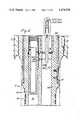
- FIG. 1is a diagrammatic sectional view of a wellhead with a blowout preventer stack, showing production and service tubing strings installed on tubing hangers, with the running tools, running strings and control hoses in position, the section being taken on a diametral plane containing the axes of the production and service strings;
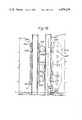
- FIG. 2is a sectional view in more detail of the tubing hangers and running tools and certain adjacent parts: FIG. 2 is divided into four parts, 2A, 2B, 2C and 2D, going from the upper to the lower end;
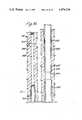
- FIG. 3is a plan view of the apparatus shown in FIG. 2;
- FIG. 4is a sectional view similar to a part of FIG. 2 but showing a dummy service line hanger
- FIG. 5is a partly sectioned side elevation of the top of the main tubing hanger running tool and running strings with a deflector mounted on the hanger;
- FIG. 6is a part-sectional plan view of what is shown in FIG. 5, but illustrating also a guide clamp and control hoses;
- FIG. 7is a longitudinal section, taken on intersecting planes indicated at VII--VII in FIG. 6, showing the guide clamp and, above the centerline, the full-bore annulus connector and a dummy mandrel, FIG. 7 being in two parts, 7A, 7B, to be read 7A above 7B;
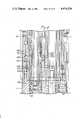
- FIG. 8is a part longitudinal section of the main tubing hanger running tool showing a secondary annulus access line, the figure being again in two parts 8A, 8B, to be read 8A above 8B;
- FIG. 9is a part longitudinal section showing a part of a modified service line running tool with an alternative locking arrangement for the service line hanger.
- FIG. 1there is shown a wellhead designated generally 10, carrying a blowout preventer stack designated generally 12, the stack comprising in sequence going from the bottom to the top, 133/8" casing rams 14, 65/8" and 23/841 dual bore rams 16, variable bore rams 18, and blind shearing rams 20.
- the wellheadcomprises a 30" conductor 22 housing an assembly 24 of casing hangers surmounted by a lockdown seal assembly 26.
- a main tubing hanger designated generally 28is located within the seal assembly 26; an orientation bushing 30 located above the seal assembly rotates the main tubing hanger to a predetermined angular position as the hanger is lowered on to the seal assembly.
- a main tubing hanger running tool 48is connected to the main tubing hanger and has a main bore 50 in alignment with the main bore 32 in the main tubing hanger and also a service line bore 52 in alignment with the service line bore 34 in the main tubing hanger.
- the main tubing hanger running tool 48has an upwardly extending mandrel 54 with a generally cylindrical exterior, which is connected at its upper end, as shown at 55, to a 4" production line running or tie-back string 56.
- the main bore 50 of the main tubing hanger running tool 48extends upwards through the mandrel 54, and the running string 56, bores 50, 32, and the production tubing 38 are all aligned.
- the main tubing; hanger running tool 48provides connections shown generally at 58 for a control hose bundle 60.
- Ductsto be described later and not shown in FIG. 1, extend from the connections 58 within the thickness of the mandrel 54 and into the body of main tubing hanger running tool 48 to supply hydraulic pressure from hoses of bundle 60 for all necessary control and testing functions.
- a deflector 61is mounted on the top of the mandrel 60.
- the main tubing hanger running tool 48is formed with an entry cone 62 to guide the service line string 44 into the service line bore 52.
- the service line tubing hanger 40is connected to a service line tubing hanger running tool 64 seated in the service line bore 34 of the main tubing hanger running tool 48, and this service line tubing hanger running tool is shown connected, at 65, to a 2" service line running or tie-back string 66.
- the service linehas the running string 66, running tool 64, service line tubing hanger 40 and service line tubing 44 all in alignment.
- a dummy service line tubing hanger 40'(FIG. 4) is inserted into the service line bore 34 of the main tubing hanger 28, to act as a plug therein.
- the dummy service line tubing hanger 40'is similar to the service line tubing hanger 40 except that the bore is closed and it is not intended to carry any tubing.
- the main tubing hanger 28is then assembled on a string of 4" production tubing 38, and connected to the main tubing hanger running tool 48.
- the control hose bundle 60is connected to the connections 58 at the top of the mandrel 54.
- the main tubing hanger 28is then landed on the lockdown seal assembly 26 with the aid of the running string 56, after orientation to predetermined position as it passes the orientation bushing 30.
- variable bore pipe rams 18As the production tubing 38 is being run down, control can be exercised by the variable bore pipe rams 18.
- the hanger 28When the hanger 28 is landed on the seal assembly 26 the main tubing hanger running tool 48 presents a cylindrical exterior surface 72 for cooperation with the 133/8" casing ram 14.
- the service line bore 34 in the main tubing hanger 28is closed by the dummy service line tubing hanger 40'.
- the ducts in the mandrel 54 and body of the main tubing hanger running tool 48allow hydraulic pressure to be delivered to piston areas so as to lockdown the main tubing hanger 28, and test the seals 70 between the main tubing hanger 28 and the seal assembly 26.
- a retrieval tool(not shown) is now run down on a service line tubing running string 66 to enter the service line bore 52 and connect to the dummy service line tubing hanger 40'.
- subsea safety valvesmay be set also by hydraulic pressure delivered through hoses of the bundle 60.
- a Christmas tree(not shown) can then be lowered on to the main tubing hanger.
- the main tubing hanger 28has a body 100 with a frustoconical seating portion 102 at its lower end, seating on a corresponding surface 104 of the lockdown seal assembly 26.
- the hanger body 100carries a pair of sealing rings 107 adapted to seal within a cylindrical bore 106 of the lockdown seal assembly 26; sealing rings 107 constitute the previously mentioned seal 70 (FIG. 1).
- the hanger body 100carries an actuating sleeve 108 whose lower end is formed as a series of cam fingers 110.
- a locking ring 112which is a split ring, in its unactivated or retracted condition surrounds the body 100 of the tubing hanger against a shoulder 114 thereof and lies within the outline of the body and sleeve 108 so as to present no obstruction as the hanger is moved through the orienting bushing and lockdown seal assembly.
- the sleeve 108is movable between an upper or unlocked position as illustrated in the left-hand side of the FIG. 2C and the lower or locking position as illustrated in the right-hand side of that figure.
- the cam fingers 110are clear of the locking ring 112 which then adopts its unactivated or retracted position.
- the fingers 110cam out the locking ring 112 so that it extends within a recess 116 in the lockdown seal assembly 26 and prevents upward movement of the tubing hanger.
- Sealing rings 120are provided in the tubing hanger body 100 to form a seal between the body and the locking sleeve 108.
- Shear pins 122 located in bores within the hanger body 100are spring-urged outwardly so that when the locking sleeve 108 moves to locking position, the shear pins move out into recesses 124 in the sleeve to prevent its retraction.
- the lower or casing blowout preventer rams 14are clamped around the cylindrical surface 72 of the main tubing hanger running tool 48 and pressure is applied to the kill line.
- the annulusis thereby pressurized around the main tubing hanger. If the pressure applied is seen to fall off, it may be assumed that there is a leak at the sealing rings 107 and the hanger is removed for investigation. If the pressure is retained, then the sealing rings 107 are assumed to be functioning correctly and the hanger 28 may be locked down.
- the hose bundle 60provides hose connections to the surface for various hose connections 58 on the mandrel 54, among them one designated - UNLOCK - MAIN TUBING, with reference 1008.
- Connection 1008leads to duct 1008g (see below) in the main tubing hanger running tool 48 which in turn connects through space 129 therein with space 130 as best seen in the left-hand side of the FIG. 2C. Sealing rings 132, 134 and 136 are provided on parts, to be described, of the main tubing hanger running tool 48.
- connection 1008is opened.
- the kill line pressurewhich is applied to the space 138 above the actuating sleeve 108 will move it to the locking position, as shown in the right-hand side of the FIG. 2C.
- the hanger body 100is now locked down by virtue of the locking ring 112 extending into the recess 116 in the seal assembly 26.
- the hanger body 100could be unlocked if required by applying pressure to the connection 1008, with the kill line pressure removed. This will move the sleeve 108 to unlocked position, shearing pins 122, and allowing locking ring 112 to retract.
- Service line tubing hanger 40is, as previously mentioned, run on the service line running tool 64 once the main tubing hanger 28 is locked down.
- the service line tubing hangeris generally similar to the main tubing hanger 28 so far as seating and lockdown features are concerned.
- the lower end of the tubing hanger body 200has an annular frustoconical seating surface 202 seating on a corresponding seat 204 on the main tubing hanger body, in the service line bore 34 therein.
- the seal 74 previously mentionedis constituted by three pairs of sealing rings 205a, 205b, 205c, which all enter into sealing engagement with a cylindrical portion 206 of the service line bore 34 above the seat 204.
- an actuating sleeve 208formed with cam fingers 210 at the lower end so that as the sleeve 208 moves from the unlocked position shown in the left-hand side of the figure, to the locked position shown in the right-hand side, the fingers 210 move a locking ring 212 from its inactive to its locking position in which it extends into an annular recess 214 in the service line bore 34 in the main tubing hanger 28.
- Spring-urged shear pins 216 on the hanger bodyenter holes 218 in the sleeve 208 when the latter is in locking position.
- bores 220are formed in the hanger body 200 for communication between annular recess 214 and the annular space between sealing rings 205b and 205c.
- the dual bore blowout preventer rams 16are closed around the service line running string 66 and around the mandrel 54 on the main tubing line running tool 48. Pressure is now applied to the kill line and this pressure reaches the annular space 221 at the upper end of the hanger 40 through a duct (not shown). This pressure is transmitted along the service line bore to the recess 214 and thence through bore 220 to the annular space between the sealing rings 205b, 205c. If the pressure holds up the seals are satisfactory and the hanger is then locked down.
- the hose connections 58connected to the surface by hoses of the bundle 60, include one designated UNLOCK - SERVICE LINE TUBING HANGER carrying the reference 1010.
- This connectionleads, by means to be described below, to an annular recess 1010k in the service line bore of the main tubing hanger running tool 48. Fluid pressure in the recess is sealed from the remainder of the bore by seals 224 and 226 in the service line tubing hanger running tool 64 and enters the service line tubing hanger running tool 64 at port 1010m. This pressure is communicated through the running tool 64 to the space 228.
- connection 1010When the service line tubing hanger 40 is landed on its seat 204 pressure is applied to connection 1010 to hold the space 228 open, the sleeve 208 in its unlocking position, and the locking ring 212 in retracted position. Means not shown hold the sleeve 208 in unlocked position as the service line tubing hanger 40 is run down.
- connection 1010is vented at the surface so that kill line pressure applied to space 222 moves the sleeve 208 to expand the locking ring 212 into locking position.
- the shear pins 216then lock the sleeve 208.
- the service line tubing hanger 40can be unlocked by applying pressure to connection 1010, in the absence of kill line pressure applied to space 222. This shears the pins 216 and moves the sleeve 208 to unlocking position whereupon the locking ring 214 retracts.
- the main tubing hanger running and testing tool 48has a main body 300.
- a nose portion 302 offset from the main axisis adapted to enter a counterbore 304 at the upper end of the main tubing hanger body 100 and seal therein by seaing rings 306.
- the body 300provides a bore 308 which is flush with the main bore 310 of the main tubing hanger body 100, and with bores of the production tubing 38 and running string 56.
- the mandrel 54is for convenience of construction a separate member connected and seated to the main body 300 so as in effect to be integral with it.
- the main bore 308is counterbored at 311 at its upper end, to receive a liner 312 to which it is sealed by rings 314 in the counterbore 311 and by rings 316 at the top of the mandrel 54.
- the linercarries a connection 320 for the running string 56. It is to be appreciated that while for purposes of the diagram of FIG. 1 a running string connection 55 is shown at the top of the mandrel 54, and this could be so arranged, it is preferred as here shown to have the connection above the top of the mandrel.
- the body 300 of the main tubing hanger running and testing tool 48carries an actuating sleeve 330 movable between an upper position and a lower position shown, in which the lower end of the sleeve actuates a latch ring 332 to a latching position in which it extends into an annular recess 334 in the body 100 of the main tubing hanger 28.
- the sleeve 330In its upper position the sleeve 330 is withdrawn clear of the latch ring 332 and the latter retracts to free the running tool 48 for movement with respect to the hanger 28.
- Spaced from the upper end of the sleeve 330is an integral flange 338.
- the upper end portion of the sleeve 330moves within an annular bore 340 to which it is sealed by sealing rings 342 and the flange 330 moves in a counterbore 344 of the tool, in which it is sealed by sealing rings 346.
- An outer sleeve 350surrounds the sleeve 330 and is fixed to the body 300 of the tool 48 so as to act as if an integral part of it.
- connections 58 at the top of the mandrelinclude two for operating the latch-actuating sleeve 330 of the running tool 48: these connections are designated LATCH - MAIN TUBING HANGER RUNNING TOOL, referenced 1005, and UNLATCH - MAIN TUBING HANGER RUNNING TOOL, designated 1011.
- pressure applied to connection 1005is transmitted through ducts shown in part only at 1005f in the mandrel 54 and running tool body 300 to the space at the top of the counterbore 344, to actuate the sleeve 330 to latching position.
- Pressure applied to connection 1011is transmitted through ducts shown diagrammatically only at 1011f to apply pressure to the underside of the flange 338 and thereby move the sleeve 300 to unlatched position.
- main tubing hanger running tool 48has inter alia an entry cone 62 shaped to lead the dummy hanger 40' or service line string 44 into the service line bore 52. Further characters of the main tubing hanger will appear in the following description.
- the service line running and testing tool 64comprises a main body 400 with a nose 402 at its lower end to enter a counterbore 404 at the upper end of the service line tubing hanger 40. Sealing rings 406 in the running tool body 400 seal against the counterbore 404.
- the main body 400 of the hangerhas an extension 408 formed at its upper end to provide a connection 65 for the service line running string 66.
- the body 400provides a bore 409 flush with the bore 410 of the service line tubing hanger 40, and the bores of the service line 44 and the running string 66.
- An actuating sleeve 414surrounds the body 400 and an outer sleeve 416 encloses the actuating sleeve and is rigidly connected to the main body.
- the actuating sleeve 414is movable between an upper position and a lower position as shown where fingers 418 at the lower end of the sleeve cam a latch ring 420 to project into an annular recess 422 at the upper end of the service line hanger body 200, thus locking the running tool 64 to the hanger 40.
- a shear pin 424 mounted in the actuating sleeve 414extends into a recess 426 when, as shown, the sleeve 414 is in latching position.
- the hose connections 58 on the mandrel 54include two for operating the latch-actuating sleeve 414 of the service line hanger running tool 64. These connections are designated LATCH - SERVICE LINE TUBING HANGER RUNNING TOOL, referenced 1007, and UNLATCH - SERVICE LINE TUBING HANGER RUNNING TOOL, designated 1012. Pressure applied to these connections 1007 and 1012 from the surface through hoses is transmitted through ducts (not shown) in the mandrel 54 of the main tubing hanger tool 48 and thence through the main body 300 of the tool to annular recesses, respectively 1007k and 1012k, in the service line bore 52. Seals 430, 432 and 434 isolate the recesses 1007k and 1012k from each other and from the rest of the bore.
- the actuating sleeve 414has a flange 436 and the spaces above and below the flange are sealed by sealing rings 438, 440 and 442. Pressure applied to the connection 1007 is applied to the area at the top of the flange 436 to move the sleeve 414 to latching position. Pressure applied to the connection 1012 is transmitted to the underside of the flange 436 and is effective to move the sleeve to unlatching position after first shearing the shear pins 424.
- the hoses of the hose bundle 60are, as described above, brought down to connections designated generally 58 at a flange 500 at the top of the mandrel 54 on the main tubing hanger running tool.
- the connectionsare made up on the surface.
- connections 58comprise the following:
- Connection 1001may however be required to transmit a volume of liquid and is of 3/4" diameter, connected by a cross bore 1001e with the annular space 501 between the mandrel body 300a and the liner 312.
- a bore 502is formed in the main tubing hanger running tool 48, which runs longitudinally with its axis in a plane behind that of FIG. 2.
- the bore 502is connected by a cross bore 504 in the main tubing hanger running tool 48 with the lower end of the annular space 501 in the mandrel.
- the bore 502is counterbored from its lower end to receive a tubular member 506 which terminates in a female connector element 508 carrying external sealing rings 510.
- the main tubing hanger 28is formed with a throughbore 512 aligned with the bore 502 and counterbored at its upper end 514 to locate a non-return valve designated generally 516 having a male connector 518 in its upper end.
- a non-return valve designated generally 516having a male connector 518 in its upper end.
- the main purpose of the annulus monitor and test connection 1001is to enable pressurization below the main tubing hanger 28 to test the sealing and locking of the tubing hanger 28 by pressure from below.
- connections for control of the main tubing hanger 28 and of its running tool 48apply pressure through the ducts 1004f, 1005f, 1008f, 1011f in the mandrel previously mentioned and through ducts in the body 300 of the tool 48 connecting therewith. Only one of these ducts, 1008g, is shown connecting with the bore 1008f since these ducts 1008g and 1008f are the only ones which lie in the section plane of FIG. 2A. The point where pressure is applied from the other connections is illustrated for example at 1005h and the connecting ducts are omitted.
- connections which concern the service line tubing housing 40 and its running tool 64are connected through bores 1007f, 1010f, 1012f through the mandrel 54 to annular grooves in the main tubing 300 of the tubing hanger shown at 1007j, 1012j, 1010j which grooves are separated from one another and from the surroundings by sealing rings 530, 532, 534, 536, 538.
- Ductsare formed in the body 300 of the main tubing hanger running tool 48 adjacent the service line bore 52 therein so as to connect with the annular recesses 1007k, 1010k, 1012k previously mentioned.
- the connecting ducts between for example the grooves 1007j and 1007kcannot be shown in FIG. 2 as they do not lie in the section plane of that figure.
- the subsea safety valve connections 1002, 1003, 1004connect with the corresponding ducts 1002f etc. in the mandrel 54 and then to ducts in a longitudinal axis which is not on the section plane of FIG. 2. These ducts all connect through male and female connectors 542, 544 to corresponding ducts in the main tubing hanger 28, when the running tool 48 and connector are engaged.
- the subsea safety valvesare not shown but a line to connect to the service line subsea safety valve is shown at 546 connected into a bore 548 in the service line tubing hanger 40 and thence through a radial bore 540, 550 to an annular groove 552 in the main tubing hanger service line bore.
- the groovethen connects with the ducts shown diametrally at 10031 and 10141 which in turn connect with the ducts not shown which lead down from the male subsea safety valve line connector 544.
- No main tubing hanger subsea safety valveis shown but a line such as 546 may be connected at the bottom of the main tubing hanger 28 at 560.
- a linesuch as 546 may be connected at the bottom of the main tubing hanger 28 at 560.
- a 2" full bore annulus access line 600is connected to the main tubing hanger running tool 48, by means of a tie-back connector 602 received in an annulus access throughbore 604 formed in the tool (and shown to the left of the centerline of the bore 604 in FIG. 7).
- the main tubing hanger running tool 48is run down with the bore 604 plugged by a dummy annulus mandrel 605 and this mandrel is retrieved after the service line tubing hanger running tool 64 and its running string 66 have been installed. (The mandrel is shown to the right of the centerline of bore 604 in FIG. 7).
- the annulus access line 600terminating in its connector 602, is lowered with a guide clamp designated generally 608 formed in two parts 610, 612 which are clamped together about the annulus access connector 602 before this is run down.
- the mating surfaces of these partsare shown by the angled line 613 in FIG. 6.
- the clamphas a portion 614 which is a loose fit around the service line running string 66 and end projections 616, 618 which fit loosely within the conductor tube indicated in FIGS. 5 to 7 at 619. It will be seen that the clamp 608 maintains the proper orientation of the annulus access line 600 as this is lowered so that it is received in the bore 604. An enlarged entry 615 around the top of the bore 604 allows for minor misalignment.
- the clamp 608is also used when the retrieving tool 620 (shown to the right of the centerline in the annulus access bore 604) is run down to retrieve the mandrel 605 prior to running the annulus access line, as described.
- the annulus tie-back connector 602seats on a frustoconical seat 622 about bore 604 and extends into a counterbore 624 to be sealed therein by sealing rings 626.
- a ratchet latchLocated in the counterbore 624 above the sealing rings 626 is a ratchet latch which holds the connector 602 in assembled condition with the tool 48.
- Ratchet latchesare known in the art and comprise an expandible (left-hand) female thread cooperating with a rigid male thread; it will be understood that the connector 602 stabs straight through the latch but can only be removed by unscrewing.
- the bore 604is counterbored at its lower end at 630 (see FIG. 8) to receive a tubular member 632 providing a male connector 633 to enter a corresponding female recess 634 in the main tubing hanger 28.
- This recessis a counterbore of a bore 636 in the tubing hanger 28 to which is connected at its lower end at 637 a pipe 638 shown plugged at 640 at its lower end.
- the male connector 632is sealed within the recess 634 by sealing ring 642, when the main tubing hanger running tool 48 is engaged with the main tubing hanger 28.
- the portion 614 of the guide clamp 608 which surrounds the service line running string 66defines a smooth cylindrical guide surface 646 with lead-in bevelled portions 648 at either end.
- the portion 614has sufficient clearance around the string 66 to enable it to pass easily over the pipe connectors, one of which is shown at 650 and the bevelled portions 648 enable the portion 614 to align with the axis on passing these connectors.
- the clamp 608has a portion 652 engaging snugly around the annulus tie-back connector 602 but permitting rotation of the connector as required to disengage it from the ratchet latch 628.
- the connector 602is formed with a projecting thrust ring 654 about its upper end.
- the clamp portion 652has a cylindrical surface 655 to form a bearing in the connector 602 and the bearing surface is formed with a groove 656 in which thrust ring 654 engages. Because of the thrust ring, longitudinal movement of the connector 602 is transmitted to the clamp 608.
- An upper bearing surface 655a on the clamp portion 652engages the retrieval or disconnecting tool 620, when the clamp is assembled thereon, but this surface does not cooperate with the tie-back connector 602.
- the projection 616is shown with bolt holes 657 and similar holes are formed in the projection 618, whereby the two parts of the clamp 610, 612 are bolted together.
- the dummy annulus mandrel 605plugs the bore 604 until the service line 66 is engaged.
- This mandrel 605is similar to the connector in seating on the seat 622 and having sealing rings 626 sealingly to engage the counterbore 624.
- the dummy mandrel 605has male teeth to engage the ratchet latch 628.
- Dummy annulus mandrel 605terminates at its upper end in a J-connector designated generally 658, such connectors being well known in the art.
- the retrieving or disconnecting tool 620has a cooperating part 660 at its bottom end to engage the J-connector whereby to unscrew the dummy annulus mandrel from the ratchet latch 628 for removal to the surface.
- the retrieving or disconnecting tool 620is also formed with a thrust ring designated 654, similar to that on the annulus tie-back connector 602.
- the guide clamp 608is connected to it as described for the annulus tie-back connector 602.
- the clamp 608moves longitudinally with the tool 620 by reason of the thrust ring, but the tool can rotate with respect to the clamp for removal of the mandrel.
- the main tubing hanger running tool 48has at the top of its mandrel 54 a deflector 61 to guide the service string 44 into the service bore 52 in the main running tool.
- This deflector 61is shown in detail in FIGS. 5 and 6 and has a body 700 formed as a cylinder cut away over rather less than 180° of its circumference so that what remains embraces the circular part of the flange at the top of the mandrel 54.
- the cylinderis also cut away at its end to the profile indicated in dotted lines 702 in FIG. 5.
- a generally spirally shaped cam plate 704is welded to the profiled end edge of the body 700.
- the deflector body 700is secured to the flange at the top of the mandrel 54 by a series of bolts 706.
- the deflector 61accordingly provides a guide for the lower end of the service line 44 as it is lowered down the conductor tube 619, so that however the end is lowered it will be guided to the bore 52.
- FIG. 6also shows how the control hose bundle 60 is arranged. It will be seen that individual hoses for the 1/4" connections 1002 to 1014 are arranged around the hose for the 3/4" connection 1001. The hose bundle is held below the top of the deflector by a clamp 720. One part 722 of the clamp 720 is welded to the deflector body 700 and another part 724 is bolted to it to clamp the hose bundle 60. The division of the bundle into constituent hoses is illustrated diagrammatically at 726 in FIG. 5 and one hose is shown at 728 in FIG. 6 running to connection 1014. The hose bundle 60 is held to the production running string 56 at intervals by ties not shown.
- connection 1001, bore 502 and associated ducts and connectorsit may be desired to eliminate completely the annulus monitor and test arrangements, thereby eliminating connection 1001, bore 502 and associated ducts and connectors.
- the main running tool 48with the service line running tool 64 assembled therewith, is then pulled back to surface, together with the orienting bushing 30.
- the annulus tie-back connector 602is connected up to the top of the main tubing hanger running tool 48 at the surface and the assembly re-run as a triple string with stabs (not shown) fitted to both production and service line terminations under the tool for re-entry to the tubing hanger.
- a special orienting sleeve(also not shown) is fitted around the running tool 48 to facilitate re-entry.
- the running tool 48is then re-latched to the tubing hanger to enable downhole work to proceed.
- FIG. 9is partial section of the tubing hanger and the modified running tool 40'.
- the sectioncorresponds to that of FIG. 2c, but shows only the relevant part of the running tool and adjacent portions of other parts.
- the reference numerals used in FIG. 9are the same as those used in FIG. 2c for similar parts and these will require no further description. In FIG. 9 only those parts will be described which are different from those of FIG. 2c.
- pressurizing the recess 902applies pressure to the annular area above the sleeve 900 so as to move it downwards, thereby to move the part 208 so that the cam fingers 210 cam the locking ring 212 on the surface line tubing hanger into locking position in recess 214.
Landscapes
- Life Sciences & Earth Sciences (AREA)
- Engineering & Computer Science (AREA)
- Geology (AREA)
- Mining & Mineral Resources (AREA)
- Physics & Mathematics (AREA)
- Environmental & Geological Engineering (AREA)
- Fluid Mechanics (AREA)
- General Life Sciences & Earth Sciences (AREA)
- Geochemistry & Mineralogy (AREA)
- Automatic Assembly (AREA)
Abstract
Description
Claims (6)
Applications Claiming Priority (2)
| Application Number | Priority Date | Filing Date | Title |
|---|---|---|---|
| GB08207727AGB2117030B (en) | 1982-03-17 | 1982-03-17 | Method and apparatus for remote installations of dual tubing strings in a subsea well |
| GB8207727 | 1982-03-17 |
Publications (1)
| Publication Number | Publication Date |
|---|---|
| US4474236Atrue US4474236A (en) | 1984-10-02 |
Family
ID=10529057
Family Applications (1)
| Application Number | Title | Priority Date | Filing Date |
|---|---|---|---|
| US06/469,093Expired - Fee RelatedUS4474236A (en) | 1982-03-17 | 1983-02-23 | Method and apparatus for remote installations of dual tubing strings in a subsea well |
Country Status (2)
| Country | Link |
|---|---|
| US (1) | US4474236A (en) |
| GB (1) | GB2117030B (en) |
Cited By (43)
| Publication number | Priority date | Publication date | Assignee | Title |
|---|---|---|---|---|
| US4691780A (en)* | 1985-06-03 | 1987-09-08 | Cameron Iron Works, Inc. | Subsea wellhead structure |
| US4770247A (en)* | 1987-05-07 | 1988-09-13 | Cameron Iron Works Usa, Inc. | Subsea riser for multiple bore wells |
| EP0405734A3 (en)* | 1989-06-28 | 1991-04-10 | Cooper Industries Inc. | Subsea hanger and running tool |
| US5145006A (en)* | 1991-06-27 | 1992-09-08 | Cooper Industries, Inc. | Tubing hanger and running tool with preloaded lockdown |
| US5259459A (en)* | 1991-05-03 | 1993-11-09 | Fmc Corporation | Subsea wellhead tieback connector |
| US5462119A (en)* | 1993-04-20 | 1995-10-31 | Petroleo Brasileiro S.A.-Petrobras | Tubing hanging set for a submarine oil-well, running tool for its placing and handling method |
| US5775420A (en)* | 1996-03-18 | 1998-07-07 | Mitchell; Morton Lindsay | Dual string assembly for gas wells |
| US6186237B1 (en)* | 1997-10-02 | 2001-02-13 | Abb Vetco Gray Inc. | Annulus check valve with tubing plug back-up |
| US6390193B1 (en) | 1998-01-29 | 2002-05-21 | Baker Hughes Incorporated | Downhole connector for production tubing and control line and method |
| US6510900B2 (en) | 2001-02-08 | 2003-01-28 | L. Murray Dallas | Seal assembly for dual string coil tubing injection and method of use |
| US6516891B1 (en) | 2001-02-08 | 2003-02-11 | L. Murray Dallas | Dual string coil tubing injector assembly |
| US20050077048A1 (en)* | 2003-08-26 | 2005-04-14 | Hall Douglas D. | Downhole tubular splitter assembly and method |
| US20050205267A1 (en)* | 2004-03-19 | 2005-09-22 | Dallas L M | Coil tubing injector for injecting tubings of various diameters |
| US7533719B2 (en) | 2006-04-21 | 2009-05-19 | Shell Oil Company | Wellhead with non-ferromagnetic materials |
| US7540324B2 (en) | 2006-10-20 | 2009-06-02 | Shell Oil Company | Heating hydrocarbon containing formations in a checkerboard pattern staged process |
| US7575052B2 (en) | 2005-04-22 | 2009-08-18 | Shell Oil Company | In situ conversion process utilizing a closed loop heating system |
| US20090211761A1 (en)* | 2005-05-18 | 2009-08-27 | Argus Subsea, Inc. | Oil and gas well completion system and method of installation |
| US7735935B2 (en) | 2001-04-24 | 2010-06-15 | Shell Oil Company | In situ thermal processing of an oil shale formation containing carbonate minerals |
| WO2010080273A1 (en)* | 2008-12-18 | 2010-07-15 | Cameron International Corporation | Full bore system without stop shoulder |
| US7798220B2 (en) | 2007-04-20 | 2010-09-21 | Shell Oil Company | In situ heat treatment of a tar sands formation after drive process treatment |
| US7798221B2 (en) | 2000-04-24 | 2010-09-21 | Shell Oil Company | In situ recovery from a hydrocarbon containing formation |
| US7866386B2 (en) | 2007-10-19 | 2011-01-11 | Shell Oil Company | In situ oxidation of subsurface formations |
| WO2011143034A1 (en)* | 2010-05-13 | 2011-11-17 | Exxonmobil Upstream Research Company | Method and system for well access to subterranean formations |
| US8151907B2 (en) | 2008-04-18 | 2012-04-10 | Shell Oil Company | Dual motor systems and non-rotating sensors for use in developing wellbores in subsurface formations |
| WO2011126591A3 (en)* | 2010-04-09 | 2012-05-03 | Cameron International Corporation | Tubing hanger running tool with integrated landing features |
| US8220539B2 (en) | 2008-10-13 | 2012-07-17 | Shell Oil Company | Controlling hydrogen pressure in self-regulating nuclear reactors used to treat a subsurface formation |
| US8327932B2 (en) | 2009-04-10 | 2012-12-11 | Shell Oil Company | Recovering energy from a subsurface formation |
| US20130146296A1 (en)* | 2010-08-23 | 2013-06-13 | Aker Subsea Limited | Ratchet and latch mechanisms |
| US8627887B2 (en) | 2001-10-24 | 2014-01-14 | Shell Oil Company | In situ recovery from a hydrocarbon containing formation |
| US8631866B2 (en) | 2010-04-09 | 2014-01-21 | Shell Oil Company | Leak detection in circulated fluid systems for heating subsurface formations |
| US8668004B2 (en) | 2010-04-09 | 2014-03-11 | Cameron International Corporation | Tubing hanger running tool with integrated pressure release valve |
| US8701769B2 (en) | 2010-04-09 | 2014-04-22 | Shell Oil Company | Methods for treating hydrocarbon formations based on geology |
| US20140110125A1 (en)* | 2012-10-24 | 2014-04-24 | Vetco Gray Inc. | Subsea wellhead stabilization using cylindrical sockets |
| US8820406B2 (en) | 2010-04-09 | 2014-09-02 | Shell Oil Company | Electrodes for electrical current flow heating of subsurface formations with conductive material in wellbore |
| US9016370B2 (en) | 2011-04-08 | 2015-04-28 | Shell Oil Company | Partial solution mining of hydrocarbon containing layers prior to in situ heat treatment |
| US9033042B2 (en) | 2010-04-09 | 2015-05-19 | Shell Oil Company | Forming bitumen barriers in subsurface hydrocarbon formations |
| US9309755B2 (en) | 2011-10-07 | 2016-04-12 | Shell Oil Company | Thermal expansion accommodation for circulated fluid systems used to heat subsurface formations |
| WO2020013706A1 (en)* | 2018-07-12 | 2020-01-16 | New Subsea Technology As | Improvements in completing wells |
| US11208856B2 (en) | 2018-11-02 | 2021-12-28 | Downing Wellhead Equipment, Llc | Subterranean formation fracking and well stack connector |
| US11242950B2 (en) | 2019-06-10 | 2022-02-08 | Downing Wellhead Equipment, Llc | Hot swappable fracking pump system |
| US11319769B2 (en)* | 2020-04-30 | 2022-05-03 | Saudi Arabian Oil Company | Multi-intervention blowout preventer and methods of use thereof |
| US20220213759A1 (en)* | 2019-04-05 | 2022-07-07 | SPM Oil & Gas PC LLC | System and Method for Offline Cementing in Batch Drilling |
| WO2023101560A1 (en)* | 2021-12-02 | 2023-06-08 | Equinor Energy As | Downhole tool, assembly and associated methods |
Citations (8)
| Publication number | Priority date | Publication date | Assignee | Title |
|---|---|---|---|---|
| US3661206A (en)* | 1970-07-13 | 1972-05-09 | Fmc Corp | Underwater completion expanding tubing hanger |
| US3741294A (en)* | 1972-02-14 | 1973-06-26 | Courtaulds Ltd | Underwater well completion method and apparatus |
| US3971576A (en)* | 1971-01-04 | 1976-07-27 | Mcevoy Oilfield Equipment Co. | Underwater well completion method and apparatus |
| US4284142A (en)* | 1979-05-07 | 1981-08-18 | Armco Inc. | Method and apparatus for remote installation and servicing of underwater well apparatus |
| US4298067A (en)* | 1980-02-11 | 1981-11-03 | Armco Inc. | Method and apparatus for installing multiple pipe strings in underwater wells |
| US4333531A (en)* | 1980-02-11 | 1982-06-08 | Armco Inc. | Method and apparatus for multiple well completion |
| US4340117A (en)* | 1980-02-11 | 1982-07-20 | Armco Inc. | Underwater well installations and handling string joint therefor |
| US4353420A (en)* | 1980-10-31 | 1982-10-12 | Cameron Iron Works, Inc. | Wellhead apparatus and method of running same |
Family Cites Families (3)
| Publication number | Priority date | Publication date | Assignee | Title |
|---|---|---|---|---|
| GB819498A (en)* | 1956-04-23 | 1959-09-02 | George Aaron Butler | Well head equipment |
| US3603401A (en)* | 1969-10-22 | 1971-09-07 | Vetco Offshore Ind Inc | Tubing hanging method and apparatus |
| US3807497A (en)* | 1973-05-08 | 1974-04-30 | Vetco Offshore Ind Inc | Orienting tubing hanger apparatus through which side pocket mandrels can pass |
- 1982
- 1982-03-17GBGB08207727Apatent/GB2117030B/ennot_activeExpired
- 1983
- 1983-02-23USUS06/469,093patent/US4474236A/ennot_activeExpired - Fee Related
Patent Citations (8)
| Publication number | Priority date | Publication date | Assignee | Title |
|---|---|---|---|---|
| US3661206A (en)* | 1970-07-13 | 1972-05-09 | Fmc Corp | Underwater completion expanding tubing hanger |
| US3971576A (en)* | 1971-01-04 | 1976-07-27 | Mcevoy Oilfield Equipment Co. | Underwater well completion method and apparatus |
| US3741294A (en)* | 1972-02-14 | 1973-06-26 | Courtaulds Ltd | Underwater well completion method and apparatus |
| US4284142A (en)* | 1979-05-07 | 1981-08-18 | Armco Inc. | Method and apparatus for remote installation and servicing of underwater well apparatus |
| US4298067A (en)* | 1980-02-11 | 1981-11-03 | Armco Inc. | Method and apparatus for installing multiple pipe strings in underwater wells |
| US4333531A (en)* | 1980-02-11 | 1982-06-08 | Armco Inc. | Method and apparatus for multiple well completion |
| US4340117A (en)* | 1980-02-11 | 1982-07-20 | Armco Inc. | Underwater well installations and handling string joint therefor |
| US4353420A (en)* | 1980-10-31 | 1982-10-12 | Cameron Iron Works, Inc. | Wellhead apparatus and method of running same |
Cited By (148)
| Publication number | Priority date | Publication date | Assignee | Title |
|---|---|---|---|---|
| US4691780A (en)* | 1985-06-03 | 1987-09-08 | Cameron Iron Works, Inc. | Subsea wellhead structure |
| US4770247A (en)* | 1987-05-07 | 1988-09-13 | Cameron Iron Works Usa, Inc. | Subsea riser for multiple bore wells |
| EP0291143A3 (en)* | 1987-05-07 | 1989-10-18 | Cameron Iron Works Usa, Inc. | Subsea riser for multiple bore wells |
| EP0405734A3 (en)* | 1989-06-28 | 1991-04-10 | Cooper Industries Inc. | Subsea hanger and running tool |
| AU630191B2 (en)* | 1989-06-28 | 1992-10-22 | Cooper Cameron Corporation | Subsea hanger and running tool |
| US5259459A (en)* | 1991-05-03 | 1993-11-09 | Fmc Corporation | Subsea wellhead tieback connector |
| US5145006A (en)* | 1991-06-27 | 1992-09-08 | Cooper Industries, Inc. | Tubing hanger and running tool with preloaded lockdown |
| US5462119A (en)* | 1993-04-20 | 1995-10-31 | Petroleo Brasileiro S.A.-Petrobras | Tubing hanging set for a submarine oil-well, running tool for its placing and handling method |
| US5775420A (en)* | 1996-03-18 | 1998-07-07 | Mitchell; Morton Lindsay | Dual string assembly for gas wells |
| US6186237B1 (en)* | 1997-10-02 | 2001-02-13 | Abb Vetco Gray Inc. | Annulus check valve with tubing plug back-up |
| US6390193B1 (en) | 1998-01-29 | 2002-05-21 | Baker Hughes Incorporated | Downhole connector for production tubing and control line and method |
| US7798221B2 (en) | 2000-04-24 | 2010-09-21 | Shell Oil Company | In situ recovery from a hydrocarbon containing formation |
| US8789586B2 (en) | 2000-04-24 | 2014-07-29 | Shell Oil Company | In situ recovery from a hydrocarbon containing formation |
| US8225866B2 (en) | 2000-04-24 | 2012-07-24 | Shell Oil Company | In situ recovery from a hydrocarbon containing formation |
| US8485252B2 (en) | 2000-04-24 | 2013-07-16 | Shell Oil Company | In situ recovery from a hydrocarbon containing formation |
| US6516891B1 (en) | 2001-02-08 | 2003-02-11 | L. Murray Dallas | Dual string coil tubing injector assembly |
| US6510900B2 (en) | 2001-02-08 | 2003-01-28 | L. Murray Dallas | Seal assembly for dual string coil tubing injection and method of use |
| US7735935B2 (en) | 2001-04-24 | 2010-06-15 | Shell Oil Company | In situ thermal processing of an oil shale formation containing carbonate minerals |
| US8608249B2 (en) | 2001-04-24 | 2013-12-17 | Shell Oil Company | In situ thermal processing of an oil shale formation |
| US8627887B2 (en) | 2001-10-24 | 2014-01-14 | Shell Oil Company | In situ recovery from a hydrocarbon containing formation |
| US7066267B2 (en) | 2003-08-26 | 2006-06-27 | Dril-Quip, Inc. | Downhole tubular splitter assembly and method |
| US20050077048A1 (en)* | 2003-08-26 | 2005-04-14 | Hall Douglas D. | Downhole tubular splitter assembly and method |
| US20050205267A1 (en)* | 2004-03-19 | 2005-09-22 | Dallas L M | Coil tubing injector for injecting tubings of various diameters |
| US7575052B2 (en) | 2005-04-22 | 2009-08-18 | Shell Oil Company | In situ conversion process utilizing a closed loop heating system |
| US8230927B2 (en) | 2005-04-22 | 2012-07-31 | Shell Oil Company | Methods and systems for producing fluid from an in situ conversion process |
| US8233782B2 (en) | 2005-04-22 | 2012-07-31 | Shell Oil Company | Grouped exposed metal heaters |
| US20090211761A1 (en)* | 2005-05-18 | 2009-08-27 | Argus Subsea, Inc. | Oil and gas well completion system and method of installation |
| US8286713B2 (en) | 2005-05-18 | 2012-10-16 | Argus Subsea, Inc. | Oil and gas well completion system and method of installation |
| US7604052B2 (en) | 2006-04-21 | 2009-10-20 | Shell Oil Company | Compositions produced using an in situ heat treatment process |
| US7597147B2 (en) | 2006-04-21 | 2009-10-06 | Shell Oil Company | Temperature limited heaters using phase transformation of ferromagnetic material |
| US7673786B2 (en) | 2006-04-21 | 2010-03-09 | Shell Oil Company | Welding shield for coupling heaters |
| US7610962B2 (en) | 2006-04-21 | 2009-11-03 | Shell Oil Company | Sour gas injection for use with in situ heat treatment |
| US8083813B2 (en) | 2006-04-21 | 2011-12-27 | Shell Oil Company | Methods of producing transportation fuel |
| US7635023B2 (en) | 2006-04-21 | 2009-12-22 | Shell Oil Company | Time sequenced heating of multiple layers in a hydrocarbon containing formation |
| US7683296B2 (en) | 2006-04-21 | 2010-03-23 | Shell Oil Company | Adjusting alloy compositions for selected properties in temperature limited heaters |
| US7631689B2 (en) | 2006-04-21 | 2009-12-15 | Shell Oil Company | Sulfur barrier for use with in situ processes for treating formations |
| US7912358B2 (en) | 2006-04-21 | 2011-03-22 | Shell Oil Company | Alternate energy source usage for in situ heat treatment processes |
| US7866385B2 (en) | 2006-04-21 | 2011-01-11 | Shell Oil Company | Power systems utilizing the heat of produced formation fluid |
| US7785427B2 (en) | 2006-04-21 | 2010-08-31 | Shell Oil Company | High strength alloys |
| US8192682B2 (en) | 2006-04-21 | 2012-06-05 | Shell Oil Company | High strength alloys |
| US7533719B2 (en) | 2006-04-21 | 2009-05-19 | Shell Oil Company | Wellhead with non-ferromagnetic materials |
| US7793722B2 (en) | 2006-04-21 | 2010-09-14 | Shell Oil Company | Non-ferromagnetic overburden casing |
| US7540324B2 (en) | 2006-10-20 | 2009-06-02 | Shell Oil Company | Heating hydrocarbon containing formations in a checkerboard pattern staged process |
| US7677314B2 (en) | 2006-10-20 | 2010-03-16 | Shell Oil Company | Method of condensing vaporized water in situ to treat tar sands formations |
| US7562707B2 (en) | 2006-10-20 | 2009-07-21 | Shell Oil Company | Heating hydrocarbon containing formations in a line drive staged process |
| US7730945B2 (en) | 2006-10-20 | 2010-06-08 | Shell Oil Company | Using geothermal energy to heat a portion of a formation for an in situ heat treatment process |
| US8191630B2 (en) | 2006-10-20 | 2012-06-05 | Shell Oil Company | Creating fluid injectivity in tar sands formations |
| US7841401B2 (en) | 2006-10-20 | 2010-11-30 | Shell Oil Company | Gas injection to inhibit migration during an in situ heat treatment process |
| US7631690B2 (en) | 2006-10-20 | 2009-12-15 | Shell Oil Company | Heating hydrocarbon containing formations in a spiral startup staged sequence |
| US7635024B2 (en) | 2006-10-20 | 2009-12-22 | Shell Oil Company | Heating tar sands formations to visbreaking temperatures |
| US7845411B2 (en) | 2006-10-20 | 2010-12-07 | Shell Oil Company | In situ heat treatment process utilizing a closed loop heating system |
| US7644765B2 (en) | 2006-10-20 | 2010-01-12 | Shell Oil Company | Heating tar sands formations while controlling pressure |
| US7673681B2 (en) | 2006-10-20 | 2010-03-09 | Shell Oil Company | Treating tar sands formations with karsted zones |
| US7730946B2 (en) | 2006-10-20 | 2010-06-08 | Shell Oil Company | Treating tar sands formations with dolomite |
| US7730947B2 (en) | 2006-10-20 | 2010-06-08 | Shell Oil Company | Creating fluid injectivity in tar sands formations |
| US7717171B2 (en) | 2006-10-20 | 2010-05-18 | Shell Oil Company | Moving hydrocarbons through portions of tar sands formations with a fluid |
| US8555971B2 (en) | 2006-10-20 | 2013-10-15 | Shell Oil Company | Treating tar sands formations with dolomite |
| US7677310B2 (en) | 2006-10-20 | 2010-03-16 | Shell Oil Company | Creating and maintaining a gas cap in tar sands formations |
| US7681647B2 (en) | 2006-10-20 | 2010-03-23 | Shell Oil Company | Method of producing drive fluid in situ in tar sands formations |
| US7703513B2 (en) | 2006-10-20 | 2010-04-27 | Shell Oil Company | Wax barrier for use with in situ processes for treating formations |
| US8042610B2 (en) | 2007-04-20 | 2011-10-25 | Shell Oil Company | Parallel heater system for subsurface formations |
| US8662175B2 (en) | 2007-04-20 | 2014-03-04 | Shell Oil Company | Varying properties of in situ heat treatment of a tar sands formation based on assessed viscosities |
| US7950453B2 (en) | 2007-04-20 | 2011-05-31 | Shell Oil Company | Downhole burner systems and methods for heating subsurface formations |
| US7931086B2 (en) | 2007-04-20 | 2011-04-26 | Shell Oil Company | Heating systems for heating subsurface formations |
| US9181780B2 (en) | 2007-04-20 | 2015-11-10 | Shell Oil Company | Controlling and assessing pressure conditions during treatment of tar sands formations |
| US8459359B2 (en) | 2007-04-20 | 2013-06-11 | Shell Oil Company | Treating nahcolite containing formations and saline zones |
| US8381815B2 (en) | 2007-04-20 | 2013-02-26 | Shell Oil Company | Production from multiple zones of a tar sands formation |
| US8327681B2 (en) | 2007-04-20 | 2012-12-11 | Shell Oil Company | Wellbore manufacturing processes for in situ heat treatment processes |
| US8791396B2 (en) | 2007-04-20 | 2014-07-29 | Shell Oil Company | Floating insulated conductors for heating subsurface formations |
| US7849922B2 (en) | 2007-04-20 | 2010-12-14 | Shell Oil Company | In situ recovery from residually heated sections in a hydrocarbon containing formation |
| US7841425B2 (en) | 2007-04-20 | 2010-11-30 | Shell Oil Company | Drilling subsurface wellbores with cutting structures |
| US7841408B2 (en) | 2007-04-20 | 2010-11-30 | Shell Oil Company | In situ heat treatment from multiple layers of a tar sands formation |
| US7832484B2 (en) | 2007-04-20 | 2010-11-16 | Shell Oil Company | Molten salt as a heat transfer fluid for heating a subsurface formation |
| US7798220B2 (en) | 2007-04-20 | 2010-09-21 | Shell Oil Company | In situ heat treatment of a tar sands formation after drive process treatment |
| US8196658B2 (en) | 2007-10-19 | 2012-06-12 | Shell Oil Company | Irregular spacing of heat sources for treating hydrocarbon containing formations |
| US8162059B2 (en) | 2007-10-19 | 2012-04-24 | Shell Oil Company | Induction heaters used to heat subsurface formations |
| US8146661B2 (en) | 2007-10-19 | 2012-04-03 | Shell Oil Company | Cryogenic treatment of gas |
| US8536497B2 (en) | 2007-10-19 | 2013-09-17 | Shell Oil Company | Methods for forming long subsurface heaters |
| US7866388B2 (en) | 2007-10-19 | 2011-01-11 | Shell Oil Company | High temperature methods for forming oxidizer fuel |
| US8240774B2 (en) | 2007-10-19 | 2012-08-14 | Shell Oil Company | Solution mining and in situ treatment of nahcolite beds |
| US7866386B2 (en) | 2007-10-19 | 2011-01-11 | Shell Oil Company | In situ oxidation of subsurface formations |
| US8011451B2 (en) | 2007-10-19 | 2011-09-06 | Shell Oil Company | Ranging methods for developing wellbores in subsurface formations |
| US8113272B2 (en) | 2007-10-19 | 2012-02-14 | Shell Oil Company | Three-phase heaters with common overburden sections for heating subsurface formations |
| US8146669B2 (en) | 2007-10-19 | 2012-04-03 | Shell Oil Company | Multi-step heater deployment in a subsurface formation |
| US8272455B2 (en) | 2007-10-19 | 2012-09-25 | Shell Oil Company | Methods for forming wellbores in heated formations |
| US8276661B2 (en) | 2007-10-19 | 2012-10-02 | Shell Oil Company | Heating subsurface formations by oxidizing fuel on a fuel carrier |
| US8562078B2 (en) | 2008-04-18 | 2013-10-22 | Shell Oil Company | Hydrocarbon production from mines and tunnels used in treating subsurface hydrocarbon containing formations |
| US8752904B2 (en) | 2008-04-18 | 2014-06-17 | Shell Oil Company | Heated fluid flow in mines and tunnels used in heating subsurface hydrocarbon containing formations |
| US9528322B2 (en) | 2008-04-18 | 2016-12-27 | Shell Oil Company | Dual motor systems and non-rotating sensors for use in developing wellbores in subsurface formations |
| US8162405B2 (en) | 2008-04-18 | 2012-04-24 | Shell Oil Company | Using tunnels for treating subsurface hydrocarbon containing formations |
| US8636323B2 (en) | 2008-04-18 | 2014-01-28 | Shell Oil Company | Mines and tunnels for use in treating subsurface hydrocarbon containing formations |
| US8172335B2 (en) | 2008-04-18 | 2012-05-08 | Shell Oil Company | Electrical current flow between tunnels for use in heating subsurface hydrocarbon containing formations |
| US8151907B2 (en) | 2008-04-18 | 2012-04-10 | Shell Oil Company | Dual motor systems and non-rotating sensors for use in developing wellbores in subsurface formations |
| US8177305B2 (en) | 2008-04-18 | 2012-05-15 | Shell Oil Company | Heater connections in mines and tunnels for use in treating subsurface hydrocarbon containing formations |
| US8267185B2 (en) | 2008-10-13 | 2012-09-18 | Shell Oil Company | Circulated heated transfer fluid systems used to treat a subsurface formation |
| US9022118B2 (en) | 2008-10-13 | 2015-05-05 | Shell Oil Company | Double insulated heaters for treating subsurface formations |
| US9051829B2 (en) | 2008-10-13 | 2015-06-09 | Shell Oil Company | Perforated electrical conductors for treating subsurface formations |
| US8220539B2 (en) | 2008-10-13 | 2012-07-17 | Shell Oil Company | Controlling hydrogen pressure in self-regulating nuclear reactors used to treat a subsurface formation |
| US8353347B2 (en) | 2008-10-13 | 2013-01-15 | Shell Oil Company | Deployment of insulated conductors for treating subsurface formations |
| US8256512B2 (en) | 2008-10-13 | 2012-09-04 | Shell Oil Company | Movable heaters for treating subsurface hydrocarbon containing formations |
| US8281861B2 (en) | 2008-10-13 | 2012-10-09 | Shell Oil Company | Circulated heated transfer fluid heating of subsurface hydrocarbon formations |
| US9129728B2 (en) | 2008-10-13 | 2015-09-08 | Shell Oil Company | Systems and methods of forming subsurface wellbores |
| US8881806B2 (en) | 2008-10-13 | 2014-11-11 | Shell Oil Company | Systems and methods for treating a subsurface formation with electrical conductors |
| US8261832B2 (en) | 2008-10-13 | 2012-09-11 | Shell Oil Company | Heating subsurface formations with fluids |
| US8267170B2 (en) | 2008-10-13 | 2012-09-18 | Shell Oil Company | Offset barrier wells in subsurface formations |
| US8826994B2 (en) | 2008-12-18 | 2014-09-09 | Cameron International Corporation | Full bore system without stop shoulder |
| US20110232920A1 (en)* | 2008-12-18 | 2011-09-29 | Cameron International Corporation | Full Bore System Without Stop Shoulder |
| WO2010080273A1 (en)* | 2008-12-18 | 2010-07-15 | Cameron International Corporation | Full bore system without stop shoulder |
| US10041318B2 (en) | 2008-12-18 | 2018-08-07 | Cameron International Corporation | Full bore system without stop shoulder |
| US8434555B2 (en) | 2009-04-10 | 2013-05-07 | Shell Oil Company | Irregular pattern treatment of a subsurface formation |
| US8851170B2 (en) | 2009-04-10 | 2014-10-07 | Shell Oil Company | Heater assisted fluid treatment of a subsurface formation |
| US8448707B2 (en) | 2009-04-10 | 2013-05-28 | Shell Oil Company | Non-conducting heater casings |
| US8327932B2 (en) | 2009-04-10 | 2012-12-11 | Shell Oil Company | Recovering energy from a subsurface formation |
| US8820406B2 (en) | 2010-04-09 | 2014-09-02 | Shell Oil Company | Electrodes for electrical current flow heating of subsurface formations with conductive material in wellbore |
| US8567493B2 (en) | 2010-04-09 | 2013-10-29 | Cameron International Corporation | Tubing hanger running tool with integrated landing features |
| GB2491764B (en)* | 2010-04-09 | 2015-12-09 | Cameron Int Corp | Tubing hanger running tool with integrated landing features |
| US8631866B2 (en) | 2010-04-09 | 2014-01-21 | Shell Oil Company | Leak detection in circulated fluid systems for heating subsurface formations |
| US8833453B2 (en) | 2010-04-09 | 2014-09-16 | Shell Oil Company | Electrodes for electrical current flow heating of subsurface formations with tapered copper thickness |
| US8701769B2 (en) | 2010-04-09 | 2014-04-22 | Shell Oil Company | Methods for treating hydrocarbon formations based on geology |
| NO344687B1 (en)* | 2010-04-09 | 2020-03-09 | Onesubsea Ip Uk Ltd | Setting tool for production pipe trailer with integrated landing gear |
| WO2011126591A3 (en)* | 2010-04-09 | 2012-05-03 | Cameron International Corporation | Tubing hanger running tool with integrated landing features |
| US9540894B2 (en) | 2010-04-09 | 2017-01-10 | Onesubsea Ip Uk Limited | Tubing hanger running tool with integrated landing features |
| US8668004B2 (en) | 2010-04-09 | 2014-03-11 | Cameron International Corporation | Tubing hanger running tool with integrated pressure release valve |
| US9022109B2 (en) | 2010-04-09 | 2015-05-05 | Shell Oil Company | Leak detection in circulated fluid systems for heating subsurface formations |
| US9033042B2 (en) | 2010-04-09 | 2015-05-19 | Shell Oil Company | Forming bitumen barriers in subsurface hydrocarbon formations |
| US8701768B2 (en) | 2010-04-09 | 2014-04-22 | Shell Oil Company | Methods for treating hydrocarbon formations |
| US9127523B2 (en) | 2010-04-09 | 2015-09-08 | Shell Oil Company | Barrier methods for use in subsurface hydrocarbon formations |
| US9127538B2 (en) | 2010-04-09 | 2015-09-08 | Shell Oil Company | Methodologies for treatment of hydrocarbon formations using staged pyrolyzation |
| US8739874B2 (en) | 2010-04-09 | 2014-06-03 | Shell Oil Company | Methods for heating with slots in hydrocarbon formations |
| US9399905B2 (en) | 2010-04-09 | 2016-07-26 | Shell Oil Company | Leak detection in circulated fluid systems for heating subsurface formations |
| GB2491764A (en)* | 2010-04-09 | 2012-12-12 | Cameron Int Corp | Tubing hanger running tool with integrated landing features |
| WO2011143034A1 (en)* | 2010-05-13 | 2011-11-17 | Exxonmobil Upstream Research Company | Method and system for well access to subterranean formations |
| US9141130B2 (en)* | 2010-08-23 | 2015-09-22 | Aker Subsea Limited | Ratchet and latch mechanisms |
| US20130146296A1 (en)* | 2010-08-23 | 2013-06-13 | Aker Subsea Limited | Ratchet and latch mechanisms |
| US9016370B2 (en) | 2011-04-08 | 2015-04-28 | Shell Oil Company | Partial solution mining of hydrocarbon containing layers prior to in situ heat treatment |
| US9309755B2 (en) | 2011-10-07 | 2016-04-12 | Shell Oil Company | Thermal expansion accommodation for circulated fluid systems used to heat subsurface formations |
| US20140110125A1 (en)* | 2012-10-24 | 2014-04-24 | Vetco Gray Inc. | Subsea wellhead stabilization using cylindrical sockets |
| US8973664B2 (en)* | 2012-10-24 | 2015-03-10 | Vetco Gray Inc. | Subsea wellhead stabilization using cylindrical sockets |
| GB2589753B (en)* | 2018-07-12 | 2022-12-07 | New Subsea Tech As | Improvements in completing wells |
| GB2589753A (en)* | 2018-07-12 | 2021-06-09 | New Subsea Tech As | Improvements in completing wells |
| WO2020013706A1 (en)* | 2018-07-12 | 2020-01-16 | New Subsea Technology As | Improvements in completing wells |
| US11719064B2 (en) | 2018-07-12 | 2023-08-08 | New Subsea Technology As | Completing wells |
| US11208856B2 (en) | 2018-11-02 | 2021-12-28 | Downing Wellhead Equipment, Llc | Subterranean formation fracking and well stack connector |
| US20220213759A1 (en)* | 2019-04-05 | 2022-07-07 | SPM Oil & Gas PC LLC | System and Method for Offline Cementing in Batch Drilling |
| US11859464B2 (en)* | 2019-04-05 | 2024-01-02 | SPM Oil & Gas PC LLC | System and method for offline cementing in batch drilling |
| US11242950B2 (en) | 2019-06-10 | 2022-02-08 | Downing Wellhead Equipment, Llc | Hot swappable fracking pump system |
| US11319769B2 (en)* | 2020-04-30 | 2022-05-03 | Saudi Arabian Oil Company | Multi-intervention blowout preventer and methods of use thereof |
| WO2023101560A1 (en)* | 2021-12-02 | 2023-06-08 | Equinor Energy As | Downhole tool, assembly and associated methods |
Also Published As
| Publication number | Publication date |
|---|---|
| GB2117030A (en) | 1983-10-05 |
| GB2117030B (en) | 1985-09-11 |
Similar Documents
| Publication | Publication Date | Title |
|---|---|---|
| US4474236A (en) | Method and apparatus for remote installations of dual tubing strings in a subsea well | |
| US4836289A (en) | Method and apparatus for performing wireline operations in a well | |
| US7121344B2 (en) | Plug installation system for deep water subsea wells | |
| US6076605A (en) | Horizontal tree block for subsea wellhead and completion method | |
| US4736799A (en) | Subsea tubing hanger | |
| US6763891B2 (en) | Production tree with multiple safety barriers | |
| CA1086223A (en) | Split-ring riser latch | |
| US4067062A (en) | Hydraulic set tubing hanger | |
| US6062314A (en) | Tubing hanger and tree with horizontal flow and annulus ports | |
| US3543847A (en) | Casing hanger apparatus | |
| US4154298A (en) | Well tubing hanger | |
| US6612368B2 (en) | Flow completion apparatus | |
| US7025132B2 (en) | Flow completion apparatus | |
| US3710859A (en) | Apparatus for remotely connecting and disconnecting pipe lines to and from a submerged wellhead | |
| US3064735A (en) | Wellhead assembly lock-down apparatus | |
| US7743832B2 (en) | Method of running a tubing hanger and internal tree cap simultaneously | |
| US3722585A (en) | Apparatus for aligning and connecting underwater flowlines | |
| US20030146000A1 (en) | Plug installation system for deep water subsea wells | |
| US6978839B2 (en) | Internal connection of tree to wellhead housing | |
| US4284142A (en) | Method and apparatus for remote installation and servicing of underwater well apparatus | |
| US3521909A (en) | Remote underwater wellhead connector | |
| US3223164A (en) | Method of actuating fluid pressure operated mechanism of underwater well installation | |
| US4089377A (en) | Seal adaptor alignment means and landing tool and method | |
| US4319637A (en) | Well tool orientation system with remote indicator | |
| GB2048991A (en) | Well tool orientation system with remote indicator |
Legal Events
| Date | Code | Title | Description |
|---|---|---|---|
| AS | Assignment | Owner name:CAMERON IRON WORKS, INC.; HOUSTON, TX. A CORP OF Free format text:ASSIGNMENT OF ASSIGNORS INTEREST.;ASSIGNOR:KELLETT, RODNEY;REEL/FRAME:004105/0907 Effective date:19830124 | |
| FEPP | Fee payment procedure | Free format text:PAYOR NUMBER ASSIGNED (ORIGINAL EVENT CODE: ASPN); ENTITY STATUS OF PATENT OWNER: LARGE ENTITY | |
| FPAY | Fee payment | Year of fee payment:4 | |
| AS | Assignment | Owner name:COOPER INDUSTRIES, INC., 1001 FANNIN, HOUSTON, TX Free format text:ASSIGNS THE ENTIRE INTEREST, EFFECTIVE 10/29/89.;ASSIGNOR:CAMERON IRON WORKS, INC., A CORP OF DE;REEL/FRAME:005589/0008 Effective date:19910125 | |
| FPAY | Fee payment | Year of fee payment:8 | |
| AS | Assignment | Owner name:COOPER INDUSTRIES, INC., TEXAS Free format text:MERGER;ASSIGNOR:CAMERON IRON WORKS, INC.;REEL/FRAME:007462/0440 Effective date:19891129 Owner name:COOPER CAMERON CORPORATION, TEXAS Free format text:ASSIGNMENT OF ASSIGNORS INTEREST;ASSIGNOR:COOPER INDUSTRIES, INC.;REEL/FRAME:007462/0622 Effective date:19950417 | |
| REMI | Maintenance fee reminder mailed | ||
| LAPS | Lapse for failure to pay maintenance fees | ||
| FP | Lapsed due to failure to pay maintenance fee | Effective date:19961002 | |
| STCH | Information on status: patent discontinuation | Free format text:PATENT EXPIRED DUE TO NONPAYMENT OF MAINTENANCE FEES UNDER 37 CFR 1.362 |