US4474185A - Body movement detector - Google Patents
Body movement detectorDownload PDFInfo
- Publication number
- US4474185A US4474185AUS06/377,703US37770382AUS4474185AUS 4474185 AUS4474185 AUS 4474185AUS 37770382 AUS37770382 AUS 37770382AUS 4474185 AUS4474185 AUS 4474185A
- Authority
- US
- United States
- Prior art keywords
- output
- electrode
- earth ground
- voltage
- ground
- Prior art date
- Legal status (The legal status is an assumption and is not a legal conclusion. Google has not performed a legal analysis and makes no representation as to the accuracy of the status listed.)
- Expired - Lifetime
Links
- 230000033001locomotionEffects0.000titleclaimsabstractdescription29
- 230000029058respiratory gaseous exchangeEffects0.000claimsabstractdescription34
- 208000008784apneaDiseases0.000claimsabstractdescription29
- 238000007667floatingMethods0.000claimsabstractdescription8
- 238000012544monitoring processMethods0.000claimsdescription11
- 238000001514detection methodMethods0.000claimsdescription4
- 238000000034methodMethods0.000claimsdescription4
- 238000005086pumpingMethods0.000claimsdescription3
- 238000007599dischargingMethods0.000claimsdescription2
- 239000004020conductorSubstances0.000claims1
- 230000010355oscillationEffects0.000claims1
- 239000002985plastic filmSubstances0.000abstractdescription9
- 229920006255plastic filmPolymers0.000abstractdescription5
- 239000003990capacitorSubstances0.000description17
- 239000011888foilSubstances0.000description15
- 238000010586diagramMethods0.000description5
- 238000012806monitoring deviceMethods0.000description4
- 230000000007visual effectEffects0.000description4
- 230000010354integrationEffects0.000description2
- 239000007787solidSubstances0.000description2
- XUIMIQQOPSSXEZ-UHFFFAOYSA-NSiliconChemical compound[Si]XUIMIQQOPSSXEZ-UHFFFAOYSA-N0.000description1
- 208000034972Sudden Infant DeathDiseases0.000description1
- 206010042440Sudden infant death syndromeDiseases0.000description1
- NIXOWILDQLNWCW-UHFFFAOYSA-Nacrylic acid groupChemical groupC(C=C)(=O)ONIXOWILDQLNWCW-UHFFFAOYSA-N0.000description1
- 238000003491arrayMethods0.000description1
- 208000029028brain injuryDiseases0.000description1
- OJIJEKBXJYRIBZ-UHFFFAOYSA-Ncadmium nickelChemical compound[Ni].[Cd]OJIJEKBXJYRIBZ-UHFFFAOYSA-N0.000description1
- 238000010276constructionMethods0.000description1
- 230000008878couplingEffects0.000description1
- 238000010168coupling processMethods0.000description1
- 238000005859coupling reactionMethods0.000description1
- 239000003989dielectric materialSubstances0.000description1
- 230000000694effectsEffects0.000description1
- 239000012530fluidSubstances0.000description1
- 238000009413insulationMethods0.000description1
- 239000012774insulation materialSubstances0.000description1
- 230000002452interceptive effectEffects0.000description1
- 230000002427irreversible effectEffects0.000description1
- 238000004519manufacturing processMethods0.000description1
- 239000000463materialSubstances0.000description1
- 229910052751metalInorganic materials0.000description1
- 239000002184metalSubstances0.000description1
- 230000000474nursing effectEffects0.000description1
- 229920000728polyesterPolymers0.000description1
- 230000002028prematureEffects0.000description1
- 230000001105regulatory effectEffects0.000description1
- 230000004044responseEffects0.000description1
- 230000035945sensitivityEffects0.000description1
- 229910052710siliconInorganic materials0.000description1
- 239000010703siliconSubstances0.000description1
- 230000002459sustained effectEffects0.000description1
- 230000001960triggered effectEffects0.000description1
Images


Classifications
- G—PHYSICS
- G08—SIGNALLING
- G08B—SIGNALLING OR CALLING SYSTEMS; ORDER TELEGRAPHS; ALARM SYSTEMS
- G08B21/00—Alarms responsive to a single specified undesired or abnormal condition and not otherwise provided for
- G08B21/02—Alarms for ensuring the safety of persons
- G08B21/04—Alarms for ensuring the safety of persons responsive to non-activity, e.g. of elderly persons
- G08B21/0438—Sensor means for detecting
- G08B21/0453—Sensor means for detecting worn on the body to detect health condition by physiological monitoring, e.g. electrocardiogram, temperature, breathing
- A—HUMAN NECESSITIES
- A61—MEDICAL OR VETERINARY SCIENCE; HYGIENE
- A61B—DIAGNOSIS; SURGERY; IDENTIFICATION
- A61B5/00—Measuring for diagnostic purposes; Identification of persons
- A61B5/103—Measuring devices for testing the shape, pattern, colour, size or movement of the body or parts thereof, for diagnostic purposes
- A61B5/11—Measuring movement of the entire body or parts thereof, e.g. head or hand tremor or mobility of a limb
- A61B5/113—Measuring movement of the entire body or parts thereof, e.g. head or hand tremor or mobility of a limb occurring during breathing
Definitions
- the present inventionrelates generally to a device for monitoring vital body movements and more particularly to a device for detecting episodes of apnea in infants.
- the present inventionis a capacitance type motion monitor in which very small variations in capacity of a capacitance array are measured and used with appropriate timing circuits to provide an alarm when cessation of motion is noted for a predetermined period.
- Iutilize a capacitance monitoring procedure disclosed in my U.S. Pat. No. 3,973,208 entitled “Capacitor Detector Device", and incorporate the specification of that patent by reference.
- the padincludes a plastic film having a zig-zag like grid pattern formed over the area thereof from a thin metallic foil or the like.
- a second plastic filmmay have a solid foil covering and may be bonded to the array film in a sandwich fashion such that the solid sheet acts as a guard shield for the grid array to minimize external interference.
- the array or grid patternmay be overlaid with a third plastic sheet and bonded thereto for protection.
- the above described capacitance padincludes leads from the foil grid and from the guard shield foil.
- the padmay be attached to the mattress or may be used as part of an acrylic or polyester filled mattress-like pad. In this form, the infant or patient to be monitored would sleep over the gridded portion of the pad.
- the capacitance padmay be mounted either horizontally or vertically over or adjacent to a crib or bed if desired.
- the electrical lead from the grid patternis connected to the input of a voltage follower preamplifier with the guard shield foil connected to the voltage follower output.
- the guard shield foilis at essentially the same potential as the grid.
- An oscillatorwhich may produce a square wave output waveform at 50 kHz is provided having a common electrical ground with the preamplifier although other frequencies are also suitable.
- the output of the oscillatoris connected to an earth ground.
- the oscillatorpumps the earth ground with respect to the internal or floating ground of the preamplifier and in this instance, the grid array.
- the grid arraymay be used without the guard shield in which instance, the system will be sensitive to movements on either side of the array.
- the guard shieldlimits the response to movements facing the array.
- the time varying 50 kHz signal from the voltage followeris rectified to produce a low frequency time varying envelope.
- This signalis capacitively coupled to a high gain, low frequency amplifier which amplifies further the slowly varying signal from the rectifier.
- the output of this amplifieris coupled to one input of a comparator which is set to produce a HIGH output when there is no change in the signal from the low frequency amplifier.
- a LOWwill appear when the signal from the rectifier increases due to a change in capacity of the capacitance pad.
- An event indicator connected to the output of the comparatoris arranged to illuminate an LED or the like when the output of the comparator swings LOW; thus, the event indicator light will normally flash periodically as the infant breathes normally.
- FIG. 1is a partially cut away capacitance pad in accordance with my invention
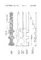
- FIG. 3is a set of waveform diagrams occuring at various points in the circuit of FIG. 2;
- FIG. 4is a schematic diagram of a preferred embodiment of the electronic circuits shown in FIG. 2.
- Capacitive pad 10may be made into a quilt cover or a mattress pad to be used over an existing mattress, or may be mounted integral with the mattress. In a typical use of the capacitance pad 10, it is placed on the top surface of a crib mattress and a conventional sheet or mattress cover installed over the pad 10. Leads 11 and 12 are preferably connected to a shielded cable 17 for connection to the electronic detector portion of the invention. Turning now to FIG. 2, a simplified block diagram of the electronic detection portion of my apnea monitor is shown. Capacitance pad 10 is shown with the guard shield foil 16 represented by the dashed lines and the grid array pattern 20 indicated by the solid lines.
- guard shield 16is connected to the output of voltage follower 27 by lead 11, there is essentially no potential therebetween and guard shield 16 serves effectively to prevent any objects on the backside of pad 10 from affecting the net capacitance thereof.
- Amplifier 30is coupled to comparator 32 which has an adjustable threshold. This threshold is adjusted with no signal from capacitance pad 10 to produce a HIGH at the output of comparator 32 as indicated on line B. During normal breathing, the output of amplifier 30 will drive the input to comparator 32 below the threshold level causing the output to go LOW. Thus, a negative going pulse will be produced for each signal produced by breathing movement.
- the output of comparator 32drives RC circuit 34. When the output of comparator 32 goes HIGH, it will charge capacitor C through resistor R as indicated on line E at 58. The time constant of the RC circuit is selected such that during a normal respiration cycle, C will charge to only a fraction of the charging voltage.
- RC circuit 34The values of RC circuit 34 are selected such that the alarm occurs early enough to permit a person monitoring to reach the infant and to assist it in restarting of breathing before physiological damage can occur. For example, a 15-20 second period is typical. SCR circuit 42 operates from a dc voltage supply V and therefore must be manually reset to turn off the alarm 44. An early warning of the onset of an apnea episode is also indicated by cessation of the flashing of the LED of event indicator 38.
- FIG. 4I show a preferred schematic diagram of the apnea monitoring system of FIG. 2 which utilizes discrete components for explanatory purposes.
- a regulated power supply 52is used having a nickel cadmium battery 41 and voltage regulator circuit 43 which produces two output voltages +V cc and +1/2V cc .
- the chargermaintains battery 41 at full charge at all times with battery 41 serving as an emergency power supply during occasional power outages.
- Preamp 24may utilize a type TLO64 operational amplifier.
- a 60 Hz notch filter 26is formed by resistors R1, R2 and R3 and capacitor C1, C2 and C3 in a bridged-T connection.
- Comparator 40may use a type TLO64 op amp and has a threshold set by the values of resistors R17 and R18. As described with reference to line E of FIG. 3, the absence of inputs to comparator 32 will cause the voltage across capacitor C to increase to the point that the threshold of comparator 40 is reached. This produces a high at the output of comparator 40, triggering SCR 42.
- SCR 42may be a General Electric type C103. Since SCR 42 has its anode voltage supplied from the dc voltage +V cc , it will conduct continuously after triggering and will energize a Sonalert sound alarm 45 and LED visual alarm 47. The alarm elements may be, of course, located in another room from the infant being monitored or may be a local alarm as desired.
- 50 kHz oscillator 46may be implemented by a type TLO64 integrated circuit connected to produce square waves at about 50 Hz.
- Zeners Z 1 and Z 2serve to place a short circuit on supply voltage V cc in the event that a line connected battery charger developed a leakage between the power line and the monitor circuit. Thus, a fuse in the charger circuit or low current diodes would blow, isolating the circuit from the power line.
Landscapes
- Health & Medical Sciences (AREA)
- Life Sciences & Earth Sciences (AREA)
- Physics & Mathematics (AREA)
- Biophysics (AREA)
- Heart & Thoracic Surgery (AREA)
- General Health & Medical Sciences (AREA)
- Physiology (AREA)
- General Physics & Mathematics (AREA)
- Pathology (AREA)
- Gerontology & Geriatric Medicine (AREA)
- Business, Economics & Management (AREA)
- Emergency Management (AREA)
- Cardiology (AREA)
- Physical Education & Sports Medicine (AREA)
- Biomedical Technology (AREA)
- Oral & Maxillofacial Surgery (AREA)
- Pulmonology (AREA)
- Engineering & Computer Science (AREA)
- Dentistry (AREA)
- Medical Informatics (AREA)
- Molecular Biology (AREA)
- Surgery (AREA)
- Animal Behavior & Ethology (AREA)
- Public Health (AREA)
- Veterinary Medicine (AREA)
- Measurement Of The Respiration, Hearing Ability, Form, And Blood Characteristics Of Living Organisms (AREA)
Abstract
Description
______________________________________ Ohms Ohms ______________________________________ R.sub.1 10M R.sub.18 10M C.sub.7 0.01 uf R.sub.2 10M R.sub.19 10k C.sub.8 0.47 uf R.sub.3 5M R.sub.20 3.9k C.sub.9 0.001 uf R.sub.4 10M R.sub.21 10M C.sub.10 47 pf R.sub.5 220k R.sub.22 10k C.sub.11 0.01 uf R.sub.6 220k R.sub.23 1k C.sub.12 0.01 uf R.sub.7 10M R.sub.24 220k C.sub.13 0.01 uf R.sub.8 10M R.sub.25 220k C.sub.14 270 pf R.sub.9 60k R.sub.26 220k R.sub.10 100k R.sub.27 100k T.sub.1 2N2906 R.sub.28 100K R.sub.11 10M C 0.47 uf T.sub.2 2N3904 R.sub.12 10k C.sub.1 540 pf R.sub.13 10M C.sub.2 270 pf Z.sub.1 9.1v. R.sub.14 1M C.sub.3 270 pf Z.sub.2 9.1v. R.sub.15 10k C.sub.4 0.1 uf R.sub.16 10k C.sub.5 0.1 uf R.sub.17 1M C.sub.6 0.02 uf ______________________________________
Claims (7)
Priority Applications (1)
| Application Number | Priority Date | Filing Date | Title |
|---|---|---|---|
| US06/377,703US4474185A (en) | 1982-05-12 | 1982-05-12 | Body movement detector |
Applications Claiming Priority (1)
| Application Number | Priority Date | Filing Date | Title |
|---|---|---|---|
| US06/377,703US4474185A (en) | 1982-05-12 | 1982-05-12 | Body movement detector |
Publications (1)
| Publication Number | Publication Date |
|---|---|
| US4474185Atrue US4474185A (en) | 1984-10-02 |
Family
ID=23490199
Family Applications (1)
| Application Number | Title | Priority Date | Filing Date |
|---|---|---|---|
| US06/377,703Expired - LifetimeUS4474185A (en) | 1982-05-12 | 1982-05-12 | Body movement detector |
Country Status (1)
| Country | Link |
|---|---|
| US (1) | US4474185A (en) |
Cited By (56)
| Publication number | Priority date | Publication date | Assignee | Title |
|---|---|---|---|---|
| US4648407A (en)* | 1985-07-08 | 1987-03-10 | Respitrace Corporation | Method for detecting and differentiating central and obstructive apneas in newborns |
| EP0222484A2 (en) | 1985-10-31 | 1987-05-20 | U.T. Medical Manufacturing, Inc. | Movement monitor for cardio-pulmonary and other activity |
| US4686999A (en)* | 1985-04-10 | 1987-08-18 | Tri Fund Research Corporation | Multi-channel ventilation monitor and method |
| US4694836A (en)* | 1984-12-21 | 1987-09-22 | U.S. Philips Corporation | MRI tomography apparatus for generating a motion signal |
| EP0205931A3 (en)* | 1985-05-23 | 1987-11-11 | Heinrich Prof. Dr. Ing. Reents | Device for measuring vital functions of a human, in particular of an infant |
| US4712560A (en)* | 1985-08-09 | 1987-12-15 | General Electric Company | Apparatus and method of acquiring physiological gating signals for magnetic resonance imaging of moving objects |
| US4971065A (en)* | 1985-02-11 | 1990-11-20 | Pearce Stephen D | Transducer for detecting apnea |
| FR2678095A1 (en)* | 1991-06-19 | 1992-12-24 | Kientz Jean Marie | Capacitive invalid call device |
| WO1995000368A1 (en)* | 1993-06-22 | 1995-01-05 | Vos Verkehrs-Optimierungs-Systeme Gmbh & Co. Kg | Device for detecting the presence of persons on seats |
| WO1996036279A1 (en)* | 1995-05-19 | 1996-11-21 | Somed Pty. Limited | Device for detecting and recording snoring |
| US5598042A (en)* | 1993-09-22 | 1997-01-28 | The Watt Stopper | Moveable desktop load controller |
| WO1997003608A1 (en)* | 1995-07-14 | 1997-02-06 | Tobias Baeuerle & Söhne Feinwerktechnik Gmbh | Device for measuring respiratory capacity |
| US5793291A (en)* | 1996-05-13 | 1998-08-11 | Thornton; Carolyn M. | Child alert system for automobiles |
| US5808552A (en)* | 1996-11-25 | 1998-09-15 | Hill-Rom, Inc. | Patient detection system for a patient-support device |
| EP0778003A3 (en)* | 1990-03-09 | 1998-09-30 | Matsushita Electric Industrial Co., Ltd. | Presence detecting apparatus |
| AU698120B2 (en)* | 1995-05-19 | 1998-10-22 | Somed Pty Limited | Device for detecting and recording snoring |
| WO1999004691A1 (en)* | 1997-07-23 | 1999-02-04 | Sensitive Technologies, Llc | Respiration and movement monitoring system |
| WO1999005476A1 (en)* | 1997-07-23 | 1999-02-04 | Teodorescu Horia Nicolai | Position and movement resonant sensor |
| US6011477A (en)* | 1997-07-23 | 2000-01-04 | Sensitive Technologies, Llc | Respiration and movement monitoring system |
| US6025782A (en)* | 1996-09-04 | 2000-02-15 | Newham; Paul | Device for monitoring the presence of a person using proximity induced dielectric shift sensing |
| US6067019A (en)* | 1996-11-25 | 2000-05-23 | Hill-Rom, Inc. | Bed exit detection apparatus |
| US6105440A (en)* | 1999-03-16 | 2000-08-22 | Research Triangle Institute | Portable air sampling systems including non-intrusive activity monitor and methods of using same |
| US6133837A (en)* | 1999-03-05 | 2000-10-17 | Hill-Rom, Inc. | Patient position system and method for a support surface |
| US6254551B1 (en) | 1997-02-05 | 2001-07-03 | Instrumentarium Corp. | Apparatus for monitoring a mechanically transmitted signal based on the organs or vital functions and for processing the results |
| US6375621B1 (en) | 1987-03-06 | 2002-04-23 | Ocean Laboratories, Inc. | Passive apnea monitor |
| US6662032B1 (en) | 1999-07-06 | 2003-12-09 | Intercure Ltd. | Interventive-diagnostic device |
| US20040116784A1 (en)* | 2002-12-13 | 2004-06-17 | Intercure Ltd. | Apparatus and method for beneficial modification of biorhythmic activity |
| US6778090B2 (en) | 1996-09-04 | 2004-08-17 | Paul Newham | Modular system for monitoring the presence of a person using a variety of sensing devices |
| US6984207B1 (en) | 1999-09-14 | 2006-01-10 | Hoana Medical, Inc. | Passive physiological monitoring (P2M) system |
| EP1619521A1 (en)* | 2004-07-22 | 2006-01-25 | IEE INTERNATIONAL ELECTRONICS & ENGINEERING S.A. | Capacitive transmitter electrode |
| US20060224089A1 (en)* | 2005-03-29 | 2006-10-05 | Agency For Science, Technology And Research | Method and apparatus for monitoring sleep behaviour |
| US20070075986A1 (en)* | 2005-10-05 | 2007-04-05 | Holtek Semiconductor Inc. | Proximity sensing device and sensing method thereof |
| US7253366B2 (en) | 2004-08-09 | 2007-08-07 | Hill-Rom Services, Inc. | Exit alarm for a hospital bed triggered by individual load cell weight readings exceeding a predetermined threshold |
| WO2007096573A1 (en)* | 2005-06-27 | 2007-08-30 | Ensco 619 Ltd. | Sensing body functions |
| US20080208063A1 (en)* | 2005-06-07 | 2008-08-28 | Koninklijke Philips Electronics N. V. | Patient Monitoring System and Method |
| US20100039269A1 (en)* | 2008-08-13 | 2010-02-18 | Paul Newham | Modular Systems for Monitoring the Presence of a Person Using a Variety of Sensing Devices |
| US7666151B2 (en) | 2002-11-20 | 2010-02-23 | Hoana Medical, Inc. | Devices and methods for passive patient monitoring |
| US20100109684A1 (en)* | 2007-03-19 | 2010-05-06 | Arthur Koblasz | Fluid Detecting Mattress Cover and Monitoring System |
| US20100283539A1 (en)* | 2009-04-30 | 2010-11-11 | Hioki Denki Kabushiki Kaisha | Voltage detection device |
| US20100308846A1 (en)* | 2009-06-05 | 2010-12-09 | Gilles Camus | Pressure sensor comprising a capacitive cell and support device comprising said sensor |
| US20110040201A1 (en)* | 2006-03-29 | 2011-02-17 | Yanchuan Pu | Periodic Disordered Breathing Detection |
| US20110144455A1 (en)* | 2007-08-31 | 2011-06-16 | Bam Labs, Inc. | Systems and methods for monitoring a subject at rest |
| US8102270B2 (en) | 2008-04-25 | 2012-01-24 | Kap Medical | Patient position apparatus and method |
| US20120053471A1 (en)* | 2009-05-18 | 2012-03-01 | Koninklijke Philips Electronics N.V. | Heart rate measuring device |
| US8717181B2 (en) | 2010-07-29 | 2014-05-06 | Hill-Rom Services, Inc. | Bed exit alert silence with automatic re-enable |
| US9351892B2 (en) | 2008-04-25 | 2016-05-31 | Kap Medical | Percussion therapy system, apparatus and method |
| JP2017127619A (en)* | 2016-01-15 | 2017-07-27 | ユースエンジニアリング株式会社 | Biological information detection apparatus and biological information detection method |
| US10292605B2 (en) | 2012-11-15 | 2019-05-21 | Hill-Rom Services, Inc. | Bed load cell based physiological sensing systems and methods |
| US20190388039A1 (en)* | 2009-10-15 | 2019-12-26 | Masimo Corporation | Bidirectional physiological information display |
| US10576355B2 (en) | 2002-08-09 | 2020-03-03 | 2Breathe Technologies Ltd. | Generalized metronome for modification of biorhythmic activity |
| CN114452012A (en)* | 2022-04-12 | 2022-05-10 | 浙江伽奈维医疗科技有限公司 | Puncture operation respiration amplitude detection device and method thereof |
| US11844605B2 (en) | 2016-11-10 | 2023-12-19 | The Research Foundation For Suny | System, method and biomarkers for airway obstruction |
| US11992361B2 (en) | 2012-09-20 | 2024-05-28 | Masimo Corporation | Acoustic patient sensor coupler |
| US11998362B2 (en) | 2009-10-15 | 2024-06-04 | Masimo Corporation | Acoustic respiratory monitoring sensor having multiple sensing elements |
| US12016721B2 (en) | 2013-10-11 | 2024-06-25 | Masimo Corporation | Acoustic sensor with attachment portion |
| US12232905B2 (en) | 2008-12-30 | 2025-02-25 | Masimo Corporation | Acoustic sensor assembly |
Citations (3)
| Publication number | Priority date | Publication date | Assignee | Title |
|---|---|---|---|---|
| US3973208A (en)* | 1975-02-14 | 1976-08-03 | Dovey Manufacturing Company | Capacitor detector device |
| US3991746A (en)* | 1975-03-31 | 1976-11-16 | Medical R & D, Limited | Patient monitoring system and method |
| US4381788A (en)* | 1981-02-27 | 1983-05-03 | Douglas David W | Method and apparatus for detecting apnea |
- 1982
- 1982-05-12USUS06/377,703patent/US4474185A/ennot_activeExpired - Lifetime
Patent Citations (3)
| Publication number | Priority date | Publication date | Assignee | Title |
|---|---|---|---|---|
| US3973208A (en)* | 1975-02-14 | 1976-08-03 | Dovey Manufacturing Company | Capacitor detector device |
| US3991746A (en)* | 1975-03-31 | 1976-11-16 | Medical R & D, Limited | Patient monitoring system and method |
| US4381788A (en)* | 1981-02-27 | 1983-05-03 | Douglas David W | Method and apparatus for detecting apnea |
Cited By (84)
| Publication number | Priority date | Publication date | Assignee | Title |
|---|---|---|---|---|
| US4694836A (en)* | 1984-12-21 | 1987-09-22 | U.S. Philips Corporation | MRI tomography apparatus for generating a motion signal |
| US4971065A (en)* | 1985-02-11 | 1990-11-20 | Pearce Stephen D | Transducer for detecting apnea |
| US4686999A (en)* | 1985-04-10 | 1987-08-18 | Tri Fund Research Corporation | Multi-channel ventilation monitor and method |
| EP0205931A3 (en)* | 1985-05-23 | 1987-11-11 | Heinrich Prof. Dr. Ing. Reents | Device for measuring vital functions of a human, in particular of an infant |
| US4895160A (en)* | 1985-05-23 | 1990-01-23 | Heinrich Reents | Apparatus for measuring the life functions of a human being, particularly an infant |
| US4648407A (en)* | 1985-07-08 | 1987-03-10 | Respitrace Corporation | Method for detecting and differentiating central and obstructive apneas in newborns |
| US4712560A (en)* | 1985-08-09 | 1987-12-15 | General Electric Company | Apparatus and method of acquiring physiological gating signals for magnetic resonance imaging of moving objects |
| EP0222484A3 (en)* | 1985-10-31 | 1988-08-03 | Diamond Research Group Inc. | Movement monitor for cardio-pulmonary and other activity |
| EP0222484A2 (en) | 1985-10-31 | 1987-05-20 | U.T. Medical Manufacturing, Inc. | Movement monitor for cardio-pulmonary and other activity |
| US6375621B1 (en) | 1987-03-06 | 2002-04-23 | Ocean Laboratories, Inc. | Passive apnea monitor |
| EP0778003A3 (en)* | 1990-03-09 | 1998-09-30 | Matsushita Electric Industrial Co., Ltd. | Presence detecting apparatus |
| US5902255A (en)* | 1990-03-09 | 1999-05-11 | Matsushita Electric Industrial Co., Ltd. | Human monitoring device |
| FR2678095A1 (en)* | 1991-06-19 | 1992-12-24 | Kientz Jean Marie | Capacitive invalid call device |
| WO1995000368A1 (en)* | 1993-06-22 | 1995-01-05 | Vos Verkehrs-Optimierungs-Systeme Gmbh & Co. Kg | Device for detecting the presence of persons on seats |
| US5724024A (en)* | 1993-06-22 | 1998-03-03 | Vos Verkehrs-Optimierungs-Systems Gmbh & Co. | Device for detecting the presence of persons on seats |
| AU694437B2 (en)* | 1993-06-22 | 1998-07-23 | Vos Verkehrs-Optimierungs-Systeme Gmbh & Co. Kg | Device for detecting the presence of persons on seats |
| US5598042A (en)* | 1993-09-22 | 1997-01-28 | The Watt Stopper | Moveable desktop load controller |
| WO1996036279A1 (en)* | 1995-05-19 | 1996-11-21 | Somed Pty. Limited | Device for detecting and recording snoring |
| AU698120B2 (en)* | 1995-05-19 | 1998-10-22 | Somed Pty Limited | Device for detecting and recording snoring |
| WO1997003608A1 (en)* | 1995-07-14 | 1997-02-06 | Tobias Baeuerle & Söhne Feinwerktechnik Gmbh | Device for measuring respiratory capacity |
| US5793291A (en)* | 1996-05-13 | 1998-08-11 | Thornton; Carolyn M. | Child alert system for automobiles |
| US6778090B2 (en) | 1996-09-04 | 2004-08-17 | Paul Newham | Modular system for monitoring the presence of a person using a variety of sensing devices |
| US6297738B1 (en) | 1996-09-04 | 2001-10-02 | Paul Newham | Modular system for monitoring the presence of a person using a variety of sensing devices |
| US6025782A (en)* | 1996-09-04 | 2000-02-15 | Newham; Paul | Device for monitoring the presence of a person using proximity induced dielectric shift sensing |
| US5808552A (en)* | 1996-11-25 | 1998-09-15 | Hill-Rom, Inc. | Patient detection system for a patient-support device |
| US6067019A (en)* | 1996-11-25 | 2000-05-23 | Hill-Rom, Inc. | Bed exit detection apparatus |
| US6254551B1 (en) | 1997-02-05 | 2001-07-03 | Instrumentarium Corp. | Apparatus for monitoring a mechanically transmitted signal based on the organs or vital functions and for processing the results |
| US6011477A (en)* | 1997-07-23 | 2000-01-04 | Sensitive Technologies, Llc | Respiration and movement monitoring system |
| WO1999004691A1 (en)* | 1997-07-23 | 1999-02-04 | Sensitive Technologies, Llc | Respiration and movement monitoring system |
| US5986549A (en)* | 1997-07-23 | 1999-11-16 | Teodorescu; Horia-Nicolai | Position and movement reasonant sensor |
| WO1999005476A1 (en)* | 1997-07-23 | 1999-02-04 | Teodorescu Horia Nicolai | Position and movement resonant sensor |
| US6133837A (en)* | 1999-03-05 | 2000-10-17 | Hill-Rom, Inc. | Patient position system and method for a support surface |
| US6105440A (en)* | 1999-03-16 | 2000-08-22 | Research Triangle Institute | Portable air sampling systems including non-intrusive activity monitor and methods of using same |
| US20100037753A1 (en)* | 1999-07-06 | 2010-02-18 | Naphtali Wagner | Interventive-diagnostic device |
| US20040077934A1 (en)* | 1999-07-06 | 2004-04-22 | Intercure Ltd. | Interventive-diagnostic device |
| US10314535B2 (en) | 1999-07-06 | 2019-06-11 | 2Breathe Technologies Ltd. | Interventive-diagnostic device |
| US9446302B2 (en) | 1999-07-06 | 2016-09-20 | 2Breathe Technologies Ltd. | Interventive-diagnostic device |
| US6662032B1 (en) | 1999-07-06 | 2003-12-09 | Intercure Ltd. | Interventive-diagnostic device |
| US8658878B2 (en) | 1999-07-06 | 2014-02-25 | Intercure Ltd. | Interventive diagnostic device |
| US8183453B2 (en) | 1999-07-06 | 2012-05-22 | Intercure Ltd. | Interventive-diagnostic device |
| US7717858B2 (en) | 1999-07-06 | 2010-05-18 | Intercure Ltd. | Interventive-diagnostic device |
| US6984207B1 (en) | 1999-09-14 | 2006-01-10 | Hoana Medical, Inc. | Passive physiological monitoring (P2M) system |
| US20060063982A1 (en)* | 1999-09-14 | 2006-03-23 | Hoana Medical, Inc. | Passive physiological monitoring (P2M) system |
| US10576355B2 (en) | 2002-08-09 | 2020-03-03 | 2Breathe Technologies Ltd. | Generalized metronome for modification of biorhythmic activity |
| US7666151B2 (en) | 2002-11-20 | 2010-02-23 | Hoana Medical, Inc. | Devices and methods for passive patient monitoring |
| US8672852B2 (en) | 2002-12-13 | 2014-03-18 | Intercure Ltd. | Apparatus and method for beneficial modification of biorhythmic activity |
| US10531827B2 (en) | 2002-12-13 | 2020-01-14 | 2Breathe Technologies Ltd. | Apparatus and method for beneficial modification of biorhythmic activity |
| US20040116784A1 (en)* | 2002-12-13 | 2004-06-17 | Intercure Ltd. | Apparatus and method for beneficial modification of biorhythmic activity |
| WO2006008246A1 (en)* | 2004-07-22 | 2006-01-26 | Iee International Electronics & Engineering S.A. | Capacitive transmitter electrode |
| EP1619521A1 (en)* | 2004-07-22 | 2006-01-25 | IEE INTERNATIONAL ELECTRONICS & ENGINEERING S.A. | Capacitive transmitter electrode |
| US20080067793A1 (en)* | 2004-07-22 | 2008-03-20 | Harald Clos | Capacitive Transmitter Electrode |
| US7437787B2 (en) | 2004-08-09 | 2008-10-21 | Hill-Rom Services, Inc. | Load-cell based hospital bed control |
| US7253366B2 (en) | 2004-08-09 | 2007-08-07 | Hill-Rom Services, Inc. | Exit alarm for a hospital bed triggered by individual load cell weight readings exceeding a predetermined threshold |
| US20060224089A1 (en)* | 2005-03-29 | 2006-10-05 | Agency For Science, Technology And Research | Method and apparatus for monitoring sleep behaviour |
| US20080208063A1 (en)* | 2005-06-07 | 2008-08-28 | Koninklijke Philips Electronics N. V. | Patient Monitoring System and Method |
| US9788791B2 (en)* | 2005-06-07 | 2017-10-17 | Koninklijke Philips N.V. | Patient monitoring system and method |
| WO2007096573A1 (en)* | 2005-06-27 | 2007-08-30 | Ensco 619 Ltd. | Sensing body functions |
| US20080275328A1 (en)* | 2005-06-27 | 2008-11-06 | David Paul Jones | Sensing body functions |
| US20070075986A1 (en)* | 2005-10-05 | 2007-04-05 | Holtek Semiconductor Inc. | Proximity sensing device and sensing method thereof |
| US20110040201A1 (en)* | 2006-03-29 | 2011-02-17 | Yanchuan Pu | Periodic Disordered Breathing Detection |
| US20100109684A1 (en)* | 2007-03-19 | 2010-05-06 | Arthur Koblasz | Fluid Detecting Mattress Cover and Monitoring System |
| US8169329B2 (en)* | 2007-03-19 | 2012-05-01 | Arthur Koblasz | Fluid detecting mattress cover and monitoring system |
| US20110144455A1 (en)* | 2007-08-31 | 2011-06-16 | Bam Labs, Inc. | Systems and methods for monitoring a subject at rest |
| US8102270B2 (en) | 2008-04-25 | 2012-01-24 | Kap Medical | Patient position apparatus and method |
| US9351892B2 (en) | 2008-04-25 | 2016-05-31 | Kap Medical | Percussion therapy system, apparatus and method |
| US7940187B2 (en) | 2008-08-13 | 2011-05-10 | Paul Newham | Modular systems for monitoring the presence of a person using a variety of sensing devices |
| US20100039269A1 (en)* | 2008-08-13 | 2010-02-18 | Paul Newham | Modular Systems for Monitoring the Presence of a Person Using a Variety of Sensing Devices |
| US12232905B2 (en) | 2008-12-30 | 2025-02-25 | Masimo Corporation | Acoustic sensor assembly |
| US20100283539A1 (en)* | 2009-04-30 | 2010-11-11 | Hioki Denki Kabushiki Kaisha | Voltage detection device |
| US9445750B2 (en)* | 2009-05-18 | 2016-09-20 | Koninklijke Philips N.V. | Heart rate measuring device |
| US20120053471A1 (en)* | 2009-05-18 | 2012-03-01 | Koninklijke Philips Electronics N.V. | Heart rate measuring device |
| US8598893B2 (en) | 2009-06-05 | 2013-12-03 | Hill-Rom Industries Sa | Pressure sensor comprising a capacitive cell and support device comprising said sensor |
| US20100308846A1 (en)* | 2009-06-05 | 2010-12-09 | Gilles Camus | Pressure sensor comprising a capacitive cell and support device comprising said sensor |
| US20190388039A1 (en)* | 2009-10-15 | 2019-12-26 | Masimo Corporation | Bidirectional physiological information display |
| US11998362B2 (en) | 2009-10-15 | 2024-06-04 | Masimo Corporation | Acoustic respiratory monitoring sensor having multiple sensing elements |
| US12257081B2 (en)* | 2009-10-15 | 2025-03-25 | Masimo Corporation | Bidirectional physiological information display |
| US8717181B2 (en) | 2010-07-29 | 2014-05-06 | Hill-Rom Services, Inc. | Bed exit alert silence with automatic re-enable |
| US11992361B2 (en) | 2012-09-20 | 2024-05-28 | Masimo Corporation | Acoustic patient sensor coupler |
| US10292605B2 (en) | 2012-11-15 | 2019-05-21 | Hill-Rom Services, Inc. | Bed load cell based physiological sensing systems and methods |
| US12016721B2 (en) | 2013-10-11 | 2024-06-25 | Masimo Corporation | Acoustic sensor with attachment portion |
| JP2017127619A (en)* | 2016-01-15 | 2017-07-27 | ユースエンジニアリング株式会社 | Biological information detection apparatus and biological information detection method |
| US11844605B2 (en) | 2016-11-10 | 2023-12-19 | The Research Foundation For Suny | System, method and biomarkers for airway obstruction |
| CN114452012A (en)* | 2022-04-12 | 2022-05-10 | 浙江伽奈维医疗科技有限公司 | Puncture operation respiration amplitude detection device and method thereof |
| CN114452012B (en)* | 2022-04-12 | 2022-07-08 | 浙江伽奈维医疗科技有限公司 | Puncture operation breathing amplitude detection device and method thereof |
Similar Documents
| Publication | Publication Date | Title |
|---|---|---|
| US4474185A (en) | Body movement detector | |
| US4757825A (en) | Cardio-pulmonary activity monitor | |
| US4033332A (en) | Activity and respiration monitor | |
| US3926177A (en) | Activity and respiration monitor | |
| US4438771A (en) | Passive contactless monitor for detecting cessation of cardiopulmonary | |
| US4971065A (en) | Transducer for detecting apnea | |
| US3760794A (en) | Respiration monitoring apparatus and method | |
| US5353012A (en) | Bed position and activity sensing apparatus | |
| US4895160A (en) | Apparatus for measuring the life functions of a human being, particularly an infant | |
| US4494553A (en) | Vital signs monitor | |
| EP1017315B1 (en) | Respiration and movement monitoring system | |
| US6064910A (en) | Respirator rate/respiration depth detector and device for monitoring respiratory activity employing same | |
| US4197856A (en) | Ultrasonic respiration/convulsion monitoring apparatus and method for its use | |
| US4350166A (en) | Apnea detector | |
| US4827943A (en) | Portable, multi-channel, physiological data monitoring system | |
| US3996922A (en) | Flexible force responsive transducer | |
| EP0073240A1 (en) | Method and apparatus for detecting apnea | |
| US3898981A (en) | Respiration monitoring apparatus | |
| JP2959376B2 (en) | Monitoring device | |
| SE9401959D0 (en) | Method and apparatus for assessing wakefulness and drowsiness at various stages between wakefulness and sleep in a way that is not monitored non-interfering | |
| US5069221A (en) | Displacement sensor and medical apparatus | |
| WO1999004691A1 (en) | Respiration and movement monitoring system | |
| US20180078180A1 (en) | Occupancy monitoring device | |
| JP2000271103A (en) | Apnea detecting apparatus | |
| US5335666A (en) | Medical monitor with input regulation |
Legal Events
| Date | Code | Title | Description |
|---|---|---|---|
| STCF | Information on status: patent grant | Free format text:PATENTED CASE | |
| AS | Assignment | Owner name:DIAMOND RSEARCH GROUP, INC., A FL CORP Free format text:ASSIGNMENT OF ASSIGNORS INTEREST.;ASSIGNOR:DIAMOND, DONALD A.;REEL/FRAME:004424/0022 Effective date:19850629 | |
| REMI | Maintenance fee reminder mailed | ||
| FPAY | Fee payment | Year of fee payment:4 | |
| SULP | Surcharge for late payment | ||
| AS | Assignment | Owner name:U.T. MEDICAL MANUFACTURING, INC., A CORP. OF FLORI Free format text:ASSIGNMENT OF ASSIGNORS INTEREST.;ASSIGNOR:DIAMOND RESEARCH GROUP, INC., A CORP. OF FLORIDA;REEL/FRAME:005441/0670 Effective date:19901108 | |
| FEPP | Fee payment procedure | Free format text:PAYOR NUMBER ASSIGNED (ORIGINAL EVENT CODE: ASPN); ENTITY STATUS OF PATENT OWNER: SMALL ENTITY | |
| REMI | Maintenance fee reminder mailed | ||
| FPAY | Fee payment | Year of fee payment:8 | |
| SULP | Surcharge for late payment | ||
| AS | Assignment | Owner name:MEDICAL SCIENCES LIMITED Free format text:LICENSE;ASSIGNOR:PERINATRONICS, INC.;REEL/FRAME:007414/0086 Effective date:19920807 | |
| FPAY | Fee payment | Year of fee payment:12 | |
| FEPP | Fee payment procedure | Free format text:PAYER NUMBER DE-ASSIGNED (ORIGINAL EVENT CODE: RMPN); ENTITY STATUS OF PATENT OWNER: SMALL ENTITY Free format text:PAYOR NUMBER ASSIGNED (ORIGINAL EVENT CODE: ASPN); ENTITY STATUS OF PATENT OWNER: SMALL ENTITY |