US4473363A - Composite plastic and metal pulley construction - Google Patents
Composite plastic and metal pulley constructionDownload PDFInfo
- Publication number
- US4473363A US4473363AUS06/294,578US29457881AUS4473363AUS 4473363 AUS4473363 AUS 4473363AUS 29457881 AUS29457881 AUS 29457881AUS 4473363 AUS4473363 AUS 4473363A
- Authority
- US
- United States
- Prior art keywords
- pulley
- plastic
- metal
- belt
- poly
- Prior art date
- Legal status (The legal status is an assumption and is not a legal conclusion. Google has not performed a legal analysis and makes no representation as to the accuracy of the status listed.)
- Expired - Lifetime
Links
Images
Classifications
- F—MECHANICAL ENGINEERING; LIGHTING; HEATING; WEAPONS; BLASTING
- F16—ENGINEERING ELEMENTS AND UNITS; GENERAL MEASURES FOR PRODUCING AND MAINTAINING EFFECTIVE FUNCTIONING OF MACHINES OR INSTALLATIONS; THERMAL INSULATION IN GENERAL
- F16H—GEARING
- F16H55/00—Elements with teeth or friction surfaces for conveying motion; Worms, pulleys or sheaves for gearing mechanisms
- F16H55/32—Friction members
- F16H55/36—Pulleys
- F16H55/48—Pulleys manufactured exclusively or in part of non-metallic material, e.g. plastics
- Y—GENERAL TAGGING OF NEW TECHNOLOGICAL DEVELOPMENTS; GENERAL TAGGING OF CROSS-SECTIONAL TECHNOLOGIES SPANNING OVER SEVERAL SECTIONS OF THE IPC; TECHNICAL SUBJECTS COVERED BY FORMER USPC CROSS-REFERENCE ART COLLECTIONS [XRACs] AND DIGESTS
- Y10—TECHNICAL SUBJECTS COVERED BY FORMER USPC
- Y10S—TECHNICAL SUBJECTS COVERED BY FORMER USPC CROSS-REFERENCE ART COLLECTIONS [XRACs] AND DIGESTS
- Y10S474/00—Endless belt power transmission systems or components
- Y10S474/902—Particular connection between rim and hub
Definitions
- the inventionrelates to V-grooved pulleys for use with the endless drive belt of a vehicle accessories drive system and particularly for the alternator drive pulley. More particularly, the invention relates to a composite pulley in which the body or hub of the pulley is formed of a flat metal disc which is bonded within a multi-V-groove belt-receiving formation formed of a molded plastic.
- These spun metal pulleysare formed with the usual single, double or triple V-shaped belt-receiving grooves in which the V-groove-forming walls are either equal in thickness or thinner than the thickness of the parent metal of the pulley wall in which the grooves are formed.
- these prior art grooveshave generally rounded crests and valleys between adjacent grooves and are adapted to receive a plurality of individual drive belts having the usual inverted trapezoidal cross-sectional configurations and not the particular cross-sectional configurations of the serpentine drive belts.
- U.S. Pat. Nos. 3,557,424, 3,651,705 and 3,696,685illustrate examples of composite plastic and metal pulleys of the type in which the outer pulley surface is formed with a series of teeth for use with a toothed belt drive.
- U.S. Pat. Nos. 3,772,928 and 3,788,155are examples of two known composite plastic metal pulleys in which the pulley is formed with a V-groove in an outer portion thereof. The plastic formation in which the V-grooves of these two known pulleys are formed use internal and external metal reinforcement to strengthen the grooves and use a considerable amount of plastic material.
- Objectives of the inventioninclude providing a new composite pulley construction having a metal, generally disc-shaped body or hub which can be die stamped easily and inexpensively from sheet metal, in which a multi-V-groove pulley formation of plastic is molded on an outer peripheral edge of the disc, in which the pulley formation is defined by a series of outwardly opening V-shaped grooves which preferably are located between a pair of enlarged, spaced belt-retaining, annular-shaped end projections, and in which the plastic supporting outer edge of the metal disc is formed with projections such as scallops to prevent rotation between the plastic pulley groove formation and the disc.
- Another objectiveis to provide such a composite pulley which is less expensive than the heretofore all-metal pulleys, which has sufficient strength at the location of the belt-receiving grooves without internal metal reinforcing members within the V-groove-forming plastic, and which provides better belt life and better pulley groove tolerances than believed possible with prior all-metal pulley constructions.
- Another objectiveis to provide such a composite pulley which is lighter in weight than all-metal pulleys without sacrificing the required strength and rigidity, in which the pulley groove formation can be molded easily on the metal disc during the molding operation, in which the pulley forming plastic material is less susceptible to rust and corrosion than prior all-metal pulleys, and in which the plastic has a self-lubricating effect which provides a better running relationship between the belt and pulley grooves to increase belt life and force transfer efficiency.
- Another objective of the inventionis to provide such a composite pulley for use as the alternator drive pulley, which pulley is smaller than the usual pulleys used for the other vehicle accessories and which has a relatively small diameter with respect to the axial length of the belt-receiving groove formation, in which the metal disc which provides the mounting means for the plastic V-groove pulley formation is formed with a central hole or opening coaxial with the axis of the hollow cylindrical bore of the plastic belt-receiving groove formation, in which the metal disc is mounted between the open ends of the hollow bore of the pulley groove formation, and in which the diameter of one of said open ends is sufficiently larger than the central opening of the metal disc to enable a tool to be inserted therein for clamping a nut against the metal disc for mounting the pulley on an alternator shaft.
- Another objectiveis to provide projections on the outer periphery of the metal disc, such as radially extending scallops, to assist the bonding of the plastic to the metal to prevent rotation between the metal disc and plastic pulley formation.
- a still further objectiveis to provide such a composite pulley which achieves the stated objectives effectively and efficiently, and which solves problems and satisfies needs existing in the multi-V-groove belt drive art and particularly in forming the smaller alternator drive pulleys.
- multi-V-groove composite plastic and metal pulley constructionincluding a hollow, cylindrical-shaped multi-V-groove pulley formation formed of plastic having a series of outwardly opening V-shaped grooves and an axially extending central bore formed therein; and a generally flat metal disc located within the central bore of the plastic pulley formation and extending perpendicular with respect to the axis of said central bore, said disc being formed with a central opening and having an outer edge formed with projections, said projections being embedded within the plastic of the pulley formation with the disc opening being concentric with the central bore thereof for mounting the pulley construction on the shaft of a vehicle accessory.
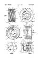
- FIG. 1is a side elevational view of the improved composite plastic pulley construction
- FIG. 2is a right-hand end elevational view of the pulley of FIG. 1;
- FIG. 3is a left-hand end elevational view of the pulley of FIG. 1;
- FIG. 4is a sectional view taken on line 4--4, FIG. 2;
- FIG. 5is a plan view of the metal disc-shaped member of the improved pulley prior to being bonded within the plastic V-groove formation;
- FIG. 6is a fragmentary view, portions of which are in section, showing the mounting of the improved composite pulley on a shaft of an alternator.
- Pulley 1includes as its main components a generally disc-shaped metal member 2 and a multi-V-groove formation formed of plastic, indicated generally at 3.
- Disc 2which is shown particularly in FIG. 5, has a generally flat configuration with parallel surfaces 4 and 5 and an outer peripheral edge 6. Edge 6 is formed with a plurality of radially extending projections, such as scallops 7.
- Disc 2preferably is stamped from sheet steel such as 1010 or 1018 low carbon steel, and requires no machining, casting or other expensive manufacturing operation.
- a hole or opening 8is formed in the center of disc 2, preferably during the stamping operation. The edges of hole 8 may be beveled at 9.
- the composite pulley 1consists of two pieces, the metal hub member 2 shown in FIG. 5 and the plastic body 3.
- the metal hub member 2has an unbroken peripheral edge shaped with the scallops 7 as shown in FIG. 5.
- the plastic material surfaces of the outwardly opening V-shaped grooves 14form the outer annular pulley surface.
- Pulley formation 3is supported on and molded to outer peripheral edge 6 of disc 2. Scallop projections 7 extend radially into the plastic of formation 3 and prevent relative rotation of disc 2 with respect to pulley formation 3.
- Pulley formation 3includes a pair of spaced inner and outer belt-retaining annular flanges or end projections 11 and 12, which are formed integrally with a series of intervening outwardly opening V-shaped grooves 14.
- V-grooves 14are formed between spaced pairs of inverted outwardly extending V-shaped projections 15 which are formed of plastic and project outwardly from a common integral base 16. The two endmost V-grooves 14 are formed by the endmost V-shaped projections 15 and the adjacent belt-retaining projections 11 and 12.
- Belt-retaining projections 11 and 12are formed integrally with base 16 and are of the same plastic material as are V-shaped projections 15. Retaining projections 11 and 12 preferably extend radially outwardly beyond the crests of projections 15 and prevent excess sideways movement of the belt with respect to multi-V-groove formation 5.
- the outer ends 18 and 19 of belt-retaining projections 11 and 12, respectively,are generally rounded to eliminate sharp edges which could possibly contact the moving drive belt damaging the same or injuring a mechanic or other individual performing maintenance on the vehicle engine.
- Pulley formation 3has generally hollow cylindrical configuration with a smooth inner bore 20 which extends completely through the formation.
- an annular end portion 21is formed in bore 20 with a smaller diameter. This provides increased strength due to the proximity of disc 2 adjacent the inner open end 22 of formation 3.
- Bore 20also terminates in an outer open end 23.
- disc 2is shown molded within pulley groove formation 3 closely adjacent the inner open end 22 thereof, it can be located at various locations axially along bore 20 without affecting the concept of the invention.
- the particular location of disc 2is varied to meet the individual vehicle manufacturer's requirements, depending on the alternator construction on which pulley 1 will be mounted.
- the particular plastic from which multi-V-groove formation 3 is formedmay vary depending upon the various physical characteristics desired in the final pulley product. Broadly, the plastic will be a high temperature, reinforced thermoplastic or thermosetting plastic.
- Two types of particular plastics which have been found suitable for use in molding formation 3are a phenolic plastic having a glass or mineral filler and sold by the Hooker Chemicals & Plastics Company of North Tonawanda, N.Y., under its trademark DUREZ, Grade No. 30645, and a phenolic plastic, glass fiber reinforced, manufactured by Rogers Corporation of Manchester, Conn., under its designation RX 862. Both of these types of plastics are high impact, heat resistant and asbestos free. Other types of plastics could be used in forming V-groove formation 3, although the above two types are believed to be quite satisfactory.
- FIG. 6shows a typical mounting installation of improved composite pulley 1 on an alternator, indicated generally at 25.
- Alternator 25includes a bearing assembly 26 located within a mounting bracket 27 for rotatably mounting alternator shaft 28.
- the outer end of shaft 28is threaded at 29.
- Pulley 1, and particularly disc 2 thereof,will be clamped tightly against the end of a cooling fan 30 and a sleeve 31 by a nut 32.
- a washer 33preferably is located between nut 32 and disc 2.
- pulley 1is relatively small in contrast to most vehicle accessory drive pulleys, the diameter of bore 20 must be sufficiently large to enable a tool to be telescopically inserted through open outer end 20 of formation 3.
- the extremely small size of pulley 1is best illustrated by the following example, which is the particular size and proportion shown in the drawing.
- the axial length of pulley groove formation 3 between the outer end faces of belt-retaining flanges 11 and 12is 1.16 inches and the diameter of end flanges 11 and 12 is 2.40 inches.
- the internal diameter of bore 20is 1.50 inches and the internal diameter of reduced bore portion 21 is 1.41 inches.
- Disc 2has a diameter of 1.57 inches, with the diameter between a diametrically opposed pair of scallops 7 being 1.67 inches.
- the diameter of shaft-receiving opening 8 of disc 2is 0.67 inches. Also, the thickness of V-groove formation 3 measured radially between bore 20 and the peaks of V-shaped projections 15 is 0.35 inches. With this configuration, the diameter of the pulley groove formation 3 is approximately twice the axial length thereof, which is appreciably different from the heretofore larger pulleys used for the other vehicle accessory drives.
- Pulley 1provides a construction which has the advantages of an all-metal pulley as well as the advantages of a plastic pulley.
- the main body portion of the pulleycan be stamped inexpensively from sheet metal by usual procedures to form disc-shaped member 2 having any desired size and configuration.
- Various projection meanscan be formed on the outer edge of the metal body whereby the plastic can be easily bonded thereto.
- the pulley grooves which are formed in plastic formation 3provide better belt life and pulley groove tolerances than possible with the all-metal pulley.
- This composite pulley constructionuses less plastic than prior composite plastic metal pulleys or all-plastic pulleys without sacrificing strength due to the particular V-groove formation thereof, and it enables a minimum of metal to be used for the disc-shaped body than in prior all-metal pulleys since additional metal is not required in an outer portion of forming the grooves. This results in both a lighter weight and less expensive pulley than prior all-metal pulleys.
- metal member 2is a washerlike generally circular pulley mounting plate which has an axial opening 8 adapted to be telescoped over and clamped by a nut 32 to the end portion of an alternator shaft 28 for mounting the pulley on the alternator, as shown in FIG. 6.
- Plate 2has flat surfaces (FIG. 4) that extend normal to the axis of its opening 8, and its generally circular peripheral edge 6 is formed with a plurality of circumferentially spaced slightly radially extending scallop projections 7.
- the plastic body 3is ringlike in shape and has a large diameter inner cylindrical surface or bore 20 (FIG. 6), as shown, and the body has an outer annular typical poly-V-groove formation or shape in cross section. The plate scallops and peripheral edge portion extend into and are embedded in the body beneath the poly-V-grooves intermediate the annular flange projections 11 and 12, closer to flange 11 than 12, as shown.
- the composite pulley constructionis simplified, provides an effective, safe, inexpensive and efficient pulley which achieves all the enumerated objectives, provides for eliminating difficulties encountered with prior pulleys, and solves problems and obtains new results in the art.
Landscapes
- Engineering & Computer Science (AREA)
- General Engineering & Computer Science (AREA)
- Manufacturing & Machinery (AREA)
- Mechanical Engineering (AREA)
- Pulleys (AREA)
Abstract
Description
The new construction in this application comprises an improvement on the device disclosed in the copending U.S. application of Applicant, Ser. No. 273,237, filed June 12, 1981 and owned by and assigned to the assignee of this application.
1. Field of the Invention
The invention relates to V-grooved pulleys for use with the endless drive belt of a vehicle accessories drive system and particularly for the alternator drive pulley. More particularly, the invention relates to a composite pulley in which the body or hub of the pulley is formed of a flat metal disc which is bonded within a multi-V-groove belt-receiving formation formed of a molded plastic.
2. Description of the Prior Art
There is a trend today in the automobile industry to operate the various vehicle accessories such as the power steering pump, air pumps, air conditioning and alternator by a single endless drive belt driven by a pulley connected to the engine crankshaft. This system is referred to as a "serpentine" drive belt system. This has resulted in the need for strong, efficient and reliable operating pulleys for driving the various vehicle accessories by their connection to the serpentine drive belt. These pulleys must have accurately formed V-grooves, dynamic pulley balance, and thick, rigid and strong areas in which the pulley grooves are formed.
Heretofore, such multi-V-grooved pulleys were formed completely of metal. A cup-shaped blank was either die stamped or roller spun from metal sheets with the V-grooves being subsequently stamped, slit or roller spun in an outer wall portion thereof. Examples of such all-metal pulleys are shown in U.S. Pat. Nos. 2,869,223, 3,908,421, 3,995,474 and 3,991,598.
These spun metal pulleys are formed with the usual single, double or triple V-shaped belt-receiving grooves in which the V-groove-forming walls are either equal in thickness or thinner than the thickness of the parent metal of the pulley wall in which the grooves are formed. Also, these prior art grooves have generally rounded crests and valleys between adjacent grooves and are adapted to receive a plurality of individual drive belts having the usual inverted trapezoidal cross-sectional configurations and not the particular cross-sectional configurations of the serpentine drive belts.
One known pulley which has been produced for use with these serpentine drive belts and which eliminates many of the problems and difficulties encountered with prior pulleys is shown in U.S. Pat. No. 3,977,264. This patent discusses the problems and difficulties that are involved in forming a satisfactory pulley construction having the required multi-V-groove belt-receiving formation in an outer portion thereof for the serpentine drive belts. Although pulleys formed by the metal-working procedure of U.S. Pat. No. 3,772,928 provide a satisfactory and efficient pulley, it is believed that a composite pulley formed of plastic and metal provides a construction which is less expensive, lighter in weight, and has strength comparable with the all-metal pulleys heretofore used.
Composite pulleys formed of plastic and metal are not new, per se. U.S. Pat. Nos. 3,557,424, 3,651,705 and 3,696,685 illustrate examples of composite plastic and metal pulleys of the type in which the outer pulley surface is formed with a series of teeth for use with a toothed belt drive. U.S. Pat. Nos. 3,772,928 and 3,788,155 are examples of two known composite plastic metal pulleys in which the pulley is formed with a V-groove in an outer portion thereof. The plastic formation in which the V-grooves of these two known pulleys are formed use internal and external metal reinforcement to strengthen the grooves and use a considerable amount of plastic material. Unbalanced pulleys could result with such prior composite constructions if the plastic reinforcing metal tabs or members are not completely uniform and symmetrical throughout the metal body. Also, formation of these tabs requires another manufacturing operation and additional equipment, thereby increasing the cost of the final pulley product. Furthermore, the V-grooves of these two pulleys are of the type having a cross-sectional configuration adapted for receiving individual drive belts having a usual inverted trapezoidal cross-sectional configuration as the heretofore all-metal belt-receiving pulleys.
The problems of forming an all-metal pulley are even greater for the alternator pulley since it is considerably smaller than the pulleys used for the other vehicle accessories. This smaller size pulley enables greater belt wrap to be obtained, and, correspondingly, achieves less slippage and improved efficiency, and obtains a higher rotational speed for increased alternator efficiency. This small size pulley makes it extremely difficult to satisfactorily and inexpensively blank and draw cups from metal sheets and form the multi-V-groove formations therein. Therefore, these smaller alternator pulleys are cast or machined, which increases considerably the cost thereof.
Accordingly, the need has existed for a multi-V-groove pulley having a generally flat, disc-shaped metal member molded within a multi-V-groove belt-receiving plastic formation which avoids the difficulties and undesirable characteristics present in prior all-metal multi-V-grooved pulleys and achieves results not obtainable with existing composite plastic metal pulleys.
Objectives of the invention include providing a new composite pulley construction having a metal, generally disc-shaped body or hub which can be die stamped easily and inexpensively from sheet metal, in which a multi-V-groove pulley formation of plastic is molded on an outer peripheral edge of the disc, in which the pulley formation is defined by a series of outwardly opening V-shaped grooves which preferably are located between a pair of enlarged, spaced belt-retaining, annular-shaped end projections, and in which the plastic supporting outer edge of the metal disc is formed with projections such as scallops to prevent rotation between the plastic pulley groove formation and the disc. Another objective is to provide such a composite pulley which is less expensive than the heretofore all-metal pulleys, which has sufficient strength at the location of the belt-receiving grooves without internal metal reinforcing members within the V-groove-forming plastic, and which provides better belt life and better pulley groove tolerances than believed possible with prior all-metal pulley constructions. Another objective is to provide such a composite pulley which is lighter in weight than all-metal pulleys without sacrificing the required strength and rigidity, in which the pulley groove formation can be molded easily on the metal disc during the molding operation, in which the pulley forming plastic material is less susceptible to rust and corrosion than prior all-metal pulleys, and in which the plastic has a self-lubricating effect which provides a better running relationship between the belt and pulley grooves to increase belt life and force transfer efficiency.
Another objective of the invention is to provide such a composite pulley for use as the alternator drive pulley, which pulley is smaller than the usual pulleys used for the other vehicle accessories and which has a relatively small diameter with respect to the axial length of the belt-receiving groove formation, in which the metal disc which provides the mounting means for the plastic V-groove pulley formation is formed with a central hole or opening coaxial with the axis of the hollow cylindrical bore of the plastic belt-receiving groove formation, in which the metal disc is mounted between the open ends of the hollow bore of the pulley groove formation, and in which the diameter of one of said open ends is sufficiently larger than the central opening of the metal disc to enable a tool to be inserted therein for clamping a nut against the metal disc for mounting the pulley on an alternator shaft. Another objective is to provide projections on the outer periphery of the metal disc, such as radially extending scallops, to assist the bonding of the plastic to the metal to prevent rotation between the metal disc and plastic pulley formation. A still further objective is to provide such a composite pulley which achieves the stated objectives effectively and efficiently, and which solves problems and satisfies needs existing in the multi-V-groove belt drive art and particularly in forming the smaller alternator drive pulleys.
These and other objectives and advantages may be obtained by the multi-V-groove composite plastic and metal pulley construction, the general nature of which may be stated as including a hollow, cylindrical-shaped multi-V-groove pulley formation formed of plastic having a series of outwardly opening V-shaped grooves and an axially extending central bore formed therein; and a generally flat metal disc located within the central bore of the plastic pulley formation and extending perpendicular with respect to the axis of said central bore, said disc being formed with a central opening and having an outer edge formed with projections, said projections being embedded within the plastic of the pulley formation with the disc opening being concentric with the central bore thereof for mounting the pulley construction on the shaft of a vehicle accessory.
A preferred embodiment of the composite pulley construction of the invention, illustrative of the best mode in which applicant has contemplated applying the principles, is set forth in the following description and shown in the drawing, and is particularly and distinctly pointed out and set forth in the appended claims.
FIG. 1 is a side elevational view of the improved composite plastic pulley construction;
FIG. 2 is a right-hand end elevational view of the pulley of FIG. 1;
FIG. 3 is a left-hand end elevational view of the pulley of FIG. 1;
FIG. 4 is a sectional view taken online 4--4, FIG. 2; FIG. 5 is a plan view of the metal disc-shaped member of the improved pulley prior to being bonded within the plastic V-groove formation; and
FIG. 6 is a fragmentary view, portions of which are in section, showing the mounting of the improved composite pulley on a shaft of an alternator.
Similar numerals refer to similar parts throughout the drawing.
The improved composite pulley construction is indicated generally at 1, and is shown in FIGS. 1-4. Pulley 1 includes as its main components a generally disc-shaped metal member 2 and a multi-V-groove formation formed of plastic, indicated generally at 3.Disc 2, which is shown particularly in FIG. 5, has a generally flat configuration withparallel surfaces peripheral edge 6.Edge 6 is formed with a plurality of radially extending projections, such asscallops 7.Disc 2 preferably is stamped from sheet steel such as 1010 or 1018 low carbon steel, and requires no machining, casting or other expensive manufacturing operation. A hole oropening 8 is formed in the center ofdisc 2, preferably during the stamping operation. The edges ofhole 8 may be beveled at 9.
Thus, the composite pulley 1 consists of two pieces, themetal hub member 2 shown in FIG. 5 and theplastic body 3. Themetal hub member 2 has an unbroken peripheral edge shaped with thescallops 7 as shown in FIG. 5. The plastic material surfaces of the outwardly opening V-shapedgrooves 14 form the outer annular pulley surface.
Belt-retainingprojections 11 and 12 are formed integrally withbase 16 and are of the same plastic material as are V-shapedprojections 15. Retainingprojections 11 and 12 preferably extend radially outwardly beyond the crests ofprojections 15 and prevent excess sideways movement of the belt with respect to multi-V-groove formation 5. The outer ends 18 and 19 of belt-retainingprojections 11 and 12, respectively, are generally rounded to eliminate sharp edges which could possibly contact the moving drive belt damaging the same or injuring a mechanic or other individual performing maintenance on the vehicle engine.
Althoughdisc 2 is shown molded withinpulley groove formation 3 closely adjacent the inneropen end 22 thereof, it can be located at various locations axially along bore 20 without affecting the concept of the invention. The particular location ofdisc 2 is varied to meet the individual vehicle manufacturer's requirements, depending on the alternator construction on which pulley 1 will be mounted.
The particular plastic from which multi-V-groove formation 3 is formed may vary depending upon the various physical characteristics desired in the final pulley product. Broadly, the plastic will be a high temperature, reinforced thermoplastic or thermosetting plastic. Two types of particular plastics which have been found suitable for use inmolding formation 3 are a phenolic plastic having a glass or mineral filler and sold by the Hooker Chemicals & Plastics Company of North Tonawanda, N.Y., under its trademark DUREZ, Grade No. 30645, and a phenolic plastic, glass fiber reinforced, manufactured by Rogers Corporation of Manchester, Conn., under its designation RX 862. Both of these types of plastics are high impact, heat resistant and asbestos free. Other types of plastics could be used in forming V-groove formation 3, although the above two types are believed to be quite satisfactory.
FIG. 6 shows a typical mounting installation of improved composite pulley 1 on an alternator, indicated generally at 25.Alternator 25 includes a bearingassembly 26 located within a mountingbracket 27 for rotatably mountingalternator shaft 28. The outer end ofshaft 28 is threaded at 29. Pulley 1, and particularlydisc 2 thereof, will be clamped tightly against the end of a coolingfan 30 and asleeve 31 by anut 32. Awasher 33 preferably is located betweennut 32 anddisc 2.
Although pulley 1 is relatively small in contrast to most vehicle accessory drive pulleys, the diameter ofbore 20 must be sufficiently large to enable a tool to be telescopically inserted through openouter end 20 offormation 3. The extremely small size of pulley 1 is best illustrated by the following example, which is the particular size and proportion shown in the drawing. The axial length ofpulley groove formation 3 between the outer end faces of belt-retainingflanges 11 and 12 is 1.16 inches and the diameter ofend flanges 11 and 12 is 2.40 inches. The internal diameter ofbore 20 is 1.50 inches and the internal diameter of reducedbore portion 21 is 1.41 inches.Disc 2 has a diameter of 1.57 inches, with the diameter between a diametrically opposed pair ofscallops 7 being 1.67 inches. The diameter of shaft-receivingopening 8 ofdisc 2 is 0.67 inches. Also, the thickness of V-groove formation 3 measured radially betweenbore 20 and the peaks of V-shapedprojections 15 is 0.35 inches. With this configuration, the diameter of thepulley groove formation 3 is approximately twice the axial length thereof, which is appreciably different from the heretofore larger pulleys used for the other vehicle accessory drives.
Pulley 1 provides a construction which has the advantages of an all-metal pulley as well as the advantages of a plastic pulley. The main body portion of the pulley can be stamped inexpensively from sheet metal by usual procedures to form disc-shapedmember 2 having any desired size and configuration. Various projection means can be formed on the outer edge of the metal body whereby the plastic can be easily bonded thereto. The pulley grooves which are formed inplastic formation 3 provide better belt life and pulley groove tolerances than possible with the all-metal pulley. This composite pulley construction uses less plastic than prior composite plastic metal pulleys or all-plastic pulleys without sacrificing strength due to the particular V-groove formation thereof, and it enables a minimum of metal to be used for the disc-shaped body than in prior all-metal pulleys since additional metal is not required in an outer portion of forming the grooves. This results in both a lighter weight and less expensive pulley than prior all-metal pulleys.
As shown in FIG. 5,metal member 2 is a washerlike generally circular pulley mounting plate which has anaxial opening 8 adapted to be telescoped over and clamped by anut 32 to the end portion of analternator shaft 28 for mounting the pulley on the alternator, as shown in FIG. 6.Plate 2 has flat surfaces (FIG. 4) that extend normal to the axis of itsopening 8, and its generally circularperipheral edge 6 is formed with a plurality of circumferentially spaced slightly radially extendingscallop projections 7. Theplastic body 3 is ringlike in shape and has a large diameter inner cylindrical surface or bore 20 (FIG. 6), as shown, and the body has an outer annular typical poly-V-groove formation or shape in cross section. The plate scallops and peripheral edge portion extend into and are embedded in the body beneath the poly-V-grooves intermediate theannular flange projections 11 and 12, closer to flange 11 than 12, as shown.
Accordingly, the composite pulley construction is simplified, provides an effective, safe, inexpensive and efficient pulley which achieves all the enumerated objectives, provides for eliminating difficulties encountered with prior pulleys, and solves problems and obtains new results in the art.
In the foregoing description, certain terms have been used for brevity, clearness and understanding; but no unnecessary limitations are to be implied therefrom beyond the requirements of the prior art, because such terms are used for descriptive purposes and are intended to be broadly construed.
Moreover, the description and illustration of the invention is by way of example, and the scope of the invention is not limited to the exact details shown or described.
Having now described the features, discoveries and principles of the invention, the manner in which the composite plastic pulley is constructed and used, the characteristics of the construction, and the advantageous, new and useful results obtained, the new and useful structures, devices, elements, arrangements, parts, and combinations, are set forth in the appended claims.
Claims (3)
1. In a pulley of the poly-V-groove type for mounting on the shaft of a motor vehicle alternator driven by a single endless poly-V drive belt of a serpentine drive belt system in which the diameter of the poly-V grooves is approximately twice the axial length of the poly-V-grooves, wherein the improvement comprises:
(a) a two-piece composite pulley consisting of a metal hub member and a poly-V-grooved plastic body;
(b) the metal hub member consists of a washerlike generally circular flat metal pulley mounting plate having an axial opening adapted to be telescoped over and clamped by threaded connector means on an end portion of an alternator shaft;
(c) said washerlike plate extends normal to the axis of said opening and has a generally circular peripheral unbroken edge formed with a plurality of circumferentially spaced, slightly radially extending scallop projections;
(d) the plastic body has a molded ringlike shape having an inner cylindrical surface and an outer annular poly-V-groove plastic surface forming the outer annular pulley surface, said poly-V-grooved surface comprises a series of outwardly opening V-shaped grooves with crests therebetween, and the series of grooves terminates axially in an integral spaced pair of belt-retaining annular flanges which extend radially outwardly beyond the crests of said grooves; and
(e) said metal hub member pulley mounting plate being located, when the ringlike plastic body is molded, axially concentric of the body and normal to the axis of the body intermediate the spaced pair of belt-retaining annular flanges at the ends of the body, with the scallops and peripheral edge portion of the flat washerlike plate embedded in and bonded nonrotatably to the body beneath the poly-V-grooves.
2. The construction defined in claim 1 in which said washerlike mounting plate is located axially closer to one end of said ringlike plastic body than to the other end thereof and is located adjacent the inner annular portion of the belt-retaining flange at said one end.
3. The construction defined in claim 2 in which the inner annular portion of said belt-retaining flange at said one end has a reduced diameter portion adjacent said mounting plate with respect to the diameter of the plastic body inner cylindrical surface.
Priority Applications (1)
| Application Number | Priority Date | Filing Date | Title |
|---|---|---|---|
| US06/294,578US4473363A (en) | 1981-08-20 | 1981-08-20 | Composite plastic and metal pulley construction |
Applications Claiming Priority (1)
| Application Number | Priority Date | Filing Date | Title |
|---|---|---|---|
| US06/294,578US4473363A (en) | 1981-08-20 | 1981-08-20 | Composite plastic and metal pulley construction |
Publications (1)
| Publication Number | Publication Date |
|---|---|
| US4473363Atrue US4473363A (en) | 1984-09-25 |
Family
ID=23134023
Family Applications (1)
| Application Number | Title | Priority Date | Filing Date |
|---|---|---|---|
| US06/294,578Expired - LifetimeUS4473363A (en) | 1981-08-20 | 1981-08-20 | Composite plastic and metal pulley construction |
Country Status (1)
| Country | Link |
|---|---|
| US (1) | US4473363A (en) |
Cited By (33)
| Publication number | Priority date | Publication date | Assignee | Title |
|---|---|---|---|---|
| FR2574705A1 (en)* | 1984-12-15 | 1986-06-20 | Schaeffler Waelzlager Kg | TUBULAR PART OF POLYMERIC MATERIAL |
| WO1989002553A1 (en)* | 1987-09-21 | 1989-03-23 | Dayco Products, Inc. | Pulley construction, drive system utilizing the same and methods of making the same |
| US4906223A (en)* | 1987-09-21 | 1990-03-06 | Dayco Products, Inc. | Pulley construction, drive system utilizing the same and methods of making the same |
| US4913689A (en)* | 1987-12-04 | 1990-04-03 | Mitsubishi Denki Kabushiki Kaisha | Pulley with a high-friction groove surface and manufacturing method therefor |
| US4913688A (en)* | 1989-06-12 | 1990-04-03 | Ford Motor Company | Pulley assembly for accessory clutch having nonmetallic sheave |
| US5021034A (en)* | 1987-09-21 | 1991-06-04 | Dayco Products, Inc. | Pulley construction, drive system utilizing the same and methods of making the same |
| US5118480A (en)* | 1990-06-25 | 1992-06-02 | General Electric Environmental Services, Incorporated | Method for removing hcl and hf from coal derived fuel gas |
| US5361883A (en)* | 1991-03-20 | 1994-11-08 | Ogura Clutch Co., Ltd. | Electromagnetic clutch |
| US5409423A (en)* | 1993-04-27 | 1995-04-25 | Firma Carl Freudenberg | Belt pulley |
| EP0723095A1 (en)* | 1995-01-17 | 1996-07-24 | IMO INDUSTRIES Inc. | Non-metallic gear with keyless retaining device and improved tooth geometry |
| US5575728A (en)* | 1995-03-29 | 1996-11-19 | Tesma International, Inc. | Drive assembly with interference-fit mounted pulley |
| US5626532A (en)* | 1995-09-05 | 1997-05-06 | Tesma International Inc. | Drive assembly with interference-fit mounted lightweight non-ferrous pulley |
| US5931755A (en)* | 1996-03-06 | 1999-08-03 | Mailey; John | Pulley made from composite material |
| US6200513B1 (en) | 1998-03-09 | 2001-03-13 | The Gates Corporation | Method of producing a plastic pulley with a metal insert |
| US6336883B1 (en)* | 1998-12-24 | 2002-01-08 | Winkelmann & Pannhoff Gmbh | Device for transmitting torque from an internal combustion engine to a compressor |
| USD459198S1 (en) | 2001-05-24 | 2002-06-25 | The Gates Corporation | Damper pulley |
| USD459197S1 (en) | 2001-05-18 | 2002-06-25 | The Gates Corporation | Damper pulley |
| USD481615S1 (en) | 2002-12-11 | 2003-11-04 | The Gates Corporation | Crankshaft damper |
| USD489962S1 (en) | 2002-12-11 | 2004-05-18 | The Gates Corporation | Crankshaft damper |
| EP1431439A1 (en)* | 2002-12-21 | 2004-06-23 | Rolinx Plastics Company Limited | Improved pulleys |
| US20050049096A1 (en)* | 2003-08-29 | 2005-03-03 | Eck Steven J. | Idler pulley with integral bearing carrier insert and method |
| US20050050985A1 (en)* | 2003-09-09 | 2005-03-10 | Eaglepicher Incorporated | Coupling structure mountable to a rotatable shaft |
| GB2412711A (en)* | 2005-06-20 | 2005-10-05 | Rolinx Plastics Company Ltd | Metal and plastic pulley |
| US20070021255A1 (en)* | 2005-07-20 | 2007-01-25 | Denso Corporation | Vehicle-use generator |
| US20070072716A1 (en)* | 2005-09-28 | 2007-03-29 | Dayco Products, Llc | Pulley assembly for maintaining constant position of a bearing outer race relative to a pulley, and method |
| US20080220921A1 (en)* | 2007-03-07 | 2008-09-11 | Jtekt Corporation | Resin wound component |
| US20080219607A1 (en)* | 2007-03-07 | 2008-09-11 | Jtekt Corporation | Resin wound component |
| US20090264234A1 (en)* | 2008-04-21 | 2009-10-22 | Denso Corporation | Electric rotary machine |
| US20140357439A1 (en)* | 2013-05-29 | 2014-12-04 | Schaeffler Technologies Gmbh & Co. Kg | Pulley ring |
| US20170248219A1 (en)* | 2016-02-26 | 2017-08-31 | Ford Global Technologies, Llc | Damper cover and attachment interface for a crankshaft damper |
| US11333235B2 (en)* | 2019-06-14 | 2022-05-17 | NHI Mechanical Motion, LLC | Hybrid drive component |
| US20220228656A1 (en)* | 2021-01-15 | 2022-07-21 | Jtekt Corporation | Toothed pulley |
| US12352332B2 (en) | 2021-06-14 | 2025-07-08 | Reell Precision Manufacturing Corporation | Molded housing friction device having stable torque over temperature range |
Citations (21)
| Publication number | Priority date | Publication date | Assignee | Title |
|---|---|---|---|---|
| US2198831A (en)* | 1937-08-26 | 1940-04-30 | Westinghouse Electric & Mfg Co | Composite pulley |
| FR1100747A (en)* | 1954-05-18 | 1955-09-23 | Renault | Dynamo drive pulley |
| US2869223A (en)* | 1955-03-30 | 1959-01-20 | Automatic Steel Products Inc | Method of forming multi-groove pulleys |
| US3257860A (en)* | 1964-06-01 | 1966-06-28 | Burroughs Corp | Vibration and shock insulating sprocket |
| US3304796A (en)* | 1964-08-27 | 1967-02-21 | Rex Chainbelt Inc | Plastic hub and insert assembly for wheels and sprockets |
| US3469468A (en)* | 1967-10-30 | 1969-09-30 | Borg Warner | Composite drive wheel |
| US3469466A (en)* | 1967-10-30 | 1969-09-30 | Borg Warner | Composite drive wheel |
| US3557424A (en)* | 1967-10-30 | 1971-01-26 | Borg Warner | Method of making a composite drive wheel |
| US3590456A (en)* | 1969-04-02 | 1971-07-06 | Borg Warner | Method of making a composite drive wheel |
| US3651705A (en)* | 1970-10-14 | 1972-03-28 | Fiat Spa | Gears for toothed belt drives, particularly for motors for automotive vehicles, made of synthetic material |
| US3696685A (en)* | 1970-04-21 | 1972-10-10 | Fiat Spa | Toothed pulleys |
| US3772928A (en)* | 1972-06-07 | 1973-11-20 | W Gobeille | Composite v-belt pulley and method |
| US3788155A (en)* | 1971-09-07 | 1974-01-29 | V Cigala | Reinforced molded plastic pulleys |
| US3839921A (en)* | 1972-02-23 | 1974-10-08 | Kaessbohrer Fahrzeug Karl | Track sprocket, particularly for snow vehicles |
| US3908421A (en)* | 1973-10-19 | 1975-09-30 | Aspro Inc | Apparatus for making multi-groove pulleys |
| US3977264A (en)* | 1975-07-23 | 1976-08-31 | Aspro, Incorporated | Method of making poly-v pulleys and product |
| US3991598A (en)* | 1975-06-06 | 1976-11-16 | Aspro, Incorporated | Method of roller spinning cup-shaped metal blanks |
| US3995474A (en)* | 1975-07-07 | 1976-12-07 | Aspro, Incorporated | Method of making spun V-grooved sheet metal pulleys |
| DD148088A1 (en)* | 1979-12-18 | 1981-05-06 | Herbert Pasker | BELT WASHER |
| US4364736A (en)* | 1980-06-04 | 1982-12-21 | Dayco Corporation | Pulley and method of making same |
| US4366609A (en)* | 1979-09-17 | 1983-01-04 | Dayco Corporation | Composite pulley and method for making |
- 1981
- 1981-08-20USUS06/294,578patent/US4473363A/ennot_activeExpired - Lifetime
Patent Citations (21)
| Publication number | Priority date | Publication date | Assignee | Title |
|---|---|---|---|---|
| US2198831A (en)* | 1937-08-26 | 1940-04-30 | Westinghouse Electric & Mfg Co | Composite pulley |
| FR1100747A (en)* | 1954-05-18 | 1955-09-23 | Renault | Dynamo drive pulley |
| US2869223A (en)* | 1955-03-30 | 1959-01-20 | Automatic Steel Products Inc | Method of forming multi-groove pulleys |
| US3257860A (en)* | 1964-06-01 | 1966-06-28 | Burroughs Corp | Vibration and shock insulating sprocket |
| US3304796A (en)* | 1964-08-27 | 1967-02-21 | Rex Chainbelt Inc | Plastic hub and insert assembly for wheels and sprockets |
| US3469468A (en)* | 1967-10-30 | 1969-09-30 | Borg Warner | Composite drive wheel |
| US3469466A (en)* | 1967-10-30 | 1969-09-30 | Borg Warner | Composite drive wheel |
| US3557424A (en)* | 1967-10-30 | 1971-01-26 | Borg Warner | Method of making a composite drive wheel |
| US3590456A (en)* | 1969-04-02 | 1971-07-06 | Borg Warner | Method of making a composite drive wheel |
| US3696685A (en)* | 1970-04-21 | 1972-10-10 | Fiat Spa | Toothed pulleys |
| US3651705A (en)* | 1970-10-14 | 1972-03-28 | Fiat Spa | Gears for toothed belt drives, particularly for motors for automotive vehicles, made of synthetic material |
| US3788155A (en)* | 1971-09-07 | 1974-01-29 | V Cigala | Reinforced molded plastic pulleys |
| US3839921A (en)* | 1972-02-23 | 1974-10-08 | Kaessbohrer Fahrzeug Karl | Track sprocket, particularly for snow vehicles |
| US3772928A (en)* | 1972-06-07 | 1973-11-20 | W Gobeille | Composite v-belt pulley and method |
| US3908421A (en)* | 1973-10-19 | 1975-09-30 | Aspro Inc | Apparatus for making multi-groove pulleys |
| US3991598A (en)* | 1975-06-06 | 1976-11-16 | Aspro, Incorporated | Method of roller spinning cup-shaped metal blanks |
| US3995474A (en)* | 1975-07-07 | 1976-12-07 | Aspro, Incorporated | Method of making spun V-grooved sheet metal pulleys |
| US3977264A (en)* | 1975-07-23 | 1976-08-31 | Aspro, Incorporated | Method of making poly-v pulleys and product |
| US4366609A (en)* | 1979-09-17 | 1983-01-04 | Dayco Corporation | Composite pulley and method for making |
| DD148088A1 (en)* | 1979-12-18 | 1981-05-06 | Herbert Pasker | BELT WASHER |
| US4364736A (en)* | 1980-06-04 | 1982-12-21 | Dayco Corporation | Pulley and method of making same |
Cited By (42)
| Publication number | Priority date | Publication date | Assignee | Title |
|---|---|---|---|---|
| FR2574705A1 (en)* | 1984-12-15 | 1986-06-20 | Schaeffler Waelzlager Kg | TUBULAR PART OF POLYMERIC MATERIAL |
| US4652474A (en)* | 1984-12-15 | 1987-03-24 | Ina Walzlager Schaeffler Kg | Tubular article of polymeric material |
| WO1989002553A1 (en)* | 1987-09-21 | 1989-03-23 | Dayco Products, Inc. | Pulley construction, drive system utilizing the same and methods of making the same |
| US4820246A (en)* | 1987-09-21 | 1989-04-11 | Dayco Products, Inc. | Pulley construction, drive system utilizing the same and methods of making the same |
| US4906223A (en)* | 1987-09-21 | 1990-03-06 | Dayco Products, Inc. | Pulley construction, drive system utilizing the same and methods of making the same |
| US5021034A (en)* | 1987-09-21 | 1991-06-04 | Dayco Products, Inc. | Pulley construction, drive system utilizing the same and methods of making the same |
| US4913689A (en)* | 1987-12-04 | 1990-04-03 | Mitsubishi Denki Kabushiki Kaisha | Pulley with a high-friction groove surface and manufacturing method therefor |
| US4913688A (en)* | 1989-06-12 | 1990-04-03 | Ford Motor Company | Pulley assembly for accessory clutch having nonmetallic sheave |
| US5118480A (en)* | 1990-06-25 | 1992-06-02 | General Electric Environmental Services, Incorporated | Method for removing hcl and hf from coal derived fuel gas |
| US5361883A (en)* | 1991-03-20 | 1994-11-08 | Ogura Clutch Co., Ltd. | Electromagnetic clutch |
| US5409423A (en)* | 1993-04-27 | 1995-04-25 | Firma Carl Freudenberg | Belt pulley |
| EP0723095A1 (en)* | 1995-01-17 | 1996-07-24 | IMO INDUSTRIES Inc. | Non-metallic gear with keyless retaining device and improved tooth geometry |
| US5575728A (en)* | 1995-03-29 | 1996-11-19 | Tesma International, Inc. | Drive assembly with interference-fit mounted pulley |
| US5626532A (en)* | 1995-09-05 | 1997-05-06 | Tesma International Inc. | Drive assembly with interference-fit mounted lightweight non-ferrous pulley |
| US5931755A (en)* | 1996-03-06 | 1999-08-03 | Mailey; John | Pulley made from composite material |
| US6200513B1 (en) | 1998-03-09 | 2001-03-13 | The Gates Corporation | Method of producing a plastic pulley with a metal insert |
| US6336883B1 (en)* | 1998-12-24 | 2002-01-08 | Winkelmann & Pannhoff Gmbh | Device for transmitting torque from an internal combustion engine to a compressor |
| USD459197S1 (en) | 2001-05-18 | 2002-06-25 | The Gates Corporation | Damper pulley |
| USD459198S1 (en) | 2001-05-24 | 2002-06-25 | The Gates Corporation | Damper pulley |
| USD489962S1 (en) | 2002-12-11 | 2004-05-18 | The Gates Corporation | Crankshaft damper |
| USD481615S1 (en) | 2002-12-11 | 2003-11-04 | The Gates Corporation | Crankshaft damper |
| EP1431439A1 (en)* | 2002-12-21 | 2004-06-23 | Rolinx Plastics Company Limited | Improved pulleys |
| US20050049096A1 (en)* | 2003-08-29 | 2005-03-03 | Eck Steven J. | Idler pulley with integral bearing carrier insert and method |
| US7297081B2 (en) | 2003-08-29 | 2007-11-20 | Dayco Products, Llc | Idler pulley with integral bearing carrier insert and method |
| US20050050985A1 (en)* | 2003-09-09 | 2005-03-10 | Eaglepicher Incorporated | Coupling structure mountable to a rotatable shaft |
| US7197959B2 (en) | 2003-09-09 | 2007-04-03 | Eaglepicher Incorporated | Coupling structure mountable to a rotatable shaft |
| GB2412711A (en)* | 2005-06-20 | 2005-10-05 | Rolinx Plastics Company Ltd | Metal and plastic pulley |
| US20070021255A1 (en)* | 2005-07-20 | 2007-01-25 | Denso Corporation | Vehicle-use generator |
| US20070072716A1 (en)* | 2005-09-28 | 2007-03-29 | Dayco Products, Llc | Pulley assembly for maintaining constant position of a bearing outer race relative to a pulley, and method |
| US7645204B2 (en) | 2005-09-28 | 2010-01-12 | Dayco Products, Llc | Pulley assembly for maintaining constant position of a bearing outer race relative to a pulley, and method |
| US20080219607A1 (en)* | 2007-03-07 | 2008-09-11 | Jtekt Corporation | Resin wound component |
| US20080220921A1 (en)* | 2007-03-07 | 2008-09-11 | Jtekt Corporation | Resin wound component |
| US20090264234A1 (en)* | 2008-04-21 | 2009-10-22 | Denso Corporation | Electric rotary machine |
| US20140357439A1 (en)* | 2013-05-29 | 2014-12-04 | Schaeffler Technologies Gmbh & Co. Kg | Pulley ring |
| US9416863B2 (en)* | 2013-05-29 | 2016-08-16 | Schaeffler Technologies AG & Co. KG | Pulley ring |
| US20170248219A1 (en)* | 2016-02-26 | 2017-08-31 | Ford Global Technologies, Llc | Damper cover and attachment interface for a crankshaft damper |
| US10167941B2 (en)* | 2016-02-26 | 2019-01-01 | Ford Global Technologies, Llc | Damper cover and attachment interface for a crankshaft damper |
| US11333235B2 (en)* | 2019-06-14 | 2022-05-17 | NHI Mechanical Motion, LLC | Hybrid drive component |
| US12140216B1 (en)* | 2019-06-14 | 2024-11-12 | NHI Mechanical Motion, LLC | Hybrid drive component |
| US20220228656A1 (en)* | 2021-01-15 | 2022-07-21 | Jtekt Corporation | Toothed pulley |
| US12276327B2 (en)* | 2021-01-15 | 2025-04-15 | Jtekt Corporation | Toothed pulley |
| US12352332B2 (en) | 2021-06-14 | 2025-07-08 | Reell Precision Manufacturing Corporation | Molded housing friction device having stable torque over temperature range |
Similar Documents
| Publication | Publication Date | Title |
|---|---|---|
| US4473363A (en) | Composite plastic and metal pulley construction | |
| US4468210A (en) | Composite plastic pulley | |
| CA1309274C (en) | Pulley with integral hub construction | |
| KR100956792B1 (en) | Integral Pulleys-Torsion Damper Assembly | |
| US4548592A (en) | Pulley construction | |
| KR101187150B1 (en) | Overrunning alternator decoupler pulley with bare wire spring and grease lubrication | |
| US5139463A (en) | Serpentine drive with coil spring alternator connection | |
| EP0264833B1 (en) | Mounting mechanism for compressor in an automotive air conditioning system | |
| US4824422A (en) | Pulley with integral hub construction | |
| US5443424A (en) | Belt tensioner and method of making the same | |
| US6875113B2 (en) | Torsional vibration damper | |
| US20130337952A1 (en) | Pulley device for an air conditioning compressor | |
| US4177685A (en) | Pulley | |
| US20130337953A1 (en) | Pulley device for an air conditioning compressor | |
| US5720685A (en) | Combined plastic pulley and pump drive | |
| US4098137A (en) | Pulley and method of making same | |
| CA1067725A (en) | Variable speed pulley | |
| JPH0942411A (en) | Power transmission device | |
| US6039536A (en) | Connection between a rotor hub and a shaft of an electric motor of an electrically driven air pump | |
| US4315751A (en) | Positive drive system | |
| AU2002321775B2 (en) | Vane pump rotor | |
| US4504249A (en) | H-Key adjustable pulley | |
| CA1309275C (en) | Pulley with hub construction of two axial parts | |
| US20050255949A1 (en) | One-piece drive pulley and belt guide | |
| EP1382886B1 (en) | An integrated pulley-torsional damper assembly |
Legal Events
| Date | Code | Title | Description |
|---|---|---|---|
| AS | Assignment | Owner name:DYNEER CORPORATION, WESTPORT, CT. A CORP. OF DE. Free format text:ASSIGNMENT OF ASSIGNORS INTEREST.;ASSIGNOR:MC CUTCHAN, BEN O. JR.;REEL/FRAME:003911/0757 Effective date:19810812 Owner name:DYNEER CORPORATION, A CORP. OF DE., CONNECTICUT Free format text:ASSIGNMENT OF ASSIGNORS INTEREST;ASSIGNOR:MC CUTCHAN, BEN O. JR.;REEL/FRAME:003911/0757 Effective date:19810812 | |
| STCF | Information on status: patent grant | Free format text:PATENTED CASE | |
| CC | Certificate of correction | ||
| AS | Assignment | Owner name:FIRST NATIONAL BANK OF BOSTON, THE Free format text:SECURITY INTEREST;ASSIGNOR:NEW DYNEER CORPORATION, A CORP OF DE.;REEL/FRAME:004693/0869 Effective date:19860729 | |
| FPAY | Fee payment | Year of fee payment:4 | |
| FPAY | Fee payment | Year of fee payment:8 | |
| FPAY | Fee payment | Year of fee payment:12 |