US4473076A - Surgical knife - Google Patents
Surgical knifeDownload PDFInfo
- Publication number
- US4473076A US4473076AUS06/366,154US36615482AUS4473076AUS 4473076 AUS4473076 AUS 4473076AUS 36615482 AUS36615482 AUS 36615482AUS 4473076 AUS4473076 AUS 4473076A
- Authority
- US
- United States
- Prior art keywords
- body member
- blade
- sector
- ski
- threaded
- Prior art date
- Legal status (The legal status is an assumption and is not a legal conclusion. Google has not performed a legal analysis and makes no representation as to the accuracy of the status listed.)
- Expired - Lifetime
Links
- 238000006073displacement reactionMethods0.000claimsabstractdescription13
- 238000002347injectionMethods0.000claimsdescription2
- 239000007924injectionSubstances0.000claimsdescription2
- 239000002991molded plasticSubstances0.000claimsdescription2
- 230000007246mechanismEffects0.000abstractdescription3
- 239000011295pitchSubstances0.000description11
- 238000003780insertionMethods0.000description4
- 230000037431insertionEffects0.000description4
- 230000013011matingEffects0.000description3
- 238000001356surgical procedureMethods0.000description3
- 230000000694effectsEffects0.000description2
- 230000006872improvementEffects0.000description2
- 241000499489Castor canadensisSpecies0.000description1
- 235000011779Menyanthes trifoliataNutrition0.000description1
- 230000001154acute effectEffects0.000description1
- 230000008859changeEffects0.000description1
- 238000010276constructionMethods0.000description1
- 230000003247decreasing effectEffects0.000description1
- 230000001419dependent effectEffects0.000description1
- 230000008030eliminationEffects0.000description1
- 238000003379elimination reactionMethods0.000description1
- 239000012530fluidSubstances0.000description1
- 238000004519manufacturing processMethods0.000description1
- 239000000463materialSubstances0.000description1
- 238000000034methodMethods0.000description1
- 239000004033plasticSubstances0.000description1
- 238000009877renderingMethods0.000description1
- 230000004044responseEffects0.000description1
Images


Classifications
- A—HUMAN NECESSITIES
- A61—MEDICAL OR VETERINARY SCIENCE; HYGIENE
- A61B—DIAGNOSIS; SURGERY; IDENTIFICATION
- A61B17/00—Surgical instruments, devices or methods
- A61B17/32—Surgical cutting instruments
- A61B17/3209—Incision instruments
- A61B17/32093—Incision instruments for skin incisions
- A—HUMAN NECESSITIES
- A61—MEDICAL OR VETERINARY SCIENCE; HYGIENE
- A61F—FILTERS IMPLANTABLE INTO BLOOD VESSELS; PROSTHESES; DEVICES PROVIDING PATENCY TO, OR PREVENTING COLLAPSING OF, TUBULAR STRUCTURES OF THE BODY, e.g. STENTS; ORTHOPAEDIC, NURSING OR CONTRACEPTIVE DEVICES; FOMENTATION; TREATMENT OR PROTECTION OF EYES OR EARS; BANDAGES, DRESSINGS OR ABSORBENT PADS; FIRST-AID KITS
- A61F9/00—Methods or devices for treatment of the eyes; Devices for putting in contact-lenses; Devices to correct squinting; Apparatus to guide the blind; Protective devices for the eyes, carried on the body or in the hand
- A61F9/007—Methods or devices for eye surgery
- A61F9/013—Instruments for compensation of ocular refraction ; Instruments for use in cornea removal, for reshaping or performing incisions in the cornea
- A61F9/0133—Knives or scalpels specially adapted therefor
Definitions
- the present inventionrelates to surgical knives and, more particularly, to an improved surgical knife which permits accurate control of incision depth and improved visibility of the incision.
- the inventionhas primary utility in radial kerototomy surgery; however, it will be understood by those familiar with the art that the inventive concepts described herein apply to other types of surgery.
- the prior artincludes U.S. Pat. No. 3,967,377 to Wells, wherein a spindle is threadedly received in the knife body and, in turn, threadedly receives, in a common direction, a blade supporting chuck which is restrained from rotating relative to the body.
- the body thread pitchis greater than the chuck thread pitch so that, as the spindle is rotated into the body, the chuck retracts into the spindle by a lesser distance.
- the overall effectis a translation of the chuck by an amount proportional to the difference between the thread pitches.
- the arrangementprovides precision control over blade movement; however, no adequate means is provided to preclude inadvertent insertion of the blade to a depth beyond the intended incision depth.
- movement of the blade back and forth relative to the bodyrenders the blade subject to misalignment relative to the body member.
- U.S. Pat. Nos. 4,026,295 to Lieberman and 3,945,117 to Beaverdisclose guards or ski members through which the blade projects and which rests against the eye surface to prevent inadvertent insertion of the blade to a depth greater than the exposed length of blade.
- the adjustment for blade length exposure in these devicesis not very precise and the nature of the guard or ski structure precludes substantial improvement in this regard.
- the bulky knife body requirements of these structures, and the bulky guard and ski structureslimit the surgeon's visibility of the incision without awkward positioning of the knife.
- a differentially threaded spindle arrangementis provided, similar; to that of the Wells patent, but instead of translating the blade relative to the body, a ski shaft is translated relative to a stationary blade.
- the ski shafthas a slotted ski member at its distal end which extends transversely beyond the knife body profile.
- a knife bladeis secured to the knife body with the cutting edge also extending beyond the body profile and in alignment with the ski slot.
- Axial translation of the ski which its shaftpermits the ski to move over a range of positions which extend beyond the cutting edge of the blade.
- the use of the plural differential thread arrangementpermits accurate control of the exposed blade length but does so by moving the ski or guard member rather than the blade itself. Projection of the ski slot and the knife beyond the body profile permits optimal vision of the incision by a surgeon.
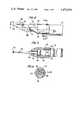
- FIG. 2is a view in section taken along lines 2--2 of FIG. 1;
- FIG. 3is a view in section similar to FIG. 2 but showing the ski member of the knife fully retracted;
- FIG. 4is an enlarged side view in plan of the forward end of the knife of FIG. 1;
- FIG. 5is a view in section taken along lines 5--5 of FIG. 4;
- FIG. 6is a view in section taken along lines 6--6 of FIG. 4;
- FIG. 7is an exploded view in perspective of the forward end of the knife of FIG. 1;
- FIG. 8is a side view in plan of a knife in accordance with a second embodiment of the present invention wherein the blade is a ventral-type blade;
- FIG. 9is a side view in plan of the knife of FIG. 8 wherein the blade is a dorsal-type blade;
- FIG. 10is an exploded view in perspective of a blade cartridge employed in the embodiment of FIGS. 8 and 9;
- FIG. 11is an exploded side view in plan of the cartridge and nose portion of the knife embodiment of FIGS. 8 and 9;
- FIG. 12is a view in section taken along lines 12--12 of FIG. 11;
- FIG. 13is a plan view of a ventral-type blade which can be substituted for the dorsal-type blade employed in FIG. 10.
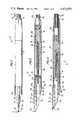
- a surgical knifeincludes seven (7) basic parts, namely: an elongated body member 12; a spindle 14; a ski shaft 16; a nose member 18; a saddle member 20; a blade 22; and a blade clamp member 24.
- Body member 12has a generally cylindrical profile and has a bore 26 defined therethrough along its entire length. Bore 26 has a cylindrical threaded portion 28 near its proximal end 30. A second threaded portion 32 of bore 26 is located near the distal end 34 of body member 12.
- Spindle 14is an elongated member having an externally threaded sector 36 which cooperatively engages with the bore 26.
- the proximal end of spindle 14is provided with a series of angularly spaced longitudinally-extending grooves defining a handle which projects rearwardly from the proximal end 30 of body member 12.
- the distal end of spindle 14has a threaded bore 40 defined therein and extending longitudinally rearward to the spindle. Threaded bore 40 constitutes a second threaded sector of the spindle 14.
- the overall length of spindle 14is somewhat shorter than the length of body member 12 and the mutually engaged threaded bore portion 28 and threaded sector 36 are arranged so that at least a portion of the grooves 38 in the spindle handle are exposed at the proximal end 30 of body member 12.
- annular ledge 42is defined in bore 26 at the end of threaded portion 28 remote from proximal end 30 of the body member 12.
- An enlarged radial portion 44 of spindle 14cooperates with annular ledge 42 to limit axial displacement of spindle 14 in the direction of proximal end 30 of body member 12.
- the ski shaft 16has an externally threaded segment 46 extending from near its proximal end for a substantial distance along the ski shaft length. Proceeding in the direction of the distal end of ski shaft 14, a short cylindrical section of the ski shaft separates the threaded segment 46 from a coaxially disposed segment 48 of rectangular transverse cross-section. In the particular embodiment illustrated, segment 48 has a square cross-section. Segment 48 projects from the distal end 34 of body member 12 whereupon it tapers with a decreasing rectangular cross-section. The distal end of shaft 16 bends at an acute angle relative to the common longitudinal axis of shaft 16 until reaching its terminus which takes the form of a flat ski member 50 bent perpendicular to the longitudinal axis of the shaft and extending beyond the profile of body member 12.
- ski member 50The radial or transverse extremity of ski member 50 is provided with a transversely or radially extending slot 52 which serves to bifurcate the ski member.
- the threaded segment 46 of the ski shaftcooperatively engages the threaded bore 40 of spindle 14.
- the threads of threaded bore section 28 of body member 12 and externally threaded sector 36 of the spindleare in the same direction as the threads in threaded bore section 40 of the spindle and externally threaded segment 46 of the ski shaft.
- Nose member 18has a cylindrical threaded portion 54 disposed at one end and arranged to cooperatively engage the second threaded portion 32 of body member 12. This threaded portion 54 of nose member 18 is received in bore 26 at the distal end 34 of body member 12.
- the rectangular cross-section of the nose membertapers in the distal direction.
- a bore 58is defined longitudinally through nose member 18 and, throughout portion 56 has a cross-section which matches the cross-section of segment 48 of the ski shaft 16.
- Bore 58thus serves as a guide member to permit longitudinal translation of shaft 16 therethrough but limiting rotation of shaft 16 relative to the nose member 18. Since the nose member 18 is secured to body member 12 by means of threaded portions 32 and 54, bore 58 also precludes rotation of shaft 16 relative to body member 12.
- Two (2) opposite sides of section 56 of the nose memberare provided with opposed recesses 60 which define an imaginary plane that is perpendicular to the longitudinal axis of ski shaft 16. These recesses 60, which are best illustrated in FIGS. 5 and 7, cooperate with radially-inward extending lips 62 of saddle member 20 to maintain the saddle member fixed in position relative to nose member 18.
- Saddle member 20is provided with a longitudinally-extending channel having two (2) sections 64 and 66 of different configuration.
- channel section 64fits over the top of the radially enlarged section 56 of nose member 18. Suitable cut-away portions of channel 64 are provided so as to engage the corners of the rectangular portion 56 and thereby preclude relative rotation between nose member 18 and the saddle member 20.
- One longitudinal end of channel section 64is demarked by ribs 62 which, as noted above, engage the recesses 60 in nose member section 56 to prevent longitudinal displacement between the nose member 18 and saddle member 20.
- the other end of channel section 64terminates in a generally U-shaped shoulder 68 which defines one end of channel section 66. This channel section is disposed about a portion of segment 48 of the ski shaft 16 which is slidable through channel section 66 as it moves longitudinally through bore 58 in nose member 18.
- the forward end of saddle member 20has a forwardly projecting finger 70 with a substantially planar surface extending parallel to the longitudinal axis of saddle member 20 and body member 12.
- Two (2) longitudinally spaced transversely projecting cylindrical stubsextend from surface 74 and project through two (2) similarly spaced holes 76 defined transversely through blade 22.
- Blade clamp 24has a flat surface which abuts the side of blade 22 opposite surface 72 of finger 70 and includes two (2) spaced bores 78 which receive stubs 74.
- the clamp 24 and saddle 20are made of a plastic material which is heat-treatable such that stubs 74, when subjected to heat, form a bond with the blade clamp 24 in bores 78.
- the blade 22is thus firmly held in place by the joined blade clamp 24 and projecting finger 70.
- the bladewhen thusly held, is longitudinally aligned with slot 52 in ski member 50.
- the cutting edge of the bladeprojects transversely slightly beyond the profile of body member 12 so that the cutting edge can be readily viewed by the user of the device making an incision without undue manipulation of body member 12.
- ski shaft 16which is prevented from rotating by nose member 18, is retracted into the spindle. If, as assumed in the present case, the pitch between threades of threaded bore 40 and externally threaded segment 46 is greater than the pitch between threads between threaded bore portion 28 and externally threaded segment 36, the net axial displacement of ski 50 is toward housing member 12. In other words, if spindle 14 is rotated one full turn relative to housing 12, the net axial displacement of the spindle with respect to the housing equals the pitch of the threads in sector 36 and bore portion 28. This, of itself, would tend to displace ski 50 to the left as viewed in FIG. 2.
- ski shaft 16is prevented from rotating, a one turn advancement of spindle 14 produces a one turn retraction of ski shaft 16 into the spindle. This superimposes a movement to the right, as viewed in FIG. 2, of the ski shaft 16 and ski 50.
- the net displacement of the ski member 50is the thread pitch of sector 40 minus the thread pitch of sector 36.
- This differential thread relationshippermits very fine and precise control of the axial displacement of ski shaft 50.
- Axial insertion of the spindle 14 into body member 12is limited by the end of nose member 18 which abuts the end of spindle 14 when the spindle is fully inserted.
- the range of permissible axial displacement of spindle 14 within body member 12is selected to permit ski member 50 to move between one extreme position, illustrated in FIG.
- FIG. 3the position of the ski member 50 in FIG. 2 is such that the ski member projects beyond the distal extremity of blade 22 so that no portion of the blade extends beyond the ski member.
- the bladeis illustrated as projecting through the slot in ski member 50 to expose some predetermined maximum length of the blade beyond the ski member.
- the amount of blade projection beyond the ski membercan be adjusted by appropriately positioning spindle 14 in body member 12.
- the blade memberdoes not move; rather, it is the ski member 50 that is translated longitudinally to expose more or less of the blade through slot 52.
- the blade clamp assembly 24 and blade 22, along with saddle member 20may be readily removed from the assembly by forcing ribs 62 out of engagement with recesses 60 and sliding the the saddle member 20 over the ski shaft and ski member 50.
- the saddle, blade clamp and bladeare disposable, and can be replaced after use.
- the degree of control of translation of ski member 50is, of course, dependent upon the difference between the pitches in threaded sectors 36 and 40 of the spindle.
- the pitch of the threads in sector 40 and segment 46is 1/28 inch or 0.0357 inch.
- the corresponding pitch in externally threaded sector 36 and threaded bore portion 28is 1/36 inch or 0.0278 inch.
- the full range of axial displacement of ski member 50is 0.125 inches.
- the blade member 22 for such an embodimentis typically 5/8 inch with a length of cutting edge 80 equal to approximately 0.233 inch.
- FIGS. 8-13A second embodiment 90 of the knife of the present invention is illustrated in FIGS. 8-13 wherein identical parts for those illustrated in FIGS. 1-7 bear the same reference numerals.
- knife 90includes an elongated body member 12, a spindle 14, a ski shaft 16, a nose member 92, a ventral-type blade 94, and a blade cartridge assembly 96.
- Knife 90differs from knife 10 primarily by the elimination of saddle member 20 and the corresponding change in the structure of nose member 92 and the replacement of the blade clamp member 24 by the cartridge assembly 96.
- the interengagement of body member 12, spindle 14, and ski shaft 16is identical to that described hereinabove in relation to knife 10 of FIGS. 1-7; therefore, this engagement will not be described in relation to knife 90.
- the blade cartridge assembly 96includes a pair of elongated members 101 and 103 which are generally semicylindrical with rounded front ends and which are adapted to fit together with a knife blade 105 therebetween.
- Member 101has a surface 107 which, when the cartridge is assembled, mates with a similar surface of member 103.
- Surface 107has a generally elongated recess 109 extending from its forward end in a rearward direction longitudinally of member 101.
- a similar recess(not visible in FIG. 10) is defined in the mating surface of member 103 so as to be aligned with recess 109.
- a plurality of stubs 111extend perpendicularly from surface 107 and are longitudinally spaced along that surface.
- Member 103on its mating surface, is provided with a plurality of bore (not illustrated), each of which is adapted to receive a respective stub 111 when members 101 and 103 are placed together.
- Two (2) of the stubs 111extend from member 101 in the region of recess 109. Suitable holes 113 are provided in the knife blade 105 so that these stubs may project through holes 113 into the appropriate bores in member 103.
- Each of members 101 and 103include an intermediate longitudinal portion 115 of reduced thickness. Rearwardly of these portions 115 there is provided a radially extending wing-like member 117 which has a flat bottom surface and an arcuate top surface which converges toward the bottom surface to meet that surface in a straight edge.
- the nose member 92includes a generally cylindrical rearward section 119 which is hollow to permit the threaded shaft of ski member 16 to pass therethrough.
- a forward portion 121 of the nose memberis also hollow for this purpose and is provided with a longitudinally extending slot along its top side for receiving the recessed portion 115 of the assembled blade cartridge 96.
- Slot 123is configured such that when the cartridge 96 is placed therein, blade member 105 projects forwardly and in alignment with the slot 52 in ski member 50 of the ski shaft 16.
- the longitudinally-extending upper edges 125 of slot 123are bent inwardly so that the cartridge 96 can be snapped into slot 123 and engaged therein by the converging lips 125.
- the snap-fit of the cartridge in channel 123thus holds the two (2) members 101 and 103 together with the knife blade 105 therebetween. This eliminates the need for a special step to assemble cartridge members 101 and 103 during the assembly of the overall knife unit.
- ventral-type blade 106is illustrated with suitable through holes 113 defined therein for mating with stubs 111.
- the ventral-type knife blade 106can readily be substituted for the dorsal-type knife blade 105 illustrated in FIG. 1 so that the overall knife assembly can be fabricated irrespective of the blade type.
- the rearward portion 119 of the nose memberis inserted in the forward end of body member 12 when the unit is finally assembled so that the ski shaft 16 projects forwardly from the body member 12, through the nose member 92 and forwardly of cartridge 96.
- the threaded engagement between the ski shaft and spindle 14, and the threaded engagement between the spindle 14 and body member 12remain the same as described above in relation to FIGS. 1-7.
- All of the parts of the embodiments of FIGS. 8-13, except for the knife blades 94, 98, 105, and 106may be made of injection molded plastic. These parts, as described above, are easily and quickly assembled so that a minimum of manufacturing time and expense is involved. Therefore, the entire keratotomy knife assembly 90 is disposable after a single use.
- the bore 122 which extends longitudinally through the forward section 121 of nose member 92has a cross-section which matches the periphery 48 of the ski shaft 16 passing through this part of the nose member.
- bore 122has a square cross-section so as to serve as a guide to permit longitudinal translation of the ski shaft 16 therethrough; however, ski shaft 16 is prevented from rotating relative to the nose member by virtue of this bore configuration.
- the rearward section 119 of nose member 92is force-fitted into the forward end of body member 12, both the nose member and the ski shaft are prevented from rotating relative to the body member.
- the ski shaft 16in the manner described above in relation to FIGS. 1-3, is caused to slide longitudinally relative to the knife blade to thereby selectively expose more or less of the blade as desired.
- the position of the knife blade relative to the profile of the body memberis substantially the same as described above in relation to the embodiments of FIGS. 1-7.
- the surgical knife described hereinis an improvement over the prior art by virtue of the fact that the ski member is translatable longitudinally rather than the blade member and that the bifurcated ski member 50 and cutting edge 80 extend transversely beyond the profile of body member 12.
- the unitis inexpensive and entirely disposable, thereby rendering the relatively more expensive extension and retraction mechanism reusable.
Landscapes
- Health & Medical Sciences (AREA)
- Surgery (AREA)
- Life Sciences & Earth Sciences (AREA)
- Engineering & Computer Science (AREA)
- Veterinary Medicine (AREA)
- Biomedical Technology (AREA)
- Heart & Thoracic Surgery (AREA)
- Ophthalmology & Optometry (AREA)
- Nuclear Medicine, Radiotherapy & Molecular Imaging (AREA)
- Animal Behavior & Ethology (AREA)
- General Health & Medical Sciences (AREA)
- Public Health (AREA)
- Vascular Medicine (AREA)
- Dermatology (AREA)
- Medical Informatics (AREA)
- Molecular Biology (AREA)
- Surgical Instruments (AREA)
Abstract
Description
Claims (20)
Priority Applications (1)
| Application Number | Priority Date | Filing Date | Title |
|---|---|---|---|
| US06/366,154US4473076A (en) | 1982-04-07 | 1982-04-07 | Surgical knife |
Applications Claiming Priority (1)
| Application Number | Priority Date | Filing Date | Title |
|---|---|---|---|
| US06/366,154US4473076A (en) | 1982-04-07 | 1982-04-07 | Surgical knife |
Publications (1)
| Publication Number | Publication Date |
|---|---|
| US4473076Atrue US4473076A (en) | 1984-09-25 |
Family
ID=23441871
Family Applications (1)
| Application Number | Title | Priority Date | Filing Date |
|---|---|---|---|
| US06/366,154Expired - LifetimeUS4473076A (en) | 1982-04-07 | 1982-04-07 | Surgical knife |
Country Status (1)
| Country | Link |
|---|---|
| US (1) | US4473076A (en) |
Cited By (50)
| Publication number | Priority date | Publication date | Assignee | Title |
|---|---|---|---|---|
| US4499898A (en)* | 1982-08-23 | 1985-02-19 | Koi Associates | Surgical knife with controllably extendable blade and gauge therefor |
| US4569133A (en)* | 1983-01-06 | 1986-02-11 | Sharpoint, Inc. | Depth limited cutter |
| WO1986003397A1 (en)* | 1984-12-08 | 1986-06-19 | Rolf Sohni | Surgical lancet having a blade preferably shaped as a diamond blade |
| US4601710A (en)* | 1983-08-24 | 1986-07-22 | Endotherapeutics Corporation | Trocar assembly |
| US4630378A (en)* | 1985-06-13 | 1986-12-23 | Pilling Co. | Gauge for extensible-blade surgical knife |
| WO1987001272A1 (en)* | 1985-08-29 | 1987-03-12 | Coopervision, Inc. | Radial keratotomy knife and system using same |
| WO1987001576A1 (en)* | 1985-09-17 | 1987-03-26 | Jensen Ronald P | Scalpel with removable depth guard |
| WO1987005799A1 (en)* | 1983-07-05 | 1987-10-08 | Moskovsky Nauchno-Issledovatelsky Institut Mikrokh | Device for carrying out ophtalmological operations |
| EP0251485A1 (en)* | 1986-06-13 | 1988-01-07 | Cilco, Inc. | Surgical scalpel |
| US4768509A (en)* | 1985-12-07 | 1988-09-06 | Duckworth & Kent Surgical Instruments Limited | Surgical knife |
| US4790312A (en)* | 1987-01-20 | 1988-12-13 | Becton Dickinson Acutecare, Inc. | Surgical knife |
| US4823457A (en)* | 1988-04-20 | 1989-04-25 | American Safety Razor Company | Disposable surgical scalpel |
| US4884569A (en)* | 1983-07-05 | 1989-12-05 | Mezhotraslevoi Nauchno-Tekhnichesky Komplex "Mikrokhirurgia Glaza" | Device for ophthalmologic operations |
| US4898170A (en)* | 1985-08-01 | 1990-02-06 | Duckworth & Kent Surgical Instruments Limited | Surgical knife |
| US5071427A (en)* | 1990-02-05 | 1991-12-10 | Stahl Norman O | Surgical knife assembly including depth guard |
| US5085663A (en)* | 1989-12-27 | 1992-02-04 | Bernard Tarr | Surgical knife with angular cut control and method of using the same |
| US5122152A (en)* | 1989-02-24 | 1992-06-16 | Mull John D | Suture removing device |
| US5246425A (en)* | 1992-09-21 | 1993-09-21 | Daniel Hunsberger | Trocar and cannula assembly |
| US5254128A (en)* | 1990-10-11 | 1993-10-19 | Micro Engineering, Inc. | Surgical knife with attached, movable blade protector |
| US5256147A (en)* | 1992-06-17 | 1993-10-26 | Minnesota Mining And Manufacturing Company | Reusable trocar with easily replaceable obturator |
| US5323543A (en)* | 1992-09-29 | 1994-06-28 | Keratron Group | Apparatus and method for calibrating a surgical knife |
| USD354565S (en) | 1993-02-22 | 1995-01-17 | Richard-Allan Medical Industries, Inc. | Trocar converter |
| US5443474A (en)* | 1994-03-07 | 1995-08-22 | Implemed, Inc. | Meniscectomy knife |
| USD364683S (en) | 1993-03-05 | 1995-11-28 | Feather Safety Razor Co., Ltd. | Surgical knife depth gauge |
| US5538509A (en)* | 1994-01-31 | 1996-07-23 | Richard-Allan Medical Industries, Inc. | Trocar assembly |
| US5545172A (en)* | 1994-06-07 | 1996-08-13 | Malvern Technologies, Inc. | Rocking foot plate for surgical knife |
| US5569283A (en)* | 1993-09-03 | 1996-10-29 | United States Surgical Corporation | Surgical cutting instrument with guarded blade |
| US5681262A (en)* | 1994-10-05 | 1997-10-28 | Very Inventive Physicians Inc. | Endoscope and tool therefore |
| US5843091A (en)* | 1995-05-12 | 1998-12-01 | Ballard Medical Products | Extension regulator for catheter carried medical instruments |
| US5876416A (en)* | 1997-09-05 | 1999-03-02 | Hill; Frank C. | Surgical knife |
| US6453559B1 (en)* | 1999-03-06 | 2002-09-24 | Peter Jonathan Marshall | Safety knife |
| WO2002071990A3 (en)* | 2001-03-09 | 2003-03-20 | View Point Technology Ag | Blade fixture for a surgical instrument and method for fastening a blade |
| US6615495B1 (en)* | 1999-04-27 | 2003-09-09 | Worldcom, Inc. | Apparatus and method for perforating package coverings |
| US6726690B2 (en)* | 2002-01-17 | 2004-04-27 | Concept Matrix, Llc | Diskectomy instrument and method |
| US6770066B1 (en) | 1992-05-11 | 2004-08-03 | Ballard Medical Products | Multi-lumen endoscopic catheter |
| US20040230155A1 (en)* | 1999-06-22 | 2004-11-18 | Erblan Surgical Inc. | Insufflator and method of use |
| US20040230160A1 (en)* | 2000-06-22 | 2004-11-18 | Erblan Surgical Inc. | Safety trocar including sealing member |
| US20050055041A1 (en)* | 2003-09-05 | 2005-03-10 | Sightrate B.V. | Device for separation of corneal epithelium |
| US20050216019A1 (en)* | 2002-01-17 | 2005-09-29 | Eckman Walter W | Diskectomy instrument with disposable blade head |
| US20060015075A1 (en)* | 1999-06-22 | 2006-01-19 | Erblan Surgical Inc. | Guarded infusor needle and infusor locking system |
| US20060167467A1 (en)* | 2000-07-10 | 2006-07-27 | Endotex Interventional Systems, Inc. | Stent delivery device |
| US20060195127A1 (en)* | 2002-01-25 | 2006-08-31 | Terumo Kabushiki Kaisha | Vascular incision method |
| USD549344S1 (en) | 2003-01-16 | 2007-08-21 | Concept Matrix, Llc | Diskectomy tool with convex head |
| US20080009896A1 (en)* | 2006-07-06 | 2008-01-10 | I-Sen Shiao | Micro-implanter for hair follicle |
| US20080243158A1 (en)* | 2007-03-30 | 2008-10-02 | Lee Morgan | Scalpel Blade Holder |
| US20090024121A1 (en)* | 2001-12-28 | 2009-01-22 | Olympus Corporation | Treatment device for cutting living tissue |
| US20100024219A1 (en)* | 2008-07-30 | 2010-02-04 | Alltrade Tools Llc | Hobby knife |
| US7708750B2 (en) | 2001-07-23 | 2010-05-04 | Fos Holdings S.A. | Device for separating the epithelium layer from the surface of the cornea of an eye |
| US20150045797A1 (en)* | 2013-08-07 | 2015-02-12 | Arthrex, Inc. | Meniscal probe cutter |
| US12433788B2 (en) | 2021-05-17 | 2025-10-07 | Alcon Inc. | Ophthalmic surgical tool |
Citations (6)
| Publication number | Priority date | Publication date | Assignee | Title |
|---|---|---|---|---|
| US1195169A (en)* | 1916-08-22 | Masvin e | ||
| US2473968A (en)* | 1946-11-15 | 1949-06-21 | Paton Richard Townley | Corneal trephine |
| US2941511A (en)* | 1955-12-27 | 1960-06-21 | Reynolds Pen Company Of New Yo | Writing implement with retractable guard sleeve |
| US3945117A (en)* | 1973-02-15 | 1976-03-23 | Rudolph Beaver, Inc. | Surgical blade with adjustable blade guard |
| US3967377A (en)* | 1975-03-17 | 1976-07-06 | Wells Royzell F | Precision positioning device for tool blades and the like |
| US4027295A (en)* | 1973-12-01 | 1977-05-31 | Fujitsu Ltd. | Magnetic bubble device |
- 1982
- 1982-04-07USUS06/366,154patent/US4473076A/ennot_activeExpired - Lifetime
Patent Citations (6)
| Publication number | Priority date | Publication date | Assignee | Title |
|---|---|---|---|---|
| US1195169A (en)* | 1916-08-22 | Masvin e | ||
| US2473968A (en)* | 1946-11-15 | 1949-06-21 | Paton Richard Townley | Corneal trephine |
| US2941511A (en)* | 1955-12-27 | 1960-06-21 | Reynolds Pen Company Of New Yo | Writing implement with retractable guard sleeve |
| US3945117A (en)* | 1973-02-15 | 1976-03-23 | Rudolph Beaver, Inc. | Surgical blade with adjustable blade guard |
| US4027295A (en)* | 1973-12-01 | 1977-05-31 | Fujitsu Ltd. | Magnetic bubble device |
| US3967377A (en)* | 1975-03-17 | 1976-07-06 | Wells Royzell F | Precision positioning device for tool blades and the like |
Non-Patent Citations (2)
| Title |
|---|
| "A Micrometer Knife", Albrecht, Transactions AAOO, Mar., Apr., 1972. |
| A Micrometer Knife , Albrecht, Transactions AAOO, Mar., Apr., 1972.* |
Cited By (63)
| Publication number | Priority date | Publication date | Assignee | Title |
|---|---|---|---|---|
| US4499898A (en)* | 1982-08-23 | 1985-02-19 | Koi Associates | Surgical knife with controllably extendable blade and gauge therefor |
| US4569133A (en)* | 1983-01-06 | 1986-02-11 | Sharpoint, Inc. | Depth limited cutter |
| US4884569A (en)* | 1983-07-05 | 1989-12-05 | Mezhotraslevoi Nauchno-Tekhnichesky Komplex "Mikrokhirurgia Glaza" | Device for ophthalmologic operations |
| WO1987005799A1 (en)* | 1983-07-05 | 1987-10-08 | Moskovsky Nauchno-Issledovatelsky Institut Mikrokh | Device for carrying out ophtalmological operations |
| US4601710A (en)* | 1983-08-24 | 1986-07-22 | Endotherapeutics Corporation | Trocar assembly |
| WO1986003397A1 (en)* | 1984-12-08 | 1986-06-19 | Rolf Sohni | Surgical lancet having a blade preferably shaped as a diamond blade |
| US4630378A (en)* | 1985-06-13 | 1986-12-23 | Pilling Co. | Gauge for extensible-blade surgical knife |
| US4898170A (en)* | 1985-08-01 | 1990-02-06 | Duckworth & Kent Surgical Instruments Limited | Surgical knife |
| US4750489A (en)* | 1985-08-29 | 1988-06-14 | Coopervision, Inc. | Radial keratotomy knife and system using same |
| AU603065B2 (en)* | 1985-08-29 | 1990-11-08 | Nestle S.A. | Radial keratotomy knife and system using same |
| WO1987001272A1 (en)* | 1985-08-29 | 1987-03-12 | Coopervision, Inc. | Radial keratotomy knife and system using same |
| WO1987001576A1 (en)* | 1985-09-17 | 1987-03-26 | Jensen Ronald P | Scalpel with removable depth guard |
| US4759363A (en)* | 1985-09-17 | 1988-07-26 | Jensen Ronald P | Scalpel with removable depth guard |
| US4768509A (en)* | 1985-12-07 | 1988-09-06 | Duckworth & Kent Surgical Instruments Limited | Surgical knife |
| EP0251485A1 (en)* | 1986-06-13 | 1988-01-07 | Cilco, Inc. | Surgical scalpel |
| US4790312A (en)* | 1987-01-20 | 1988-12-13 | Becton Dickinson Acutecare, Inc. | Surgical knife |
| US4823457A (en)* | 1988-04-20 | 1989-04-25 | American Safety Razor Company | Disposable surgical scalpel |
| US5122152A (en)* | 1989-02-24 | 1992-06-16 | Mull John D | Suture removing device |
| US5085663A (en)* | 1989-12-27 | 1992-02-04 | Bernard Tarr | Surgical knife with angular cut control and method of using the same |
| US5071427A (en)* | 1990-02-05 | 1991-12-10 | Stahl Norman O | Surgical knife assembly including depth guard |
| US5254128A (en)* | 1990-10-11 | 1993-10-19 | Micro Engineering, Inc. | Surgical knife with attached, movable blade protector |
| US6770066B1 (en) | 1992-05-11 | 2004-08-03 | Ballard Medical Products | Multi-lumen endoscopic catheter |
| US5256147A (en)* | 1992-06-17 | 1993-10-26 | Minnesota Mining And Manufacturing Company | Reusable trocar with easily replaceable obturator |
| US5246425A (en)* | 1992-09-21 | 1993-09-21 | Daniel Hunsberger | Trocar and cannula assembly |
| US5323543A (en)* | 1992-09-29 | 1994-06-28 | Keratron Group | Apparatus and method for calibrating a surgical knife |
| USD354565S (en) | 1993-02-22 | 1995-01-17 | Richard-Allan Medical Industries, Inc. | Trocar converter |
| USD364683S (en) | 1993-03-05 | 1995-11-28 | Feather Safety Razor Co., Ltd. | Surgical knife depth gauge |
| US5569283A (en)* | 1993-09-03 | 1996-10-29 | United States Surgical Corporation | Surgical cutting instrument with guarded blade |
| US5538509A (en)* | 1994-01-31 | 1996-07-23 | Richard-Allan Medical Industries, Inc. | Trocar assembly |
| US5941852A (en)* | 1994-01-31 | 1999-08-24 | Imagyn Medical Technologies California, Inc. | Trocar assembly |
| US5443474A (en)* | 1994-03-07 | 1995-08-22 | Implemed, Inc. | Meniscectomy knife |
| US5545172A (en)* | 1994-06-07 | 1996-08-13 | Malvern Technologies, Inc. | Rocking foot plate for surgical knife |
| US5681262A (en)* | 1994-10-05 | 1997-10-28 | Very Inventive Physicians Inc. | Endoscope and tool therefore |
| US5843091A (en)* | 1995-05-12 | 1998-12-01 | Ballard Medical Products | Extension regulator for catheter carried medical instruments |
| US5876416A (en)* | 1997-09-05 | 1999-03-02 | Hill; Frank C. | Surgical knife |
| US6453559B1 (en)* | 1999-03-06 | 2002-09-24 | Peter Jonathan Marshall | Safety knife |
| US6615495B1 (en)* | 1999-04-27 | 2003-09-09 | Worldcom, Inc. | Apparatus and method for perforating package coverings |
| US20060015075A1 (en)* | 1999-06-22 | 2006-01-19 | Erblan Surgical Inc. | Guarded infusor needle and infusor locking system |
| US20040230155A1 (en)* | 1999-06-22 | 2004-11-18 | Erblan Surgical Inc. | Insufflator and method of use |
| US20040230160A1 (en)* | 2000-06-22 | 2004-11-18 | Erblan Surgical Inc. | Safety trocar including sealing member |
| US7819882B2 (en)* | 2000-07-10 | 2010-10-26 | Boston Scientific Cupertino Corporation | Stent delivery device |
| US20060167467A1 (en)* | 2000-07-10 | 2006-07-27 | Endotex Interventional Systems, Inc. | Stent delivery device |
| WO2002071990A3 (en)* | 2001-03-09 | 2003-03-20 | View Point Technology Ag | Blade fixture for a surgical instrument and method for fastening a blade |
| US7708750B2 (en) | 2001-07-23 | 2010-05-04 | Fos Holdings S.A. | Device for separating the epithelium layer from the surface of the cornea of an eye |
| US8425508B2 (en)* | 2001-12-28 | 2013-04-23 | Olympus Corporation | Treatment device for cutting living tissue |
| US20090024121A1 (en)* | 2001-12-28 | 2009-01-22 | Olympus Corporation | Treatment device for cutting living tissue |
| US7699849B2 (en) | 2002-01-17 | 2010-04-20 | Concept Matrix, Llc | Diskectomy instrument with disposable blade head |
| US6939351B2 (en) | 2002-01-17 | 2005-09-06 | Concept Matrix, Llc | Diskectomy instrument and method |
| US20050216019A1 (en)* | 2002-01-17 | 2005-09-29 | Eckman Walter W | Diskectomy instrument with disposable blade head |
| US6726690B2 (en)* | 2002-01-17 | 2004-04-27 | Concept Matrix, Llc | Diskectomy instrument and method |
| US20050038439A1 (en)* | 2002-01-17 | 2005-02-17 | Concept Matrix, Llc | Diskectomy instrument and method |
| US20060195127A1 (en)* | 2002-01-25 | 2006-08-31 | Terumo Kabushiki Kaisha | Vascular incision method |
| US7727250B2 (en)* | 2002-01-25 | 2010-06-01 | Terumo Kabushiki Kaisha | Vascular incision method |
| USD549344S1 (en) | 2003-01-16 | 2007-08-21 | Concept Matrix, Llc | Diskectomy tool with convex head |
| US20050055041A1 (en)* | 2003-09-05 | 2005-03-10 | Sightrate B.V. | Device for separation of corneal epithelium |
| US20080009896A1 (en)* | 2006-07-06 | 2008-01-10 | I-Sen Shiao | Micro-implanter for hair follicle |
| US10517640B2 (en)* | 2006-07-06 | 2019-12-31 | Follicular Technologies, Llc | Micro-implanter for hair follicle |
| US20080243158A1 (en)* | 2007-03-30 | 2008-10-02 | Lee Morgan | Scalpel Blade Holder |
| US9421031B2 (en)* | 2007-03-30 | 2016-08-23 | Lee Morgan | Scalpel blade holder |
| US20100024219A1 (en)* | 2008-07-30 | 2010-02-04 | Alltrade Tools Llc | Hobby knife |
| US20150045797A1 (en)* | 2013-08-07 | 2015-02-12 | Arthrex, Inc. | Meniscal probe cutter |
| US10646234B2 (en)* | 2013-08-07 | 2020-05-12 | Arthrex, Inc. | Meniscal probe cutter |
| US12433788B2 (en) | 2021-05-17 | 2025-10-07 | Alcon Inc. | Ophthalmic surgical tool |
Similar Documents
| Publication | Publication Date | Title |
|---|---|---|
| US4473076A (en) | Surgical knife | |
| US4499898A (en) | Surgical knife with controllably extendable blade and gauge therefor | |
| US4569133A (en) | Depth limited cutter | |
| US4576164A (en) | Knife with locking shroud | |
| US5254128A (en) | Surgical knife with attached, movable blade protector | |
| US5620453A (en) | Surgical knife with retractable blade and depth of cut control | |
| US4660287A (en) | Knife with replaceable blade | |
| US4111207A (en) | Notched tubular cutting instrument | |
| US4538356A (en) | Surgical knife with controllably extendable blade and gauge therefor | |
| CA1252363A (en) | Sheathed knife instrument | |
| US5484447A (en) | Calipers for use in ophthalmic surgery | |
| US5292330A (en) | Retractable surgical instrument with curved operative element | |
| JP2005246077A (en) | Obturator | |
| DE69527019T2 (en) | Hair clipper with disposable blade unit | |
| US5662646A (en) | Method and apparatus for laser surgery | |
| US3657812A (en) | Retractible tool holder | |
| US5431671A (en) | Surgical knife with retractable and angularly adjustable blade | |
| US4534348A (en) | Instrument for making corneal incisions | |
| GB2113550A (en) | Surgical knife | |
| US5571128A (en) | Safety surgical instrument | |
| GB2140735A (en) | Forceps having a handle and an exchangeable forceps insert | |
| EP0389007A1 (en) | Wet shaver | |
| WO1987001928A1 (en) | Intraocular surgical instrument | |
| PT92380A (en) | CUTTING STRIPPING TOOL | |
| US12137921B2 (en) | Surgical bone preparation instrument and assembly comprising such an instrument |
Legal Events
| Date | Code | Title | Description |
|---|---|---|---|
| AS | Assignment | Owner name:VXTRA DEVELOPMENT LIMITED, 700 DIVISION, NASHVILLE Free format text:ASSIGNMENT OF ASSIGNORS INTEREST.;ASSIGNORS:WILLIAMS, RODGER W.;RAYMOND, DALE W.;ATWOOD, CHARLES W.;REEL/FRAME:004005/0488 Effective date:19820423 | |
| STCF | Information on status: patent grant | Free format text:PATENTED CASE | |
| FEPP | Fee payment procedure | Free format text:PAYOR NUMBER ASSIGNED (ORIGINAL EVENT CODE: ASPN); ENTITY STATUS OF PATENT OWNER: LARGE ENTITY | |
| FPAY | Fee payment | Year of fee payment:4 | |
| FEPP | Fee payment procedure | Free format text:PAYER NUMBER DE-ASSIGNED (ORIGINAL EVENT CODE: RMPN); ENTITY STATUS OF PATENT OWNER: LARGE ENTITY Free format text:PAYOR NUMBER ASSIGNED (ORIGINAL EVENT CODE: ASPN); ENTITY STATUS OF PATENT OWNER: LARGE ENTITY Free format text:PAT HLDR NO LONGER CLAIMS SMALL ENT STAT AS INDIV INVENTOR (ORIGINAL EVENT CODE: LSM1); ENTITY STATUS OF PATENT OWNER: LARGE ENTITY | |
| FPAY | Fee payment | Year of fee payment:8 | |
| FPAY | Fee payment | Year of fee payment:12 | |
| AS | Assignment | Owner name:ALCON MANUFACTURING, LTD., TEXAS Free format text:ASSIGNMENT OF ASSIGNORS INTEREST;ASSIGNOR:ALCON LABORATORIES, INC.;REEL/FRAME:011667/0559 Effective date:20010322 |