US4472877A - Tool for removing insulation from cables - Google Patents
Tool for removing insulation from cablesDownload PDFInfo
- Publication number
- US4472877A US4472877AUS06/330,661US33066181AUS4472877AUS 4472877 AUS4472877 AUS 4472877AUS 33066181 AUS33066181 AUS 33066181AUS 4472877 AUS4472877 AUS 4472877A
- Authority
- US
- United States
- Prior art keywords
- handle
- housing
- cutting blade
- holder
- pin
- Prior art date
- Legal status (The legal status is an assumption and is not a legal conclusion. Google has not performed a legal analysis and makes no representation as to the accuracy of the status listed.)
- Expired - Fee Related
Links
Images
Classifications
- H—ELECTRICITY
- H02—GENERATION; CONVERSION OR DISTRIBUTION OF ELECTRIC POWER
- H02G—INSTALLATION OF ELECTRIC CABLES OR LINES, OR OF COMBINED OPTICAL AND ELECTRIC CABLES OR LINES
- H02G1/00—Methods or apparatus specially adapted for installing, maintaining, repairing or dismantling electric cables or lines
- H02G1/12—Methods or apparatus specially adapted for installing, maintaining, repairing or dismantling electric cables or lines for removing insulation or armouring from cables, e.g. from the end thereof
- H02G1/1202—Methods or apparatus specially adapted for installing, maintaining, repairing or dismantling electric cables or lines for removing insulation or armouring from cables, e.g. from the end thereof by cutting and withdrawing insulation
- H02G1/1204—Hand-held tools
- H02G1/1229—Hand-held tools the cutting element making a longitudinal, and a transverse or a helical cut
- H02G1/1231—Hand-held tools the cutting element making a longitudinal, and a transverse or a helical cut using a swivelling cutting element
Definitions
- the present inventionis directed to a tool for removing the insulation from cables.
- the cable end to be strippedis held in place by a holder stirrup and a stripping blade pierces the insulation at a single location.
- the toolis turned by moving a rod-shaped handle around the cable so that the original hole formed by the cutting or stripping blade is extended circumferentially around the cable.
- the bladeis rotated about its own axis through 90° and the tool is moved in the axial direction of the cable slitting the insulation so that it can be easily removed.
- Tools of this typeare known, for instance note British Patent Specification No. 1 458 366.
- the primary object of the present inventionis to improve the tool mentioned above, particularly to afford convenient handling and reliable functioning when stripping insulation from large diameter cables.
- a tool for removing insulation from cablesparticularly large diameter cables, includes a cutting blade positioned in a housing and the housing has a supporting surface through which the cutting blade projects. This surface provides a support for the cable being stripped.
- the housingis rotatably mounted in an elongated handle.
- a holder stirrupextends into the handle and presses the cable against the cutting blade.
- the supporting surfacehas a central recess extending around the cutting blade and the recess receives a portion of the cable insulation during the stripping operation.
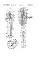
- FIG. 1is a side elevation view of a tool embodying the present invention
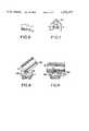
- FIG. 2is a perspective view of the bottom of the tool shown in FIG. 1 illustrated on a larger scale;
- FIG. 3is an enlarged axial sectional view through the upper part of the tool shown in FIG. 1;
- FIG. 4is a side view of the cutting blade shown in FIG. 1, also illustrated on a larger scale;
- FIG. 5is a cross-sectional view taken along the line V--V in FIG. 4;
- FIG. 6is a plan view of the end portion of the holder stirrup displayed in FIG. 1;
- FIG. 7is a side elevational view, on a smaller scale as compared to FIG. 1, of the cable supporting area on a known tool.
- FIGS. 8 and 9are partial side views, partly in section, illustrating the supporting area of the tool embodying the present invention and displayed on a larger scale than FIG. 1.
- FIGS. 1, 2 and 3a replaceable cutting blade 5 is positioned within a housing 18.
- a lever 4is secured to and extends laterally outwardly from the housing 18.
- the lever 4is movable through a slot formed in one end of a handle 17.
- the slotextends transversely of the elongated direction of the handle and is dimensioned so that the housing 18 can be rotated within certain limits within the handle.
- the cutting blade 5 at its opposite end from the cutting edgehas a planar portion or tongue 13, note FIG. 4, which fits in a correspondingly shaped opening 19, note FIG. 3, in the housing 18.
- the exposed length T of the cutting blade extending from the end of the housing 18is adjustable by a knurled adjustment screw 7 threaded into and forming a part of the housing 18.
- a compression spring 10note FIG. 3, which increases the frictional resistance of the threaded connection. Due to the compression spring 10, the adjusted position of the cutting blade remains unchanged even when the housing 18 is rotated relative to the handle 17.
- housing 18is supposed to be in one of its end positions, as determined by the limits formed by the slot 3, and it is held by a torsionally stressed spring 11 extending from the handle 17 into a bore in the opposite end of the housing 18 from the adjustment screw 7.
- One end 11a of the spring 11has an ear, not illustrated, which engages within an axially extending recess 12 in the housing 18.
- the other end 11b of the spring 11is secured within a recess, not illustrated, in the handle 17.
- the spring 11inhibits undesired turning or rotation of the housing 18.
- the axial direction of the recess 12refers to the axial or elongated direction of the handle 17 and the housing 18.
- a holder stirrup 2has a guide portion 2b extending axially into the handle 17.
- the part of the stirrup 2 projecting outwardly from the handle 17is V-shaped with the pointed portion of the V-shaped art centered over the cutting blade 5.
- a tension spring 15 located within the handlebiases the stirrup 2 into the handle.
- Spring 15is secured at one end to a lug extending laterally from the stirrup portion 2b and at its other end it is connected to a retaining pin 14 extending transversely of the axial direction of the handle.
- the pin 14is shown seated within one of two elongated receiving grooves 16a, 16b extending angularly relative to one another and formed in the bottom 17a of the handle 17.
- a bore 16cextends in the axial direction of the handle 17 from the groove 16b. Bore 16c forms a storage space for holding at least one spare cutting blade 5'.
- bore 16cis accessible by displacing the transversely extending pin 14 in the direction indicated by the arrow P from the groove 16b into the other groove 16a. After a spare blade 5' is removed or a new spare blade is inserted into the bore 16c, the pin 14 is displaced back into the groove 16b and serves as a cover for the storage space.
- the free end 2a of the holder stirrup 2is gradually flattened in the thickness direction though its width remains unchanged, providing a wedge-shaped end and not a punctiform end.
- the flattened end 2ais displayed in FIG. 6. Since the end 2a is flattened into something of a wedge-shaped, if needed, it can be used for breaking up the severed part of the insulation.
- the supporting surface surrounding the cutting bladeis in the form of a spherical cap or surface, as exhibited in FIG. 7. With such a surface the cable 30 containing the insulation to be removed has the tendency to roll off on the supporting surface 22.
- the supporting surface surrounding the cutting blade 5is in the form of a central recess 23a extending around the cutting blade 5 on the housing 18 or the adjustable screw 7 forming a part of the housing. Further, the surface radially outwardly of the recess 23a forms a bevelled edge 23b, note FIG. 8, or, alternatively, radially outwardly from the recess, the surronding surface is in the form of a spherical cap such as shown in FIG. 7.
- recess 23ais located within the surface of the adjustment screw 7, that is the end surface of the adjustment screw from which the cutting blade 5 projects.
- Blade 5is locked in the housing 18 so that it cannot rotate or vary the extent to which it projects outwardly from the adjustment screw.
- the opposite end of the bladehas its tongue 13 secured within the opening 19 so that it cannot turn relative to the housing 18.
- Adjustment screw 7has an axially extending cylindrical bore 7a and the central part 5c of the cutting blade, see FIG. 3, is of a circular cross section so that it is reliably guided in all of the rotational positions of the adjustment screw 7 relative to the housing 18.
- the central or cylindrical part 5c of the blade 5 and the bore 7aare dimensioned so that the blade fits closely within the bore.
- the supporting surface formed in the outer end of the adjustment screw 7provides an improved boundary limit for the cable 30 held against the blade 5 by the holder stirrup 2 and prevents the cable from rolling off the supporting surface.
- the tool embodying the present inventionhas the following advantages. As is shown in FIG. 9, when the cutting blade 5, projecting from the adjustment screw 7, penetrates into the insulation layer 30a of the cable 30, a bulge extending outwardly from the core of the cable is formed by the insulation layer and extends into the space in the recess 23a so that there is no increased friction as is present in the known tool, between the cable and the holder stirrup 2.
- the cutting bladeWhen the insulation has been severed the cutting blade may be rotated through 90° about its longitudinal axis and the insulation layer cut up in the axial direction of the cable. When the axial cut reaches its end the cable can be positioned somewhat obliquely relatively to the blade, as is displayed in FIG. 8. This arrangement ensures a cleaner cut through the insulation up to its very end.
- the operative portion of the bladeis kept as narrow as possible, such as illustrated in cross-section in FIG. 5, and is provided with two cutting edges 5a, 5b.
- the cutting blade 5has the shape of a biconvex lens so that the cutting blade at the cutting edges is as narrow as possible. With such an arrangement the blade displaces a small amount of the insulation material and its resistance on cutting the insulation layer is smaller. Because the blade 5 has two cutting edges 5a, 5b, the tool can be turned about the cable 30 in either direction.
- the slot 3extends around the axis of the handle 17 so that the housing 18 can be rotated in the handle through 180°.
- the life of the blade 5is increased, because when one of the cutting edges 5a, 5b becomes blunt, the other cutting edge may be positioned to cut in the preferred direction.
- the tool embodying the present inventionis particularly suitable for removing insulation from relatively large diameter cables, such as in the range of 6 to 30 mm, in principle the tool is also suitable for stripping insulation from other sized cables.
Landscapes
- Removal Of Insulation Or Armoring From Wires Or Cables (AREA)
- Knives (AREA)
Abstract
Description
Claims (11)
Applications Claiming Priority (1)
| Application Number | Priority Date | Filing Date | Title |
|---|---|---|---|
| SE8006042ASE460939B (en) | 1980-08-29 | 1980-08-29 | TOOLS FOR DRAINING CABLE END |
Publications (1)
| Publication Number | Publication Date |
|---|---|
| US4472877Atrue US4472877A (en) | 1984-09-25 |
Family
ID=20341624
Family Applications (1)
| Application Number | Title | Priority Date | Filing Date |
|---|---|---|---|
| US06/330,661Expired - Fee RelatedUS4472877A (en) | 1980-08-29 | 1981-12-14 | Tool for removing insulation from cables |
Country Status (5)
| Country | Link |
|---|---|
| US (1) | US4472877A (en) |
| DE (1) | DE3140193A1 (en) |
| FR (1) | FR2514960B1 (en) |
| GB (1) | GB2108773B (en) |
| SE (1) | SE460939B (en) |
Cited By (18)
| Publication number | Priority date | Publication date | Assignee | Title |
|---|---|---|---|---|
| US5146717A (en)* | 1991-12-03 | 1992-09-15 | Josef Shemesh | Rotating tool |
| US5381601A (en)* | 1992-10-21 | 1995-01-17 | Weidmuller Interface Gmbh & Co. | Insulation stripping apparatus |
| US6073349A (en)* | 1995-09-13 | 2000-06-13 | Liversidge; Barry P. | Wire stripper |
| US6334253B1 (en)* | 2000-08-28 | 2002-01-01 | Yin-Ho Cheng | Adjustable wire stripper |
| EP1117163A3 (en)* | 2000-01-12 | 2002-02-27 | P. W. Weidling & Sohn GmbH & Co. KG | Cable knife |
| US6510611B2 (en) | 1999-10-19 | 2003-01-28 | Tyco Electronics Corporation | Cable jacket stripping tool |
| US20030110636A1 (en)* | 2001-12-19 | 2003-06-19 | Johan Tapper | Cable-stripping tool |
| US20030110638A1 (en)* | 2001-12-19 | 2003-06-19 | Johan Tapper | Cable-stripping tool |
| US7563124B1 (en)* | 2008-05-21 | 2009-07-21 | The United States Of America As Represented By The Secretary Of The Air Force | Harvesting power from low-voltage overhead power cables |
| US20090255125A1 (en)* | 2008-04-15 | 2009-10-15 | Hager Gregory L | Cable sheath splitter |
| DE112011100281T5 (en) | 2010-01-19 | 2012-11-08 | Tyco Thermal Controls, Llc | Hand tool for cutting and slitting |
| US20130152758A1 (en)* | 2011-12-16 | 2013-06-20 | Sumitomo Electric Lightwave Corp. | Entry tool and methods for use for tubes or cables |
| US20130333222A1 (en)* | 2012-06-14 | 2013-12-19 | Stanley Works (Europe) Gmbh | Manual cable stripping tool |
| US20170054280A1 (en)* | 2015-08-21 | 2017-02-23 | Greenlee Textron Inc. | Cable stripping tool and bi-directional cutting blade |
| US10418796B2 (en) | 2016-03-27 | 2019-09-17 | Southwire Company, Llc | Cable stripper |
| US20220231491A1 (en)* | 2019-05-06 | 2022-07-21 | Rennsteig Werkzeuge Gmbh | Insulating-stripping tool designed as a hand tool, cutting part for an insulation-stripping tool and method for stripping a cable |
| US20220357510A1 (en)* | 2021-05-07 | 2022-11-10 | Ripley Tools, Llc | Shaving tool with upright handle |
| US11527874B1 (en) | 2022-06-28 | 2022-12-13 | Araspeed Tool Company LLC | Wire tool for stripping and terminating electrical wires and methods of using the same |
Families Citing this family (10)
| Publication number | Priority date | Publication date | Assignee | Title |
|---|---|---|---|---|
| US4451948A (en)* | 1982-03-30 | 1984-06-05 | Bell Telephone Laboratories, Incorporated | Wire stripping tool |
| GB2133226B (en)* | 1983-01-07 | 1986-07-02 | Zdzislaw Bieganski | Cable stripper |
| SE8304627D0 (en) | 1983-08-26 | 1983-08-26 | Weidmueller C A Gmbh Co | ABISOLIATED FOR COAXIAL CABLE |
| GB2192759A (en)* | 1986-07-16 | 1988-01-20 | Michael Horace Mcdermott | Insulation stripper |
| GB2229324A (en)* | 1989-01-26 | 1990-09-19 | Barry Peter Liversidge | Wire stripping tool |
| DE4204141C1 (en)* | 1992-02-12 | 1993-06-17 | Weidmueller Interface Gmbh & Co, 4930 Detmold, De | |
| GB2330699B (en)* | 1997-08-22 | 1999-09-22 | Derrick Andrew Cutting | Electrical cable insulation cutter |
| DE102007032399B3 (en)* | 2007-07-10 | 2008-09-11 | Rennsteig Werkzeuge Gmbh | Kabelabmantelwerkzeug |
| DE102015104906B3 (en)* | 2015-03-30 | 2016-08-04 | Krampe Immobilien Gmbh & Co. Kg | Cable knife with two blades |
| DE102018115487A1 (en) | 2018-06-27 | 2020-01-02 | Weidmüller Interface GmbH & Co. KG | Tool for stripping a cable |
Citations (9)
| Publication number | Priority date | Publication date | Assignee | Title |
|---|---|---|---|---|
| US98294A (en)* | 1869-12-28 | Improved tube-cutter | ||
| US1979487A (en)* | 1932-10-21 | 1934-11-06 | Roeblings John A Sons Co | Cable cutting and stripping tool |
| US2141002A (en)* | 1936-12-24 | 1938-12-20 | Victor C Huff | Cable stripper |
| GB555009A (en)* | 1941-02-05 | 1943-07-29 | Avaror Ab | Improvements in tools for cutting the protective covering of conductor cables |
| US2830366A (en)* | 1955-08-11 | 1958-04-15 | Ernest F Chisena | Cutting implements for electric cables |
| US3483617A (en)* | 1966-10-28 | 1969-12-16 | Josef Krampe | Tool for cutting and stripping cable |
| US3665603A (en)* | 1969-12-11 | 1972-05-30 | Robert A Bilbrey | Cable stripping tool |
| US3881249A (en)* | 1974-06-05 | 1975-05-06 | Ideal Ind | Cable stripper |
| US3946487A (en)* | 1973-04-26 | 1976-03-30 | Zdzislaw Bieganski | Tools for cutting |
Family Cites Families (4)
| Publication number | Priority date | Publication date | Assignee | Title |
|---|---|---|---|---|
| US2649654A (en)* | 1944-10-26 | 1953-08-25 | Anthony Carta | Slitting device for wire insulation or the like |
| DE1690162B2 (en)* | 1967-01-10 | 1973-01-04 | Schoerken & Co, 5600 Wuppertalronsdorf | Cable stripping tool |
| DE1665498B1 (en)* | 1967-11-18 | 1970-09-03 | Rittmeyer Feintechnik | Stripping tool for electrical cables |
| US3826001A (en)* | 1973-04-30 | 1974-07-30 | Speed Syst Inc | Cable stripping tool |
- 1980
- 1980-08-29SESE8006042Apatent/SE460939B/ennot_activeIP Right Cessation
- 1981
- 1981-10-09DEDE19813140193patent/DE3140193A1/ennot_activeCeased
- 1981-10-13GBGB08130869Apatent/GB2108773B/ennot_activeExpired
- 1981-10-16FRFR8119484Apatent/FR2514960B1/ennot_activeExpired
- 1981-12-14USUS06/330,661patent/US4472877A/ennot_activeExpired - Fee Related
Patent Citations (9)
| Publication number | Priority date | Publication date | Assignee | Title |
|---|---|---|---|---|
| US98294A (en)* | 1869-12-28 | Improved tube-cutter | ||
| US1979487A (en)* | 1932-10-21 | 1934-11-06 | Roeblings John A Sons Co | Cable cutting and stripping tool |
| US2141002A (en)* | 1936-12-24 | 1938-12-20 | Victor C Huff | Cable stripper |
| GB555009A (en)* | 1941-02-05 | 1943-07-29 | Avaror Ab | Improvements in tools for cutting the protective covering of conductor cables |
| US2830366A (en)* | 1955-08-11 | 1958-04-15 | Ernest F Chisena | Cutting implements for electric cables |
| US3483617A (en)* | 1966-10-28 | 1969-12-16 | Josef Krampe | Tool for cutting and stripping cable |
| US3665603A (en)* | 1969-12-11 | 1972-05-30 | Robert A Bilbrey | Cable stripping tool |
| US3946487A (en)* | 1973-04-26 | 1976-03-30 | Zdzislaw Bieganski | Tools for cutting |
| US3881249A (en)* | 1974-06-05 | 1975-05-06 | Ideal Ind | Cable stripper |
Cited By (26)
| Publication number | Priority date | Publication date | Assignee | Title |
|---|---|---|---|---|
| US5146717A (en)* | 1991-12-03 | 1992-09-15 | Josef Shemesh | Rotating tool |
| EP0546738A1 (en)* | 1991-12-03 | 1993-06-16 | Josef Shemesh | Rotating tool |
| US5381601A (en)* | 1992-10-21 | 1995-01-17 | Weidmuller Interface Gmbh & Co. | Insulation stripping apparatus |
| US6073349A (en)* | 1995-09-13 | 2000-06-13 | Liversidge; Barry P. | Wire stripper |
| US6510611B2 (en) | 1999-10-19 | 2003-01-28 | Tyco Electronics Corporation | Cable jacket stripping tool |
| EP1117163A3 (en)* | 2000-01-12 | 2002-02-27 | P. W. Weidling & Sohn GmbH & Co. KG | Cable knife |
| US6334253B1 (en)* | 2000-08-28 | 2002-01-01 | Yin-Ho Cheng | Adjustable wire stripper |
| US20030110636A1 (en)* | 2001-12-19 | 2003-06-19 | Johan Tapper | Cable-stripping tool |
| US20030110638A1 (en)* | 2001-12-19 | 2003-06-19 | Johan Tapper | Cable-stripping tool |
| US6802125B2 (en)* | 2001-12-19 | 2004-10-12 | Pressmaster Ab | Cable-stripping tool |
| US6910275B2 (en)* | 2001-12-19 | 2005-06-28 | Pressmaster Ab | Cable-stripping tool |
| US20090255125A1 (en)* | 2008-04-15 | 2009-10-15 | Hager Gregory L | Cable sheath splitter |
| US7913394B2 (en)* | 2008-04-15 | 2011-03-29 | Hager Gregory L | Cable sheath splitter |
| US7563124B1 (en)* | 2008-05-21 | 2009-07-21 | The United States Of America As Represented By The Secretary Of The Air Force | Harvesting power from low-voltage overhead power cables |
| DE112011100281T5 (en) | 2010-01-19 | 2012-11-08 | Tyco Thermal Controls, Llc | Hand tool for cutting and slitting |
| US20130152758A1 (en)* | 2011-12-16 | 2013-06-20 | Sumitomo Electric Lightwave Corp. | Entry tool and methods for use for tubes or cables |
| US9184575B2 (en)* | 2011-12-16 | 2015-11-10 | Sumitomo Electric Lightwave Corp. | Entry tool and methods for use for tubes or cables |
| US20130333222A1 (en)* | 2012-06-14 | 2013-12-19 | Stanley Works (Europe) Gmbh | Manual cable stripping tool |
| US20170054280A1 (en)* | 2015-08-21 | 2017-02-23 | Greenlee Textron Inc. | Cable stripping tool and bi-directional cutting blade |
| US10763651B2 (en)* | 2015-08-21 | 2020-09-01 | Greenlee Tools, Inc. | Cable stripping tool and bi-directional cutting blade |
| US10418796B2 (en) | 2016-03-27 | 2019-09-17 | Southwire Company, Llc | Cable stripper |
| US20220231491A1 (en)* | 2019-05-06 | 2022-07-21 | Rennsteig Werkzeuge Gmbh | Insulating-stripping tool designed as a hand tool, cutting part for an insulation-stripping tool and method for stripping a cable |
| US12300980B2 (en)* | 2019-05-06 | 2025-05-13 | Rennsteig Werkzeuge Gmbh | Insulating-stripping tool designed as a hand tool, cutting part for an insulation-stripping tool and method for stripping a cable |
| US20220357510A1 (en)* | 2021-05-07 | 2022-11-10 | Ripley Tools, Llc | Shaving tool with upright handle |
| US12355221B2 (en)* | 2021-05-07 | 2025-07-08 | Hubbell Power Systems, Inc. | Shaving tool with upright handle |
| US11527874B1 (en) | 2022-06-28 | 2022-12-13 | Araspeed Tool Company LLC | Wire tool for stripping and terminating electrical wires and methods of using the same |
Also Published As
| Publication number | Publication date |
|---|---|
| GB2108773A (en) | 1983-05-18 |
| GB2108773B (en) | 1985-07-24 |
| FR2514960A1 (en) | 1983-04-22 |
| FR2514960B1 (en) | 1985-12-13 |
| SE8006042L (en) | 1982-03-01 |
| DE3140193A1 (en) | 1983-04-28 |
| SE460939B (en) | 1989-12-04 |
Similar Documents
| Publication | Publication Date | Title |
|---|---|---|
| US4472877A (en) | Tool for removing insulation from cables | |
| US4955137A (en) | Mechanism for adjusting depth of cut on wire and cable jackets | |
| US7503119B2 (en) | Tool for stripping cables | |
| US20090100681A1 (en) | Coaxial cable stripping tool with adjustable strip stop | |
| PL136399B1 (en) | Single-bladed reamer | |
| US4395928A (en) | Hand tool for stripping insulation from wire | |
| US3091031A (en) | Cable slitting tool | |
| US4693542A (en) | Electrical screw connection | |
| US4426778A (en) | Device for stripping wire and cable | |
| JPH0135567B2 (en) | ||
| US6427331B1 (en) | Slitting and shaving tool for messengered cable | |
| US5345681A (en) | Tool for stripping a conductor | |
| US4104791A (en) | Stripper for coated wires | |
| US4796877A (en) | Workpiece holder and saw guide device | |
| US2096472A (en) | Blade anchoring wedge | |
| US20060163280A1 (en) | Dispensing tube opener | |
| USRE30342E (en) | Wire stripper having replaceable blades | |
| US3377891A (en) | Cable insulation removing tool | |
| US2778105A (en) | Cutter for the insulation of cables | |
| US6925920B1 (en) | Knife holder and knife for a microtome | |
| US5829141A (en) | Device for cutting insulation | |
| US4734982A (en) | Plastic-pipe cutter | |
| JPS61293107A (en) | Stripping tool | |
| CA1124045A (en) | Wrapping of electrically conductive wires | |
| US4777712A (en) | Apparatus for stripping the insulation from cables |
Legal Events
| Date | Code | Title | Description |
|---|---|---|---|
| AS | Assignment | Owner name:C.A. WEIDMULLER GMBH & CO. P.O. BOX 950, D-4930 DE Free format text:ASSIGNMENT OF ASSIGNORS INTEREST.;ASSIGNORS:UNDIN, HANS;WIENER, HANS;REEL/FRAME:003968/0791 Effective date:19811207 | |
| FEPP | Fee payment procedure | Free format text:PAYOR NUMBER ASSIGNED (ORIGINAL EVENT CODE: ASPN); ENTITY STATUS OF PATENT OWNER: LARGE ENTITY | |
| FPAY | Fee payment | Year of fee payment:4 | |
| FPAY | Fee payment | Year of fee payment:8 | |
| AS | Assignment | Owner name:WEIDMULLER INTERFACE GMBH & CO., GERMANY Free format text:CHANGE OF NAME;ASSIGNOR:C. A. WEIDMULLER GMBH & CO.;REEL/FRAME:006599/0619 Effective date:19920123 Owner name:WEIDMULLER INC., VIRGINIA Free format text:ASSIGNMENT OF 50% INTEREST;ASSIGNOR:WEIDMULLER INTERFACE GMBH & CO.;REEL/FRAME:006599/0623 Effective date:19930512 | |
| AS | Assignment | Owner name:WEIDMULLER INC., PALADIN TOOLS, CALIFORNIA Free format text:ASSIGNS 50% INTEREST;ASSIGNOR:WEIDMULLER INTERFACE GMBH & CO.;REEL/FRAME:006705/0810 Effective date:19930512 | |
| REMI | Maintenance fee reminder mailed | ||
| LAPS | Lapse for failure to pay maintenance fees | ||
| FP | Lapsed due to failure to pay maintenance fee | Effective date:19960925 | |
| STCH | Information on status: patent discontinuation | Free format text:PATENT EXPIRED DUE TO NONPAYMENT OF MAINTENANCE FEES UNDER 37 CFR 1.362 |