US4472099A - Releasable locking device - Google Patents
Releasable locking deviceDownload PDFInfo
- Publication number
- US4472099A US4472099AUS06/278,168US27816881AUS4472099AUS 4472099 AUS4472099 AUS 4472099AUS 27816881 AUS27816881 AUS 27816881AUS 4472099 AUS4472099 AUS 4472099A
- Authority
- US
- United States
- Prior art keywords
- carriage
- piston
- cylinder
- unit
- elongated
- Prior art date
- Legal status (The legal status is an assumption and is not a legal conclusion. Google has not performed a legal analysis and makes no representation as to the accuracy of the status listed.)
- Expired - Lifetime
Links
- 230000000694effectsEffects0.000claimsabstractdescription3
- 239000012530fluidSubstances0.000claimsdescription2
- 230000000881depressing effectEffects0.000claims1
- 238000010276constructionMethods0.000description2
- 230000000994depressogenic effectEffects0.000description2
- 230000014759maintenance of locationEffects0.000description2
- 238000005086pumpingMethods0.000description2
- 230000007257malfunctionEffects0.000description1
- 125000006850spacer groupChemical group0.000description1
- 238000003466weldingMethods0.000description1
Images

Classifications
- B—PERFORMING OPERATIONS; TRANSPORTING
- B65—CONVEYING; PACKING; STORING; HANDLING THIN OR FILAMENTARY MATERIAL
- B65G—TRANSPORT OR STORAGE DEVICES, e.g. CONVEYORS FOR LOADING OR TIPPING, SHOP CONVEYOR SYSTEMS OR PNEUMATIC TUBE CONVEYORS
- B65G69/00—Auxiliary measures taken, or devices used, in connection with loading or unloading
- B65G69/003—Restraining movement of a vehicle at a loading station using means not being part of the vehicle
- Y—GENERAL TAGGING OF NEW TECHNOLOGICAL DEVELOPMENTS; GENERAL TAGGING OF CROSS-SECTIONAL TECHNOLOGIES SPANNING OVER SEVERAL SECTIONS OF THE IPC; TECHNICAL SUBJECTS COVERED BY FORMER USPC CROSS-REFERENCE ART COLLECTIONS [XRACs] AND DIGESTS
- Y10—TECHNICAL SUBJECTS COVERED BY FORMER USPC
- Y10T—TECHNICAL SUBJECTS COVERED BY FORMER US CLASSIFICATION
- Y10T292/00—Closure fasteners
- Y10T292/08—Bolts
- Y10T292/0911—Hooked end
- Y10T292/0945—Operating means
- Y10T292/0949—Lever
Definitions
- prior locking deviceswere of costly and complex design; were highly susceptible to malfunction particularly when exposed to various climatic conditions; were difficult and expensive to install on a loading dock; and/or they restricted or interfered with the full use of the loading dock.
- a locking devicefor releasably securing a parked vehicle to an adjacent structure such as a loading dock or the like.
- the deviceincludes a pivotally mounted elongated unit which is attached to the adjacent structure.
- the unitis adapted to move between a vehicle-interlocking operative mode and a vehicle-release inoperative mode. Movement of the elongated unit from an inoperative mode to an operative mode is effected by a hydraulic power means.
- the power meansincludes a manually operable pump means remotely disposed relative to the elongated unit, and an elongated flexible pressure-transmitting means having one end portion thereof operatively connected to the elongated unit and the other end portion connected to the pump means.
- FIG. 1is a fragmentary side elevational view of one form of the improved locking device shown installed on the front wall of a conventional loading dock, and with the elongated unit thereof disposed in an inoperative mode.
- FIG. 2is similar to FIG. 1 but with the elongated unit disposed in an operative mode; the unit and the carriage on which it is mounted are also shown in phantom lines in a downwardly depressed position.
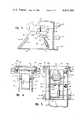
- FIG. 3is an enlarged fragmentary side view of the device of FIG. 2, but with a portion of the carriage removed so as to expose various components substantially concealed within the carriage.
- FIG. 4is an enlarged fragmentary top view of the device of FIG. 2.
- FIG. 5is an enlarged sectional view taken along line 5--5 of FIG. 2.
- FIGS. 1 and 2one form of the improved locking device 10 is shown mounted on the front vertical wall W of a conventional loading dock D.
- the wall Wextends from a roadway R, which supports the parked vehicle, not shown, to an elevated, horizontally disposed platform surface P.
- the height of surface Papproximates the height of the vehicle bed, the latter supporting the products to be loaded onto or unloaded from the vehicle. Because of this height relationship, fork-lift trucks, dollies, and the like may be conveniently utilized to assist in the loading and unloading operations.
- Device 10is secured to wall W by a mounting bracket or member 11 which is anchored thereto by any suitable means (e.g. anchor bolts). Mounted on bracket 11 and projecting outwardly therefrom is a carriage 12. The carriage is mounted so as to be capable of limited vertical relative movement as will be described more fully hereinafter.
- Carriage 12 in the illustrated embodimentincludes a pair of spaced, substantially parallel vertical plate members 14, 15 which project transversely from the bracket 11. Shaft A is supported by plate members 14, 15 and extends therebetween. The vertical marginal portion of the members 14, 15, adjacent bracket 11, are interconnected by a web section 16.
- the opposite, or outer, marginal portion of members 14, 15are vertically inclined upwardly toward the wall W and form a cam CC which is adapted to be engaged by a conventional IC bar depending from the rear of the vehicle, when the latter is backed into a parked position with respect to the loading dock D.
- cam CCcam CC
- the carriage 14 and associated components to be hereinafter identifiedwill in most instances move downwardly from its normal elevated rest position, as seen more clearly in FIG. 2.
- the carriage 14assumes its normal rest position by reason of a pair of heavy duty springs 17 which engage a pair of lugs 18 affixed to corresponding lower portions of plate members 14, 15.
- the upper end of each spring 17is anchored to a lug 19 extending laterally from the upper end of bracket 11.
- each armhas the ends 20a-b, 21a-b thereof projecting laterally a like amount beyond the plane of the adjacent plate member.
- Corresponding arm endsare disposed within suitable elongated vertically extending guideways 22, 23 formed along opposite side marginal portions of the bracket 11.
- each guideway 22, 23is substantially channel-shaped with the open elongated sides of the channels being opposed to one another.
- suitable rollersmay be carried on the arm ends.
- the arms 20, 21are vertically spaced relative to one another, thereby providing added stability to the carriage, as the latter moves vertically relative to bracket 11.
- a second shaft BPositioned beneath the horizontally disposed shaft A on which the elongated unit 13 is mounted, and spanning the distance between the plate members 14, 15 is a second shaft B.
- the ends of shaft Bare preferably journalled in the plate members.
- a lever 24Keyed to shaft B is a lever 24 having a protruding end 24a slidably engaging the underside of unit 13 at a substantial distance from shaft A.
- the end 24a of the leveris preferably rounded.
- a link 25to which the upper exposed end of a piston 26 is pivotally connected.
- the opposite end of piston 26is concealed within an hydraulic cylinder 27.
- the lower end of cylinder 27is pivotally connected to a third shaft C, the latter being supported by and spanning the distance between plate members 14, 15, see FIGS. 3 and 5.
- piston 26is a single acting piston; that is to say it is driven by hydraulic pressure in only one direction (e.g., upwardly) so that link 25 will pivot in a clockwise direction about the axis of shaft B. Because both link 25 and lever 24 are keyed to shaft B, lever 24 will also move in a clockwise direction and apply upwardly pushing pressure on the underside of unit 13 thereby causing the latter to assume its operative mode II. Once hydraulic pressure within cylinder 27 is relieved, the weight of unit 13 will cause the latter to move to a depending inoperative mode I.
- a manually operated pump assembly 28is provided which is preferably located at a remote location relative to the carriage 14.
- the type of pump assemblymay vary considerably, but in the illustrated embodiment, it is of a conventional foot activated type, wherein a foot pumping pedal 30 is provided which is connected to a drive piston 31, the latter coacting with a cylinder 32 formed in the pump base 33. Connected to the pump base and communicating with the lower end of cylinder 32 is one end of a section of flexible tubing T.
- the opposite end of the tubingextends through a suitable opening formed in the carriage plate member 14 and is connected to the cylinder 27 adjacent the pivotally connected end of the latter.
- a suitable grommetmay be provided in the plate member opening so as to enable the tubing T to readily slide endwise through the opening as the carriage moves vertically and as the cylinder 27 pivots about shaft C. There should be sufficient slack provided in the length of the tubing to permit such relative movement between the tubing and the plate member opening.
- the pumpshould be provided with a suitable release valve which may be activated by a secondary foot pedal 34.
- pedal 34When pedal 34 is depressed, the hydraulic pressure confined within cylinder 27 will be released and the hydraulic fluid will flow back into the pump cylinder 32.
- the aforedescribed operation of the pump 30is well understood in the pump art.
- the pump 30may be located inside a security door, whereby when the door is secured in a closed position, the pump cannot be operated by one outside the closed door. Thus, the incidence of unauthorized use or vandalism are markedly reduced.
- the location of the pump 30 relative to carriage 14is limited only by the length of the tubing T.
- the hook-like unitis formed into two sections which are connected to one another by a suitable shear pin 35, see FIGS. 3 and 4.
- the lower portions of the cam-forming marginal portions of plate members 14, 15 of carriage 12are interconnected by a transversely extending spacer 36.
- the plate membersare maintained in proper parallel spaced relation by the space 36.
- the IC bar of the latterwill be captured behind the upwardly extending distal end of unit 13. While the parked vehicle is being loaded, the added weight being supported by the vehicle bed will exert a downward force on the unit which may be compensated for by the springs 17 and thus, result in the carriage 12 being moved downwardly the required amount and avoid damaging stresses and strains being imposed on the carriage and the hook-like unit.
- an improved locking devicewhich is of simple, inexpensive construction and one capable of being safely operated under widely varying climatic conditions.
- the improved deviceis capable of accommodating a wide variety of vehicles.
Landscapes
- Engineering & Computer Science (AREA)
- Mechanical Engineering (AREA)
- Lock And Its Accessories (AREA)
Abstract
Description
Claims (2)
Priority Applications (1)
| Application Number | Priority Date | Filing Date | Title |
|---|---|---|---|
| US06/278,168US4472099A (en) | 1981-06-29 | 1981-06-29 | Releasable locking device |
Applications Claiming Priority (1)
| Application Number | Priority Date | Filing Date | Title |
|---|---|---|---|
| US06/278,168US4472099A (en) | 1981-06-29 | 1981-06-29 | Releasable locking device |
Publications (1)
| Publication Number | Publication Date |
|---|---|
| US4472099Atrue US4472099A (en) | 1984-09-18 |
Family
ID=23063950
Family Applications (1)
| Application Number | Title | Priority Date | Filing Date |
|---|---|---|---|
| US06/278,168Expired - LifetimeUS4472099A (en) | 1981-06-29 | 1981-06-29 | Releasable locking device |
Country Status (1)
| Country | Link |
|---|---|
| US (1) | US4472099A (en) |
Cited By (69)
| Publication number | Priority date | Publication date | Assignee | Title |
|---|---|---|---|---|
| US4555211A (en)* | 1982-06-11 | 1985-11-26 | Metz Donald L | Truck locking device |
| US4560315A (en)* | 1984-07-11 | 1985-12-24 | Rite-Hite Corporation | Vehicle restraint |
| US4643624A (en)* | 1985-06-11 | 1987-02-17 | Murphree Pat D | Guide means for stabilizing pipe strings |
| US4695216A (en)* | 1986-05-14 | 1987-09-22 | Kelley Company, Inc. | Vehicle restraint |
| US4728242A (en)* | 1986-04-14 | 1988-03-01 | Kelley Company Inc. | Vehicle restraint having downwardly facing hook |
| US4744121A (en)* | 1987-02-20 | 1988-05-17 | Rite-Hite Corporation | Loading dock and hydraulic system therefor |
| US4765792A (en)* | 1987-03-23 | 1988-08-23 | Autoquip Corporation | Surface mounted truck leveler |
| US4767254A (en)* | 1986-04-21 | 1988-08-30 | Kelley Company Inc. | Vehicle restraint having an upwardly biased restraining member |
| US4815918A (en)* | 1987-08-21 | 1989-03-28 | Kelley Company, Inc. | Vehicle restraint having a snubbing restraining member |
| US4830563A (en)* | 1987-06-09 | 1989-05-16 | Vestil Manufacturing Company | Multi-condition responsive vehicle restraining apparatus |
| USRE32968E (en)* | 1984-07-11 | 1989-06-27 | Abon Corporation | Vehicle restraint |
| US4861217A (en)* | 1987-02-17 | 1989-08-29 | Kelley Company, Inc. | Vehicle restraint using both linear and pivotal movement |
| US4865508A (en)* | 1987-05-21 | 1989-09-12 | Kelley Company Inc. | Vehicle restraint |
| US4887954A (en)* | 1989-03-09 | 1989-12-19 | Air-Lec Industries, Inc. | Vehicle restraint |
| US4915568A (en)* | 1988-02-24 | 1990-04-10 | West David E | Vehicle restraining apparatus |
| US4938647A (en)* | 1989-09-21 | 1990-07-03 | Kelley Company Inc. | Truck actuated vehicle restraint having a pivotable slide |
| US4938648A (en)* | 1988-08-31 | 1990-07-03 | General Motors Corporation | Shipping dock hook |
| US4946330A (en)* | 1988-09-14 | 1990-08-07 | Pentalift Equipment Corporation | Truck restraint |
| US4963068A (en)* | 1989-01-23 | 1990-10-16 | Systems, Inc. | Trailer restraint |
| US4973213A (en)* | 1989-09-21 | 1990-11-27 | Kelley Company Inc. | Truck actuated vehicle restraint having a pivotable inclined surface |
| EP0356073A3 (en)* | 1988-08-16 | 1991-01-23 | Serco Corporation | Vehicle restraint |
| US5026242A (en)* | 1990-02-21 | 1991-06-25 | Serco Corporation | Automatic vehicle restraint |
| US5071306A (en)* | 1988-08-16 | 1991-12-10 | Serco Corporation | Vehicle restraint |
| US5120181A (en)* | 1990-01-18 | 1992-06-09 | The Serco Corporation | Vehicle restraint |
| WO1993003989A1 (en)* | 1991-08-13 | 1993-03-04 | Rite-Hite Corporation | A releasable locking device |
| US5224812A (en)* | 1991-08-22 | 1993-07-06 | Delaware Capital Formation, Inc. | Transport cart |
| US5259718A (en)* | 1990-01-18 | 1993-11-09 | The Serco Corporation | Vehicle restraint |
| US5348437A (en)* | 1993-05-17 | 1994-09-20 | Overhead Door Corporation | Vehicle restraining apparatus |
| US5375965A (en)* | 1993-01-25 | 1994-12-27 | Rite-Hite Corporation | Vehicle restraining device |
| US5452489A (en)* | 1993-09-21 | 1995-09-26 | Systems, Inc. | Dock leveler with automatic end barrier |
| US5457838A (en)* | 1993-09-21 | 1995-10-17 | Systems, Inc. | Extendible dock leveler |
| US5553987A (en)* | 1994-03-07 | 1996-09-10 | Rite-Hite Corporation | Truck activated wheel chocking device |
| US5582498A (en)* | 1994-10-21 | 1996-12-10 | Rite-Hite Corporation | Wheel activated vehicle restraint |
| US5683219A (en)* | 1996-06-07 | 1997-11-04 | Pioneer Manufacturing, Inc. | Mechanical truck restraint |
| US5702223A (en)* | 1993-12-23 | 1997-12-30 | Rite-Hite Corporation | Vehicle restraint |
| US5762459A (en)* | 1994-10-21 | 1998-06-09 | Rite-Hite Corporation | Wheel-activated vehicle restraint system |
| US5882167A (en)* | 1997-04-23 | 1999-03-16 | Rite-Hite Holding Corporation | Locking mechanism for a vehicle restraint |
| US6106212A (en)* | 1998-10-26 | 2000-08-22 | Rite-Hite Holding Corporation | Power-up vehicle restraint |
| US6113337A (en)* | 1998-10-01 | 2000-09-05 | Kelley Company, Inc. | Vehicle restraint |
| US6116839A (en)* | 1998-05-27 | 2000-09-12 | Rite-Hite Holding Corporation | Slope extension for vehicle restraints |
| US6190109B1 (en) | 1998-06-04 | 2001-02-20 | Rite-Hite Holding Company | Restraining member with recessed shank for a vehicle restraint |
| US6371714B1 (en)* | 1998-03-17 | 2002-04-16 | Kelley Company, Inc. | Vehicle restraint and method for modifying the same |
| US6439823B1 (en)* | 2000-10-26 | 2002-08-27 | Pro-Qual Inc. | Vehicle restraint device |
| US20030170097A1 (en)* | 2002-01-31 | 2003-09-11 | Paul Pedersen | Truck restraint |
| US6773221B2 (en) | 2001-07-05 | 2004-08-10 | Rite-Hite Holding Corporation | Positive locking mechanism for a wheel-activated vehicle restraint |
| US20050169732A1 (en)* | 2003-12-22 | 2005-08-04 | Matt Sveum | Brace system and method for a vehicle at a loading dock |
| US20050196255A1 (en)* | 2003-12-22 | 2005-09-08 | Matt Sveum | Yieldable brace for a vehicle at a loading dock |
| US20060045678A1 (en)* | 2004-08-11 | 2006-03-02 | Jonathan Andersen | Hydraulic vehicle restraint providing horizontal and vertical spring float with a mechanical hard travel limit |
| US20070248440A1 (en)* | 2003-12-22 | 2007-10-25 | Rite-Hite Holding Corporation | Yieldable brace for a vehicle at a loading dock |
| US20090026022A1 (en)* | 2007-07-25 | 2009-01-29 | Rite-Hite Holding Corporation | Wheel chock system |
| US20090223764A1 (en)* | 2008-03-04 | 2009-09-10 | Jonathan Andersen | Restraining arms for wheel chocks |
| US7914042B2 (en) | 2008-05-13 | 2011-03-29 | Rite-Hite Holding Corporation | Support frame vehicle restraints |
| US8006811B2 (en) | 2007-09-07 | 2011-08-30 | Rite-Hite Holding Corporation | Loading dock wheel restraint comprising a flexible elongate member |
| US8286757B2 (en) | 2010-07-09 | 2012-10-16 | Rite-Hite Holding Corporation | Wheel chock system |
| US9145273B2 (en) | 2011-07-13 | 2015-09-29 | Rite-Hite Holding Corporation | Vehicle restraints with stop mechanisms |
| US9174811B2 (en) | 2012-09-05 | 2015-11-03 | Rite-Hite Holding Corporation | Vehicle restraints with rotating and translating barriers |
| US9227799B2 (en) | 2012-08-30 | 2016-01-05 | Rite-Hite Holding Corporation | Vehicle restraints with anti-rotation features |
| US9272854B2 (en) | 2014-02-06 | 2016-03-01 | Rite-Hite Holding Corporation | Vehicle restraints with activated catches |
| US9586771B2 (en) | 2014-01-29 | 2017-03-07 | Rite-Hite Holding Corporation | Vehicle restraints with underside catches |
| US9751702B1 (en) | 2016-06-06 | 2017-09-05 | ASSA ABLOY Entrance Systems, Inc. | Wheel chock systems |
| US20190009999A1 (en)* | 2017-06-28 | 2019-01-10 | Systems, LLC | Dock Restraint Hook and Control Systems |
| US10329104B2 (en) | 2016-04-04 | 2019-06-25 | Assa Abloy Entrance Systems Ab | Vehicle restraint |
| WO2019232055A1 (en)* | 2018-05-29 | 2019-12-05 | Rite-Hite Holding Corporation | Vehicle restraints with a barrier having rotational and translational motion |
| US10569978B2 (en) | 2018-04-27 | 2020-02-25 | Nordock, Inc. | Trailer restraint with auxiliary securing/locking mechanism |
| WO2020165426A1 (en) | 2019-02-15 | 2020-08-20 | Assa Abloy Entrance Systems Ab | Vehicle restraint |
| US10781062B2 (en) | 2015-11-24 | 2020-09-22 | Systems, LLC | Vehicle restraint system |
| US10906759B2 (en) | 2017-06-28 | 2021-02-02 | Systems, LLC | Loading dock vehicle restraint system |
| US11618642B2 (en) | 2020-08-20 | 2023-04-04 | Assa Abloy Entrance Systems Ab | Vehicle restraint systems and methods |
| WO2024156707A1 (en) | 2023-01-27 | 2024-08-02 | Assa Abloy Entrance Systems Ab | Vehicle restraint |
Citations (6)
| Publication number | Priority date | Publication date | Assignee | Title |
|---|---|---|---|---|
| US1342465A (en)* | 1919-09-19 | 1920-06-08 | Schneider Peter | Car-door lock |
| US2237192A (en)* | 1938-11-17 | 1941-04-01 | Irving H Minkow | Fluid container cap lock |
| US3884056A (en)* | 1973-10-05 | 1975-05-20 | Vern A East | Lock for sliding doors |
| US3944017A (en)* | 1974-12-23 | 1976-03-16 | Ford Motor Company | Suspension for truck cab |
| US4264259A (en)* | 1979-09-06 | 1981-04-28 | Rite-Hite Corporation | Releasable locking device |
| US4282621A (en)* | 1978-12-11 | 1981-08-11 | Rite-Hite Corporation | Releasable locking device |
- 1981
- 1981-06-29USUS06/278,168patent/US4472099A/ennot_activeExpired - Lifetime
Patent Citations (6)
| Publication number | Priority date | Publication date | Assignee | Title |
|---|---|---|---|---|
| US1342465A (en)* | 1919-09-19 | 1920-06-08 | Schneider Peter | Car-door lock |
| US2237192A (en)* | 1938-11-17 | 1941-04-01 | Irving H Minkow | Fluid container cap lock |
| US3884056A (en)* | 1973-10-05 | 1975-05-20 | Vern A East | Lock for sliding doors |
| US3944017A (en)* | 1974-12-23 | 1976-03-16 | Ford Motor Company | Suspension for truck cab |
| US4282621A (en)* | 1978-12-11 | 1981-08-11 | Rite-Hite Corporation | Releasable locking device |
| US4264259A (en)* | 1979-09-06 | 1981-04-28 | Rite-Hite Corporation | Releasable locking device |
Cited By (95)
| Publication number | Priority date | Publication date | Assignee | Title |
|---|---|---|---|---|
| US4555211A (en)* | 1982-06-11 | 1985-11-26 | Metz Donald L | Truck locking device |
| USRE32968E (en)* | 1984-07-11 | 1989-06-27 | Abon Corporation | Vehicle restraint |
| US4560315A (en)* | 1984-07-11 | 1985-12-24 | Rite-Hite Corporation | Vehicle restraint |
| US4643624A (en)* | 1985-06-11 | 1987-02-17 | Murphree Pat D | Guide means for stabilizing pipe strings |
| US4728242A (en)* | 1986-04-14 | 1988-03-01 | Kelley Company Inc. | Vehicle restraint having downwardly facing hook |
| US4767254A (en)* | 1986-04-21 | 1988-08-30 | Kelley Company Inc. | Vehicle restraint having an upwardly biased restraining member |
| US4695216A (en)* | 1986-05-14 | 1987-09-22 | Kelley Company, Inc. | Vehicle restraint |
| US4861217A (en)* | 1987-02-17 | 1989-08-29 | Kelley Company, Inc. | Vehicle restraint using both linear and pivotal movement |
| US4744121A (en)* | 1987-02-20 | 1988-05-17 | Rite-Hite Corporation | Loading dock and hydraulic system therefor |
| US4765792A (en)* | 1987-03-23 | 1988-08-23 | Autoquip Corporation | Surface mounted truck leveler |
| US4865508A (en)* | 1987-05-21 | 1989-09-12 | Kelley Company Inc. | Vehicle restraint |
| US4830563A (en)* | 1987-06-09 | 1989-05-16 | Vestil Manufacturing Company | Multi-condition responsive vehicle restraining apparatus |
| US4815918A (en)* | 1987-08-21 | 1989-03-28 | Kelley Company, Inc. | Vehicle restraint having a snubbing restraining member |
| US4915568A (en)* | 1988-02-24 | 1990-04-10 | West David E | Vehicle restraining apparatus |
| US5071306A (en)* | 1988-08-16 | 1991-12-10 | Serco Corporation | Vehicle restraint |
| EP0356073A3 (en)* | 1988-08-16 | 1991-01-23 | Serco Corporation | Vehicle restraint |
| US4988254A (en)* | 1988-08-16 | 1991-01-29 | Serco Corporation | Vehicle restraint |
| US4938648A (en)* | 1988-08-31 | 1990-07-03 | General Motors Corporation | Shipping dock hook |
| US4946330A (en)* | 1988-09-14 | 1990-08-07 | Pentalift Equipment Corporation | Truck restraint |
| US4963068A (en)* | 1989-01-23 | 1990-10-16 | Systems, Inc. | Trailer restraint |
| US4887954A (en)* | 1989-03-09 | 1989-12-19 | Air-Lec Industries, Inc. | Vehicle restraint |
| US4938647A (en)* | 1989-09-21 | 1990-07-03 | Kelley Company Inc. | Truck actuated vehicle restraint having a pivotable slide |
| US4973213A (en)* | 1989-09-21 | 1990-11-27 | Kelley Company Inc. | Truck actuated vehicle restraint having a pivotable inclined surface |
| US6190108B1 (en)* | 1990-01-18 | 2001-02-20 | The Serco Corporation | Vehicle restraint |
| US5259718A (en)* | 1990-01-18 | 1993-11-09 | The Serco Corporation | Vehicle restraint |
| US5120181A (en)* | 1990-01-18 | 1992-06-09 | The Serco Corporation | Vehicle restraint |
| US5346353A (en)* | 1990-01-18 | 1994-09-13 | The Serco Corporation | Vehicle restraint |
| US5026242A (en)* | 1990-02-21 | 1991-06-25 | Serco Corporation | Automatic vehicle restraint |
| US5297921A (en)* | 1991-08-13 | 1994-03-29 | Rite-Hite Corporation | Releasable locking device |
| WO1993003989A1 (en)* | 1991-08-13 | 1993-03-04 | Rite-Hite Corporation | A releasable locking device |
| US5224812A (en)* | 1991-08-22 | 1993-07-06 | Delaware Capital Formation, Inc. | Transport cart |
| US6238163B1 (en) | 1993-01-25 | 2001-05-29 | Rite-Hite Holding Corporation | Vehicle restraining device |
| US5375965A (en)* | 1993-01-25 | 1994-12-27 | Rite-Hite Corporation | Vehicle restraining device |
| US6676360B2 (en) | 1993-01-25 | 2004-01-13 | Rite-Hite Holding Corporation | Vehicle restraining device |
| US5348437A (en)* | 1993-05-17 | 1994-09-20 | Overhead Door Corporation | Vehicle restraining apparatus |
| US5457838A (en)* | 1993-09-21 | 1995-10-17 | Systems, Inc. | Extendible dock leveler |
| US5452489A (en)* | 1993-09-21 | 1995-09-26 | Systems, Inc. | Dock leveler with automatic end barrier |
| US5964572A (en)* | 1993-12-23 | 1999-10-12 | Rite-Hite Holding Corporation | Vehicle restraint |
| US5702223A (en)* | 1993-12-23 | 1997-12-30 | Rite-Hite Corporation | Vehicle restraint |
| US5664930A (en)* | 1994-03-07 | 1997-09-09 | Rite-Hite Corporation | Vehicle activated wheel chock positioning device |
| US5553987A (en)* | 1994-03-07 | 1996-09-10 | Rite-Hite Corporation | Truck activated wheel chocking device |
| US5762459A (en)* | 1994-10-21 | 1998-06-09 | Rite-Hite Corporation | Wheel-activated vehicle restraint system |
| US5582498A (en)* | 1994-10-21 | 1996-12-10 | Rite-Hite Corporation | Wheel activated vehicle restraint |
| USRE37570E1 (en) | 1994-10-21 | 2002-03-05 | Rite-Hite Holding Corporation | Wheel-activated vehicle restraint system |
| US5683219A (en)* | 1996-06-07 | 1997-11-04 | Pioneer Manufacturing, Inc. | Mechanical truck restraint |
| US5882167A (en)* | 1997-04-23 | 1999-03-16 | Rite-Hite Holding Corporation | Locking mechanism for a vehicle restraint |
| US6371714B1 (en)* | 1998-03-17 | 2002-04-16 | Kelley Company, Inc. | Vehicle restraint and method for modifying the same |
| US6322310B1 (en) | 1998-05-27 | 2001-11-27 | Rite-Hite Holding Corporation | Slope extension for vehicle restraints |
| US6116839A (en)* | 1998-05-27 | 2000-09-12 | Rite-Hite Holding Corporation | Slope extension for vehicle restraints |
| US6190109B1 (en) | 1998-06-04 | 2001-02-20 | Rite-Hite Holding Company | Restraining member with recessed shank for a vehicle restraint |
| US6113337A (en)* | 1998-10-01 | 2000-09-05 | Kelley Company, Inc. | Vehicle restraint |
| US6431819B1 (en) | 1998-10-26 | 2002-08-13 | Rite-Hite Holding Corporation | Power-up vehicle restraint |
| US6106212A (en)* | 1998-10-26 | 2000-08-22 | Rite-Hite Holding Corporation | Power-up vehicle restraint |
| US6439823B1 (en)* | 2000-10-26 | 2002-08-27 | Pro-Qual Inc. | Vehicle restraint device |
| US6773221B2 (en) | 2001-07-05 | 2004-08-10 | Rite-Hite Holding Corporation | Positive locking mechanism for a wheel-activated vehicle restraint |
| US7056077B2 (en) | 2002-01-31 | 2006-06-06 | Pentalift Equipment Corporation | Truck restraint |
| US20030170097A1 (en)* | 2002-01-31 | 2003-09-11 | Paul Pedersen | Truck restraint |
| US20050169732A1 (en)* | 2003-12-22 | 2005-08-04 | Matt Sveum | Brace system and method for a vehicle at a loading dock |
| US20050196255A1 (en)* | 2003-12-22 | 2005-09-08 | Matt Sveum | Yieldable brace for a vehicle at a loading dock |
| US20070248440A1 (en)* | 2003-12-22 | 2007-10-25 | Rite-Hite Holding Corporation | Yieldable brace for a vehicle at a loading dock |
| US8657551B2 (en) | 2003-12-22 | 2014-02-25 | Rite-Hite Holding Corporation | Yieldable brace for a vehicle at a loading dock |
| US20060045678A1 (en)* | 2004-08-11 | 2006-03-02 | Jonathan Andersen | Hydraulic vehicle restraint providing horizontal and vertical spring float with a mechanical hard travel limit |
| US20090026022A1 (en)* | 2007-07-25 | 2009-01-29 | Rite-Hite Holding Corporation | Wheel chock system |
| US8307956B2 (en) | 2007-07-25 | 2012-11-13 | Rite-Hite Holding Corporation | Wheel chock system |
| US8006811B2 (en) | 2007-09-07 | 2011-08-30 | Rite-Hite Holding Corporation | Loading dock wheel restraint comprising a flexible elongate member |
| US20090223764A1 (en)* | 2008-03-04 | 2009-09-10 | Jonathan Andersen | Restraining arms for wheel chocks |
| US8464846B2 (en) | 2008-03-04 | 2013-06-18 | Rite-Hite Holding Corporation | Restraining arms for wheel chocks |
| US7914042B2 (en) | 2008-05-13 | 2011-03-29 | Rite-Hite Holding Corporation | Support frame vehicle restraints |
| US8662535B2 (en) | 2008-05-13 | 2014-03-04 | Rite-Hite Holding Corporation | Support frame vehicle restraints |
| US8286757B2 (en) | 2010-07-09 | 2012-10-16 | Rite-Hite Holding Corporation | Wheel chock system |
| US9145273B2 (en) | 2011-07-13 | 2015-09-29 | Rite-Hite Holding Corporation | Vehicle restraints with stop mechanisms |
| US9150367B2 (en) | 2011-07-13 | 2015-10-06 | Rite-Hite Holding Corporation | Vehicle restraints with stop mechanisms |
| US9227799B2 (en) | 2012-08-30 | 2016-01-05 | Rite-Hite Holding Corporation | Vehicle restraints with anti-rotation features |
| US9174811B2 (en) | 2012-09-05 | 2015-11-03 | Rite-Hite Holding Corporation | Vehicle restraints with rotating and translating barriers |
| US9586771B2 (en) | 2014-01-29 | 2017-03-07 | Rite-Hite Holding Corporation | Vehicle restraints with underside catches |
| US9272854B2 (en) | 2014-02-06 | 2016-03-01 | Rite-Hite Holding Corporation | Vehicle restraints with activated catches |
| US11465865B2 (en) | 2015-11-24 | 2022-10-11 | Systems, LLC | Vehicle restraint system |
| US10781062B2 (en) | 2015-11-24 | 2020-09-22 | Systems, LLC | Vehicle restraint system |
| US10329104B2 (en) | 2016-04-04 | 2019-06-25 | Assa Abloy Entrance Systems Ab | Vehicle restraint |
| US9751702B1 (en) | 2016-06-06 | 2017-09-05 | ASSA ABLOY Entrance Systems, Inc. | Wheel chock systems |
| US10329105B2 (en) | 2016-06-06 | 2019-06-25 | Assa Abloy Entrance Systems Ab | Wheel chock systems |
| US10906759B2 (en) | 2017-06-28 | 2021-02-02 | Systems, LLC | Loading dock vehicle restraint system |
| US20190009999A1 (en)* | 2017-06-28 | 2019-01-10 | Systems, LLC | Dock Restraint Hook and Control Systems |
| US10745220B2 (en)* | 2017-06-28 | 2020-08-18 | Systems, LLC | Vehicle Restraint System |
| US10569978B2 (en) | 2018-04-27 | 2020-02-25 | Nordock, Inc. | Trailer restraint with auxiliary securing/locking mechanism |
| US10689213B2 (en) | 2018-05-29 | 2020-06-23 | Rite-Hite Holding Corporation | Vehicle restraints with a barrier having rotational and translational motion |
| CN112203959A (en)* | 2018-05-29 | 2021-01-08 | 瑞泰控股公司 | Vehicle restraint with barrier having rotational and translational movement |
| WO2019232055A1 (en)* | 2018-05-29 | 2019-12-05 | Rite-Hite Holding Corporation | Vehicle restraints with a barrier having rotational and translational motion |
| AU2019279868B2 (en)* | 2018-05-29 | 2022-05-12 | Rite-Hite Holding Corporation | Vehicle restraints with a barrier having rotational and translational motion |
| CN112203959B (en)* | 2018-05-29 | 2022-10-04 | 瑞泰控股公司 | Vehicle restraint with barrier having rotational and translational movement |
| AU2019279868C1 (en)* | 2018-05-29 | 2022-12-15 | Rite-Hite Holding Corporation | Vehicle restraints with a barrier having rotational and translational motion |
| US10988329B2 (en) | 2019-02-15 | 2021-04-27 | Assa Abloy Entrance Systems Ab | Vehicle restraint |
| WO2020165426A1 (en) | 2019-02-15 | 2020-08-20 | Assa Abloy Entrance Systems Ab | Vehicle restraint |
| US11618642B2 (en) | 2020-08-20 | 2023-04-04 | Assa Abloy Entrance Systems Ab | Vehicle restraint systems and methods |
| WO2024156707A1 (en) | 2023-01-27 | 2024-08-02 | Assa Abloy Entrance Systems Ab | Vehicle restraint |
Similar Documents
| Publication | Publication Date | Title |
|---|---|---|
| US4472099A (en) | Releasable locking device | |
| US4443150A (en) | Releasable locking device | |
| US4379354A (en) | Releasable locking device | |
| CA1144211A (en) | Releasable locking device | |
| US4373847A (en) | Releasable locking device | |
| US4282621A (en) | Releasable locking device | |
| CA2033918C (en) | Vehicle restraint | |
| CA1286062C (en) | Vehicle restraint | |
| US6676360B2 (en) | Vehicle restraining device | |
| US3835497A (en) | Dockboard safety stop | |
| US4605353A (en) | Vehicle restraint | |
| US4973213A (en) | Truck actuated vehicle restraint having a pivotable inclined surface | |
| US6123496A (en) | Automatic wheel chock | |
| US4674941A (en) | Vehicle restraint using a parallelogram linkage | |
| CA2188118C (en) | Automatic wheel chock system | |
| US5934857A (en) | Automatic wheel chock system | |
| US5203663A (en) | Vehicle restraining mechanism | |
| CA1250106A (en) | Truck restraint system | |
| US20050015900A1 (en) | Vertically-storing dock leveler apparatus and method | |
| US4531248A (en) | Dockboard assembly | |
| US5388947A (en) | Manually controlled vehicle restraint apparatus with a counterbalance | |
| MXPA01004105A (en) | Vehicle restraint whith vertical flota. | |
| GB2112449A (en) | Device for operating a sliding door | |
| US5683219A (en) | Mechanical truck restraint | |
| USRE33154E (en) | Vehicle restraint |
Legal Events
| Date | Code | Title | Description |
|---|---|---|---|
| AS | Assignment | Owner name:RITE-HITE CORPORATION, 9019 N. DEERWOOD DRIVE, MIL Free format text:ASSIGNMENT OF ASSIGNORS INTEREST.;ASSIGNORS:HAHN, NORBERT;HIPP, STEVEN J.;REEL/FRAME:003898/0136 Effective date:19810605 | |
| STCF | Information on status: patent grant | Free format text:PATENTED CASE | |
| FEPP | Fee payment procedure | Free format text:PAYOR NUMBER ASSIGNED (ORIGINAL EVENT CODE: ASPN); ENTITY STATUS OF PATENT OWNER: LARGE ENTITY | |
| FPAY | Fee payment | Year of fee payment:4 | |
| AS | Assignment | Owner name:ABON CORPORATION, A DE CORP. Free format text:MERGER;ASSIGNOR:RITE-HITE CORPORATION, A WI CORP.;REEL/FRAME:004930/0968 Effective date:19860909 | |
| FEPP | Fee payment procedure | Free format text:PAYER NUMBER DE-ASSIGNED (ORIGINAL EVENT CODE: RMPN); ENTITY STATUS OF PATENT OWNER: LARGE ENTITY Free format text:PAYOR NUMBER ASSIGNED (ORIGINAL EVENT CODE: ASPN); ENTITY STATUS OF PATENT OWNER: LARGE ENTITY | |
| FPAY | Fee payment | Year of fee payment:8 | |
| FPAY | Fee payment | Year of fee payment:12 | |
| FEPP | Fee payment procedure | Free format text:PAYER NUMBER DE-ASSIGNED (ORIGINAL EVENT CODE: RMPN); ENTITY STATUS OF PATENT OWNER: LARGE ENTITY Free format text:PAYOR NUMBER ASSIGNED (ORIGINAL EVENT CODE: ASPN); ENTITY STATUS OF PATENT OWNER: LARGE ENTITY |