US4471750A - Tunnel heater - Google Patents
Tunnel heaterDownload PDFInfo
- Publication number
- US4471750A US4471750AUS06/379,738US37973882AUS4471750AUS 4471750 AUS4471750 AUS 4471750AUS 37973882 AUS37973882 AUS 37973882AUS 4471750 AUS4471750 AUS 4471750A
- Authority
- US
- United States
- Prior art keywords
- food products
- cavity
- air
- heating
- blower
- Prior art date
- Legal status (The legal status is an assumption and is not a legal conclusion. Google has not performed a legal analysis and makes no representation as to the accuracy of the status listed.)
- Expired - Lifetime
Links
- 235000013305foodNutrition0.000claimsabstractdescription79
- 238000010438heat treatmentMethods0.000claimsabstractdescription52
- 238000000034methodMethods0.000claimsabstractdescription9
- 238000011144upstream manufacturingMethods0.000claimsabstractdescription6
- 238000002485combustion reactionMethods0.000claimsdescription2
- 230000002708enhancing effectEffects0.000claimsdescription2
- 238000002360preparation methodMethods0.000description8
- 238000010411cookingMethods0.000description6
- 238000009826distributionMethods0.000description3
- 238000009413insulationMethods0.000description3
- 238000012986modificationMethods0.000description2
- 230000004048modificationEffects0.000description2
- 230000001737promoting effectEffects0.000description2
- 238000004513sizingMethods0.000description2
- 206010039509ScabDiseases0.000description1
- 238000004140cleaningMethods0.000description1
- 238000010276constructionMethods0.000description1
- 230000003247decreasing effectEffects0.000description1
- 235000013410fast foodNutrition0.000description1
- 239000011521glassSubstances0.000description1
- 239000011810insulating materialSubstances0.000description1
- 235000012054mealsNutrition0.000description1
- 230000001105regulatory effectEffects0.000description1
- 229910001220stainless steelInorganic materials0.000description1
- 239000010935stainless steelSubstances0.000description1
- 230000009897systematic effectEffects0.000description1
Images


Classifications
- A—HUMAN NECESSITIES
- A21—BAKING; EDIBLE DOUGHS
- A21B—BAKERS' OVENS; MACHINES OR EQUIPMENT FOR BAKING
- A21B1/00—Bakers' ovens
- A21B1/02—Bakers' ovens characterised by the heating arrangements
- A21B1/24—Ovens heated by media flowing therethrough
- A21B1/245—Ovens heated by media flowing therethrough with a plurality of air nozzles to obtain an impingement effect on the food
- A—HUMAN NECESSITIES
- A21—BAKING; EDIBLE DOUGHS
- A21B—BAKERS' OVENS; MACHINES OR EQUIPMENT FOR BAKING
- A21B1/00—Bakers' ovens
- A21B1/42—Bakers' ovens characterised by the baking surfaces moving during the baking
- A21B1/48—Bakers' ovens characterised by the baking surfaces moving during the baking with surfaces in the form of an endless band
Definitions
- the present inventionrelates generally to arrangements for heating food products, and more particularly to an improved tunnel heater apparatus and method for heating food products by convection.
- the chamber of most typical commercial ovensis only accessible from one side, usually through a hinged door or the like. This not only mandates that the oven be repeatedly opened and closed for removing cooked products from the oven or for placing food products to be cooked into the oven, but also detracts from convenient use of the oven since individual orders being prepared in the oven can sometimes be mixed-up. Naturally, this detracts from efficient food preparation, and may result in customer dissatisfaction.
- a further drawback associated with the typical commercial ovenrelates to the manner in which the oven cooks or heats food. While the normal baking process by which a conventional oven cooks is well established as providing acceptable results, the period of time required for the required cooking or heating may be unacceptably long for some food service establishments. This is especially true for fast food restaurants and the like in which a premium is placed upon quick and efficient preparation of food products. In this regard, arrangements for heating food by forced hot air convection have been recognized as desirable for reducing food preparation time.
- an apparatus and method for heating food productswhich facilitate efficient preparation and service of food products.
- the apparatuscomprises a generally open-ended tunnel heater through which food products to be heated are conveyed.
- the heaterincludes a novel arrangement for heating and circulating air in a highly efficient manner within the heater, and for directing the heated air against the food products conveyed therethrough.
- the present tunnel heater apparatusincludes a heater housing having a tunnel-like cavity extending throughout its length, the cavity being adapted to receive food products to be heated.
- conveying meansare provided which extend the length of the cavity in the housing for supporting and conveying food products through the heater so that the products are received by one end of the cavity and discharged from the other end.
- the apparatusfurther includes upper and lower foraminous plates which are disposed within the heater housing above and below the tunnel-like cavity.
- Each plateis flat and relatively thin, and includes a plurality of holes extending therethrough through which air is directed against food products in the cavity.
- each plateincludes adjacent perforate and imperforate portions so that food products being heated are conveyed through non-discrete zones of relatively high and relatively low convective heating.
- centrifugal blower meansare provided for drawing air from the heater cavity.
- a pair of centrifugal blowersare provided, each run by its own electric motor.
- the airpasses through a heating chamber in which the air is selectively heated.
- a thermostatically controlled burner positioned within the heating chamberheats the circulated air to an elevated temperature so that food products conveyed through the heater cavity are heated by convection.
- the apparatusincludes a novel duct work arrangement which has been found to facilitate air flow.
- Aerodynamically efficient duct meansare associated with the air circulating blowers for enhancing air flow and delivery from the blowers to the foraminous upper and lower plates positioned above and below the heater cavity.
- the duct meansdefine a pair of opposed scroll-shaped passages around each of the blowers of the heater, and further define venturi-like passages disposed immediately upstream of the foraminous plates for creating a relative increase in the pressure of the circulated air before passage through the upper and lower plates.
- the duct workfurther includes arcuate-shaped air flow guides which are positioned within the scroll-shaped passages for guiding the flow of circulated air transversely of the scroll-shaped passages to the venturi-like passages downstream thereof.
- the present tunnel heaterincludes a plurality of supports which support the duct work of the heater within the heater housing.
- Each of the supportsincludes a portion of reduced cross-section so that conductive heat transfer from the heater duct work to outer portions of the heater housing is minimized.
- the present tunnel heaterobviates many of the problems associated with typical large-sized ovens heretofore commonly used in commercial food preparation.
- the tunnel-like configuration of the heatertogether with the use of an automatic conveying apparatus for food products to be heated, assures systematic and convenient filling of food orders.
- the convection method by which the present heater cooks or otherwise heats foodhas been found to provide much shorter cooking times than required with use of conventional ovens.
- the highly efficient nature of the present tunnel heater apparatuspermits the arrangement to be brought up to operating temperatures in a relatively short time, thus precluding the need for the apparatus to be maintained in a fully operational state during periods in which maximum output is not required.
- FIG. 1is a perspective view of the tunnel heater of the present invention
- FIG. 2is a cross-sectional view of the present tunnel heater taken generally along lines 2--2 of FIG. 1;
- FIG. 3is a fragmentary plan view taken generally along lines 3--3 of FIG. 2;
- FIG. 4is a fragmentary cross-sectional view taken generally along lines 4--4 of FIG. 2;
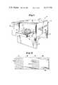
- FIG. 5is a cross-sectional view taken generally along lines 5-5 of FIG. 2;
- FIG. 6is a partial cross-sectional view taken generally along lines 6--6 of FIG. 2.
- FIG. 7is a view similar to FIG. 5 illustrating an alternate embodiment of the present tunnel heater.
- FIG. 8is a view similar to FIG. 6 further illustrating the alternate embodiment of the present invention.
- heater 10is arranged to cook or otherwise heat food products by forced hot air convection, and includes a food product conveying arrangement so that food products to be heated may be automatically moved through the heater for cooking.
- Tunnel heater 10includes a generally box-like heater housing 12 supported upon legs 14. Notably, heater 10 is designed so that one heater can be stacked upon another, which is particularly useful where space is somewhat limited.
- Heater housing 12includes an outer upper wall 16 and an outer lower wall 18. The housing further includes spaced outer side walls 20 and 22, and spaced outer end walls 24 and 26. Each of end walls 24 and 26 defines an opening at the respective ends of a tunnel-like cavity 28 which extends the length of heater 10.
- Cavity 28is adapted to receive food products to be heated, and to this end a conveyor 30 is provided which extends the length of cavity 28 and beyond the ends thereof.
- Conveyor 30includes an upper conveyor run 32 and a lower, return conveyor run 34 so that food products, such as 36, may be placed upon the upper conveyor run 32 and advanced through tunnel cavity 28 of the heater. In this manner, food products are received through one end of cavity 28, moved through the cavity on conveyor 30, and discharged from the conveyor at the other end of cavity 28.
- Conveyor 30is preferably provided with a variable speed control so that heating times of food products conveyed can be selectively varied.
- outer side wall 20 of the heater housing 12may be provided with an elongated observation window 38 so that food products being conveyed through the heater may be readily inspected.
- Window 38may be provided with sliding glass doors or the like to permit ready access to tunnel cavity 28 intermediate the ends thereof.
- tunnel heater 10provides for circulation of heated air within the heater housing 12 so that the heated air is directed against the upper and lower surfaces of food products conveyed through the heater.
- a pair of centrifugal blowers 40is provided for drawing air from within cavity 28, although a single blower or more than two blowers could of course be used.
- Each blower 40is provided with its own electric motor 42, with the blowers 40 arranged so that air drawn from cavity 28 is drawn into heating chamber 44 through a plurality of upper and lower intake holes 46 and 47 defined by a generally vertically disposed intake plate 48.
- heating chamber 44is further defined by upper and lower duct plates 50 which are positioned generally above and below intake plate 48.
- Air drawn into heating chamber 44is heated by a heater comprising a burner 52 which extends into the heating chamber.
- An electric heatercan also be readily employed in the present tunnel heater.
- Burner 52is preferably gas-fired, and is provided with a generally cylindrical flame tube 54 which extends into heating chamber 44 and within which combustion by the burner 52 takes place. Burner 52 operates to selectively heat air drawn through heating chamber 44 in response to thermostatically-regulated automatic controls, designated generally at 56.
- flame tube 54minimizes direct impingement of heat energy from the burner on blowers 40 disposed immediately downstream of the heating chamber 44. Without flame tube 54, blowers 40 would otherwise tend to suck flames from burner 53 into the blower intakes.
- Circulated air heated within heating chamber 44is drawn into centrifugal blowers 40 through respective blower intakes 58 which define the low pressure or suction side of each blower.
- the heated, circulating airis blown radially from the blowers 40 in blower chambers 60 within which each of blowers 40 is respectively disposed.
- blower chambers 60The configuration of the blower chambers 60 is significant for providing aerodynamically efficient air flow as the circulating air is ducted from the blowers back to tunnel cavity 28.
- Each blower chamber 60is defined by a respective end wall 62, and common top and bottom walls 64 and 66.
- the blower chambersare further defined by a common rear wall 68 which is spaced inwardly of outer side wall 22 of heater housing 12.
- suitable thermal insulation 69is provided between outer side wall 22 and rear wall 68.
- a dividing wall 70extends vertically from top wall 64 to bottom wall 66 and distinguishes the two blower chambers from each other.
- a plurality of arcuate plate arrangements 72defines aerodynamically efficient, first and second pairs of generally scroll-shaped air flow passages 73, with each pair of passages in close association with and extending about a respective one of blowers 40.
- the passages 73 of each pairare generally opposed to each other, with each extending approximately halfway about the respective blower 40.
- the passages 73 of each pairare arranged for opposite blower discharge to substantially equally distribute and duct air from the respective blower 40 to upper and lower sides of tunnel cavity 28 for flow against food products in the cavity. This arrangement for ducting circulating air flow within tunnel heater 10 has been found to promote highly efficient operation, which provides for fast and readily-controllable heating of food products conveyed through tunnel cavity 28.
- Air from within the blower chambers 60is circulated therefrom through upper and lower portions of discharge plate 74 to upper and lower air flow passages 77 and 79 (with blower intakes 58 disposed generally centrally of discharge plate 74).
- Discharge plate 74defines a plurality of discharge openings 78, with each discharge opening 78 receiving flow from a respective one of scroll-shaped passages 73.
- This preferred arrangement of discharge plate 74cooperates with the scroll-shaped passages 73 so that generally equal portions of the air circulated by each blower 40 are respectively channeled through either one of the upper or lower air flow passages 77 and 79 through which the air circulates.
- Air flow efficiencyis enhanced by the provision of arcuate guides 80 which are positioned generally adjacent rear wall 68, and are arranged to guide the flow of circulating air through discharge plate 74 transversely of the scroll-shaped passages 73 which extend about blowers 40.
- the duct work of the present tunnel heaterwhich defines upper and lower air flow passages 77 and 79 provides each of these passages with a venturi-like configuration for directing heated air from the blowers 40 back to the tunnel cavity 28 for heating food products.
- Upper and lower air flow passages 77 and 79are respectively defined by upper and lower duct walls 82 and 84, which extend from discharge plate 74 and converge toward the opposite side of the heater housing 12.
- the upper and lower venturi-like air flow passages 77 and 79are further defined by duct plates 50 disposed above and below intake plate 48 of heating chamber 44.
- arcuate guides 80 within blower chambers 60act to guide circulating air from the scroll-shaped passages 73 about blowers 40 into the venturi-like air passages 77 and 79 downstream thereof.
- the present apparatusincludes upper and lower foraminous plates 86 and 88.
- Upper and lower plates 86 and 88are respectively disposed above and below and adjacent to tunnel cavity 28.
- Upper plate 86 and lower plate 88are positioned inwardly of and between upper and lower intake holes 46 and 47 in intake plate 48.
- Intake holes 46communicate with cavity 28 on the same side of the upper plate 86 that is associated with air passage 77.
- intake holes 47communicate with cavity 28 on the same side of the lower plate 88 that is associated with air passage 79.
- Upper and lower plates 86 and 88respectively extend from duct plates 50 to inner wall 90.
- the inner wall 90is spaced from the outer side wall 20 of heater housing 12, with suitable thermal insulation provided therebetween for minimizing heat transfer from the heated circulating air to the heater housing.
- Each plate 86 and 88is slidably supported by channels 94 and 96 which permit the plates to be easily removed for cleaning or servicing of the tunnel heater.
- each plate 86 and 88includes at least one perforated portion 97, which includes a plurality of relatively closely spaced air passage holes 98, and at least one imperforate portion 99 adjacent perforated portion 97.
- each plate 86 and 88includes a plurality of respectively vertically aligned perforated and imperforate portions 97 and 99 extending generally transversely to the path of food products conveyed through tunnel cavity 28.
- the food productsare conveyed through generally adjacent, non-discrete, alternating zones or areas of relatively high and relatively low convective heating. Passage of food products through high and low heating zones in this manner is desirable since moisture in the food products being heated is permitted to migrate toward the surfaces of the products during passage of the products through the zones of relatively low convective heating. More uniform heating of the products thereby results, providing cooked products have improved quality and appeal.
- This method of heating food productsis particularly effective for heating or baking products having crusts or the like, resulting in products having the desired texture and doneness throughout.
- upper and lower plates 86 and 88can be made to provide different rates of heating of the upper and lower surfaces of the products by varying the size, number and distribution of holes in the plates.
- the relative spacing of food products from the plates 86 and 88also affects the rate of product heating.
- productsare conveyed through cavity 23 so that their surfaces are spaced between approximately one to three inches from the plates 86 and 88.
- relative spacing of conveyed products for optimum resultswill, of course, depend upon the configuration of plates 86 and 88, the rate and velocity of air flow against and about the products, and the temperature of the circulating air. These design parameters can be varied while still obtaining the desired efficient and readily controlled heating provided by the present apparatus.
- each plate 86 and 88is fabricated from 18 gauge stainless steel and each hole 98 of perforated portions 97 is approximately 5/16 of an inch in diameter.
- Each perforated portion 97includes six rows of holes 98 with adjacent holes of each row spaced on approximately 5/8 inch centers. Adjacent rows of holes 98 are staggered with respect to each other by approximately 1/8 inch. While various other perforated configurations for foraminous upper and lower plates 86 and 88 can also be used, this particular sizing and spacing of holes 98 has been found to provide the desired high velocity, blanket-like flow of heated air against food products conveyed through tunnel cavity 28.
- the ducting of the heated circulating air through the venturi-like upper and lower air flow passages 77 and 79creates a relative increase in the pressure of the circulated air upstream of upper and lower plates 88 and 86 before the air passes through the plates and is directed against food products for heating.
- the overall arrangement of the aerodynamically efficient duct work of the present tunnel heatergreatly promotes efficient heating of food products.
- the efficient air flow provided by the present arrangementminimizes heat energy losses by passage of air from the open ends of tunnel cavity 28.
- the internal duct work of the tunnel heateris supported within the heater housing 12 so that conductive heat transfer from the heated circulating air to outer portions of the heater housing is minimized.
- supports 100respectively extend between the upper and lower outer walls 16 and 18 of the heater housing 12 and top and bottom walls 64 and 66 about blower chambers 60 within the housing.
- Each support 100includes a plurality of spaced holes 102 so that each support 100 includes a portion of reduced cross-section so that conductive heat transfer therethrough is minimized.
- supports 104are provided extending between end wall 90 and upper and lower outer walls 16 and 18, with supports 104 each defining a plurality of holes 106 for providing each support with a portion of reduced cross-section for minimizing conductive heat transfer therethrough.
- supports such as 100 and 104together with suitable thermal insulation, permits the outer surfaces of heater housing 12 to remain relatively cool even though air circulated within the heater may be heated to temperatures on the order of several hundred degrees Fahrenheit.
- each of two blowers 40 provided in the tunnel heaterhas a rated air flow capacity of approximately 1250 cubic feet per minute (CFM), with working air flow through each blower being approximately 750 CFM.
- Upper and lower foraminous plates 86 and 88each include two plate sections fitted side-by-side so that generally continuous upper and lower plates 86 and 88 are provided extending substantially the length of tunnel cavity 28.
- Each plate 86 and 88includes six spaced perforated portions 97 having holes 98 spaced as described above.
- Circulating airis heated by burner 52 having a maximum rated output of approximately 100,000 BTU/hour, with the burner typically operating at a rate of 30,000-50,000 BTU/hour.
- Circulating air flow velocity within venturi-like air flow passages 77 and 79reaches approximately 3800-4000 feet/minute through the areas of reduced cross-section, with air velocity decreasing to approximately 1400-1600 feet/minute upstream of foraminous plates 86 and 88.
- the velocity of air flow against food products in cavity 28is on the order of approximately 1800-2000 feet/minute.
- This particular embodiment of the present tunnel heaterhas proven to provide highly acceptable results for commercial use. However, a wide variety of operating conditions can be readily provided in a heater apparatus made in accordance with the teachings herein.
- an alternate embodiment for the circulating air duct work of the present heateris disclosed.
- This embodimentincludes a different arrangement for the chambers within which blowers 40 are positioned which acts to enhance aerodynamically efficient air flow in a manner similar to the arrangement of blower chambers 60.
- Each blower chamber 160is defined by a respective end wall 162, and common top and bottom walls 164 and 166.
- the blower chambersare further defined by a common rear wall 168 (spaced outwardly of outer side wall 22 of heater housing 12.)
- a dividing wall 170extends angularly from top wall 164 to bottom wall 166 and distinguishes the blower chambers 160 from each other.
- dividing wall 170together with a plurality of arcuate plate arrangements 172, defines aerodynamically efficient, generally scroll-shaped air flow passages 173 which are closely associated with and respectively extend about the blowers 40.
- this arrangement of chambers 160 for ducting circulating air flowhas been found to promote highly efficient operation.
- Air from within the blower chambers 160is circulated therefrom through upper and lower portions of discharge plate 174 (positioned within heater 10 like discharge plate 74) to the upper and lower air flow passages 77 and 79.
- Discharge plate 174defines discharge openings 178 and 179 through which air circulated by blowers 40 flows.
- Discharge plate 174acts in cooperation with blower chambers 160 to baffle air flow from the blowers 40 for distribution to upper and lower air flow passages 77 and 79. If desired, the configuration of discharge plate 174 can be provided so that air flow from each blower 42 is evenly distributed between passages 77 and 79.
- a predominent portion of the air flow from one of the blowerscan be directed to one of passages 77 and 79, with a predominant air flow from the other blower directed to the other of the passages 77 and 79.
- This latter flow distributionis achieved by sizing and positioning discharge openings 178 and 179 generally as illustrated.
- Other baffling arrangementscan also be used.
- Air flow efficiencyis enhanced by the provision of arcuate air flow guides 130 which are positioned generally adjacent rear wall 168, and are arranged to guide the flow of circulating air through discharge plate 174 transversely of the scroll-shaped passages 173 which respectively extend about each blower 40.
- a tunnel heater apparatuswhich greatly facilitates efficient heating and preparation of food products.
- the present arrangementnot only heats food products in a relatively rapid fashion by the use of forced air convection for cooking, but is also energy efficient, with aerodynamically correct air flow passages promoting smooth and efficient circulation of heated air for heating food products.
Landscapes
- Life Sciences & Earth Sciences (AREA)
- Engineering & Computer Science (AREA)
- Food Science & Technology (AREA)
- Baking, Grill, Roasting (AREA)
- Commercial Cooking Devices (AREA)
Abstract
Description
Claims (11)
Priority Applications (6)
| Application Number | Priority Date | Filing Date | Title |
|---|---|---|---|
| US06/379,738US4471750A (en) | 1982-05-19 | 1982-05-19 | Tunnel heater |
| IE1079/83AIE54190B1 (en) | 1982-05-19 | 1983-05-10 | Apparatus and method for heating food products |
| DE8383302737TDE3367456D1 (en) | 1982-05-19 | 1983-05-16 | Apparatus and method for heating food products |
| EP83302737AEP0094816B1 (en) | 1982-05-19 | 1983-05-16 | Apparatus and method for heating food products |
| CA000428350ACA1193898A (en) | 1982-05-19 | 1983-05-17 | Tunnel heater |
| US06/606,138US4576090A (en) | 1982-05-19 | 1984-05-02 | Tunnel heater |
Applications Claiming Priority (1)
| Application Number | Priority Date | Filing Date | Title |
|---|---|---|---|
| US06/379,738US4471750A (en) | 1982-05-19 | 1982-05-19 | Tunnel heater |
Related Child Applications (1)
| Application Number | Title | Priority Date | Filing Date |
|---|---|---|---|
| US06/606,138Continuation-In-PartUS4576090A (en) | 1982-05-19 | 1984-05-02 | Tunnel heater |
Publications (1)
| Publication Number | Publication Date |
|---|---|
| US4471750Atrue US4471750A (en) | 1984-09-18 |
Family
ID=23498480
Family Applications (1)
| Application Number | Title | Priority Date | Filing Date |
|---|---|---|---|
| US06/379,738Expired - LifetimeUS4471750A (en) | 1982-05-19 | 1982-05-19 | Tunnel heater |
Country Status (5)
| Country | Link |
|---|---|
| US (1) | US4471750A (en) |
| EP (1) | EP0094816B1 (en) |
| CA (1) | CA1193898A (en) |
| DE (1) | DE3367456D1 (en) |
| IE (1) | IE54190B1 (en) |
Cited By (29)
| Publication number | Priority date | Publication date | Assignee | Title |
|---|---|---|---|---|
| US4576090A (en)* | 1982-05-19 | 1986-03-18 | Mastermatic, Inc. | Tunnel heater |
| US4616562A (en)* | 1985-06-21 | 1986-10-14 | Kuechler Irvin R | Ventilation system for pizza ovens |
| US4753215A (en)* | 1987-01-14 | 1988-06-28 | Lincoln Foodservice Products, Inc. | Burner for low profile inpingement oven |
| US4873107A (en)* | 1986-12-24 | 1989-10-10 | Archer Air Industries, Inc. | Air impingement tunnel oven apparatus |
| US4919477A (en)* | 1988-10-17 | 1990-04-24 | Pizza Hut, Inc. | Compact pizza preparation and delivery vehicle |
| US4924763A (en)* | 1988-10-17 | 1990-05-15 | Pizza Hut | Compact pizza oven |
| US4951645A (en)* | 1988-12-02 | 1990-08-28 | Welbilt Corporation | Stacked duel module commercial hot air impingement cooking oven |
| US4972824A (en)* | 1988-12-02 | 1990-11-27 | Welbilt Corporation | Commercial hot air impingement cooking apparatus |
| US5239917A (en)* | 1991-06-06 | 1993-08-31 | Genie Tech, Inc. | Oven |
| US5421316A (en)* | 1994-01-31 | 1995-06-06 | G. S. Blodgett Corporation | Conveyor oven with improved air flow |
| US5845631A (en)* | 1997-08-21 | 1998-12-08 | Kerry Ingredients, Inc. | Heat exchanger for convection baking ovens |
| WO1999004202A3 (en)* | 1997-07-18 | 1999-04-08 | Gottfried Riesselmann | Apparatus for cooking dishes by heating |
| WO2002003804A1 (en)* | 2000-07-10 | 2002-01-17 | Lincoln Foodservice Products, Inc. | Conveyor oven |
| US20060157479A1 (en)* | 2004-12-14 | 2006-07-20 | Enodis Corporation | Impingement/convection/microwave oven and method |
| US20070295322A1 (en)* | 2004-12-03 | 2007-12-27 | Dobie Michael J | High Speed Convection Oven |
| US7624728B1 (en)* | 2004-12-22 | 2009-12-01 | David C Forbes | Impingement tunnel oven with reduced energy consumption and reduced maintenance |
| US20100012644A1 (en)* | 2008-07-18 | 2010-01-21 | Electrolux Home Products, Inc. | Dual fan convection performance divider |
| US7820216B1 (en)* | 2007-10-23 | 2010-10-26 | Alkar-Rapidpak-Mp Equipment, Inc. | Apparatus and methods for pasteurizing food product |
| US8637792B2 (en) | 2011-05-18 | 2014-01-28 | Prince Castle, LLC | Conveyor oven with adjustable air vents |
| US20140199446A1 (en)* | 2013-01-11 | 2014-07-17 | Star Manufacturing International, Inc. | Split-Belt Conveyor Toaster |
| US20150072603A1 (en)* | 2012-03-30 | 2015-03-12 | Oxford Optronix Limited | Controlled Atmosphere Workstation |
| US9044024B2 (en) | 2011-01-14 | 2015-06-02 | Cleveland Range, Llc | Oven door |
| US9677774B2 (en) | 2015-06-08 | 2017-06-13 | Alto-Shaam, Inc. | Multi-zone oven with variable cavity sizes |
| US9879865B2 (en) | 2015-06-08 | 2018-01-30 | Alto-Shaam, Inc. | Cooking oven |
| US10088172B2 (en) | 2016-07-29 | 2018-10-02 | Alto-Shaam, Inc. | Oven using structured air |
| US10337745B2 (en) | 2015-06-08 | 2019-07-02 | Alto-Shaam, Inc. | Convection oven |
| US10890336B2 (en) | 2015-06-08 | 2021-01-12 | Alto-Shaam, Inc. | Thermal management system for multizone oven |
| US11266152B2 (en)* | 2016-03-09 | 2022-03-08 | Dmp Enterprises Pty Ltd | Conveyer-type oven |
| US20220395139A1 (en)* | 2021-06-15 | 2022-12-15 | Jiangmen City Xinhui Henglong Innovative Housewares Co., Ltd. | Toaster |
Families Citing this family (6)
| Publication number | Priority date | Publication date | Assignee | Title |
|---|---|---|---|---|
| DE3306972C2 (en)* | 1983-02-28 | 1987-01-22 | Buderus Ag, 6330 Wetzlar | Device for heat treatment of food and dishes |
| EP0276225A4 (en)* | 1986-12-24 | 1989-04-12 | Archer Aire Ind Inc | Air slot cooking grill. |
| US4949629A (en)* | 1987-10-13 | 1990-08-21 | Heat And Control, Inc. | Cooking a food product in a process vapor at progressively varying rates |
| USD306064S (en) | 1988-03-11 | 1990-02-13 | Zephyr Convection Cooking Systems Co. | Convection blower or similar article for use in an electric oven |
| CA2191786A1 (en)* | 1996-11-29 | 1998-05-29 | Georges Moshonas | Impingement food apparatus |
| IT201700117996A1 (en)* | 2017-10-18 | 2019-04-18 | Prismafood S R L | COOKING SYSTEM FOR FOOD AND ITS METHOD |
Citations (35)
| Publication number | Priority date | Publication date | Assignee | Title |
|---|---|---|---|---|
| US1617609A (en)* | 1922-03-16 | 1927-02-15 | Gas Res Co | Apparatus for effecting heat transfer |
| US1717115A (en)* | 1928-05-19 | 1929-06-11 | Mccann Harry Paul | Ventilating system for ovens |
| US1847915A (en)* | 1930-03-08 | 1932-03-01 | Thermox Inc | Apparatus for drying paper and the like |
| US1860887A (en)* | 1930-08-19 | 1932-05-31 | Charles E Buysse | Furnace |
| US2330938A (en)* | 1941-11-14 | 1943-10-05 | Torrington Mfg Co | Multiple outlet blower assembly |
| US2491687A (en)* | 1945-06-26 | 1949-12-20 | Nutt John Henry | Apparatus for baking dough products |
| US2504320A (en)* | 1945-02-26 | 1950-04-18 | Lindberg Eng Co | Method of and apparatus for forced convection heating |
| US2674811A (en)* | 1950-11-17 | 1954-04-13 | Us Rubber Co | Drier for porous materials |
| US2908234A (en)* | 1954-06-12 | 1959-10-13 | T & T Vicars Ltd | Bakers' and the like ovens |
| US3015893A (en)* | 1960-03-14 | 1962-01-09 | Mccreary John | Fluid flow control device for tenter machines utilizing super-heated steam |
| US3065553A (en)* | 1962-11-27 | R olin | ||
| US3074179A (en)* | 1960-08-26 | 1963-01-22 | Faustel Inc | Web dryer |
| US3104187A (en)* | 1958-04-15 | 1963-09-17 | Owens Illinois Glass Co | Method for cleaning corrugated partition strips |
| US3129072A (en)* | 1958-12-29 | 1964-04-14 | Midland Ross Corp | Heat transfer apparatus for continuously moving strip |
| US3173384A (en)* | 1961-06-07 | 1965-03-16 | Baker Perkins Inc | Baking oven |
| US3266559A (en)* | 1963-02-15 | 1966-08-16 | American Mach & Foundry | Method of drying foamed materials, e. g. foods |
| US3374106A (en)* | 1964-05-14 | 1968-03-19 | Proctor & Schwartz Inc | Material drying method and apparatus |
| US3514576A (en)* | 1968-06-24 | 1970-05-26 | Hirst Microwave Heating Ltd | Combined microwave and hot air oven |
| US3561885A (en)* | 1969-08-11 | 1971-02-09 | Pyronics Inc | Blower housing |
| US3590803A (en)* | 1968-07-20 | 1971-07-06 | Burger Eisenwerke Ag | Food-treatment apparatus with gas-circulating means |
| US3605717A (en)* | 1969-11-10 | 1971-09-20 | Crown X Inc | Convection oven |
| US3626922A (en)* | 1969-01-31 | 1971-12-14 | Gas Council | Forced convection oven |
| US3692968A (en)* | 1970-04-06 | 1972-09-19 | Sanyo Electric Co | Electronic oven |
| US3747513A (en)* | 1972-03-03 | 1973-07-24 | K C Seelback Co Inc | Apparatus for processing foodstuffs |
| US3821454A (en)* | 1971-12-15 | 1974-06-28 | Leon Lobel | Method of ageing meat |
| US3884213A (en)* | 1973-03-30 | 1975-05-20 | Donald P Smith | Cooking apparatus |
| US3908533A (en)* | 1973-04-04 | 1975-09-30 | Electrolux Ab | Apparatus for continuously cooking food in sequential oven section of an elongated oven |
| US3926106A (en)* | 1972-06-15 | 1975-12-16 | Burger Eisenwerke Ag | Food-treatment apparatus with circulated hot combustion gas |
| US4109636A (en)* | 1976-12-22 | 1978-08-29 | British Gas Corporation | Forced convection ovens |
| DE2709068A1 (en)* | 1977-03-02 | 1978-09-07 | Debag Deutsche Backofenbau | Narrow width baking oven - with heating unit and blowers mounted on top of baking chamber and side channels |
| US4154861A (en)* | 1976-05-19 | 1979-05-15 | Smith Donald P | Heat treatment of food products |
| US4235591A (en)* | 1977-05-24 | 1980-11-25 | Gautschi Electro-Fours SA. | Continuous flow oven |
| US4320587A (en)* | 1979-03-03 | 1982-03-23 | Hilmar Vits | Dryer for a continuously traveling web |
| US4338911A (en)* | 1976-05-19 | 1982-07-13 | Smith Donald P | Cooking apparatus |
| US4357522A (en)* | 1979-12-18 | 1982-11-02 | Bosch-Siemens Hausgerate Gmbh | Baking oven |
Family Cites Families (4)
| Publication number | Priority date | Publication date | Assignee | Title |
|---|---|---|---|---|
| SE363229B (en)* | 1972-03-15 | 1974-01-14 | Electrolux Ab | |
| DE7238931U (en)* | 1972-10-24 | 1973-03-29 | Licentia Gmbh | COOKING STOVE WITH CIRCULATION OF A HOT AIR FLOW THROUGH A FAN IN A WARM ROOM THAT CAN BE LOCKED FROM THE OUTSIDE |
| DE2400845A1 (en)* | 1974-01-09 | 1975-07-17 | Burger Eisenwerke Ag | DEVICE FOR HEAT TREATMENT OF FOOD AND FOOD |
| SE409164B (en)* | 1978-06-19 | 1979-08-06 | Tipe Revent Ab | BAKUGN |
- 1982
- 1982-05-19USUS06/379,738patent/US4471750A/ennot_activeExpired - Lifetime
- 1983
- 1983-05-10IEIE1079/83Apatent/IE54190B1/ennot_activeIP Right Cessation
- 1983-05-16DEDE8383302737Tpatent/DE3367456D1/ennot_activeExpired
- 1983-05-16EPEP83302737Apatent/EP0094816B1/ennot_activeExpired
- 1983-05-17CACA000428350Apatent/CA1193898A/ennot_activeExpired
Patent Citations (35)
| Publication number | Priority date | Publication date | Assignee | Title |
|---|---|---|---|---|
| US3065553A (en)* | 1962-11-27 | R olin | ||
| US1617609A (en)* | 1922-03-16 | 1927-02-15 | Gas Res Co | Apparatus for effecting heat transfer |
| US1717115A (en)* | 1928-05-19 | 1929-06-11 | Mccann Harry Paul | Ventilating system for ovens |
| US1847915A (en)* | 1930-03-08 | 1932-03-01 | Thermox Inc | Apparatus for drying paper and the like |
| US1860887A (en)* | 1930-08-19 | 1932-05-31 | Charles E Buysse | Furnace |
| US2330938A (en)* | 1941-11-14 | 1943-10-05 | Torrington Mfg Co | Multiple outlet blower assembly |
| US2504320A (en)* | 1945-02-26 | 1950-04-18 | Lindberg Eng Co | Method of and apparatus for forced convection heating |
| US2491687A (en)* | 1945-06-26 | 1949-12-20 | Nutt John Henry | Apparatus for baking dough products |
| US2674811A (en)* | 1950-11-17 | 1954-04-13 | Us Rubber Co | Drier for porous materials |
| US2908234A (en)* | 1954-06-12 | 1959-10-13 | T & T Vicars Ltd | Bakers' and the like ovens |
| US3104187A (en)* | 1958-04-15 | 1963-09-17 | Owens Illinois Glass Co | Method for cleaning corrugated partition strips |
| US3129072A (en)* | 1958-12-29 | 1964-04-14 | Midland Ross Corp | Heat transfer apparatus for continuously moving strip |
| US3015893A (en)* | 1960-03-14 | 1962-01-09 | Mccreary John | Fluid flow control device for tenter machines utilizing super-heated steam |
| US3074179A (en)* | 1960-08-26 | 1963-01-22 | Faustel Inc | Web dryer |
| US3173384A (en)* | 1961-06-07 | 1965-03-16 | Baker Perkins Inc | Baking oven |
| US3266559A (en)* | 1963-02-15 | 1966-08-16 | American Mach & Foundry | Method of drying foamed materials, e. g. foods |
| US3374106A (en)* | 1964-05-14 | 1968-03-19 | Proctor & Schwartz Inc | Material drying method and apparatus |
| US3514576A (en)* | 1968-06-24 | 1970-05-26 | Hirst Microwave Heating Ltd | Combined microwave and hot air oven |
| US3590803A (en)* | 1968-07-20 | 1971-07-06 | Burger Eisenwerke Ag | Food-treatment apparatus with gas-circulating means |
| US3626922A (en)* | 1969-01-31 | 1971-12-14 | Gas Council | Forced convection oven |
| US3561885A (en)* | 1969-08-11 | 1971-02-09 | Pyronics Inc | Blower housing |
| US3605717A (en)* | 1969-11-10 | 1971-09-20 | Crown X Inc | Convection oven |
| US3692968A (en)* | 1970-04-06 | 1972-09-19 | Sanyo Electric Co | Electronic oven |
| US3821454A (en)* | 1971-12-15 | 1974-06-28 | Leon Lobel | Method of ageing meat |
| US3747513A (en)* | 1972-03-03 | 1973-07-24 | K C Seelback Co Inc | Apparatus for processing foodstuffs |
| US3926106A (en)* | 1972-06-15 | 1975-12-16 | Burger Eisenwerke Ag | Food-treatment apparatus with circulated hot combustion gas |
| US3884213A (en)* | 1973-03-30 | 1975-05-20 | Donald P Smith | Cooking apparatus |
| US3908533A (en)* | 1973-04-04 | 1975-09-30 | Electrolux Ab | Apparatus for continuously cooking food in sequential oven section of an elongated oven |
| US4154861A (en)* | 1976-05-19 | 1979-05-15 | Smith Donald P | Heat treatment of food products |
| US4338911A (en)* | 1976-05-19 | 1982-07-13 | Smith Donald P | Cooking apparatus |
| US4109636A (en)* | 1976-12-22 | 1978-08-29 | British Gas Corporation | Forced convection ovens |
| DE2709068A1 (en)* | 1977-03-02 | 1978-09-07 | Debag Deutsche Backofenbau | Narrow width baking oven - with heating unit and blowers mounted on top of baking chamber and side channels |
| US4235591A (en)* | 1977-05-24 | 1980-11-25 | Gautschi Electro-Fours SA. | Continuous flow oven |
| US4320587A (en)* | 1979-03-03 | 1982-03-23 | Hilmar Vits | Dryer for a continuously traveling web |
| US4357522A (en)* | 1979-12-18 | 1982-11-02 | Bosch-Siemens Hausgerate Gmbh | Baking oven |
Cited By (45)
| Publication number | Priority date | Publication date | Assignee | Title |
|---|---|---|---|---|
| US4576090A (en)* | 1982-05-19 | 1986-03-18 | Mastermatic, Inc. | Tunnel heater |
| US4616562A (en)* | 1985-06-21 | 1986-10-14 | Kuechler Irvin R | Ventilation system for pizza ovens |
| US4873107A (en)* | 1986-12-24 | 1989-10-10 | Archer Air Industries, Inc. | Air impingement tunnel oven apparatus |
| US4753215A (en)* | 1987-01-14 | 1988-06-28 | Lincoln Foodservice Products, Inc. | Burner for low profile inpingement oven |
| US4919477A (en)* | 1988-10-17 | 1990-04-24 | Pizza Hut, Inc. | Compact pizza preparation and delivery vehicle |
| US4924763A (en)* | 1988-10-17 | 1990-05-15 | Pizza Hut | Compact pizza oven |
| US4951645A (en)* | 1988-12-02 | 1990-08-28 | Welbilt Corporation | Stacked duel module commercial hot air impingement cooking oven |
| US4972824A (en)* | 1988-12-02 | 1990-11-27 | Welbilt Corporation | Commercial hot air impingement cooking apparatus |
| US5345923A (en)* | 1988-12-02 | 1994-09-13 | Welbilt Corporation | Commercial hot air impingement cooking apparatus |
| US5239917A (en)* | 1991-06-06 | 1993-08-31 | Genie Tech, Inc. | Oven |
| US5421316A (en)* | 1994-01-31 | 1995-06-06 | G. S. Blodgett Corporation | Conveyor oven with improved air flow |
| EP0664956A3 (en)* | 1994-01-31 | 1998-01-28 | G.S. Blodgett Corporation | Conveyor oven with improved air flow |
| US6450085B1 (en) | 1997-07-18 | 2002-09-17 | Gottfried Riesselmann | Apparatus for cooking dishes by heating |
| WO1999004202A3 (en)* | 1997-07-18 | 1999-04-08 | Gottfried Riesselmann | Apparatus for cooking dishes by heating |
| US5845631A (en)* | 1997-08-21 | 1998-12-08 | Kerry Ingredients, Inc. | Heat exchanger for convection baking ovens |
| WO2002003804A1 (en)* | 2000-07-10 | 2002-01-17 | Lincoln Foodservice Products, Inc. | Conveyor oven |
| US6526961B1 (en)* | 2000-07-10 | 2003-03-04 | Lincoln Foodservice Products, Inc | Conveyor oven |
| JP2004502438A (en)* | 2000-07-10 | 2004-01-29 | リンカーン フードサービス プロダクツ, インコーポレイテッド | Conveyor oven |
| AU2001273588B2 (en)* | 2000-07-10 | 2005-03-03 | Lincoln Foodservice Products, Inc. | Conveyor oven |
| US20070295322A1 (en)* | 2004-12-03 | 2007-12-27 | Dobie Michael J | High Speed Convection Oven |
| US8042533B2 (en)* | 2004-12-03 | 2011-10-25 | Turbochef Technologies, Inc. | High speed convection oven |
| US20060157479A1 (en)* | 2004-12-14 | 2006-07-20 | Enodis Corporation | Impingement/convection/microwave oven and method |
| US20070278218A1 (en)* | 2004-12-14 | 2007-12-06 | Jan Claesson | Impingement/convection/microwave oven and method |
| US8093538B2 (en) | 2004-12-14 | 2012-01-10 | Enodis Corporation | Impingement/convection/microwave oven and method |
| US8071922B2 (en) | 2004-12-14 | 2011-12-06 | Enodis Corporation | Impingement/convection/microwave oven and method |
| US7834299B2 (en) | 2004-12-14 | 2010-11-16 | Enodis Corporation | Impingement/convection/microwave oven and method |
| US7838807B2 (en) | 2004-12-14 | 2010-11-23 | Enodis Corporation | Impingement/convection/microwave oven and method |
| US7624728B1 (en)* | 2004-12-22 | 2009-12-01 | David C Forbes | Impingement tunnel oven with reduced energy consumption and reduced maintenance |
| US7820216B1 (en)* | 2007-10-23 | 2010-10-26 | Alkar-Rapidpak-Mp Equipment, Inc. | Apparatus and methods for pasteurizing food product |
| US20100012644A1 (en)* | 2008-07-18 | 2010-01-21 | Electrolux Home Products, Inc. | Dual fan convection performance divider |
| US8350192B2 (en)* | 2008-07-18 | 2013-01-08 | Electrolux Home Products, Inc. | Dual fan convection performance divider |
| US9044024B2 (en) | 2011-01-14 | 2015-06-02 | Cleveland Range, Llc | Oven door |
| US8637792B2 (en) | 2011-05-18 | 2014-01-28 | Prince Castle, LLC | Conveyor oven with adjustable air vents |
| US20150072603A1 (en)* | 2012-03-30 | 2015-03-12 | Oxford Optronix Limited | Controlled Atmosphere Workstation |
| US20140199446A1 (en)* | 2013-01-11 | 2014-07-17 | Star Manufacturing International, Inc. | Split-Belt Conveyor Toaster |
| US9879865B2 (en) | 2015-06-08 | 2018-01-30 | Alto-Shaam, Inc. | Cooking oven |
| US9677774B2 (en) | 2015-06-08 | 2017-06-13 | Alto-Shaam, Inc. | Multi-zone oven with variable cavity sizes |
| US10088173B2 (en) | 2015-06-08 | 2018-10-02 | Alto-Shaam, Inc. | Low-profile multi-zone oven |
| US10337745B2 (en) | 2015-06-08 | 2019-07-02 | Alto-Shaam, Inc. | Convection oven |
| US10890336B2 (en) | 2015-06-08 | 2021-01-12 | Alto-Shaam, Inc. | Thermal management system for multizone oven |
| US11754294B2 (en) | 2015-06-08 | 2023-09-12 | Alto-Shaam, Inc. | Thermal management system for multizone oven |
| US11266152B2 (en)* | 2016-03-09 | 2022-03-08 | Dmp Enterprises Pty Ltd | Conveyer-type oven |
| US10088172B2 (en) | 2016-07-29 | 2018-10-02 | Alto-Shaam, Inc. | Oven using structured air |
| US20220395139A1 (en)* | 2021-06-15 | 2022-12-15 | Jiangmen City Xinhui Henglong Innovative Housewares Co., Ltd. | Toaster |
| US11771263B2 (en)* | 2021-06-15 | 2023-10-03 | Jiangmen City Xinhui Henglong Innovative Housewares Co., Ltd. | Toaster |
Also Published As
| Publication number | Publication date |
|---|---|
| EP0094816B1 (en) | 1986-11-05 |
| DE3367456D1 (en) | 1986-12-11 |
| EP0094816A3 (en) | 1984-04-11 |
| CA1193898A (en) | 1985-09-24 |
| EP0094816A2 (en) | 1983-11-23 |
| IE54190B1 (en) | 1989-07-05 |
| IE831079L (en) | 1983-11-19 |
Similar Documents
| Publication | Publication Date | Title |
|---|---|---|
| US4471750A (en) | Tunnel heater | |
| US4576090A (en) | Tunnel heater | |
| CA1110686A (en) | Circulating air oven for holding and cooking food | |
| US6943321B2 (en) | Convection oven with forced airflow circulation zones | |
| US5239917A (en) | Oven | |
| EP1797758B1 (en) | Continuous cooking oven system | |
| CA2041872C (en) | Air delivery system and oven control circuitry cooling system for a low profile impingement oven | |
| CN101589283B (en) | Impingement Air Ovens with High Quality Flow Orifices | |
| US5172682A (en) | Commercial hot air impingement cooking apparatus | |
| US3973551A (en) | Powered circulation oven | |
| US3221729A (en) | Oven supplied with hot air through foraminous duct-shelves | |
| IL44255A (en) | Cooking oven with forced air circulation | |
| JPH0738775B2 (en) | Cooking food products in process steam at progressively variable rates | |
| US3074360A (en) | Oven | |
| CA2152569A1 (en) | Baking oven, particularly for bread or confectionery | |
| US7205507B2 (en) | Food cooking and heating apparatus | |
| US4465701A (en) | Method of convection cooking of food | |
| WO1989000393A1 (en) | Method and apparatus for pulse heating and cooking food products | |
| JPS6115734Y2 (en) | ||
| KR102181713B1 (en) | Indirect heating type barbecue apparatus | |
| SU1163819A1 (en) | Bakery electric oven | |
| JPS5940919Y2 (en) | Combustion generated gas vertical circulation type oven | |
| US20070246033A1 (en) | System to Convey Air for Convection or Static Ovens Through Cylinders and/or Interstice and System of Vertical Opposed Ventilation | |
| JPH09126458A (en) | Convection oven | |
| JP2928230B1 (en) | Smokeless cooker |
Legal Events
| Date | Code | Title | Description |
|---|---|---|---|
| AS | Assignment | Owner name:Q-INDUSTRY FOOD EQUIPMENT COMPANY, A CORP. OF ILL. Free format text:ASSIGNMENT OF ASSIGNORS INTEREST.;ASSIGNOR:BURTEA, CONSTANTIN R.;REEL/FRAME:004054/0972 Effective date:19820518 Owner name:Q-INDUSTRY FOOD EQUIPMENT COMPANY, A CORP. OF IL, Free format text:ASSIGNMENT OF ASSIGNORS INTEREST;ASSIGNOR:BURTEA, CONSTANTIN R.;REEL/FRAME:004054/0972 Effective date:19820518 | |
| AS | Assignment | Owner name:MASTERMATIC,INC.SUBSIDIARY OF THE THE G.S.BLODGETT Free format text:CONDITIONAL ASSIGNMENT;ASSIGNOR:Q INDUSTRIES FOOD EQUIPMENT COMPANY;REEL/FRAME:004056/0558 Effective date:19821021 | |
| STCF | Information on status: patent grant | Free format text:PATENTED CASE | |
| FPAY | Fee payment | Year of fee payment:4 | |
| FEPP | Fee payment procedure | Free format text:PAYOR NUMBER ASSIGNED (ORIGINAL EVENT CODE: ASPN); ENTITY STATUS OF PATENT OWNER: LARGE ENTITY Free format text:PAT HLDR NO LONGER CLAIMS SMALL ENT STAT AS SMALL BUSINESS (ORIGINAL EVENT CODE: LSM2); ENTITY STATUS OF PATENT OWNER: LARGE ENTITY | |
| FPAY | Fee payment | Year of fee payment:8 | |
| AS | Assignment | Owner name:TORONTO-DOMINION (TEXAS), INC., TEXAS Free format text:SECURITY INTEREST;ASSIGNOR:G.S. BLODGETT CORPORATION SUCCESSOR BY MERGER TO B.M.G. NEWCO, INC.;REEL/FRAME:007132/0370 Effective date:19940715 | |
| AS | Assignment | Owner name:FLEET BANK - NH, AS AGENT, NEW HAMPSHIRE Free format text:ASSIGNMENT OF SECURITY INTEREST;ASSIGNOR:TORONTO DOMINION (TEXAS), INC.;REEL/FRAME:007677/0730 Effective date:19950728 | |
| FPAY | Fee payment | Year of fee payment:12 | |
| AS | Assignment | Owner name:G.S. BLODGETT CORPORATION, VERMONT Free format text:RELEASE OF SECURITY AGREEMENT;ASSIGNOR:FLEET BANK - NH;REEL/FRAME:008829/0076 Effective date:19961001 |