US4471646A - Blood pressure cuff calibration system - Google Patents
Blood pressure cuff calibration systemDownload PDFInfo
- Publication number
- US4471646A US4471646AUS06/414,904US41490482AUS4471646AUS 4471646 AUS4471646 AUS 4471646AUS 41490482 AUS41490482 AUS 41490482AUS 4471646 AUS4471646 AUS 4471646A
- Authority
- US
- United States
- Prior art keywords
- pressure
- cuff
- support
- measuring
- measuring apparatus
- Prior art date
- Legal status (The legal status is an assumption and is not a legal conclusion. Google has not performed a legal analysis and makes no representation as to the accuracy of the status listed.)
- Expired - Fee Related
Links
Images
Classifications
- A—HUMAN NECESSITIES
- A61—MEDICAL OR VETERINARY SCIENCE; HYGIENE
- A61B—DIAGNOSIS; SURGERY; IDENTIFICATION
- A61B5/00—Measuring for diagnostic purposes; Identification of persons
- A61B5/02—Detecting, measuring or recording for evaluating the cardiovascular system, e.g. pulse, heart rate, blood pressure or blood flow
- A61B5/021—Measuring pressure in heart or blood vessels
- A61B5/02141—Details of apparatus construction, e.g. pump units or housings therefor, cuff pressurising systems, arrangements of fluid conduits or circuits
- A—HUMAN NECESSITIES
- A61—MEDICAL OR VETERINARY SCIENCE; HYGIENE
- A61B—DIAGNOSIS; SURGERY; IDENTIFICATION
- A61B5/00—Measuring for diagnostic purposes; Identification of persons
- A61B5/02—Detecting, measuring or recording for evaluating the cardiovascular system, e.g. pulse, heart rate, blood pressure or blood flow
- A61B5/021—Measuring pressure in heart or blood vessels
- A61B5/0215—Measuring pressure in heart or blood vessels by means inserted into the body
- A61B5/02156—Calibration means
- A—HUMAN NECESSITIES
- A61—MEDICAL OR VETERINARY SCIENCE; HYGIENE
- A61B—DIAGNOSIS; SURGERY; IDENTIFICATION
- A61B5/00—Measuring for diagnostic purposes; Identification of persons
- A61B5/02—Detecting, measuring or recording for evaluating the cardiovascular system, e.g. pulse, heart rate, blood pressure or blood flow
- A61B5/021—Measuring pressure in heart or blood vessels
- A61B5/022—Measuring pressure in heart or blood vessels by applying pressure to close blood vessels, e.g. against the skin; Ophthalmodynamometers
- A61B5/02233—Occluders specially adapted therefor
- G—PHYSICS
- G01—MEASURING; TESTING
- G01L—MEASURING FORCE, STRESS, TORQUE, WORK, MECHANICAL POWER, MECHANICAL EFFICIENCY, OR FLUID PRESSURE
- G01L27/00—Testing or calibrating of apparatus for measuring fluid pressure
- G01L27/002—Calibrating, i.e. establishing true relation between transducer output value and value to be measured, zeroing, linearising or span error determination
- G01L27/005—Apparatus for calibrating pressure sensors
- G—PHYSICS
- G01—MEASURING; TESTING
- G01L—MEASURING FORCE, STRESS, TORQUE, WORK, MECHANICAL POWER, MECHANICAL EFFICIENCY, OR FLUID PRESSURE
- G01L27/00—Testing or calibrating of apparatus for measuring fluid pressure
- G01L27/007—Malfunction diagnosis, i.e. diagnosing a sensor defect
Definitions
- This inventionrelates to blood pressure cuffs, and more particularly to a system for measuring the pressure-transmitting characteristics of cuffs employed for the measurement of arterial blood pressure.
- an object of the inventionis to overcome the deficiencies and disadvantages of the prior art, such as indicated above.
- Another objectis to provide for measuring the pressure-transmitting characteristics of a blood pressure cuff.
- a further object of the inventionis to provide an improved apparatus for measuring the pressure transmitted across the walls of a blood pressure cuff for the purpose of improving the accuracy of measurement of arterial blood pressure.
- a still further object of the inventionis to provide an improved system for determining how much pressure from a cuff is being delivered to the surface of an appendage such as a human arm or an animal limb, so as to obtain a calibration curve showing the pressure-transmitting characteristics of the cuff, which can be used to provide a more accurate determination of blood pressure than has heretofore been obtainable.
- a still further object of the inventionis to provide an apparatus for enabling a comparison to be made between a pressure transmission curve made with a particular cuff and a pressure transmission curve made with the apparatus without the cuff, such comparison indicating the ability of the cuff to transmit its internal pressure across its walls, and thus to determine its ability to deliver its pressure to the surface of an appendage such as an arm.
- a still further object of the inventionis to provide a cuff testing apparatus which allows one to separate the equipment concerns of blood pressure measurement from the physiological concerns, and allows a manufacturer or a standards laboratory to check the cuff properties at the time of manufacture and during its life.
- a still further object of the inventionis to provide a cuff testing apparatus which is easily adaptable for different sizes and widths of commercially available cuffs, or which alternatively can be made for testing specific sizes or widths of cuffs.
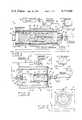
- FIG. 1is a longitudinal vertical cross-sectional view taken through a blood pressure cuff testing apparatus according to the present invention, shown with a typical cuff mounted for testing.
- FIG. 2is an end elevational view taken substantially on line 2--2 of FIG. 1.
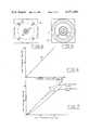
- FIG. 3is a horizontal cross-sectional view taken through a pressure chamber containing the cuff supporting member of FIG. 1, for determining the pressure-response characteristic curve of the supporting member without a cuff, to be employed for comparison with the pressure transmission curve obtained by the apparatus of FIG. 1.
- FIG. 4is a transverse vertical cross-sectional view taken substantially on line 4--4 of FIG. 3.
- FIG. 5is a transverse vertical cross-sectional view taken substantially on line 5--5 of FIG. 3.
- FIG. 6is a typical pressure response curve for the cuff supporting member alone, obtained from the chamber of FIG. 3.
- FIG. 7is a set of pressure-transmission curves obtained from the apparatus of FIG. 1.
- the testing support 11generally designates a cuff-testing support forming part of a cuff calibrating system according to the present invention.
- the testing support 11comprises an elongated base plate 12. Secured on one end of base plate 12 is an angle bracket 13 provided with the upstanding vertical arm 14.
- An elongated supporting block 15has an axial threaded stud 16 which is threadedly engaged through arm 14 and is thus horizontally supported above and parallel to base plate 12.
- the elongated block 15is circular in cross-section and is annularly recessed for the major portion of its length, as shown at 17, to define enlarged opposite end head members 18 and 19.
- the outer head member 18is formed with an axial boss 20.
- a thin flexible membrane sleeve 22Tightly and sealingly secured on the head members 18 and 19 and extending for the full length of the block 15 is a thin flexible membrane sleeve 22, of thin plastic material, or the like, which sealingly encloses the space in the elongated annular recess 17. Said space is filled with an incompressible medium 21, such as oil, water, or other liquid suitable for transmitting pressure applied to the outer surface of flexible sleeve 22.
- an incompressible medium 21such as oil, water, or other liquid suitable for transmitting pressure applied to the outer surface of flexible sleeve 22.
- the intermediate portion of block 15is formed with a diametrical bore 23 communicating with an axial bore 24 extending through the rightward portion of the block, as viewed in FIG. 1, and through stud 16, being connected by a conventional fitting 25, a tubular conduit 26, and a 2-way valve to a conventional pressure transducer 27.
- a blood pressure cuff 28which is to be tested for its pressure-transmitting characteristics, is placed on the sleeve 22 adjacent to the head portion 19, as shown, and is connected via its air input conduit 29 and a check valve 38 to a suitable fluid pressure source 30, such as an air pump, or the like.
- a second conventional pressure transducer 31is connected to the air supply conduit via a suitable connection tube 32.
- the electrical output terminal line conductors of the first pressure transducer 27are connected via a cable 33 to the Y-input terminals of a conventional X-Y recorder 34.
- the electrical output terminals of the second pressure transducer 31are connected to the X-input terminals of recorder 34 via a cable 35.
- a rigid restraining tube 36which is of sufficient length to substantially cover the portion of sleeve 22 between the leftward peripheral rim of cuff 28, as viewed in FIG. 1, and the leftward end of head member 18, whereby to prevent bulging under pressure of the portion of sleeve 22 not engaged by the cuff 28.
- the transducer 31When fluid pressure from the source 30 is applied to the wrapped cuff 28, the transducer 31 furnishes an electrical signal corresponding to such pressure via cable 35 to the X terminals of recorder 34.
- the resultant cuff pressureis transmitted via the sleeve 22, the incompressible liquid 21, passages 23 and 24, fitting 25 and conduit 26 to the pressure transducer 27, which thereby furnishes a Y-signal to the Y terminals of recorder 34.
- a corresponding traceis recorded by the recorder 34, showing the pressure transmitted to the transducer 27 as a function of the pressure applied to the transducer 31.
- FIGS. 3, 4 and 5show a pressure chamber 40 which may be employed for this purpose.
- Chamber 40comprises a substantially cylindrical Plexiglas housing having a cylindrical longitudinal main wall 41 with a rigidly-secured rear end wall 43 and a square front end cover plate 54 secured to the front rim of cylindrical shell 41 by corner screws 49.
- a rubber sealing gasket 55is interposed between plate 54 and the rim of cylindrical wall 41.
- End wall 43is formed with a central cylindrical recess 46 which loosely receives the left end boss 20 and provides fluid clearance between said boss and the recess, as shown at 47.
- the fluid pressure source 30is connected to clearance space 47 via a 2-way valve 68, a conduit 48 and a conventional connection fitting 69. Stud 16 extends through central apertures in gasket 55 and cover plate 54 and is rigidly secured to cover plate 54 by a clamping nut 70.
- the bore 24is connected to the input port of the pressure transducer 27 via a conventional connection fitting 71, a 2-way valve 72 and a conduit 26'.
- Conduit 48is connected to the input of pressure transducer 31. The output of said transducer 31 supplies the X-signal to the X-Y recorder 34.
- FIG. 1The assembly of FIG. 1 is taken apart by disconnecting conduit 26 by unscrewing the fitting 25 from stud 16. A suitable plug may be employed to temporarily seal the outlet end of bore 24.
- the assemblycomprising block 15 and the parts mounted thereon, including the liquid 21, is then unscrewed from vertical arm 14, transferred to housing 40 and inserted therein after first removing cover plate 54 and rubber gasket 55, this being done by unscrewing the fastening screws 49.
- Boss 20is engaged in recess 46 and stud 16 is engaged through the registering central apertures provided in cover plate 54 and gasket 55, after which the clamping nut 70 is engaged on stud 16 and tightened.
- cover plate 54 and gasket 55are rigidly secured to the cylindrical shell 41 by the fastening screws 49 so as to sealingly clamp the gasket 55 against the rim of shell 41.
- the temporary plugmay then be removed from stud 16 and the input of the pressure transducer 27 may then be connected to stud 16 via conduit 26' and 2-valve 72, in place of the original conduit 26.
- the transducer 31When fluid pressure from source 30 is applied to the housing 40, the transducer 31 furnishes an electrical signal corresponding to such pressure via cable 35 to the X terminals of recorder 34.
- the resultant internal pressure developed in sleeve 22is transmitted via the incompressible liquid 21, passage 24, and conduit 26' to the pressure transducer 27, which thereby furnishes a Y-signal to the Y terminals of recorder 34.
- a corresponding trace 50(FIG. 6) is recorded by the recorder 34, showing the pressure transmitted by the sleeve 22 as a function of the pressure applied to the transducer 31.
- FIG. 7shows typical cuff pressure transmission curves 51, 52 obtained with a typical cuff 28, employing the apparatus of FIG. 1.
- Curve 51is obtained with the cuff loosely wrapped around the sleeve 22, arranged as in FIG. 1.
- Curve 52is obtained with the cuff tightly wrapped around sleeve 22.
- the curvesare characteristic of the particular cuff 28 under test, and are comparable with the curve 50 obtained with the apparatus of FIG. 3 for evaluation of the performance of the particular cuff under the known test conditions, as to the pressure-transmitting characteristics of the cuff.
- Such evaluationis useful in determining how well the individual cuff will operate and as to the freedom of the cuff from defects such as leakage, clogging, excessive stiffness, or the like, and for determining how much pressure from the cuff will be delivered to the surface of an appendage, such as a human arm or an animal limb.
- the calibration system above describedis not the equivalent of a simulated arm because it does not consider the mechanical properties of tissue. Its sole purpose is to determine the ability of a cuff to deliver its pressure to the surface of an appendage such as an arm. It allows the user to separate the equipment aspects of blood pressure measurement from the physiological aspects. It thus provides the cuff manufacturer, or cuff standards laboratory, with the capability of determining the cuff characteristics at the time of manufacture and for monitoring said characteristics during the working life of the cuff.
- a design considerationis the width of the system. If so desired, an individual system can be made for each cuff width commercially available. By providing a separate calibration system for each cuff width, the rigid anti-bulge tube 36 need not be used, enabling such artifacts as are produced by its presence to be also eliminated. However, a system capable of testing a range of cuff widths by employing appropriate-length anti-bulge tubes 36 has advantages with respect to economy.
Landscapes
- Health & Medical Sciences (AREA)
- Life Sciences & Earth Sciences (AREA)
- Cardiology (AREA)
- Physics & Mathematics (AREA)
- Biomedical Technology (AREA)
- Vascular Medicine (AREA)
- Engineering & Computer Science (AREA)
- Biophysics (AREA)
- General Health & Medical Sciences (AREA)
- Veterinary Medicine (AREA)
- Public Health (AREA)
- Physiology (AREA)
- Animal Behavior & Ethology (AREA)
- Surgery (AREA)
- Pathology (AREA)
- Heart & Thoracic Surgery (AREA)
- Medical Informatics (AREA)
- Molecular Biology (AREA)
- Chemical & Material Sciences (AREA)
- Analytical Chemistry (AREA)
- General Physics & Mathematics (AREA)
- Ophthalmology & Optometry (AREA)
- Dentistry (AREA)
- Measuring Pulse, Heart Rate, Blood Pressure Or Blood Flow (AREA)
Abstract
Description
Claims (10)
Priority Applications (1)
| Application Number | Priority Date | Filing Date | Title |
|---|---|---|---|
| US06/414,904US4471646A (en) | 1982-09-03 | 1982-09-03 | Blood pressure cuff calibration system |
Applications Claiming Priority (1)
| Application Number | Priority Date | Filing Date | Title |
|---|---|---|---|
| US06/414,904US4471646A (en) | 1982-09-03 | 1982-09-03 | Blood pressure cuff calibration system |
Publications (1)
| Publication Number | Publication Date |
|---|---|
| US4471646Atrue US4471646A (en) | 1984-09-18 |
Family
ID=23643511
Family Applications (1)
| Application Number | Title | Priority Date | Filing Date |
|---|---|---|---|
| US06/414,904Expired - Fee RelatedUS4471646A (en) | 1982-09-03 | 1982-09-03 | Blood pressure cuff calibration system |
Country Status (1)
| Country | Link |
|---|---|
| US (1) | US4471646A (en) |
Cited By (13)
| Publication number | Priority date | Publication date | Assignee | Title |
|---|---|---|---|---|
| US4891120A (en)* | 1986-06-06 | 1990-01-02 | Sethi Rajinder S | Chromatographic separation device |
| US5027641A (en)* | 1989-02-23 | 1991-07-02 | Costello Jr Leo F | Oscillometric non-invasive blood pressure simulator |
| EP0537715A1 (en)* | 1991-10-15 | 1993-04-21 | SpaceLabs Medical, Inc. | Automatic cuff for blood pressure measurement |
| US5301676A (en)* | 1990-12-18 | 1994-04-12 | Instrumentarium Corporation | Identification method for a cuff type in a non-invasive sphygmomanometer |
| US6568241B2 (en)* | 1999-01-11 | 2003-05-27 | Becton Dickinson And Company | Isolated calibration adapter for sterile pressure transducer |
| US20050074732A1 (en)* | 2003-10-02 | 2005-04-07 | Morris Gary Jay | Blood pressure simulation apparatus with tactile interface |
| US20050131307A1 (en)* | 2003-12-15 | 2005-06-16 | Ruiter Karl A. | Compact oscillometric blood pressure simulator |
| US6984212B1 (en)* | 2004-09-21 | 2006-01-10 | Health & Life Co., Ltd. | Electronic sphygmomanometer calibrating tool |
| RU2301020C2 (en)* | 2005-08-05 | 2007-06-20 | Федеральное государственное учреждение "Татарстанский центр стандартизации, метрологии и сертификации" | Device for checking automated sphygmomanometers |
| US20080077021A1 (en)* | 2006-09-27 | 2008-03-27 | Fka Distributing Co. D/B/A Homedics, Inc. | Blood Pressure Monitor Calibration Device And Method For Calibrating A Blood Pressure Monitor |
| RU2392847C2 (en)* | 2007-05-31 | 2010-06-27 | Владимир Михайлович Евстюхин | Device for sphigmomanometre check in manometric membrane, semiautomatic and automatic arterial pressure instruments |
| RU2393758C1 (en)* | 2008-11-11 | 2010-07-10 | Государственное образовательное учреждение высшего профессионального образования Казанский государственный технический университет им. А.Н. Туполева | Device for checking automated sphygmomanometres |
| RU2405423C1 (en)* | 2009-06-16 | 2010-12-10 | Государственное образовательное учреждение высшего профессионального образования Казанский государственный технический университет им. А.Н. Туполева | Imitation model of human hand for testing means of measuring blood pressure and heart rate |
Citations (9)
| Publication number | Priority date | Publication date | Assignee | Title |
|---|---|---|---|---|
| US3045470A (en)* | 1957-01-08 | 1962-07-24 | Lockheed Aircraft Corp | Pressure controller |
| US3107515A (en)* | 1961-06-02 | 1963-10-22 | Bendix Corp | Double tube manometer to calibrate pressure sensing instruments |
| US3459032A (en)* | 1967-07-06 | 1969-08-05 | Roger Gilmont Instr Inc | Manometer calibrating device and methods |
| US3527204A (en)* | 1965-05-28 | 1970-09-08 | Ibm | Pressure cuff system |
| US3715925A (en)* | 1971-10-26 | 1973-02-13 | E Miller | Miniature recording altimeter |
| US3765405A (en)* | 1971-10-29 | 1973-10-16 | Minnesota Mining & Mfg | Sphygmomanometer cuff |
| US3812844A (en)* | 1971-05-26 | 1974-05-28 | K Sokol | Apparatus for measuring blood pressure with corresponding cuff sections and indication ranges |
| US3868844A (en)* | 1973-05-11 | 1975-03-04 | Burton Klein | Dynamic arterial blood pressure simulator |
| SU928179A2 (en)* | 1980-03-11 | 1982-05-15 | Московское Ордена Ленина И Ордена Трудового Красного Знамени Высшее Техническое Училище Им. Н.Э.Баумана | Pressure oscillation generator |
- 1982
- 1982-09-03USUS06/414,904patent/US4471646A/ennot_activeExpired - Fee Related
Patent Citations (9)
| Publication number | Priority date | Publication date | Assignee | Title |
|---|---|---|---|---|
| US3045470A (en)* | 1957-01-08 | 1962-07-24 | Lockheed Aircraft Corp | Pressure controller |
| US3107515A (en)* | 1961-06-02 | 1963-10-22 | Bendix Corp | Double tube manometer to calibrate pressure sensing instruments |
| US3527204A (en)* | 1965-05-28 | 1970-09-08 | Ibm | Pressure cuff system |
| US3459032A (en)* | 1967-07-06 | 1969-08-05 | Roger Gilmont Instr Inc | Manometer calibrating device and methods |
| US3812844A (en)* | 1971-05-26 | 1974-05-28 | K Sokol | Apparatus for measuring blood pressure with corresponding cuff sections and indication ranges |
| US3715925A (en)* | 1971-10-26 | 1973-02-13 | E Miller | Miniature recording altimeter |
| US3765405A (en)* | 1971-10-29 | 1973-10-16 | Minnesota Mining & Mfg | Sphygmomanometer cuff |
| US3868844A (en)* | 1973-05-11 | 1975-03-04 | Burton Klein | Dynamic arterial blood pressure simulator |
| SU928179A2 (en)* | 1980-03-11 | 1982-05-15 | Московское Ордена Ленина И Ордена Трудового Красного Знамени Высшее Техническое Училище Им. Н.Э.Баумана | Pressure oscillation generator |
Cited By (19)
| Publication number | Priority date | Publication date | Assignee | Title |
|---|---|---|---|---|
| US4891120A (en)* | 1986-06-06 | 1990-01-02 | Sethi Rajinder S | Chromatographic separation device |
| US5027641A (en)* | 1989-02-23 | 1991-07-02 | Costello Jr Leo F | Oscillometric non-invasive blood pressure simulator |
| US5301676A (en)* | 1990-12-18 | 1994-04-12 | Instrumentarium Corporation | Identification method for a cuff type in a non-invasive sphygmomanometer |
| EP0537715A1 (en)* | 1991-10-15 | 1993-04-21 | SpaceLabs Medical, Inc. | Automatic cuff for blood pressure measurement |
| US5277187A (en)* | 1991-10-15 | 1994-01-11 | Spacelabs Medical, Inc. | Apparatus and method for improving the performance of an automatic blood pressure cuff |
| US6568241B2 (en)* | 1999-01-11 | 2003-05-27 | Becton Dickinson And Company | Isolated calibration adapter for sterile pressure transducer |
| US20050074732A1 (en)* | 2003-10-02 | 2005-04-07 | Morris Gary Jay | Blood pressure simulation apparatus with tactile interface |
| US20080118901A1 (en)* | 2003-10-02 | 2008-05-22 | Morris Gary J | Blood pressure simulation apparatus with tactile feedback |
| US7972141B2 (en) | 2003-10-02 | 2011-07-05 | Gary Jay Morris | Blood pressure simulation apparatus with tactile feedback |
| US7320599B2 (en) | 2003-10-02 | 2008-01-22 | Gary Jay Morris | Blood pressure simulation apparatus with tactile interface |
| US20050131307A1 (en)* | 2003-12-15 | 2005-06-16 | Ruiter Karl A. | Compact oscillometric blood pressure simulator |
| WO2005058140A3 (en)* | 2003-12-15 | 2006-02-23 | Pronk Technologies Inc | Compact oscillometric blood pressure simulator |
| US20100076713A1 (en)* | 2003-12-15 | 2010-03-25 | Ruiter Karl A | Compact Oscillometric Blood Pressure Simulator |
| US6984212B1 (en)* | 2004-09-21 | 2006-01-10 | Health & Life Co., Ltd. | Electronic sphygmomanometer calibrating tool |
| RU2301020C2 (en)* | 2005-08-05 | 2007-06-20 | Федеральное государственное учреждение "Татарстанский центр стандартизации, метрологии и сертификации" | Device for checking automated sphygmomanometers |
| US20080077021A1 (en)* | 2006-09-27 | 2008-03-27 | Fka Distributing Co. D/B/A Homedics, Inc. | Blood Pressure Monitor Calibration Device And Method For Calibrating A Blood Pressure Monitor |
| RU2392847C2 (en)* | 2007-05-31 | 2010-06-27 | Владимир Михайлович Евстюхин | Device for sphigmomanometre check in manometric membrane, semiautomatic and automatic arterial pressure instruments |
| RU2393758C1 (en)* | 2008-11-11 | 2010-07-10 | Государственное образовательное учреждение высшего профессионального образования Казанский государственный технический университет им. А.Н. Туполева | Device for checking automated sphygmomanometres |
| RU2405423C1 (en)* | 2009-06-16 | 2010-12-10 | Государственное образовательное учреждение высшего профессионального образования Казанский государственный технический университет им. А.Н. Туполева | Imitation model of human hand for testing means of measuring blood pressure and heart rate |
Similar Documents
| Publication | Publication Date | Title |
|---|---|---|
| US4471646A (en) | Blood pressure cuff calibration system | |
| US3703099A (en) | Pressure transducer | |
| US3818765A (en) | Device for sterile measurement of liquid or gas pressures | |
| US5069219A (en) | Self snugging universal blood pressure cuff | |
| US4727750A (en) | Steam leakage measuring device | |
| US5103832A (en) | Biological pressure transducer zeroing and levelling reference apparatus | |
| JP2736195B2 (en) | Connector for catheter adapter | |
| US2600324A (en) | Fluid pressure measuring apparatus | |
| US3099262A (en) | Physiologic fluid pressure sensing head | |
| US4610256A (en) | Pressure transducer | |
| JPS6368133A (en) | Method and apparatus for compensating position of transducer of blood pressure monitor apparatus | |
| US4733555A (en) | Pressure entry and test system | |
| US3570474A (en) | Apparatus for quantitative indicating of small and rapid volume changes in a part of an extremity | |
| EP0078312A1 (en) | DEVICE FOR MONITORING PRESSURE SIZES. | |
| US4036216A (en) | Body fluid pressure system | |
| US7819811B2 (en) | Detecting medical conditions with noninvasive body probes | |
| US3662743A (en) | Pressure transducer for catheter pressure measurement | |
| US3122136A (en) | Catheter pressure standard | |
| US5195536A (en) | Self-adhering noninvasive intracorporeal movement detector | |
| US5772596A (en) | Osteoporosis apparatus | |
| EP0661529A3 (en) | Procedure and device for leak testing of a volume and for determining the leaking amount. | |
| US4854157A (en) | Device for measuring effective porosity | |
| Wiig et al. | Measurement of colloid osmotic pressure in submicrolitre samples | |
| US4715230A (en) | Pressure reducing instrument for pressure gauges | |
| CN207717289U (en) | A kind of electronic sphygmomanometer static pressure measurement special joint |
Legal Events
| Date | Code | Title | Description |
|---|---|---|---|
| AS | Assignment | Owner name:UNITED STATES OF AMERICA AS REPRESENTED BY THE SEC Free format text:ASSIGNMENT OF ASSIGNORS INTEREST.;ASSIGNOR:WALKER, ELIJAH C.;REEL/FRAME:004042/0668 Effective date:19820830 Owner name:UNITED STATES OF AMERICA AS REPRESENTED BY THE SEC Free format text:ASSIGNMENT OF ASSIGNORS INTEREST;ASSIGNOR:WALKER, ELIJAH C.;REEL/FRAME:004042/0668 Effective date:19820830 | |
| FEPP | Fee payment procedure | Free format text:PAYOR NUMBER ASSIGNED (ORIGINAL EVENT CODE: ASPN); ENTITY STATUS OF PATENT OWNER: LARGE ENTITY | |
| FPAY | Fee payment | Year of fee payment:4 | |
| AS | Assignment | Owner name:GRISWOLD MACHINE AND ENGINEERING, INC., A MI CORP. Free format text:ASSIGNMENT OF ASSIGNORS INTEREST.;ASSIGNOR:PIPEMASTER, INC., A CORP. OF UT;REEL/FRAME:005722/0001 Effective date:19901217 | |
| REMI | Maintenance fee reminder mailed | ||
| LAPS | Lapse for failure to pay maintenance fees | ||
| FP | Lapsed due to failure to pay maintenance fee | Effective date:19921020 | |
| STCH | Information on status: patent discontinuation | Free format text:PATENT EXPIRED DUE TO NONPAYMENT OF MAINTENANCE FEES UNDER 37 CFR 1.362 |