US4470089A - Tape unit cleaning device - Google Patents
Tape unit cleaning deviceDownload PDFInfo
- Publication number
- US4470089A US4470089AUS06/332,822US33282281AUS4470089AUS 4470089 AUS4470089 AUS 4470089AUS 33282281 AUS33282281 AUS 33282281AUS 4470089 AUS4470089 AUS 4470089A
- Authority
- US
- United States
- Prior art keywords
- reel
- cleaning
- capstan
- ribbon
- pinch roller
- Prior art date
- Legal status (The legal status is an assumption and is not a legal conclusion. Google has not performed a legal analysis and makes no representation as to the accuracy of the status listed.)
- Expired - Lifetime
Links
- 238000004140cleaningMethods0.000titleclaimsabstractdescription93
- 239000007788liquidSubstances0.000claimsabstractdescription18
- 210000003813thumbAnatomy0.000claimsdescription9
- 239000013536elastomeric materialSubstances0.000claimsdescription3
- 230000002708enhancing effectEffects0.000claims2
- 239000002904solventSubstances0.000abstract1
- 230000009471actionEffects0.000description3
- 239000000463materialSubstances0.000description3
- 229920000742CottonPolymers0.000description2
- PPBRXRYQALVLMV-UHFFFAOYSA-NStyreneChemical compoundC=CC1=CC=CC=C1PPBRXRYQALVLMV-UHFFFAOYSA-N0.000description2
- 239000012530fluidSubstances0.000description2
- 230000003993interactionEffects0.000description2
- 239000002184metalSubstances0.000description2
- 229920004943Delrin®Polymers0.000description1
- 229910000639Spring steelInorganic materials0.000description1
- 230000002411adverseEffects0.000description1
- 230000006835compressionEffects0.000description1
- 238000007906compressionMethods0.000description1
- 238000013500data storageMethods0.000description1
- 230000000694effectsEffects0.000description1
- 229910044991metal oxideInorganic materials0.000description1
- 150000004706metal oxidesChemical class0.000description1
- 238000000034methodMethods0.000description1
- 238000012986modificationMethods0.000description1
- 230000004048modificationEffects0.000description1
- 229920003023plasticPolymers0.000description1
- 229920001084poly(chloroprene)Polymers0.000description1
- 230000008569processEffects0.000description1
Images

Classifications
- G—PHYSICS
- G11—INFORMATION STORAGE
- G11B—INFORMATION STORAGE BASED ON RELATIVE MOVEMENT BETWEEN RECORD CARRIER AND TRANSDUCER
- G11B23/00—Record carriers not specific to the method of recording or reproducing; Accessories, e.g. containers, specially adapted for co-operation with the recording or reproducing apparatus ; Intermediate mediums; Apparatus or processes specially adapted for their manufacture
- G11B23/02—Containers; Storing means both adapted to cooperate with the recording or reproducing means
- G11B23/04—Magazines; Cassettes for webs or filaments
- G11B23/049—Cassettes for special applications not otherwise provided for
Definitions
- This inventionrelates to an improved cleaning device for cleaning rotatable elements such as capstans and pinch rollers of tape recording and playback equipment.
- tape unitwill be used in its broad sense to encompass equipment for recording or playing back audio, video, digital data storage, or other magnetic tapes.
- rotatable elementssuch as capstans and pinch rollers may build up deposits of materials such as metal oxides removed from magnetic tapes.
- depositscan materially and adversely affect the performance of tape units.
- deposits on capstans and pinch rollerscan interfere with the smooth and constant speed movement of magnetic tape in a tape unit.
- such depositscan cause a tape unit to jam or physically damage a magnetic tape being played.
- the present inventionis directed to an improved, self-contained cleaning unit which can simply be used and which can readily be designed to operate effectively with pinch rollers of varying geometries in order to provide adequate cleaning of capstans and pinch rollers.
- a housingis provided with a supply reel and a cleaning ribbon wound on the reel.
- the cleaning ribbonis positioned in the housing to come into contact with at least one rotatable element of a tape unit, and the cleaning ribbon can readily be advanced when desirable or necessary to present a fresh, clean portion of the cleaning ribbon to the rotatable element.
- This aspect of the inventionprovides a conveniently renewable cleaning surface, in that the cleaning ribbon can be advanced as necessary to ensure proper cleaning action.
- At least one traction sleeveis provided.
- This traction sleeveis mounted in the housing so as to surround a capstan when the housing is placed in a tape unit.
- the traction sleeveis designed to come between the capstan and the pinch roller in order to enhance the frictional engagement between the capstan and the pinch roller.
- the traction sleeves of this inventionoperate to overcome this disadvantage by providing an engagement area between the capstan and the traction sleeve which is protected from contact with cleaning liquids.
- the capstan-traction sleeve interaction areais kept dry, and the frictional engagement between the capstan and the traction sleeve is kept at a suitably high value.
- the traction sleeveis made of an elastomeric material chosen such that, even when wetted by cleaning liquids, the friction between the traction sleeve and the pinch roller is adequate to enable the capstan to rotate the pinch roller. In this way, adequate rotation of the pinch roller is obtained, even in the presence of cleaning liquids, and cleaning of the pinch roller is enhanced.
- a preferred embodiment of this inventionutilizes two separate traction sleeves of differing configurations in order effectively to clean capstans and pinch rollers that vary in geometry.
- the traction sleeve aspect of this inventionenables the capstan to rotate the pinch roller, even under considerable frictional loading.
- the traction sleeve of this inventionenables the use of a spring biased swabbing plunger to press a cleaning medium (such as the cleaning ribbon described above), against the pinch roller as the pinch roller is being rotated by the capstan. In this way, excellent cleaning of the pinch roller is obtained.
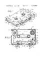
- FIG. 1is a perspective view in partial cutaway of the presently preferred embodiment of this invention.
- FIG. 2is a sectional view taken along line 2--2 of FIG. 1.
- FIG. 3is a detailed sectional view taken in the plane of FIG. 2 showing the swabbing plunger and the first traction sleeve of the embodiment of FIG. 1.
- FIG. 4is a fragmentary perspective view of the first traction sleeve shown in FIG. 3.
- FIG. 5is a detailed sectional view taken in the plane of FIG. 2 showing the second traction sleeve of the embodiment of FIG. 1.
- FIG. 6is a fragmentary perspective view of the section traction sleeve of FIG. 5.
- FIGS. 1 and 2show overall views of the presently preferred embodiment of this invention.
- this embodimentincludes a housing 10, which can for example be dimensioned and shaped as a standard cassette shell.
- the shell 10is shown as a Phillips type cassette, the invention can readily be adapted to other types of cassettes, such as Beta, VHS, and the like.
- the shape and size of the housingshould be chosen to fit the particular tape unit to be cleaned.
- the cassette shell 10is made of two partial sections 12,14 which are held together at the corners by fasteners 15.
- two hubs 16,18are rotatably mounted in the shell 10. These two hubs 16,18 are coupled together by means of a belt 20. As will be apparent from the following description, the hubs 16,18 and belt 20 perform no cleaning function in the cleaning apparatus of this invention. Rather, they serve to defeat the automatic shut-off circuitry found in many tape units in order to enable the tape unit to operate normally in the absence of a tape being transported by the capstans and pinch rollers.
- the second section 14 of the shell 10defines first and second axles 22,24 positioned as shown.
- the second section 14defines a number of support surfaces 26 which are positioned to support and orient a cleaning ribbon 80, as will be described in detail below.
- This second section 14 of the shell 10also defines a plunger mounting structure 28, plunger guides 30,32,34, as well as pawl mounting structure 36.
- Two traction sleeve retaining posts 40,42both having a generally crescent shaped cross-section, are also provided as part of the second section 14.
- the second traction sleeve retaining post 42cooperates with and is positioned adjacent to a traction sleeve vertical positioning surface 44 defined by the first section 12 of the shell 10. The function and operation of these elements of the device will be described below in detail in conjunction with FIGS. 3 through 6.
- the shell 10also defines means for introducing a liquid, such as a cleaning liquid for example, onto the cleaning ribbon 80.
- This meanscomprises two funnel-shaped openings 46,48 which pass through the first section 12 of the shell 10.
- the second section 14 of the shell 10defines two distribution channels 50,52, each of which is crescent shaped in cross-section and extends between the first and second sections 12,14.
- Each of distribution channels 50,52defines a central bore 54,56 which is open along one edge and which is aligned with and in fluid communication with the respective funnel-shaped opening 46,48.
- fluid introduced into the shell 10 via the funnel-shaped openings 46,48passes into the bores 54,56 of the distribution channels 50,52.
- liquidpasses directly from the bores 54, 56 onto the cleaning ribbon 80.
- a supply reel 60is rotatably mounted on the axle 22, and a take-up reel 62 is rotatably mounted on the axle 24.
- the outermost periphery of the take-up reel 62defines a plurality of ratchet teeth which cooperate with a ratchet pawl 66 mounted in the pawl mounting structure 36 on the second section 14 of the shell 10.
- the ratchet teeth on the circumference of the take-up reel 62also are accessible from the outside of the shell 10 and function as a thumb wheel 64.
- the ratchet teeth and the ratchet pawl 66cooperate to restrict the rotational movement of the take-up reel 62 to a forward direction (clockwise as seen in FIG. 2).
- a movable swabbing plunger 70is mounted in the plunger mounting structure 28 so as to move in a rectilinear manner, as guided by the plunger guides 30, 32,34.
- the tip 72 of the plunger 70is positioned adjacent the traction sleeve retaining post 40.
- a spring 74is mounted between the plunger mounting structure 28 and the plunger 70 so as to bias the plunger 70 away from the plunger mounting structure 28.
- a cleaning ribbon 80is wound on the supply reel 60 and the take-up reel 62 shown in FIG. 2.
- This cleaning ribbon 80extends from the supply reel 60, around the support surfaces 26, the distribution channels 50,52, to the take up reel 62.
- Rotation of the thumb wheel in the positive directioncauses the ribbon 80 to advance in the housing from the supply reel 60 to the take-up reel 62.
- As the ribbon 80 advances, clean portions of the ribbon 80are brought adjacent the plunger 70 and the traction sleeve retaining post 42.
- the ratchet pawl 66simultaneously serves to prevent the take-up reel 62 from rotating in a reverse direction, and to provide a series of audible clicks which can be used to gauge the advancement of the cleaning ribbon 80.
- the embodiment shown in the drawingsalso includes two traction sleeves 90,92.
- the first traction sleeve 90is mounted over the traction sleeve retaining post 40 such that the traction sleeve 90 fits the retaining post 40 closely, yet is free to rotate.
- the traction sleeve 90is relatively wide and extends over substantially the entire width of the cleaning ribbon 80, in alignment therewith.
- the circumference of the traction sleeve 90should be small enough to prevent the sleeve 90 from becoming entangled with or jammed in the ribbon 80, yet large enough to permit the sleeve 90 to rotate about the retaining post 40.
- the second traction sleeve 92differs from the first in that it is substantially larger in circumference and is positioned out of alignment with the ribbon 80.
- the larger circumference of the second traction sleeve 92is possible because jamming of the traction sleeve 92 is less of a problem, due to the fact that it is offset with respect to the cleaning ribbon 80.
- the vertical positioning surface 44serves to retain the second traction sleeve 92 in its offset position.
- the shell 10can be formed of any suitable material, such as a medium impact styrene for example.
- moving partssuch as the reels 60,62, the hubs 18,20, and the plunger 70 are formed of a plastic material such as Delrin.
- both the traction sleeves 90,92 and the belt 20are formed of an elastomeric material such as neoprene having a 60 durometer rating.
- the first traction sleeve 90has an inner diameter of about 0.279 inches, a height of about 0.173 inches, and a thickness of 0.020 inches.
- the second traction sleeve 92has an inner diameter of about 0.300 inches, a height of about 0.104 inches, and a thickness of about 0.035 inches.
- the pawl 66is preferably made of a strip of spring steel.
- the cleaning ribbon 80 of this preferred embodimentis a cotton ribbon having a width of about 3/16 of an inch and a thickness of about 0.015 inch under compression.
- a suitable cotton ribbonis sold by Jean Ribbon Mills of Passaic, N.J. as part No. 8820.
- the shell 10is inserted into a tape unit such that a capstan 100,102 (if present) is inserted within each of the traction sleeves 90,92, respectively.
- the cleaning device of this inventionis preferably used with the cleaning ribbon 80 in a stationary position and the capstans 100,102 and pinch rollers 104,106 of the tape unit in rotary motion.
- FIG. 3shows a sectional view of the portion of the preferred embodiment around the first traction sleeve 90 in use.
- the capstan 100fits within the traction sleeve 90, and the traction sleeve 90 is disposed between the capstan 100 and the adjacent pinch roller 104.
- the cleaning ribbon 80extends against the distribution channel 50 adjacent the bore 54 such that liquid introduced into the bore 54 is distributed along the entire width of the cleaning ribbon 80 adjacent the pinch roller 104.
- the spring biased plunger 70operates to push the cleaning ribbon 80 against the pinch roller 104.
- the pinch roller 104is caused to rotate against the portion of the ribbon 80 adjacent the plunger tip 72. Cleaning liquids travel from the distribution channel 50 to the region of the ribbon 80 adjacent the plunger tip 72 in order to facilitate cleaning.
- the traction sleeve 90insures positive frictional engagement between the capstan 100 and the pinch roller 104, while the plunger 70 insures that adequate swabbing pressure is exerted on the ribbon 80 against the pinch roller 104. It will be noted that the traction sleeve 90 entirely surrounds the capstan 100 and protects the capstan 100 from cleaning liquid on the ribbon 80. In this way, the interaction area between the capstan 100 and the traction sleeve 90 is kept dry to provide good frictional engagement between the metal capstan 100 and the elastomeric traction sleeve 90.
- FIG. 4shows a partial perspective view of the manner in which the traction sleeve 90 cooperates with the capstan 100, the pinch roller 104, the ribbon 80, and the plunger 70.
- the second traction sleeve 92operates in a somewhat different manner.
- the ribbon 80extends between the capstan 102 and the pinch roller 106.
- the traction sleeve 92which is offset with respect to the ribbon 80
- the distribution channel 52which conducts cleaning liquid via the bore 56 to the ribbon 80 adjacent the pinch roller 106.
- tape unitshave various styles and types of pinch rollers, and that tape units can either include tape guides adjacent the pinch rollers or not.
- the two cleaning stations adjacent the two traction devices 90,92have been particularly designed so that most of the commonly used configurations of pinch rollers will be cleaned by at least one of the two cleaning stations.
- the cleaning station adjacent the traction sleeve 90operates particularly well with thin pinch rollers and with pinch rollers that do not employ tape guides. This is because the traction sleeve 90 extends over substantially the full width of the normal magnetic tape, and thus frictional engagement between the traction sleeve 90 and the pinch roller 104 is insured.
- This first cleaning stationoperates to clean the pinch roller 104 but not the capstan 100 in view of the fact that the traction sleeve 90 completely protects the capstan 100 from contact with the ribbon 80.
- the second cleaning station adjacent the traction sleeve 92operates well with pinch rollers having tape guides. This is because the ribbon 80 passes directly between the capstan 102 and the pinch roller 106, and therefore is not obstructed by the presence of tape guides. Furthermore, the second cleaning station adjacent traction sleeve 92 operates simultaneously to clean both the capstan 102 and the pinch roller 106.
- both of the capstans 100,102 and pinch rollers 104,106are positioned at both cleaning stations.
- the embodiment described aboveprovides a number of important advantages. It provides a simple, self-contained system which allows the cleaning ribbon 80 to be advanced when necessary to provide a fresh cleaning surface. In addition, it provides means for positively rotating the pinch rollers in order to provide excellent pinch roller cleaning against the ribbon 80. The differences in the two cleaning stations enable this device to work well with a wide variety of geometries and configurations of pinch rollers and tape guides. Futhermore, the spring biased plunger and the distribution channels provide improved cleaning action.
Landscapes
- Impression-Transfer Materials And Handling Thereof (AREA)
Abstract
Description
Claims (31)
Priority Applications (1)
| Application Number | Priority Date | Filing Date | Title |
|---|---|---|---|
| US06/332,822US4470089A (en) | 1981-12-21 | 1981-12-21 | Tape unit cleaning device |
Applications Claiming Priority (1)
| Application Number | Priority Date | Filing Date | Title |
|---|---|---|---|
| US06/332,822US4470089A (en) | 1981-12-21 | 1981-12-21 | Tape unit cleaning device |
Publications (1)
| Publication Number | Publication Date |
|---|---|
| US4470089Atrue US4470089A (en) | 1984-09-04 |
Family
ID=23300003
Family Applications (1)
| Application Number | Title | Priority Date | Filing Date |
|---|---|---|---|
| US06/332,822Expired - LifetimeUS4470089A (en) | 1981-12-21 | 1981-12-21 | Tape unit cleaning device |
Country Status (1)
| Country | Link |
|---|---|
| US (1) | US4470089A (en) |
Cited By (15)
| Publication number | Priority date | Publication date | Assignee | Title |
|---|---|---|---|---|
| DE3523425A1 (en)* | 1985-06-29 | 1986-03-06 | PMT Pro-Media Technics GmbH, 4006 Erkrath | Cleaning cassette for cassette-operated magnetic tape devices |
| US4635156A (en)* | 1982-09-13 | 1987-01-06 | Staar, S.A. | Cleaning cassette for magnetic tape apparatus |
| US4674000A (en)* | 1984-07-05 | 1987-06-16 | Lee Jeen Ju | Cleaning device for the magnetic heads of video tape recorders |
| US4692830A (en)* | 1983-06-22 | 1987-09-08 | Ulrich Willburger | Cleaning cassette for high speed cassette recorders including manually operable drive means |
| US4722016A (en)* | 1983-09-19 | 1988-01-26 | Olympus Optical Co., Ltd. | Tape cassette for cleaning use |
| EP0262620A1 (en)* | 1986-09-30 | 1988-04-06 | Tandberg Data A/S | Cleaning cassette for a magnetic-tape apparatus |
| EP0223529A3 (en)* | 1985-11-13 | 1989-04-19 | Recoton Corporation | Audio adaptor |
| US4849843A (en)* | 1986-06-27 | 1989-07-18 | Tdk Corporation | Demagnetizer for a magnetic head of a cassette tape recorder |
| US4938586A (en)* | 1984-12-07 | 1990-07-03 | Canon Kabushiki Kaisha | Information projecting apparatus |
| WO1994028547A1 (en)* | 1993-05-25 | 1994-12-08 | Griffin Edward E | Magnetic tape recording head cleaning apparatus |
| US5392183A (en)* | 1993-11-29 | 1995-02-21 | Rayis; Yousif I. | Service cassette extension for video cassette recorder, player and camera |
| US5467238A (en)* | 1993-07-06 | 1995-11-14 | Quantum Corporation | Cleaning apparatus for heads of data storage disks |
| US5586090A (en)* | 1994-11-18 | 1996-12-17 | Gemini Industries, Inc. | Adapter for playback of signals from an audio device |
| US6097572A (en)* | 1998-01-29 | 2000-08-01 | Geneva Group Of Companies, Inc. | Tape drive head cleaning cartridge having a cleaning element with cleaning segments extending above and below a cleaning tape |
| US6292330B1 (en) | 1998-01-29 | 2001-09-18 | Geneva Group Of Companies, Inc. | Magnetic head cleaning cartridge with displaceable head receiver |
Citations (3)
| Publication number | Priority date | Publication date | Assignee | Title |
|---|---|---|---|---|
| US3955214A (en)* | 1974-08-26 | 1976-05-04 | Tobins Industries Corporation | Device for cleaning the magnetic head and capstan roller of a cassette-type recording and/or playback unit in response to operation of the tape drive of the unit |
| US3961375A (en)* | 1974-07-15 | 1976-06-01 | Teletype Corporation | Apparatus for cleaning an informational tape |
| US4388663A (en)* | 1979-11-10 | 1983-06-14 | Konig-Electronic Friedrich W. Konig | Cleaning cassette for a tape machine |
- 1981
- 1981-12-21USUS06/332,822patent/US4470089A/ennot_activeExpired - Lifetime
Patent Citations (3)
| Publication number | Priority date | Publication date | Assignee | Title |
|---|---|---|---|---|
| US3961375A (en)* | 1974-07-15 | 1976-06-01 | Teletype Corporation | Apparatus for cleaning an informational tape |
| US3955214A (en)* | 1974-08-26 | 1976-05-04 | Tobins Industries Corporation | Device for cleaning the magnetic head and capstan roller of a cassette-type recording and/or playback unit in response to operation of the tape drive of the unit |
| US4388663A (en)* | 1979-11-10 | 1983-06-14 | Konig-Electronic Friedrich W. Konig | Cleaning cassette for a tape machine |
Non-Patent Citations (2)
| Title |
|---|
| U Matic Recorder Cleaner Instructions.* |
| U-Matic Recorder Cleaner Instructions. |
Cited By (18)
| Publication number | Priority date | Publication date | Assignee | Title |
|---|---|---|---|---|
| US4635156A (en)* | 1982-09-13 | 1987-01-06 | Staar, S.A. | Cleaning cassette for magnetic tape apparatus |
| US4692830A (en)* | 1983-06-22 | 1987-09-08 | Ulrich Willburger | Cleaning cassette for high speed cassette recorders including manually operable drive means |
| US4722016A (en)* | 1983-09-19 | 1988-01-26 | Olympus Optical Co., Ltd. | Tape cassette for cleaning use |
| US4674000A (en)* | 1984-07-05 | 1987-06-16 | Lee Jeen Ju | Cleaning device for the magnetic heads of video tape recorders |
| US4938586A (en)* | 1984-12-07 | 1990-07-03 | Canon Kabushiki Kaisha | Information projecting apparatus |
| DE3523425A1 (en)* | 1985-06-29 | 1986-03-06 | PMT Pro-Media Technics GmbH, 4006 Erkrath | Cleaning cassette for cassette-operated magnetic tape devices |
| EP0223529A3 (en)* | 1985-11-13 | 1989-04-19 | Recoton Corporation | Audio adaptor |
| US4849843A (en)* | 1986-06-27 | 1989-07-18 | Tdk Corporation | Demagnetizer for a magnetic head of a cassette tape recorder |
| US4763216A (en)* | 1986-09-30 | 1988-08-09 | Tandberg Data A/S | Cleaning cassette for a magnetic tape recorder means |
| EP0262620A1 (en)* | 1986-09-30 | 1988-04-06 | Tandberg Data A/S | Cleaning cassette for a magnetic-tape apparatus |
| WO1994028547A1 (en)* | 1993-05-25 | 1994-12-08 | Griffin Edward E | Magnetic tape recording head cleaning apparatus |
| US5748418A (en)* | 1993-05-25 | 1998-05-05 | Geneva Group Of Companies, Inc. | Magnetic tape recording head cleaning apparatus |
| US5467238A (en)* | 1993-07-06 | 1995-11-14 | Quantum Corporation | Cleaning apparatus for heads of data storage disks |
| US5486970A (en)* | 1993-07-06 | 1996-01-23 | Quantum Corporation | Cleaning apparatus for heads of data storage disks |
| US5392183A (en)* | 1993-11-29 | 1995-02-21 | Rayis; Yousif I. | Service cassette extension for video cassette recorder, player and camera |
| US5586090A (en)* | 1994-11-18 | 1996-12-17 | Gemini Industries, Inc. | Adapter for playback of signals from an audio device |
| US6097572A (en)* | 1998-01-29 | 2000-08-01 | Geneva Group Of Companies, Inc. | Tape drive head cleaning cartridge having a cleaning element with cleaning segments extending above and below a cleaning tape |
| US6292330B1 (en) | 1998-01-29 | 2001-09-18 | Geneva Group Of Companies, Inc. | Magnetic head cleaning cartridge with displaceable head receiver |
Similar Documents
| Publication | Publication Date | Title |
|---|---|---|
| US4470089A (en) | Tape unit cleaning device | |
| US4580185A (en) | Video player/recorder cleaning apparatus and method | |
| US4462056A (en) | Video tape recorder cleaning device | |
| US3674942A (en) | Magnetic recording and reproducing apparatus of cassette type | |
| US4141053A (en) | Magnetic tape head cleaning apparatus | |
| US3254856A (en) | Transducing machine | |
| US3758048A (en) | Tape cassette | |
| US4458281A (en) | Magnetic tape head cleaning apparatus | |
| US3860960A (en) | Magnetic recording and reproducing apparatus with tape extraction | |
| US4637088A (en) | Tape cleaning machine | |
| DE2018838A1 (en) | Tape recorder | |
| US5305162A (en) | Tape tensioning mechanism with tape loading-activated tensioning pin | |
| US3701178A (en) | Cassette tape cleaner | |
| US4498113A (en) | Apparatus and method for cleaning a video player/recorder | |
| US3925820A (en) | Endless loop tape cartridge for use with tape extraction systems | |
| US3958273A (en) | Cassette-type head demagnetizer | |
| EP0738415B1 (en) | Video player/recorder cleaning device | |
| US4683511A (en) | Head and guide cleaning device for video tape recorder | |
| US3559908A (en) | Endless tape cartridge | |
| US5430593A (en) | Head cleaning device utilizing a cleaning ribbon | |
| US4618896A (en) | Single message recorder and playback apparatus | |
| BE891096A (en) | CLEANING CASSETTE FOR MAGNETIC RECORDERS | |
| US4529149A (en) | Miniature video cassette | |
| US4813628A (en) | Slack limiter for a magnetic tape cassette | |
| JPS637936Y2 (en) |
Legal Events
| Date | Code | Title | Description |
|---|---|---|---|
| AS | Assignment | Owner name:INTERNATIONAL JENSEN INCORPORATED, SCHILLER PARK, Free format text:ASSIGNMENT OF ASSIGNORS INTEREST.;ASSIGNORS:HUTCHINS, BRUCE A.;FAY, RICHARD;REEL/FRAME:003970/0148 Effective date:19811207 | |
| STCF | Information on status: patent grant | Free format text:PATENTED CASE | |
| AS | Assignment | Owner name:INTERNATIONAL JENSEN INCORPORATED Free format text:MERGER;ASSIGNOR:INTERNATIONAL JENSEN INCORPORATED (MERGED INTO) BCI INTERNATIONAL JENSEN INCORPORATED (CHANGED TO);REEL/FRAME:004745/0010 Effective date:19870410 | |
| AS | Assignment | Owner name:DISCWASHER, INC., SCHILLER PARK, ILLINOIS, A CORP. Free format text:ASSIGNMENT OF ASSIGNORS INTEREST.;ASSIGNOR:INTERNATIONAL JENSEN INCORPORATED, A DE CORP.;REEL/FRAME:004767/0105 Effective date:19870921 Owner name:DISCWASHER, INC., A CORP. OF DE,ILLINOIS Free format text:ASSIGNMENT OF ASSIGNORS INTEREST;ASSIGNOR:INTERNATIONAL JENSEN INCORPORATED, A DE CORP.;REEL/FRAME:004767/0105 Effective date:19870921 | |
| FPAY | Fee payment | Year of fee payment:4 | |
| AS | Assignment | Owner name:HARRIS TRUST AND SAVINGS BANK, 111 WEST MONROE STR Free format text:SECURITY INTEREST;ASSIGNOR:DISCWASHER, INC.,;REEL/FRAME:004826/0369 Effective date:19870921 Owner name:MARINE VENTURE CAPITAL, INC., 111 EAST WISCONSIN A Free format text:SECURITY INTEREST;ASSIGNOR:DISCWASHER, INC.;REEL/FRAME:004844/0630 Effective date:19870921 Owner name:INTERNATIONAL JENSEN INCORPORATED, 4136 N. UNITED Free format text:SECURITY INTEREST;ASSIGNOR:DISCWASHER, INC.;REEL/FRAME:004844/0644 Effective date:19870921 Owner name:HARRIS TRUST AND SAVINGS BANK,ILLINOIS Free format text:SECURITY INTEREST;ASSIGNOR:DISCWASHER, INC.,;REEL/FRAME:004826/0369 Effective date:19870921 Owner name:MARINE VENTURE CAPITAL, INC., WISCONSIN Free format text:SECURITY INTEREST;ASSIGNOR:DISCWASHER, INC.;REEL/FRAME:004844/0630 Effective date:19870921 Owner name:INTERNATIONAL JENSEN INCORPORATED, ILLINOIS Free format text:SECURITY INTEREST;ASSIGNOR:DISCWASHER, INC.;REEL/FRAME:004844/0644 Effective date:19870921 | |
| FEPP | Fee payment procedure | Free format text:PAYOR NUMBER ASSIGNED (ORIGINAL EVENT CODE: ASPN); ENTITY STATUS OF PATENT OWNER: LARGE ENTITY Free format text:PAT HOLDER CLAIMS SMALL ENTITY STATUS - SMALL BUSINESS (ORIGINAL EVENT CODE: SM02); ENTITY STATUS OF PATENT OWNER: LARGE ENTITY | |
| FPAY | Fee payment | Year of fee payment:8 | |
| FEPP | Fee payment procedure | Free format text:PAT HLDR NO LONGER CLAIMS SMALL ENT STAT AS SMALL BUSINESS (ORIGINAL EVENT CODE: LSM2); ENTITY STATUS OF PATENT OWNER: LARGE ENTITY | |
| FPAY | Fee payment | Year of fee payment:12 | |
| AS | Assignment | Owner name:DISCWASHER, INC., ILLINOIS Free format text:PATENT COLLATERAL RELEASE ASSIGNMENT;ASSIGNOR:HARRIS TRUST AND SAVINGS BANK;REEL/FRAME:010377/0705 Effective date:19990523 Owner name:DISCWASHER, INC., ILLINOIS Free format text:PATENT COLLATERAL RELEASE AGREEMENT;ASSIGNOR:INTERNATIONAL JENSEN INCORPORATED;REEL/FRAME:010377/0710 Effective date:19910528 | |
| AS | Assignment | Owner name:DISCWASHER, INC., ILLINOIS Free format text:PATENT COLLATERAL RELEASE AGREEMENT;ASSIGNOR:BANC ONE VENTURE CORPORATION, FORMERLY KNOWN AS MARINE VENTURE CAPITAL, INC.;REEL/FRAME:010377/0591 Effective date:19910528 | |
| AS | Assignment | Owner name:RECOTON CORPORATION, FLORIDA Free format text:PATENT COLLATERAL RELEASE AGREEMENT;ASSIGNOR:DISCWASHER, INC.;REEL/FRAME:011137/0432 Effective date:19910528 | |
| AS | Assignment | Owner name:HELLER FINANCIAL, INC., ILLINOIS Free format text:SECURITY AGREEMENT;ASSIGNORS:RECOTON CORPORATION;INTERACT ACCESSORIES, INC.;AAMP OF FLORIDA, INC.;AND OTHERS;REEL/FRAME:011410/0372 Effective date:20001031 |