US4469450A - Electroacoustic method for nondestructively monitoring the internal temperature of objects - Google Patents
Electroacoustic method for nondestructively monitoring the internal temperature of objectsDownload PDFInfo
- Publication number
- US4469450A US4469450AUS06/383,426US38342682AUS4469450AUS 4469450 AUS4469450 AUS 4469450AUS 38342682 AUS38342682 AUS 38342682AUS 4469450 AUS4469450 AUS 4469450A
- Authority
- US
- United States
- Prior art keywords
- pulse
- internal temperature
- propogation
- relationship
- time
- Prior art date
- Legal status (The legal status is an assumption and is not a legal conclusion. Google has not performed a legal analysis and makes no representation as to the accuracy of the status listed.)
- Expired - Lifetime
Links
Images


Classifications
- G—PHYSICS
- G01—MEASURING; TESTING
- G01K—MEASURING TEMPERATURE; MEASURING QUANTITY OF HEAT; THERMALLY-SENSITIVE ELEMENTS NOT OTHERWISE PROVIDED FOR
- G01K11/00—Measuring temperature based upon physical or chemical changes not covered by groups G01K3/00, G01K5/00, G01K7/00 or G01K9/00
- G01K11/22—Measuring temperature based upon physical or chemical changes not covered by groups G01K3/00, G01K5/00, G01K7/00 or G01K9/00 using measurement of acoustic effects
- G01K11/24—Measuring temperature based upon physical or chemical changes not covered by groups G01K3/00, G01K5/00, G01K7/00 or G01K9/00 using measurement of acoustic effects of the velocity of propagation of sound
Definitions
- the present inventionrelates generally to a method for determining the internal temperature of objects having poor thermal conductance. More particularly, the present invention pertains to a method for monitoring the internal temperature of objects containing elastomeric materials, such as tires. More specifically, the present invention pertains to a method employing electroacoustics for nondestructively monitoring the internal temperature of a tire.
- the method of the present inventionwhich may utilize ultrasonics, can be practiced when the object, such as a tire is in actual operation, during heat induced curing by microwave frequency radiation, or at any other time.
- All techniques for monitoring the temperature of elastomeric containing objects, such as tiresmay be broadly said to fall into two categories, those where measurements are made external to the tire and those where measurements are made internal of the tire. Since elastomeric materials are poor thermal conductors, a measurement of the external surface temperature of a tire will not be equal to and will not necessarily accurately reflect the internal tire temperature. Nevertheless, external measurement techniques (such as the use of infrared sensors and thermocouple transducers coupled to the tire surface) are popular because they are nondestructive, leaving the tire in an otherwise usable condition after the temperature testing process is complete, and may be utilized to monitor tire temperature when the tire is mounted and in actual use. Moreover, models have been developed to predict internal temperatures during curing of a tire where conventional thermal conduction curing is employed.
- electroacousticsfor the determination of distance is well-known in many endeavors. Relying on the principle that for a constant temperature and pressure sound travels through a material at a substantially constant velocity (although this velocity differs for different materials), electroacoustic frequency (such as ultrasonic) pulses are generated and propogated through the material of interest, whereupon the distance the pulse traveled may be calculated by multiplying its velocity times the pulse propogation time.
- electroacoustic frequencysuch as ultrasonic
- an object of the present inventionto provide a method for accurately determining the internal temperature of objects having poor thermal conductance without destruction of the objects.
- a method for nondestructively monitoring the internal temperature of objects having poor thermal conductanceincludes the initial steps of determining the internal temperature of a reference object or a representative portion thereof at a plurality of internal temperatures (T), measuring a plurality of pulse propogation times (t T ) taken by an electroacoustic frequency pulse signal to propogate through the reference object or a representative portion thereof at the plurality of internal temperatures (T), and establishing a relationship between the determined plurality of internal temperatures (T) and the associated plurality of pulse propogation times (t T ).
- the unknown internal temperature (T U ) of the object to be monitoredmay be found by measuring the pulse propogation time (t TU ) taken by an electroacoustic frequency pulse signal to propogate therethrough and determining the unknown internal temperature (T U ) from correlating the measured pulse propogation time (t TU ) at the unknown internal temperature (T U ) to the relationship.
- the propogation paths in the sample object and object to be monitoredhave significantly different lengths, the aforesaid relationship may be made independent of the dimensions of both objects.
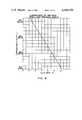
- FIG. 1is a block diagram of a testing apparatus, together with a transducer and a single layer reference sample, permitting implementation of the present invention.
- FIG. 2is a top plan view of a single layer reference sample.
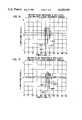
- FIG. 3is a graph of an exemplary internal temperature versus pulse propogation time relationship for a single layer reference sample as depicted in FIG. 2.
- FIG. 4is a graph of an exemplary internal temperature versus pulse propogation time ratio relationship for a single layer reference sample as depicted in FIG. 2.
- all elapsed times measured and plotted in FIG. 3have been normalized by division with an arbitrarily selected reference pulse propogation time of 10 microseconds ( ⁇ sec) which occurred when the internal temperature was 76° F. (24° C.).
- FIG. 5is a top plan view of a multiple layer reference sample.
- FIG. 6is a graph of an exemplary internal temperature versus pulse propogation time relationship for a multiple layer reference sample as depicted in FIG. 5.
- FIG. 7is a graph of an exemplary internal temperature versus pulse propogation time ratio relationship for a multiple layer reference sample as depicted in FIG. 5.
- all pulse propogation times measured and plotted in FIG. 6have been normalized by division with an arbitrarily selected reference pulse propogation time of 10 microseconds ( ⁇ sec) which occurred when the internal temperature was 76° F. (24° C.).
- FIG. 8is a somewhat schematic representation, as would be displayed by an oscilloscope, of the return ultrasonic pulse signal waveform as detected by the transducer when coupled with the multiple layer reference sample having an internal temperature within all layers of 70° F. (21° C.).
- the waveform of FIG. 8is an approximation and is not necessarily to scale or coordinated in time with the waveform in FIG. 9.
- FIG. 9is a somewhat schematic representation, as would be displayed by an oscilloscope, of the return ultrasonic pulse signal waveform as detected by the transducer when coupled with the multiple layer reference sample having an internal temperature within all layers of 125° F. (52° C.).
- the waveform of FIG. 9is an approximation and is not necessarily to scale or coordinated in time with the waveform in FIG. 8.
- FIG. 1illustrates a block diagram of an apparatus, generally demoninated by the numeral 12, which together with a transducer 14 of appropriate frequency response and a reference sample or object 16 is suitable for carrying out the method of the present invention providing nondestructive thermal analyses.
- a testing apparatus 12 in commercial useis identified as the Nova Scope 2000 available from NDT Instruments, Huntington Beach, Calif., with a typical transducer 14 taking the form of a Model C6-2.5 MHz ultrasonic transducer available from Harisonic Laboratories Inc. of Stamford, Conn.
- testing apparatus 12may also be comprised of discrete components as an ultrasonic pulse generator 18 and a receiver 20, such as the Metrotek MP215 pulser and MR101 receiver, both available from Metrotek Ultrasonic Instruments, Richland, Wash. Testing apparatus 12 may further include an oscilloscope 22, such as Tektronix Type 422 oscilloscope, available from Tektronix Inc. of Beaverton, Ore., together with a central processor unit (CPU) or desk top computer 24, such as the Intel Model 8010 desk-top computer, available from Intel Corporation of Santa Clara, Calif.
- CPUcentral processor unit
- desk top computersuch as the Intel Model 8010 desk-top computer, available from Intel Corporation of Santa Clara, Calif.
- a final component of testing apparatus 12could also include a display device 26 such as a seven-segment light emitting diode (LED) numeric readout, and a time counter such as a Tektronix Model DC505A counter.
- a display device 26such as a seven-segment light emitting diode (LED) numeric readout
- a time countersuch as a Tektronix Model DC505A counter.
- Reference sample or object 16may, for example, be a piece of cured, partially cured or green rubber stock such as a durometer test button.
- FIG. 2is a top plan view of an exemplary reference sample 16 of a single layer, with broken circle 28 indicating a typical placement thereupon of transducer 14.
- FIG. 5is a perspective view of a multiple layer reference sample 30 representing a typical section from the tread portion of a radial truck tire having an outer tread layer 32 of compounded rubber, a first reinforcing belt or layer 34 of a rubberized composition having embedded therein a plurality of parallel reinforcing cords 36 of textile, glass or steel constructions.
- a second belt or layer 38 of rubberalso has embedded therein a plurality of reinforcing cords 40.
- a third belt or layer of rubber 42has embedded therein reinforcing cords 44 while a fourth belt or layer of rubber material 46 has embedded therein a plurality of reinforcing cords 48.
- fourth belt or layer 46below but adjacent to fourth belt or layer 46 is a layer of body ply material 52 of a rubberized composition having a plurality of reinforcing cords 54, of textile, glass or steel material embedded therein. Finally, below body ply material 52 there is a layer of innerliner material 56 of a low-permeability rubber composition.
- the actual compositions, thicknesses or arrangements of the various belts or layers as well as the types of reinforcing cords and the various bias angles thereofare of no importance relative to the nondestructive monitoring method of the present invention and are shown for illustrative purposes only, with tread layer 32 being the outermost layer, i.e., the layer in actual contact with the ground.
- the method of the present inventionis straightforward. Essentially all that is necessary is to first determine the relationship between the time it takes an ultrasonic frequency pulse to propogate through the material of interest and its corresponding internal temperature. This need only be done with a single standard or reference sample (hereinafter called the “reference sample”). Thereafter, measurement at the same frequency with a transducer having similar characteristics of a “pulse propogation time” (hereinafter referred to as "PPT") on any similar object (hereinafter called the “monitored object”) may be directly correlated to the determined relationship, and its internal temperature thereby found without need for destructive measurement internal to the object.
- PPTpulse propogation time
- ultrasonic transducer 14operatively interconnected with apparatus 12, is coupled with reference sample 16 by placing it in physical contact with top surface 15 in the manner shown in FIGS. 1 and 2. Thereafter, an ultrasonic frequency pulse of sufficient energy to fully penetrate reference sample 16, reflect off its inner or bottom surface 17 and return to the transducer at its top or outer surface 15, is generated by generator 12.
- Receiver 20furnishes a waveform to CPU 24 and oscilloscope 22 from which the PPT may be directly discerned as explained further hereinbelow.
- PPTs(identified with the symbol t T ) are obtained for a plurality of desired or known internal temperatures (T), with verification of these temperatures, where required, being made via any conventional monitoring equipment capable of accurately measuring the internal temperature of the reference object.
- a graphmay be made as in FIG. 3 showing the relationship of PPT to internal temperature of reference sample 16.
- the instantaneous internal temperature of the monitored tiremay be found by measuring the instantaneous PPT and correlating this through the relationship in FIG. 3 to the actual internal temperature. For example, if at one instant in time the monitored tire stock is found by measurement to have a PPT of 13 ⁇ sec, the internal temperature of the tire stock at that instant in time may be found from the graph of FIG. 3 to be 120° F. (49° C.).
- computer 24may have this relationship stored in its memory and upon receipt of a PPT from receiver 20 automatically find the corresponding internal temperature and present it at LED numeric readout 26.
- the instantaneous internal temperature of the monitored tire stockmay be found by measuring the PPT for the monitored tire stock at some unknown internal temperature (T U ), which PPT may be identified as t TU , dividing this into the reference PPT so as to normalize t TU , and correlating this normalized PPT through the relationship in FIG. 4 to the actual internal temperature of the tire stock. For example, if a monitored tire stock of a type similar to that of the reference sample 16 utilized to gather the data for FIGS.
- the procedure for monitoring the internal temperature of objects having multiple layers therein as the radial truck tire section 30 shown in FIG. 5is substantially the same as for single layer objects as reference sample 16.
- each layer interfacewill result in a separate return echo to receiver 20, thereby providing a plurality of relationships between PPTs and internal temperature (as depicted in FIG. 6), and a similar plurality of relationships between normalized PPTs and internal temperature (as depicted in FIG. 7). From such relationships the instantaneous internal temperature of each layer may be monitored and a profile developed of temperature variations throughout the tire.
- FIGS. 8 and 9present exemplary return ultrasonic pulse signal waveforms as would be shown on the screen of oscilloscope 22 with transducer 14 coupled to multiple layer reference sample 30.
- PPTs for the four beltscan be seen from successive points of maximum amplitude to have occurred at approximately 24.5, 26, 27.5 and 30 ⁇ secs after the transmission of the ultrasonic pulse.
- PPTs for the four beltscan be similarly seen to have occurred at approximately 26.5, 28, 29.5 and 32.5 ⁇ secs after the transmission of the ultrasonic pulse.
- the method of the present inventionis not invasive to the monitored object, it will be appreciated that is is nondestructive and will cause minimal, if any, disturbance to any manufacturing process. Moreover, because this method can be completed in a fraction of a second, a continuous history of internal temperature changes may be developed. Since only external coupling of a transducer to the monitored object is required to effect the method of the present invention, the skilled artisan will understand that it may be applied to objects as tires in actual operation in addition to any manufacturing applications.
Landscapes
- Physics & Mathematics (AREA)
- Acoustics & Sound (AREA)
- General Physics & Mathematics (AREA)
- Investigating Or Analyzing Materials By The Use Of Ultrasonic Waves (AREA)
- Measuring Temperature Or Quantity Of Heat (AREA)
Abstract
Description
TABLE I ______________________________________ Internal Pulse Propogation PPT Temperature Time (PPT) Ratio ______________________________________ 76° F. (24° C.) 10.0μsecs 1 90° F. (32° C.) 10.6 μsecs 0.943 95° F. (35° C.) 10.8 μsecs 0.930 100° F. (38° C.) 11.6 μsecs 0.862 108° F. (42° C.) 12.2 μsecs 0.820 118° F. (48° C.) 12.8 μsecs 0.780 133° F. (56° C.) 14.0 μsecs 0.720 150° F. (66° C.) 14.6 μsecs 0.690 205° F. (96° C.) 19.0 μsecs 0.530 ______________________________________
Claims (12)
Priority Applications (8)
| Application Number | Priority Date | Filing Date | Title |
|---|---|---|---|
| US06/383,426US4469450A (en) | 1982-06-01 | 1982-06-01 | Electroacoustic method for nondestructively monitoring the internal temperature of objects |
| CA000426143ACA1191244A (en) | 1982-06-01 | 1983-04-19 | Electroacoustic method for nondestructively monitoring the internal temperature of objects |
| ZA833152AZA833152B (en) | 1982-06-01 | 1983-05-03 | An electrocoustic method for nondestructively monitoring the internal temperature of objects |
| JP58091614AJPS58215519A (en) | 1982-06-01 | 1983-05-26 | Electroacoustic method for monitoring internal temperature of article in nondestructive manner |
| DE19833319068DE3319068A1 (en) | 1982-06-01 | 1983-05-26 | ELECTROACUSTIC METHOD FOR NON-DESTRUCTION-FREE MONITORING OR. CHECK THE INTERIOR TEMPERATURE OF OBJECTS WITH POOR HEAT CONDUCTIVITY |
| ES522810AES8404068A1 (en) | 1982-06-01 | 1983-05-30 | Electroacoustic method for nondestructively monitoring the internal temperature of objects |
| IT67602/83AIT1159019B (en) | 1982-06-01 | 1983-05-31 | ELECTROACOUSTIC METHOD FOR THE NON-DESTRUCTIVE CONTROL OF THE INTERNAL TEMPERATURE OF OBJECTS |
| FR8309078AFR2527767B1 (en) | 1982-06-01 | 1983-06-01 | ELECTRO-ACOUSTIC METHOD FOR NON-DESTRUCTIVE CONTROL OF THE INTERNAL TEMPERATURE OF OBJECTS |
Applications Claiming Priority (1)
| Application Number | Priority Date | Filing Date | Title |
|---|---|---|---|
| US06/383,426US4469450A (en) | 1982-06-01 | 1982-06-01 | Electroacoustic method for nondestructively monitoring the internal temperature of objects |
Publications (1)
| Publication Number | Publication Date |
|---|---|
| US4469450Atrue US4469450A (en) | 1984-09-04 |
Family
ID=23513095
Family Applications (1)
| Application Number | Title | Priority Date | Filing Date |
|---|---|---|---|
| US06/383,426Expired - LifetimeUS4469450A (en) | 1982-06-01 | 1982-06-01 | Electroacoustic method for nondestructively monitoring the internal temperature of objects |
Country Status (8)
| Country | Link |
|---|---|
| US (1) | US4469450A (en) |
| JP (1) | JPS58215519A (en) |
| CA (1) | CA1191244A (en) |
| DE (1) | DE3319068A1 (en) |
| ES (1) | ES8404068A1 (en) |
| FR (1) | FR2527767B1 (en) |
| IT (1) | IT1159019B (en) |
| ZA (1) | ZA833152B (en) |
Cited By (18)
| Publication number | Priority date | Publication date | Assignee | Title |
|---|---|---|---|---|
| USH465H (en) | 1987-05-12 | 1988-05-03 | The United States Of America As Represented By The Secretary Of The Air Force | Acousto-ultrasonic monitoring |
| US4772131A (en)* | 1987-03-30 | 1988-09-20 | Thermosonics, Inc. | Signal processing apparatus for ultrasonic thermometers |
| US4875176A (en)* | 1987-10-22 | 1989-10-17 | Curtis L. Harsch | Method and apparatus for measuring surface temperatures |
| US5226730A (en)* | 1992-05-27 | 1993-07-13 | The Babcock & Wilcox Company | Internal temperature monitor for work pieces |
| US5245867A (en)* | 1991-12-16 | 1993-09-21 | Bridgestone Corporation | Method and apparatus for measuring tire parameters |
| US5249460A (en)* | 1991-12-16 | 1993-10-05 | Bridgestone Corporation | Method and apparatus for measuring irregular tread wear |
| US5402233A (en)* | 1991-10-31 | 1995-03-28 | Surface Combustion, Inc. | Furnace control apparatus using polarizing interferometer |
| US5604592A (en)* | 1994-09-19 | 1997-02-18 | Textron Defense Systems, Division Of Avco Corporation | Laser ultrasonics-based material analysis system and method using matched filter processing |
| US5618994A (en)* | 1993-11-08 | 1997-04-08 | General Electric Company | Calibration method using a Pitch-Catch arrangement for ultrasonic inspection of acoustically noisy materials |
| US5837897A (en)* | 1995-07-27 | 1998-11-17 | Sun Electric U.K. Limited | Testing vehicle tires |
| US20040258127A1 (en)* | 2003-06-23 | 2004-12-23 | Siemens Medical Solutions Usa, Inc. | Ultrasound transducer fault measurement method and system |
| US20050089077A1 (en)* | 2001-06-29 | 2005-04-28 | Tokyo Electron Limited | Method of and apparatus for measuring and controlling substrate holder temperature using ultrasonic tomography |
| US20060241426A1 (en)* | 2003-07-04 | 2006-10-26 | Matsushita Electric Industrial Co., Ltd. | Ultrasonograph |
| US20090041078A1 (en)* | 2004-02-12 | 2009-02-12 | Yuhas Donald E | Methods and apparatus for monitoring a condition of a material |
| US20100111133A1 (en)* | 2008-10-31 | 2010-05-06 | Yuhas Donald E | Methods and apparatus for measuring temperature and heat flux in a material using ultrasound |
| US20170097223A1 (en)* | 2015-10-06 | 2017-04-06 | Infineon Technologies Ag | Device, a tire pressure measurement device, a tire, a method and a computer program to obtain information indicating a tread depth |
| IT201900001001A1 (en)* | 2019-01-23 | 2020-07-23 | Bridgestone Europe Nv Sa | METHOD AND MACHINE FOR SUBMITTING DYNAMIC MECHANICAL ANALYSIS OF THE MULTILAYER SAMPLES OF A TIRE |
| US11953384B2 (en) | 2020-10-02 | 2024-04-09 | Mitsubishi Heavy Industries, Ltd. | Temperature measuring device, mechanical system, temperature measuring method, and program |
Families Citing this family (2)
| Publication number | Priority date | Publication date | Assignee | Title |
|---|---|---|---|---|
| DE102008017426B4 (en)* | 2008-04-03 | 2013-03-21 | Gregor Brammer | Method for determining the temperature at an interface of a cable or cable fitting |
| DE102017204468A1 (en)* | 2017-03-17 | 2018-09-20 | Bayerische Motoren Werke Aktiengesellschaft | Method for detecting a temperature of a multilayer layer material and thermometer |
Citations (13)
| Publication number | Priority date | Publication date | Assignee | Title |
|---|---|---|---|---|
| US3597316A (en)* | 1968-03-18 | 1971-08-03 | Panametrics | Nuclear reactor thermometry |
| US3745460A (en)* | 1970-09-07 | 1973-07-10 | Licentia Gmbh | Method and apparatus for determining the thermal internal resistance in semiconductors of the same type |
| US3934452A (en)* | 1974-12-02 | 1976-01-27 | Allied Chemical Corporation | Method of determining dynamic strains in composite structures |
| US3980743A (en)* | 1971-04-26 | 1976-09-14 | Mcneil Corporation | Method of tire cure control |
| US3981175A (en)* | 1975-05-19 | 1976-09-21 | Massachusetts Institute Of Technology | Method of and apparatus for nondestructively determining the composition of an unknown material sample |
| US4027524A (en)* | 1976-02-27 | 1977-06-07 | Nasa | Apparatus for determining thermophysical properties of test specimens |
| US4150567A (en)* | 1978-06-29 | 1979-04-24 | Allied Chemical Corporation | Method of estimating energy loss from pneumatic tires |
| GB1587889A (en)* | 1976-10-04 | 1981-04-08 | Elektra Regummeringsteknik | Method of retreading vehicle tyres using microwave heating |
| US4271708A (en)* | 1978-05-16 | 1981-06-09 | Fuji Electric Co., Ltd. | Ultrasonic measuring apparatus |
| US4274289A (en)* | 1979-08-29 | 1981-06-23 | Amf Incorporated | Transducer positioning system for ultrasonic tire testing apparatus |
| US4285235A (en)* | 1979-04-19 | 1981-08-25 | Bandag Incorporated | Method and apparatus for non-destructive inspection of tires |
| US4297876A (en)* | 1979-08-29 | 1981-11-03 | Amf Incorporated | Ultrasonic tire testing apparatus |
| US4327579A (en)* | 1979-08-29 | 1982-05-04 | Amf Incorporated | Ultrasonic tire testing apparatus |
Family Cites Families (5)
| Publication number | Priority date | Publication date | Assignee | Title |
|---|---|---|---|---|
| US2667063A (en)* | 1946-01-08 | 1954-01-26 | Jr Frederic Cunningham | Supersonic inspection device |
| FR1559451A (en)* | 1967-03-31 | 1969-03-07 | ||
| GB1424535A (en)* | 1972-04-28 | 1976-02-11 | Ici Ltd | Signal correlators |
| US4008608A (en)* | 1974-10-10 | 1977-02-22 | Continental Oil Company | Method of predicting geothermal gradients in wells |
| DE2735908A1 (en)* | 1977-08-05 | 1979-02-15 | Euratom | ULTRASONIC TEMPERATURE MEASURING PROBE |
- 1982
- 1982-06-01USUS06/383,426patent/US4469450A/ennot_activeExpired - Lifetime
- 1983
- 1983-04-19CACA000426143Apatent/CA1191244A/ennot_activeExpired
- 1983-05-03ZAZA833152Apatent/ZA833152B/enunknown
- 1983-05-26JPJP58091614Apatent/JPS58215519A/enactivePending
- 1983-05-26DEDE19833319068patent/DE3319068A1/enactiveGranted
- 1983-05-30ESES522810Apatent/ES8404068A1/ennot_activeExpired
- 1983-05-31ITIT67602/83Apatent/IT1159019B/enactive
- 1983-06-01FRFR8309078Apatent/FR2527767B1/ennot_activeExpired
Patent Citations (13)
| Publication number | Priority date | Publication date | Assignee | Title |
|---|---|---|---|---|
| US3597316A (en)* | 1968-03-18 | 1971-08-03 | Panametrics | Nuclear reactor thermometry |
| US3745460A (en)* | 1970-09-07 | 1973-07-10 | Licentia Gmbh | Method and apparatus for determining the thermal internal resistance in semiconductors of the same type |
| US3980743A (en)* | 1971-04-26 | 1976-09-14 | Mcneil Corporation | Method of tire cure control |
| US3934452A (en)* | 1974-12-02 | 1976-01-27 | Allied Chemical Corporation | Method of determining dynamic strains in composite structures |
| US3981175A (en)* | 1975-05-19 | 1976-09-21 | Massachusetts Institute Of Technology | Method of and apparatus for nondestructively determining the composition of an unknown material sample |
| US4027524A (en)* | 1976-02-27 | 1977-06-07 | Nasa | Apparatus for determining thermophysical properties of test specimens |
| GB1587889A (en)* | 1976-10-04 | 1981-04-08 | Elektra Regummeringsteknik | Method of retreading vehicle tyres using microwave heating |
| US4271708A (en)* | 1978-05-16 | 1981-06-09 | Fuji Electric Co., Ltd. | Ultrasonic measuring apparatus |
| US4150567A (en)* | 1978-06-29 | 1979-04-24 | Allied Chemical Corporation | Method of estimating energy loss from pneumatic tires |
| US4285235A (en)* | 1979-04-19 | 1981-08-25 | Bandag Incorporated | Method and apparatus for non-destructive inspection of tires |
| US4274289A (en)* | 1979-08-29 | 1981-06-23 | Amf Incorporated | Transducer positioning system for ultrasonic tire testing apparatus |
| US4297876A (en)* | 1979-08-29 | 1981-11-03 | Amf Incorporated | Ultrasonic tire testing apparatus |
| US4327579A (en)* | 1979-08-29 | 1982-05-04 | Amf Incorporated | Ultrasonic tire testing apparatus |
Non-Patent Citations (4)
| Title |
|---|
| B. P. Holownia, Effect of Carbon Black on Poisson s Ratio of Elastomers, 48 Rubber Chemistry and Technology, pp. 246 253, (No. 2, 1975).* |
| B. P. Holownia, Effect of Carbon Black on Poisson's Ratio of Elastomers, 48 Rubber Chemistry and Technology, pp. 246-253, (No. 2, 1975). |
| Ludwig Bergmann, Ultrasonics and Their Scientific and Technical Applications, Chapter IV, pp. 161 188, (1946).* |
| Ludwig Bergmann, Ultrasonics and Their Scientific and Technical Applications, Chapter IV, pp. 161-188, (1946). |
Cited By (29)
| Publication number | Priority date | Publication date | Assignee | Title |
|---|---|---|---|---|
| US4772131A (en)* | 1987-03-30 | 1988-09-20 | Thermosonics, Inc. | Signal processing apparatus for ultrasonic thermometers |
| USH465H (en) | 1987-05-12 | 1988-05-03 | The United States Of America As Represented By The Secretary Of The Air Force | Acousto-ultrasonic monitoring |
| US4875176A (en)* | 1987-10-22 | 1989-10-17 | Curtis L. Harsch | Method and apparatus for measuring surface temperatures |
| US5623307A (en)* | 1991-10-31 | 1997-04-22 | Textron Defense Systems, Division Of Avco Corporation | Apparatus for measuring surface movement of an object that is subjected to external vibrations |
| US5402233A (en)* | 1991-10-31 | 1995-03-28 | Surface Combustion, Inc. | Furnace control apparatus using polarizing interferometer |
| US5404224A (en)* | 1991-10-31 | 1995-04-04 | Textron Defense Systems, Div. Of Avco Corporation | Polarizing optical interferometer having a dual use optical element |
| US5410405A (en)* | 1991-10-31 | 1995-04-25 | Textron Defense Systems, Division Of Avco Corp. | Method and apparatus for measuring surface movement of a solid object that is subjected to external vibrations |
| US5245867A (en)* | 1991-12-16 | 1993-09-21 | Bridgestone Corporation | Method and apparatus for measuring tire parameters |
| US5249460A (en)* | 1991-12-16 | 1993-10-05 | Bridgestone Corporation | Method and apparatus for measuring irregular tread wear |
| US5226730A (en)* | 1992-05-27 | 1993-07-13 | The Babcock & Wilcox Company | Internal temperature monitor for work pieces |
| US5618994A (en)* | 1993-11-08 | 1997-04-08 | General Electric Company | Calibration method using a Pitch-Catch arrangement for ultrasonic inspection of acoustically noisy materials |
| US5604592A (en)* | 1994-09-19 | 1997-02-18 | Textron Defense Systems, Division Of Avco Corporation | Laser ultrasonics-based material analysis system and method using matched filter processing |
| US5638396A (en)* | 1994-09-19 | 1997-06-10 | Textron Systems Corporation | Laser ultrasonics-based material analysis system and method |
| US5837897A (en)* | 1995-07-27 | 1998-11-17 | Sun Electric U.K. Limited | Testing vehicle tires |
| US20050089077A1 (en)* | 2001-06-29 | 2005-04-28 | Tokyo Electron Limited | Method of and apparatus for measuring and controlling substrate holder temperature using ultrasonic tomography |
| US20040258127A1 (en)* | 2003-06-23 | 2004-12-23 | Siemens Medical Solutions Usa, Inc. | Ultrasound transducer fault measurement method and system |
| US7156551B2 (en)* | 2003-06-23 | 2007-01-02 | Siemens Medical Solutions Usa, Inc. | Ultrasound transducer fault measurement method and system |
| US20070081576A1 (en)* | 2003-06-23 | 2007-04-12 | Siemens Medical Solutions Usa, Inc. | Ultrasound transducer fault measurement method and system |
| US7481577B2 (en)* | 2003-06-23 | 2009-01-27 | Siemens Medical Solutions Usa, Inc. | Ultrasound transducer fault measurement method and system |
| US7438684B2 (en)* | 2003-07-04 | 2008-10-21 | Matsushita Electric Industrial Co., Ltd. | Ultrasonic diagnostic apparatus for controlling the surface temperature of a probe |
| US20060241426A1 (en)* | 2003-07-04 | 2006-10-26 | Matsushita Electric Industrial Co., Ltd. | Ultrasonograph |
| US7726875B2 (en)* | 2004-02-12 | 2010-06-01 | Industrial Measurement Systems, Inc. | Methods and apparatus for monitoring a condition of a material |
| US20090041078A1 (en)* | 2004-02-12 | 2009-02-12 | Yuhas Donald E | Methods and apparatus for monitoring a condition of a material |
| US20100111133A1 (en)* | 2008-10-31 | 2010-05-06 | Yuhas Donald E | Methods and apparatus for measuring temperature and heat flux in a material using ultrasound |
| US8256953B2 (en)* | 2008-10-31 | 2012-09-04 | Yuhas Donald E | Methods and apparatus for measuring temperature and heat flux in a material using ultrasound |
| US20170097223A1 (en)* | 2015-10-06 | 2017-04-06 | Infineon Technologies Ag | Device, a tire pressure measurement device, a tire, a method and a computer program to obtain information indicating a tread depth |
| US10619992B2 (en)* | 2015-10-06 | 2020-04-14 | Infineon Technologies Ag | Device, a tire pressure measurement device, a tire, a method and a computer program to obtain information indicating a tread depth |
| IT201900001001A1 (en)* | 2019-01-23 | 2020-07-23 | Bridgestone Europe Nv Sa | METHOD AND MACHINE FOR SUBMITTING DYNAMIC MECHANICAL ANALYSIS OF THE MULTILAYER SAMPLES OF A TIRE |
| US11953384B2 (en) | 2020-10-02 | 2024-04-09 | Mitsubishi Heavy Industries, Ltd. | Temperature measuring device, mechanical system, temperature measuring method, and program |
Also Published As
| Publication number | Publication date |
|---|---|
| FR2527767B1 (en) | 1986-05-02 |
| IT1159019B (en) | 1987-02-25 |
| FR2527767A1 (en) | 1983-12-02 |
| DE3319068A1 (en) | 1983-12-01 |
| JPS58215519A (en) | 1983-12-15 |
| ES522810A0 (en) | 1984-05-01 |
| CA1191244A (en) | 1985-07-30 |
| ES8404068A1 (en) | 1984-05-01 |
| ZA833152B (en) | 1984-01-25 |
| IT8367602A0 (en) | 1983-05-31 |
| DE3319068C2 (en) | 1988-02-04 |
Similar Documents
| Publication | Publication Date | Title |
|---|---|---|
| US4469450A (en) | Electroacoustic method for nondestructively monitoring the internal temperature of objects | |
| US6573706B2 (en) | Method and apparatus for distance based detection of wear and the like in joints | |
| US4241430A (en) | Method and apparatus for determining the length of tubular members | |
| US3929006A (en) | Measuring article thickness ultrasonically | |
| Heinlein et al. | Improved thickness measurement on rough surfaces by using guided wave cut-off frequency | |
| ATE55009T1 (en) | TEMPERATURE-COMPENSATED ULTRASONIC WALL THICKNESS MEASUREMENT. | |
| US4856334A (en) | Bond strength measurement of composite panel products | |
| US4750368A (en) | Bond strength measurement of composite panel products | |
| USH465H (en) | Acousto-ultrasonic monitoring | |
| Ihara et al. | New ultrasonic thermometry and its applications to temperature profiling of heated materials | |
| US5837897A (en) | Testing vehicle tires | |
| US6308570B1 (en) | Method and apparatus for ultrasonic characterization through the thickness direction of a moving web | |
| US7927011B2 (en) | Method of estimating surface temperature of a diagnostic ultrasound probe | |
| US20030016727A1 (en) | Method of and apparatus for measuring and controlling substrate holder temperature using ultrasonic tomography | |
| US3745835A (en) | Air static pressure and temperature measuring device for remote locations in stored porous material | |
| Nakutis et al. | Air-Coupled ultrasound spectroscopy air parameters compensation technique | |
| JPH06197895A (en) | Ultrasonic transmission inspection device | |
| EP0322446B1 (en) | Bond strength measurement of composite panel products | |
| Ihara et al. | Ultrasonic thermometry for temperature profiling of heated materials | |
| RU2112235C1 (en) | Method for measuring attenuation variables of elastic waves | |
| KR100821656B1 (en) | Ultrasonic Beam Characterization Apparatus and Method Using Temperature Sensing Method Using Array Thermocouple with Water Tank | |
| RU2261437C1 (en) | Method of thermal non-destructive inspection of multilayer objects | |
| SU1010541A1 (en) | Surface ultrasonic oscillation speed measuring method | |
| SU1185227A1 (en) | Adjustment samples for ultrasound monitoring | |
| Yoshida et al. | 1Pb2-4 Improvement of Spatial Resolution in Temperature Profiling inside Materials by Ultrasound |
Legal Events
| Date | Code | Title | Description |
|---|---|---|---|
| AS | Assignment | Owner name:FIRESTONE TIRE & RUBBER COMPANY THE, AKRON, OH A C Free format text:ASSIGNMENT OF ASSIGNORS INTEREST.;ASSIGNOR:DI VICENZO, COSTANTINO L.;REEL/FRAME:004011/0182 Effective date:19820527 | |
| STCF | Information on status: patent grant | Free format text:PATENTED CASE | |
| FEPP | Fee payment procedure | Free format text:PAYOR NUMBER ASSIGNED (ORIGINAL EVENT CODE: ASPN); ENTITY STATUS OF PATENT OWNER: LARGE ENTITY | |
| FPAY | Fee payment | Year of fee payment:4 | |
| AS | Assignment | Owner name:BRIDGESTONE/FIRESTONE, INC., OHIO Free format text:CHANGE OF NAME;ASSIGNOR:FIRESTONE TIRE & RUBBER COMPANY, THE;REEL/FRAME:005237/0003 Effective date:19890731 Owner name:BRIDGESTONE/FIRESTONE, INC., A CORP. OF OH. Free format text:CHANGE OF NAME;ASSIGNOR:FIRESTONE TIRE & RUBBER COMPANY, THE, A CORP. OF OH.;REEL/FRAME:005237/0003 Effective date:19890731 | |
| FPAY | Fee payment | Year of fee payment:8 | |
| FPAY | Fee payment | Year of fee payment:12 | |
| AS | Assignment | Owner name:BRIDGESTONE/FIRESTONE RESEARCH, INC., OHIO Free format text:ASSIGNMENT OF ASSIGNORS INTEREST;ASSIGNOR:BRIDGESTONE/FIRESTONE, INC.;REEL/FRAME:009719/0442 Effective date:19980601 | |
| AS | Assignment | Owner name:BRIDGESTONE/FIRESTONE RESEARCH, LLC, OHIO Free format text:ACKNOWLEDGEMENT OF CONVERSION;ASSIGNOR:BRIDGESTONE/FIRESTONE RESEARCH, INC.;REEL/FRAME:012322/0614 Effective date:20011128 | |
| AS | Assignment | Owner name:BRIDGESTONE/FIRESTONE NORTH AMERICAN TIRE, LLC, TE Free format text:ASSIGNMENT OF ASSIGNORS INTEREST;ASSIGNOR:BRIDGESTONE/FIRESTONE RESEARCH, LLC;REEL/FRAME:012333/0690 Effective date:20011130 |