US4469104A - Multipolar connector for pacing lead - Google Patents
Multipolar connector for pacing leadDownload PDFInfo
- Publication number
- US4469104A US4469104AUS06/399,062US39906282AUS4469104AUS 4469104 AUS4469104 AUS 4469104AUS 39906282 AUS39906282 AUS 39906282AUS 4469104 AUS4469104 AUS 4469104A
- Authority
- US
- United States
- Prior art keywords
- connector assembly
- metal
- pacing lead
- metal band
- ring
- Prior art date
- Legal status (The legal status is an assumption and is not a legal conclusion. Google has not performed a legal analysis and makes no representation as to the accuracy of the status listed.)
- Expired - Lifetime
Links
- 239000002184metalSubstances0.000claimsabstractdescription52
- 239000004020conductorSubstances0.000claimsabstractdescription32
- 239000011810insulating materialSubstances0.000claimsabstractdescription6
- 239000012212insulatorSubstances0.000claimsdescription15
- 229920002379silicone rubberPolymers0.000claimsdescription2
- 239000004744fabricSubstances0.000claims1
- 238000010276constructionMethods0.000description6
- 230000000747cardiac effectEffects0.000description4
- 102100026827Protein associated with UVRAG as autophagy enhancerHuman genes0.000description3
- 101710102978Protein associated with UVRAG as autophagy enhancerProteins0.000description3
- 230000000712assemblyEffects0.000description2
- 238000000429assemblyMethods0.000description2
- 230000001746atrial effectEffects0.000description2
- 238000009413insulationMethods0.000description2
- 230000013011matingEffects0.000description2
- 229920001296polysiloxanePolymers0.000description2
- 238000007789sealingMethods0.000description2
- 239000007787solidSubstances0.000description2
- 230000000638stimulationEffects0.000description2
- 210000004204blood vesselAnatomy0.000description1
- 239000011248coating agentSubstances0.000description1
- 238000000576coating methodMethods0.000description1
- 210000001174endocardiumAnatomy0.000description1
- 238000005516engineering processMethods0.000description1
- 210000002837heart atriumAnatomy0.000description1
- 239000000463materialSubstances0.000description1
- 238000000034methodMethods0.000description1
- 238000012986modificationMethods0.000description1
- 230000004048modificationEffects0.000description1
- 229920000052poly(p-xylylene)Polymers0.000description1
- 229920002635polyurethanePolymers0.000description1
- 239000004814polyurethaneSubstances0.000description1
- 239000012858resilient materialSubstances0.000description1
- 210000005241right ventricleAnatomy0.000description1
- 230000002861ventricularEffects0.000description1
Images


Classifications
- H—ELECTRICITY
- H01—ELECTRIC ELEMENTS
- H01R—ELECTRICALLY-CONDUCTIVE CONNECTIONS; STRUCTURAL ASSOCIATIONS OF A PLURALITY OF MUTUALLY-INSULATED ELECTRICAL CONNECTING ELEMENTS; COUPLING DEVICES; CURRENT COLLECTORS
- H01R24/00—Two-part coupling devices, or either of their cooperating parts, characterised by their overall structure
- H01R24/58—Contacts spaced along longitudinal axis of engagement
- A—HUMAN NECESSITIES
- A61—MEDICAL OR VETERINARY SCIENCE; HYGIENE
- A61N—ELECTROTHERAPY; MAGNETOTHERAPY; RADIATION THERAPY; ULTRASOUND THERAPY
- A61N1/00—Electrotherapy; Circuits therefor
- A61N1/18—Applying electric currents by contact electrodes
- A61N1/32—Applying electric currents by contact electrodes alternating or intermittent currents
- A61N1/36—Applying electric currents by contact electrodes alternating or intermittent currents for stimulation
- A61N1/372—Arrangements in connection with the implantation of stimulators
- A61N1/375—Constructional arrangements, e.g. casings
- A61N1/3752—Details of casing-lead connections
- H—ELECTRICITY
- H01—ELECTRIC ELEMENTS
- H01R—ELECTRICALLY-CONDUCTIVE CONNECTIONS; STRUCTURAL ASSOCIATIONS OF A PLURALITY OF MUTUALLY-INSULATED ELECTRICAL CONNECTING ELEMENTS; COUPLING DEVICES; CURRENT COLLECTORS
- H01R2105/00—Three poles
Definitions
- the present inventionrelates to a multipolar connector assembly utilized in a pacing lead.
- Multiple electrode cardiac pacing leadsare well known and have been utilized for pacing both the atrial and ventricular chambers of the heart.
- Cardiac stimulationrequires a reliable means for connecting electrical signals from a pulse generator, or pacer, to a pre-selected region on the wall of the heart.
- a certain type of cardiac pacing leadis connected to a pacer, extends into the heart, and is placed in contact with the inside wall of the right ventricle.
- This leadnormally takes the form of a long, generally straight, flexible, insulated conductor having one end electrically connected to the pacer and the other end connected to an electrode. The electrode is placed in contact with the wall of the heart.
- pacing leads which are used for stimulation of the atriumare generally formed in a J-shaped configuration so that when the lead is inserted through a blood vessel and into the heart, the lead may be positioned to curve up into the atrial cavity.
- pacing leadshave been utilized which include a multipolar electrode assembly at the distal end thereof and a connector at the proximal end thereof for connecting the lead to a pulse generator.
- An example of such a leadis disclosed in U.S. Pat. No. 4,236,525 which discloses a lead assembly for a body implantable tissue stimulator having two distal electrodes and proximal connectors that are coaxially and axially spaced for mating with corresponding stimulator output electrodes in a pulse generator.
- the multipolar electrode assembly at the distal end of the multiconductor pacing leadis constructed in such a way as to facilitate solid electrical contact between the ends of each wire conductor in the multiconductor lead and individual electrodes of the electrode assembly and in such a way as to take up a minimum of space thereby to enable a very compact minimum diameter electrode.
- a pacing lead assemblycomprising a multiconductor pacing lead and a connector assembly surrounding the proximal end of said multiconductor pacing lead, said multiconductor pacing lead having said proximal end and a distal end and including at least two wire conductors within a sheath of insulating material, and said connector assembly including at least one metal band, means for electrically connecting one wire conductor to said one metal band, insulating means on either side of said metal band, a resilient conductive ring resiliently received on said band for electrically connecting said metal band to a metal ring in a socket in a pulse generator into which said connector assembly is inserted, and said band comprising means for retaining said resilient conductive ring in place on said metal band and for preventing said ring from being moved axially off of said metal band on relative movement between said connector and the socket.
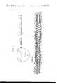
- FIG. 1is a side view of a pulse generator and pacing lead assembly which are constructed in accordance with the teachings of the present invention.
- FIG. 2is an enlarged sectional view of a multipolar electrode tip assembly which is mounted at the distal end of the pacing lead assembly shown in FIG. 1;
- FIG. 3is an enlarged sectional view of the multipolar insert connector at the proximal end of the pacing lead assembly shown in FIG. 1 received in a socket in a body portion of the pulse generator shown in FIG. 1.
- FIG. 4is a perspective view of a conductive resilient garter spring.
- FIG. 5is a fragmentary sectional view of a connector assembly utilizing the garter spring shown in FIG. 4.
- FIG. 6is a perspective view of a toroid made of woven metal wire.
- FIG. 7is a fragmentary sectional view of a connector assembly showing the use of the woven metal wire toroid shown in FIG. 6.
- FIG. 1there is illustrated therein a pulse generator and pacing lead assembly 10 which includes a multiconductor pacing lead 12 having at its distal end a multipolar electrode assembly 14 and a multipolar insert connector 16 at the proximal end thereof which is received within a socket 18 (FIG. 3) formed in a body portion 19 (FIG. 3) in a pulse generator 20.
- a multiconductor pacing lead 12having at its distal end a multipolar electrode assembly 14 and a multipolar insert connector 16 at the proximal end thereof which is received within a socket 18 (FIG. 3) formed in a body portion 19 (FIG. 3) in a pulse generator 20.
- the multiconductor pacing lead 12includes three conductors or wires 21, 22 and 23 which are wound in a single coil.
- the coiled conductors 21, 22 and 23are surrounded by an insulating sheath 26 which can be made of silicone, polyurethane, or other insulating material, but preferably is formed of PARYLENE "C” manufactured by Union Carbide Corporation.
- the distal end of the pacing lead 12extends within an electrode body 28 made of an insulating material and which forms part of the multipolar electrode assembly 14.
- a first electrode 31which can be referred to as a tip electrode 31.
- a second sleeve electrode 32spaced from the tip electrode 31 is a second sleeve electrode 32 and a third sleeve electrode 33 is spaced from the second sleeve electrode 32.
- the sleeve electrode 32is received in an annular slot 36 formed in the body 28 so that outer facing surface 38 of the sleeve electrode 32 is flush with outer cylindrical surface 40 of the insulating body 28.
- the second sleeve electrode 33is an annular slot 42 in the insulating body 28 so that outer surface 44 thereof is flush with the cylindrical surface 40 of the insulating body 28.
- each of the conductors or wires 21-23has an insulating coating thereon so that it is insulated from the adjacent conductor.
- the first conductor 21extends all the way to the first tip electrode 31 and an end portion 51 of the first conductor 21 extends through an opening 52 in the sheath 26.
- This end portion 51is stripped of insulation and extends from the opening 52 in the sheath 26 through a slot (not shown) in the sheath 26 to an annular cavity 54 defined between an inner cylindrical surface 55 formed within the electrode 31 and outer surface 56 of a plug 58 which extends from the inner end of the sheath 26 around a ring 60 and into the cylindrical cavity 55.
- the electrode 31is crimped at several points to retain the first conductor 21 between the outer surface 56 of the plug 58 and the inner cylindrical surface 55 of electrode 31 thereby to ensure a good electrical connection therewith.
- an end portion 62 of the second conductor or wire 22is stripped of insulation so as to be a bare wire and extends through an opening 63 in the sheath 26 through a passageway in the sheath 26 to an annular passageway 64 where the bare conductor end portion 62 is coiled.
- the annular passageway 64is defined between a thin layer (not shown) of electrode body 28 or the outer surface of the sheath 26 and the inner surface of the sleeve electrode 32.
- the width or thickness of the annular passageway 64is such that the bare wire end portion 62 is urged against the inner surface of the sleeve electrode 32 thereby to ensure a good electrical contact therewith.
- the third conductor 23has a bare end portion 73 which extends through an opening 74 in the sheath 26 and through a slot in the sheath 26 to an annular passageway 76 between a thin layer of the electrode body 28 or the outer surface of the sheath 26 and the inner surface of the third sleeve electrode 33.
- the dimension or width of the annular passageway 76is such that the bare conductor end portion 73 wound in a coil in the annular passageway 76 is urged against the inner surface of the sleeve electrode 33.
- the insulating body 28 which surrounds the distal end of the pacing lead 12has been defined as one piece construction but is shown in FIG. 2 as being of three piece construction, namely of three elements 81, 82 and 83.
- the multipolar electrode assembly 14, and in this particular instance, a three polar assembly 14,enables a physician to select any one of the three electrode 31, 32 or 33 for pacing the endocardium and for using any one of the electrodes 31, 32 and 33 for relaying information about selected tissue back to the pulse generator 20.
- FIG. 3is illustrated the position of the insert connector 16 at the proximal end of the multiconductor pacing lead 12 received in the socket 18 in the body portion 19 of the pulse generator 20.
- the sidewall of the socket 18is adapted to receive resilient flanges 101, 102 and 103 which extend from and are integral with an insulating body portion 104 of the insert connector 16.
- the flanges 101, 102 and 103will be flexed as shown for sealing the insert connector 16.
- the insulator body 104 and the flanges 101, 102 and 103 extending therefromare made from an elastomeric insulating material such as silicone.
- the sealing arrangement shown in FIG. 3is of the type shown in U.S. Pat. 4,259,962.
- the insulator body 104has a central passageway 106 therein which is sized to receive the proximal end of the multiconductor pacing lead 12.
- the end 108 of the insulator body 104 of the insert connector 16has a central passageway 110 therethrough which extends into the insulator body 104 and through a cylindrical protrusion 112 about which the proximal end 116 of the sheath 26 is received.
- This passageway 110permits a stylet to be inserted through the passgeway 110 and the insulator body 104 into the coiled conductors 21, 22 and 23 within the sheath 26 of the multiconductor pacing lead 12.
- the insulator body 104has been described above as being of unitary construction, it is preferably, and as shown in FIG. 3, made of insulating body segments which include the end segment 108, two identical intermediate segments 118 and 120 and an outer end segment 122.
- the end segment 108has an outer angular flange 124 extending inwardly and axially of the insert connector 16 and is spaced radially outwardly from the cylindrical protrusion 112.
- the intermediate segment 18has a similar annular flange 126 which extends toward the annular flange 124 so as to define an annular space, open in the middle, between the outer surface of the sheath 26 and the annular flanges 124 and 126.
- Received within this annular spaceis a spool-shaped metal band or ring 128 which has an annular slot 130 therein.
- the spool-shaped metal band 128has a radial slot 132 therein which receives the bare end 134 of the conductor 23 which bare end 134 extends from the insulated conductor 23 through an opening 136 in the sheath 26.
- a resilient ring 140 of conductive materialReceived within the slot 130 in the spool-shaped metal band 128 is a resilient ring 140 of conductive material which is adapted to electrically contact the slot 130 on its inwardly facing side and to electrically contact a metal ring 142 embedded in the body 19 and having an inwardly facing surface flush with the surface of the socket 18.
- the conductive ring 140is preferably made of a conductive resilient material such as silicon rubber. Also, as shown in FIG. 3, the ring 140 has a diameter which is greater than the space between the outer surface of the spool-shaped metal band 128 and the metal ring 142 embedded in the body 19 and having an inner surface flush with the surface of the socket 18 so that the ring 140 will be squeezed when the insert connector 16 is inserted into the socket 18. This is brought out in FIG. 3 by the showing of the normal unsqueezed position of the ring in phantom in FIG. 3.
- the conductive ring 140can also be made of other materials.
- itcould be a so-called garter spring which is a coiled spring in which two ends are brought together and welded so as to form a toroid envelope which can be squeezed when the insert connector 16 is inserted into the socket 18.
- garter springis a coiled spring in which two ends are brought together and welded so as to form a toroid envelope which can be squeezed when the insert connector 16 is inserted into the socket 18.
- Such a coiled springis shown in FIGS. 4 and 5 and will be described in greater detail hereinafter in connection with the description of FIGS. 4 and 5.
- conductive ringwould be a ring made of woven metal.
- a flat sheet of woven metalcould be rolled into a roll and then the roll formed into a toroid with the ends welded together, thereby to form a resilient ring 140.
- a toroid of woven metalis shown in FIGS. 6 and 7 and will be described in greater detail hereinafter in connection with the description of FIGS. 6 and 7.
- the insulator segment 118in addition to having the radially extending annular flange 103 and the axially extending annular flange 126 has a reduced-in-diameter portion 144 for facilitating flexing of the flange 103 when the insert connector 16 is inserted into the socket 18. Further, the segment 118 has another axially extending annular flange 146 as shown.
- the insulator segment 120is identical to the insulator segment 118 and in addition to having a radially extending flange 102, it has a reduced-in-diameter portion 148 and annular flanges 150 and 152.
- the insulator segment 120is positioned on the sheath 26 such that the annular flanges 150 and 146 form with the outer surface of the sheath 26 an annular space, open in the middle, for receiving a conductive resilient ring 154 which makes contact with a metal ring 156 embedded in the side wall of the socket 18 in the body portion 19 and the exposed surface of a spool-shaped metal band 158 received in the annular space.
- a bare end 162 of conductor 22extends through an opening 163 in the sheath 26 and is received in a slot 164 in the spool-shaped metal band 158 for making electrical contact therewith. In this way as in the previous electrical connection described above, electrical contact is effected between the end 162 of the conductor 22 through the metal band 158 and resilient conductive ring 154 to metal ring 156.
- the insulator segment 122is similar in construction to insulator segments 118 an 120 by having an axially extending annular flange 170 at one end thereof, the radially extending flange 101 and a reduced-in-diameter section 172.
- the outer end of segment 122is a solid body 174, as shown, which is received about the multiconductor pacing lead 12.
- the opposed ends of the insulator segments 120 and 122form an annular space for receiving a spool-shaped metal band 176 which has a conductive ring 178 extending thereabout and adapted to make electrical contact with a metal ring 180 embedded in the side wall of the socket 18 as shown. Also, a bare end 181 of conductor 21 extends through the sheath 26 where it is rigidly fixed into a slot in the spool-shaped metal band 176 to ensure a good electrical contact therewith.
- radially extending flanges 101, 102 and 103can be sized and configured to sealingly fit against the side wall of the socket 18.
- three electrical connector assemblies, 201, 203 and 204are created for facilitating good electrical connection between the ends 134, 162 and 181 of the conductors 23, 22 and 21 to the pulse generator circuitry (not shown) within the pulse generator 20.
- FIG. 4is shown a coiled endless garter spring 210 which may be inserted into each of the asemblies 201, 202, and 203 in place of the resilient conductive rings 140, 154 and 178.
- FIG. 5Such a construction is shown in FIG. 5 where the resilient garter spring 210 is shown between a spool shaped metal band 212 on the insert connector 16 and a metal band 214 embedded in the body 19.
- FIG. 6is shown a resilient toroid 220 which is made from a piece of woven metal wire which is first rolled into a tube and then coiled into a toroid and fixed at the mating ends thereof to form the toroid 220 shown in FIG. 6.
- This toroid 220can then be used in place of the resilient conductive rings 140, 154 and 178 in the connector assemblies 201, 202 and 203.
- FIG. 7the toroid 220 is shown between a spool shaped metal band 222 mounted on the connector 16 and a metal band 224 embedded in the body 19.
Landscapes
- Health & Medical Sciences (AREA)
- Engineering & Computer Science (AREA)
- Biomedical Technology (AREA)
- Nuclear Medicine, Radiotherapy & Molecular Imaging (AREA)
- Radiology & Medical Imaging (AREA)
- Life Sciences & Earth Sciences (AREA)
- Animal Behavior & Ethology (AREA)
- General Health & Medical Sciences (AREA)
- Public Health (AREA)
- Veterinary Medicine (AREA)
- Electrotherapy Devices (AREA)
Abstract
Description
Claims (9)
Priority Applications (1)
| Application Number | Priority Date | Filing Date | Title |
|---|---|---|---|
| US06/399,062US4469104A (en) | 1982-07-16 | 1982-07-16 | Multipolar connector for pacing lead |
Applications Claiming Priority (1)
| Application Number | Priority Date | Filing Date | Title |
|---|---|---|---|
| US06/399,062US4469104A (en) | 1982-07-16 | 1982-07-16 | Multipolar connector for pacing lead |
Publications (1)
| Publication Number | Publication Date |
|---|---|
| US4469104Atrue US4469104A (en) | 1984-09-04 |
Family
ID=23577969
Family Applications (1)
| Application Number | Title | Priority Date | Filing Date |
|---|---|---|---|
| US06/399,062Expired - LifetimeUS4469104A (en) | 1982-07-16 | 1982-07-16 | Multipolar connector for pacing lead |
Country Status (1)
| Country | Link |
|---|---|
| US (1) | US4469104A (en) |
Cited By (87)
| Publication number | Priority date | Publication date | Assignee | Title |
|---|---|---|---|---|
| EP0192082A3 (en)* | 1985-02-14 | 1987-06-03 | Medtronic, Inc. | Lead connector |
| US4712557A (en)* | 1986-04-28 | 1987-12-15 | Cordis Leads, Inc. | A pacer including a multiple connector assembly with removable wedge and method of use |
| US4802481A (en)* | 1984-07-19 | 1989-02-07 | Cordis Leads, Inc. | Apparatus for controlling pacing of a heart in response to changes in stroke volume |
| EP0319844A1 (en)* | 1987-12-04 | 1989-06-14 | Ad-Tech Medical Instrument Corporation | Electrical connectors for brain-contact devices |
| US4922607A (en)* | 1988-05-25 | 1990-05-08 | Medtronic, Inc. | Method of fabrication an in-line, multipolar electrical connector |
| EP0339877A3 (en)* | 1988-04-22 | 1990-05-30 | Medtronic, Inc. | In-line pacemaker connector system |
| US4938822A (en)* | 1983-10-17 | 1990-07-03 | Peers Trevarton C A | Method for making assembly of pacing lead electrode to coiled conductor |
| US4951687A (en)* | 1989-01-31 | 1990-08-28 | Medtronic, Inc. | Medical electrical lead connector |
| US4966564A (en)* | 1988-09-09 | 1990-10-30 | Telectronics, N.V. | Electrical connector between electrode leads and pacemaker terminal |
| US4971057A (en)* | 1989-05-03 | 1990-11-20 | Dr. Eckhard Alt | Electrical connecting means for establishing mechanical and electrical connections between an implantable medical device and a lead system |
| US5007435A (en)* | 1988-05-25 | 1991-04-16 | Medtronic, Inc. | Connector for multiconductor pacing leads |
| US5012807A (en)* | 1990-05-03 | 1991-05-07 | Siemens-Pacesetter, Inc. | Multi-part molded pacemaker connector and method of making same |
| EP0343402A3 (en)* | 1988-05-25 | 1991-06-05 | Medtronic, Inc. | Connector pin assembly and method of fabrication. |
| US5070605A (en)* | 1988-04-22 | 1991-12-10 | Medtronic, Inc. | Method for making an in-line pacemaker connector system |
| US5076270A (en)* | 1990-05-03 | 1991-12-31 | Siemens-Pacesetter, Inc. | Apparatus and method for making electrical connections in an implantable pacemaker |
| US5257622A (en)* | 1991-09-19 | 1993-11-02 | Medtronic, Inc. | Locking connector for implantable device |
| US5304219A (en)* | 1991-06-14 | 1994-04-19 | Siemens Pacesetter, Inc. | Multipolar in-line proximal connector assembly for an implantable stimulation device |
| US5314451A (en)* | 1993-01-15 | 1994-05-24 | Medtronic, Inc. | Replaceable battery for implantable medical device |
| US5330525A (en)* | 1993-04-29 | 1994-07-19 | Medtronic, Inc. | Epicardial lead having dual rotatable anchors |
| US5383913A (en)* | 1993-04-21 | 1995-01-24 | Schiff; Steven M. | Bidirectional lead connector for left or right sided implantation of pacemakers and/or other implantable electrophysiologic devices and a method for using the same |
| US5397343A (en)* | 1993-12-09 | 1995-03-14 | Medtronic, Inc. | Medical electrical lead having counter fixation anchoring system |
| US5545207A (en)* | 1994-08-24 | 1996-08-13 | Medtronic, Inc. | Medical electrical lead having stable fixation system |
| US5674272A (en)* | 1995-06-05 | 1997-10-07 | Ventritex, Inc. | Crush resistant implantable lead |
| WO1998048896A1 (en) | 1997-04-25 | 1998-11-05 | Medtronic, Inc. | Medical lead connector system |
| US6029089A (en)* | 1998-07-10 | 2000-02-22 | Pacesetter, Inc. | Lead retention and sealing system |
| US6039685A (en)* | 1998-09-14 | 2000-03-21 | St. Croix Medical, Inc. | Ventable connector with seals |
| US6366820B1 (en) | 2000-03-01 | 2002-04-02 | Pacesetter, Inc. | Interconnection technique between a cable conductor and an electrode of an implantable medical device |
| US20020055765A1 (en)* | 1999-04-26 | 2002-05-09 | Black Damon Ray | Implantable lead and method of manufacture |
| US6463334B1 (en) | 1998-11-02 | 2002-10-08 | Cardiac Pacemakers, Inc. | Extendable and retractable lead |
| US6501990B1 (en) | 1999-12-23 | 2002-12-31 | Cardiac Pacemakers, Inc. | Extendable and retractable lead having a snap-fit terminal connector |
| US6501994B1 (en) | 1997-12-24 | 2002-12-31 | Cardiac Pacemakers, Inc. | High impedance electrode tip |
| US6505082B1 (en) | 1998-07-22 | 2003-01-07 | Cardiac Pacemakers, Inc. | Single pass lead system |
| US20030050680A1 (en)* | 2001-09-07 | 2003-03-13 | Gibson Scott R. | Electronic lead for a medical implant device, method of making same, and method and apparatus for inserting same |
| EP1147783A3 (en)* | 2000-04-19 | 2003-04-02 | Ad-Tech Medical Instrument Corporation | Electrical connector for multi-contact medical electrodes |
| US20030074031A1 (en)* | 2000-12-15 | 2003-04-17 | Ley Gregory R. | Micro terminal connector |
| US20030085684A1 (en)* | 2001-11-07 | 2003-05-08 | Quallion Llc | Implantable medical power module |
| US20030163171A1 (en)* | 2002-02-28 | 2003-08-28 | Kast John E. | In-line lead header for an implantable medical device |
| US20030171783A1 (en)* | 2002-03-08 | 2003-09-11 | Quallion Llc | Battery terminal sealing and supporting device and method |
| US6643550B2 (en) | 2000-12-15 | 2003-11-04 | Cardiac Pacemakers, Inc. | Multi-polar connector |
| US6807439B2 (en) | 2001-04-03 | 2004-10-19 | Medtronic, Inc. | System and method for detecting dislodgement of an implantable medical device |
| US20040267328A1 (en)* | 2003-06-24 | 2004-12-30 | Medtronic, Inc. | Electrode selection system for medical electrical leads |
| US20050043771A1 (en)* | 2003-08-21 | 2005-02-24 | Medtronic, Inc. | Multi-polar electrical medical lead connector system |
| US20050043770A1 (en)* | 2003-08-21 | 2005-02-24 | Medtronic, Inc. | Multi-polar electrical medical lead connector system |
| US20060030204A1 (en)* | 2004-08-09 | 2006-02-09 | Advanced Neuromodulation Systems, Inc. | System and method for providing strain relief for medical device leads |
| US20060047322A1 (en)* | 2004-08-26 | 2006-03-02 | Jacques Naviaux | Electrical conductive path for a medical electronics device |
| US20070100386A1 (en)* | 2005-10-31 | 2007-05-03 | Medtronic, Inc. | Axial lead connector for implantable medical device |
| US7245973B2 (en) | 2003-12-23 | 2007-07-17 | Cardiac Pacemakers, Inc. | His bundle mapping, pacing, and injection lead |
| US20070250143A1 (en)* | 2006-04-19 | 2007-10-25 | Sommer John L | Multi-conductor ribbon coiled medical device lead |
| US20080009192A1 (en)* | 2006-03-23 | 2008-01-10 | Medtronic, Inc. | Medical electrical lead connection systems and methods |
| DE102006053729A1 (en)* | 2006-11-15 | 2008-05-21 | Biotronik Crm Patent Ag | Contact assembly, contact assembly, implantable device and electrode lead |
| US20100240253A1 (en)* | 2007-10-03 | 2010-09-23 | Medltronic Inc. | Connector Assemblies for Implantable Medical Electrical Systems |
| US20100240240A1 (en)* | 2009-03-19 | 2010-09-23 | Ochoa Francisco | Flexible connector for implantable electrical stimulation lead |
| US20100304592A1 (en)* | 2007-10-02 | 2010-12-02 | Kast John E | Connector Assemblies and Contacts for Implantable Medical Electrical Systems |
| US20120245657A1 (en)* | 2011-03-25 | 2012-09-27 | Pacesetter, Inc. | Lead retention system for a pulse generator |
| US8285376B2 (en) | 2004-12-20 | 2012-10-09 | Cardiac Pacemakers, Inc. | Ventricular pacing |
| US8290586B2 (en) | 2004-12-20 | 2012-10-16 | Cardiac Pacemakers, Inc. | Methods, devices and systems for single-chamber pacing using a dual-chamber pacing device |
| US8326423B2 (en) | 2004-12-20 | 2012-12-04 | Cardiac Pacemakers, Inc. | Devices and methods for steering electrical stimulation in cardiac rhythm management |
| US8423139B2 (en) | 2004-12-20 | 2013-04-16 | Cardiac Pacemakers, Inc. | Methods, devices and systems for cardiac rhythm management using an electrode arrangement |
| WO2013101683A1 (en)* | 2011-12-28 | 2013-07-04 | Cardiac Pacemakers, Inc. | Toroidal compressible element including a switchback pattern |
| US8494636B2 (en) | 2011-03-29 | 2013-07-23 | Greatbatch Ltd. | Feed-through connector assembly for implantable pulse generator and method of use |
| US8538521B2 (en) | 2004-12-20 | 2013-09-17 | Cardiac Pacemakers, Inc. | Systems, devices and methods for monitoring efficiency of pacing |
| US8543203B2 (en) | 2004-12-20 | 2013-09-24 | Cardiac Pacemakers, Inc. | Endocardial pacing devices and methods useful for resynchronization and defibrillation |
| US8565880B2 (en) | 2010-04-27 | 2013-10-22 | Cardiac Pacemakers, Inc. | His-bundle capture verification and monitoring |
| US8666494B2 (en) | 2010-04-29 | 2014-03-04 | Donatelle Plastics, Inc. | Header for implantable pulse generator and method of making same |
| US8688234B2 (en) | 2008-12-19 | 2014-04-01 | Cardiac Pacemakers, Inc. | Devices, methods, and systems including cardiac pacing |
| US8738141B2 (en) | 2011-04-07 | 2014-05-27 | Greatbatch, Ltd. | Contact assembly for implantable pulse generator and method of use |
| US8761887B2 (en) | 2010-04-29 | 2014-06-24 | Donatelle Plastics, Inc. | Header for implantable pulse generator and method of making same |
| US8880169B2 (en) | 2004-12-20 | 2014-11-04 | Cardiac Pacemakers, Inc. | Endocardial pacing relating to conduction abnormalities |
| US20140378008A1 (en)* | 2013-06-25 | 2014-12-25 | Bal Seal Engineering, Inc. | Electrical contacts with electrically conductive springs |
| US9138586B2 (en) | 2012-01-27 | 2015-09-22 | Greatbatch Ltd. | Contact block using spherical electrical contacts for electrically contacting implantable leads |
| JP2015531307A (en)* | 2012-10-17 | 2015-11-02 | カーディアック ペースメイカーズ, インコーポレイテッド | Terminal ring configuration to prevent improper electrical contact between IS4 compliant lead connector and DF4 compliant connector port |
| US20150364861A1 (en)* | 2014-06-17 | 2015-12-17 | Minnetronix, Inc. | Implantable connection mechanisms for continuous high power delivery |
| US9403022B2 (en) | 2010-01-29 | 2016-08-02 | Medtronic, Inc. | Header assembly for implantable medical device |
| US9855413B2 (en) | 2010-04-29 | 2018-01-02 | Donatelle Plastics, Inc. | Header for implantable pulse generator and method of making same |
| US9855376B2 (en) | 2014-07-25 | 2018-01-02 | Minnetronix, Inc. | Power scaling |
| US9931513B2 (en) | 2011-03-29 | 2018-04-03 | Nuvectra Corporation | Feed-through connector assembly for implantable pulse generator and method of use |
| WO2018208992A1 (en)* | 2017-05-09 | 2018-11-15 | Nalu Medical, Inc. | Stimulation apparatus |
| US10149933B2 (en) | 2014-07-25 | 2018-12-11 | Minnetronix, Inc. | Coil parameters and control |
| US10193395B2 (en) | 2015-04-14 | 2019-01-29 | Minnetronix, Inc. | Repeater resonator |
| US10342908B2 (en) | 2015-01-14 | 2019-07-09 | Minnetronix, Inc. | Distributed transformer |
| US10406267B2 (en) | 2015-01-16 | 2019-09-10 | Minnetronix, Inc. | Data communication in a transcutaneous energy transfer system |
| US11116987B2 (en)* | 2019-04-17 | 2021-09-14 | Biotronik Se & Co. Kg | Electrical contact component |
| US11766561B2 (en) | 2016-07-18 | 2023-09-26 | Nalu Medical, Inc. | Methods and systems for treating pelvic disorders and pain conditions |
| US11826569B2 (en) | 2017-02-24 | 2023-11-28 | Nalu Medical, Inc. | Apparatus with sequentially implanted stimulators |
| US11938327B2 (en) | 2016-03-21 | 2024-03-26 | Nalu Medical, Inc. | Devices and methods for positioning external devices in relation to implanted devices |
| US12186563B2 (en) | 2014-06-21 | 2025-01-07 | Nalu Medical, Inc. | Method and apparatus for neuromodulation treatments of pain and other conditions |
| US12390650B2 (en) | 2016-12-30 | 2025-08-19 | Nalu Medical, Inc. | Stimulation apparatus |
Citations (7)
| Publication number | Priority date | Publication date | Assignee | Title |
|---|---|---|---|---|
| US3924639A (en)* | 1974-07-17 | 1975-12-09 | Cordis Corp | Cardiac pacer lead system for interim pacing during pacer changeover |
| US4012103A (en)* | 1975-09-03 | 1977-03-15 | Medtronic, Inc. | Antishock, insulated connector |
| US4033355A (en)* | 1975-11-28 | 1977-07-05 | Cardiac Pacemakers, Inc. | Electrode lead assembly for implantable devices and method of preparing same |
| US4259962A (en)* | 1979-08-24 | 1981-04-07 | Cordis Corporation | Sealing system for cardiac pacer lead connector |
| US4262982A (en)* | 1977-03-10 | 1981-04-21 | Needle Industries Ltd. | Electrical socket useful for connecting an electrode catheter to a cardiac pacemaker casing |
| DE3023191A1 (en)* | 1980-06-18 | 1981-12-24 | Biotronik Meß- und Therapiegeräte GmbH & Co Ingenieurbüro Berlin, 1000 Berlin | Implanted heart pacemaker electrode - has carrier wire wound with one or more fine wire layers providing conductive surface |
| US4379462A (en)* | 1980-10-29 | 1983-04-12 | Neuromed, Inc. | Multi-electrode catheter assembly for spinal cord stimulation |
- 1982
- 1982-07-16USUS06/399,062patent/US4469104A/ennot_activeExpired - Lifetime
Patent Citations (7)
| Publication number | Priority date | Publication date | Assignee | Title |
|---|---|---|---|---|
| US3924639A (en)* | 1974-07-17 | 1975-12-09 | Cordis Corp | Cardiac pacer lead system for interim pacing during pacer changeover |
| US4012103A (en)* | 1975-09-03 | 1977-03-15 | Medtronic, Inc. | Antishock, insulated connector |
| US4033355A (en)* | 1975-11-28 | 1977-07-05 | Cardiac Pacemakers, Inc. | Electrode lead assembly for implantable devices and method of preparing same |
| US4262982A (en)* | 1977-03-10 | 1981-04-21 | Needle Industries Ltd. | Electrical socket useful for connecting an electrode catheter to a cardiac pacemaker casing |
| US4259962A (en)* | 1979-08-24 | 1981-04-07 | Cordis Corporation | Sealing system for cardiac pacer lead connector |
| DE3023191A1 (en)* | 1980-06-18 | 1981-12-24 | Biotronik Meß- und Therapiegeräte GmbH & Co Ingenieurbüro Berlin, 1000 Berlin | Implanted heart pacemaker electrode - has carrier wire wound with one or more fine wire layers providing conductive surface |
| US4379462A (en)* | 1980-10-29 | 1983-04-12 | Neuromed, Inc. | Multi-electrode catheter assembly for spinal cord stimulation |
Cited By (165)
| Publication number | Priority date | Publication date | Assignee | Title |
|---|---|---|---|---|
| US4938822A (en)* | 1983-10-17 | 1990-07-03 | Peers Trevarton C A | Method for making assembly of pacing lead electrode to coiled conductor |
| US4802481A (en)* | 1984-07-19 | 1989-02-07 | Cordis Leads, Inc. | Apparatus for controlling pacing of a heart in response to changes in stroke volume |
| EP0192082A3 (en)* | 1985-02-14 | 1987-06-03 | Medtronic, Inc. | Lead connector |
| US4712557A (en)* | 1986-04-28 | 1987-12-15 | Cordis Leads, Inc. | A pacer including a multiple connector assembly with removable wedge and method of use |
| EP0319844A1 (en)* | 1987-12-04 | 1989-06-14 | Ad-Tech Medical Instrument Corporation | Electrical connectors for brain-contact devices |
| US5070605A (en)* | 1988-04-22 | 1991-12-10 | Medtronic, Inc. | Method for making an in-line pacemaker connector system |
| EP0339877A3 (en)* | 1988-04-22 | 1990-05-30 | Medtronic, Inc. | In-line pacemaker connector system |
| EP0343402A3 (en)* | 1988-05-25 | 1991-06-05 | Medtronic, Inc. | Connector pin assembly and method of fabrication. |
| US5007435A (en)* | 1988-05-25 | 1991-04-16 | Medtronic, Inc. | Connector for multiconductor pacing leads |
| US4922607A (en)* | 1988-05-25 | 1990-05-08 | Medtronic, Inc. | Method of fabrication an in-line, multipolar electrical connector |
| US4966564A (en)* | 1988-09-09 | 1990-10-30 | Telectronics, N.V. | Electrical connector between electrode leads and pacemaker terminal |
| US4951687A (en)* | 1989-01-31 | 1990-08-28 | Medtronic, Inc. | Medical electrical lead connector |
| US4971057A (en)* | 1989-05-03 | 1990-11-20 | Dr. Eckhard Alt | Electrical connecting means for establishing mechanical and electrical connections between an implantable medical device and a lead system |
| US5012807A (en)* | 1990-05-03 | 1991-05-07 | Siemens-Pacesetter, Inc. | Multi-part molded pacemaker connector and method of making same |
| US5076270A (en)* | 1990-05-03 | 1991-12-31 | Siemens-Pacesetter, Inc. | Apparatus and method for making electrical connections in an implantable pacemaker |
| EP0484483A4 (en)* | 1990-05-03 | 1992-09-30 | Siemens Elema Ab | Multi-part molded pacemaker connector, manufacturing method, and pacemaker header assembly |
| US5304219A (en)* | 1991-06-14 | 1994-04-19 | Siemens Pacesetter, Inc. | Multipolar in-line proximal connector assembly for an implantable stimulation device |
| US5257622A (en)* | 1991-09-19 | 1993-11-02 | Medtronic, Inc. | Locking connector for implantable device |
| US5314451A (en)* | 1993-01-15 | 1994-05-24 | Medtronic, Inc. | Replaceable battery for implantable medical device |
| US5383913A (en)* | 1993-04-21 | 1995-01-24 | Schiff; Steven M. | Bidirectional lead connector for left or right sided implantation of pacemakers and/or other implantable electrophysiologic devices and a method for using the same |
| US5330525A (en)* | 1993-04-29 | 1994-07-19 | Medtronic, Inc. | Epicardial lead having dual rotatable anchors |
| US5397343A (en)* | 1993-12-09 | 1995-03-14 | Medtronic, Inc. | Medical electrical lead having counter fixation anchoring system |
| US5545207A (en)* | 1994-08-24 | 1996-08-13 | Medtronic, Inc. | Medical electrical lead having stable fixation system |
| US5674272A (en)* | 1995-06-05 | 1997-10-07 | Ventritex, Inc. | Crush resistant implantable lead |
| WO1998048896A1 (en) | 1997-04-25 | 1998-11-05 | Medtronic, Inc. | Medical lead connector system |
| US5843141A (en)* | 1997-04-25 | 1998-12-01 | Medronic, Inc. | Medical lead connector system |
| US6501994B1 (en) | 1997-12-24 | 2002-12-31 | Cardiac Pacemakers, Inc. | High impedance electrode tip |
| US6029089A (en)* | 1998-07-10 | 2000-02-22 | Pacesetter, Inc. | Lead retention and sealing system |
| US8285398B2 (en) | 1998-07-22 | 2012-10-09 | Cardiac Pacemakers, Inc. | Lead with terminal connector assembly |
| US8209035B2 (en) | 1998-07-22 | 2012-06-26 | Cardiac Pacemakers, Inc. | Extendable and retractable lead having a snap-fit terminal connector |
| US7774934B2 (en)* | 1998-07-22 | 2010-08-17 | Cardiac Pacemakers, Inc. | Method for making a terminal connector |
| US6505082B1 (en) | 1998-07-22 | 2003-01-07 | Cardiac Pacemakers, Inc. | Single pass lead system |
| US7392095B2 (en) | 1998-07-22 | 2008-06-24 | Cardiac Pacemakers, Inc. | Extendable and retractable lead having a snap-fit terminal connector |
| US6915169B2 (en) | 1998-07-22 | 2005-07-05 | Cardiac Pacemakers, Inc. | Extendable and retractable lead having a snap-fit terminal connector |
| US6983185B2 (en) | 1998-07-22 | 2006-01-03 | Cardiac Pacemakers, Inc. | Lead with terminal connector assembly |
| US6039685A (en)* | 1998-09-14 | 2000-03-21 | St. Croix Medical, Inc. | Ventable connector with seals |
| US6463334B1 (en) | 1998-11-02 | 2002-10-08 | Cardiac Pacemakers, Inc. | Extendable and retractable lead |
| US6981314B2 (en) | 1999-04-26 | 2006-01-03 | Advanced Neuromodulation Systems, Inc. | Method of forming a lead |
| US20050138791A1 (en)* | 1999-04-26 | 2005-06-30 | Black Damon R. | Method of forming a lead |
| US20020055765A1 (en)* | 1999-04-26 | 2002-05-09 | Black Damon Ray | Implantable lead and method of manufacture |
| US8316537B2 (en) | 1999-04-26 | 2012-11-27 | Advanced Neuromodulation Systems, Inc. | Method of forming a lead |
| US8671566B2 (en) | 1999-04-26 | 2014-03-18 | Advanced Neuromodulation Systems, Inc. | Method of forming a lead |
| US7047627B2 (en) | 1999-04-26 | 2006-05-23 | Advanced Neuromodulation Systems, Inc. | Method for fabricating an implantable apparatus for delivering electrical stimulation from a pulse generator |
| US20100077606A1 (en)* | 1999-04-26 | 2010-04-01 | Damon Ray Black | Method of forming a lead |
| US20050246005A1 (en)* | 1999-04-26 | 2005-11-03 | Black Damon R | Method for fabricating an implantable apparatus for delivering electrical stimulation from a pulse generator |
| US20050192655A1 (en)* | 1999-04-26 | 2005-09-01 | Black Damon R. | Method of forming a lead |
| US20050138792A1 (en)* | 1999-04-26 | 2005-06-30 | Black Damon R. | Method of forming a lead |
| US6501990B1 (en) | 1999-12-23 | 2002-12-31 | Cardiac Pacemakers, Inc. | Extendable and retractable lead having a snap-fit terminal connector |
| US6366820B1 (en) | 2000-03-01 | 2002-04-02 | Pacesetter, Inc. | Interconnection technique between a cable conductor and an electrode of an implantable medical device |
| EP1147783A3 (en)* | 2000-04-19 | 2003-04-02 | Ad-Tech Medical Instrument Corporation | Electrical connector for multi-contact medical electrodes |
| US20030074031A1 (en)* | 2000-12-15 | 2003-04-17 | Ley Gregory R. | Micro terminal connector |
| US6895277B2 (en) | 2000-12-15 | 2005-05-17 | Cardiac Pacemakers, Inc. | Multi-polar connector |
| US20040093052A1 (en)* | 2000-12-15 | 2004-05-13 | Cardiac Pacemaker, Inc. | Multi-polar connector |
| US7234977B2 (en) | 2000-12-15 | 2007-06-26 | Cardiac Pacemakers, Inc. | Multi-polar connector |
| US20050202703A1 (en)* | 2000-12-15 | 2005-09-15 | Cardiac Pacemakers, Inc. | Multi-polar connector |
| US20050234522A1 (en)* | 2000-12-15 | 2005-10-20 | Cardiac Pacemakers, Inc. | Terminal connector assembly for a medical device and method therefor |
| US6912423B2 (en) | 2000-12-15 | 2005-06-28 | Cardiac Pacemakers, Inc. | Terminal connector assembly for a medical device and method therefor |
| US6643550B2 (en) | 2000-12-15 | 2003-11-04 | Cardiac Pacemakers, Inc. | Multi-polar connector |
| US6807439B2 (en) | 2001-04-03 | 2004-10-19 | Medtronic, Inc. | System and method for detecting dislodgement of an implantable medical device |
| US20030050680A1 (en)* | 2001-09-07 | 2003-03-13 | Gibson Scott R. | Electronic lead for a medical implant device, method of making same, and method and apparatus for inserting same |
| US6671554B2 (en)* | 2001-09-07 | 2003-12-30 | Medtronic Minimed, Inc. | Electronic lead for a medical implant device, method of making same, and method and apparatus for inserting same |
| US7486048B2 (en) | 2001-11-07 | 2009-02-03 | Quallion Llc | Implantable power module for powering a medical device |
| US7009362B2 (en) | 2001-11-07 | 2006-03-07 | Quallion Llc | Standalone implantable medical power module |
| US20050021100A1 (en)* | 2001-11-07 | 2005-01-27 | Quallion Llc | Implantable medical power module |
| US20030085684A1 (en)* | 2001-11-07 | 2003-05-08 | Quallion Llc | Implantable medical power module |
| US6894456B2 (en) | 2001-11-07 | 2005-05-17 | Quallion Llc | Implantable medical power module |
| US20030163171A1 (en)* | 2002-02-28 | 2003-08-28 | Kast John E. | In-line lead header for an implantable medical device |
| US6895276B2 (en) | 2002-02-28 | 2005-05-17 | Medtronic, Inc. | In-line lead header for an implantable medical device |
| US7003356B2 (en) | 2002-03-08 | 2006-02-21 | Quallion Llc | Battery terminal sealing and supporting device and method |
| US20030171783A1 (en)* | 2002-03-08 | 2003-09-11 | Quallion Llc | Battery terminal sealing and supporting device and method |
| US20040267328A1 (en)* | 2003-06-24 | 2004-12-30 | Medtronic, Inc. | Electrode selection system for medical electrical leads |
| US20050043770A1 (en)* | 2003-08-21 | 2005-02-24 | Medtronic, Inc. | Multi-polar electrical medical lead connector system |
| US8437856B2 (en) | 2003-08-21 | 2013-05-07 | Medtronic, Inc. | Multi-polar electrical medical lead connector system |
| US8065008B2 (en)* | 2003-08-21 | 2011-11-22 | Medtronic, Inc. | Multi-polar electrical medical lead connector system |
| US8019420B2 (en)* | 2003-08-21 | 2011-09-13 | Medtronic, Inc. | Medical lead connector systems with adapters |
| US20050043771A1 (en)* | 2003-08-21 | 2005-02-24 | Medtronic, Inc. | Multi-polar electrical medical lead connector system |
| US7245973B2 (en) | 2003-12-23 | 2007-07-17 | Cardiac Pacemakers, Inc. | His bundle mapping, pacing, and injection lead |
| US8078287B2 (en) | 2003-12-23 | 2011-12-13 | Cardiac Pacemakers, Inc. | His bundle mapping, pacing, and injection lead |
| EP1625875A1 (en)* | 2004-08-09 | 2006-02-15 | Advanced Neuromodulation Systems, Inc. | System and method for providing strain relief for medical device leads |
| US20060030204A1 (en)* | 2004-08-09 | 2006-02-09 | Advanced Neuromodulation Systems, Inc. | System and method for providing strain relief for medical device leads |
| US7195523B2 (en)* | 2004-08-26 | 2007-03-27 | Bal Seal Engineering Co., Inc. | Electrical conductive path for a medical electronics device |
| US20060047322A1 (en)* | 2004-08-26 | 2006-03-02 | Jacques Naviaux | Electrical conductive path for a medical electronics device |
| US8825159B2 (en) | 2004-12-20 | 2014-09-02 | Cardiac Pacemakers, Inc. | Devices and methods for steering electrical stimulation in cardiac rhythm management |
| US8838238B2 (en) | 2004-12-20 | 2014-09-16 | Cardiac Pacemakers, Inc. | Ventricular pacing |
| US9031648B2 (en) | 2004-12-20 | 2015-05-12 | Cardiac Pacemakers, Inc. | Endocardial pacing devices and methods useful for resynchronization and defibrillation |
| US9008768B2 (en) | 2004-12-20 | 2015-04-14 | Cardiac Pacemakers, Inc. | Methods, devices and systems for cardiac rhythm management using an electrode arrangement |
| US8934969B2 (en) | 2004-12-20 | 2015-01-13 | Cardiac Pacemakers, Inc. | Systems, devices and methods for monitoring efficiency of pacing |
| US8903489B2 (en) | 2004-12-20 | 2014-12-02 | Cardiac Pacemakers, Inc. | Methods, devices and systems for single-chamber pacing using a dual-chamber pacing device |
| US8880169B2 (en) | 2004-12-20 | 2014-11-04 | Cardiac Pacemakers, Inc. | Endocardial pacing relating to conduction abnormalities |
| US8812106B2 (en) | 2004-12-20 | 2014-08-19 | Cardiac Pacemakers, Inc. | Apparatus for treating the physiological electric conduction of the heart |
| US8543203B2 (en) | 2004-12-20 | 2013-09-24 | Cardiac Pacemakers, Inc. | Endocardial pacing devices and methods useful for resynchronization and defibrillation |
| US8538521B2 (en) | 2004-12-20 | 2013-09-17 | Cardiac Pacemakers, Inc. | Systems, devices and methods for monitoring efficiency of pacing |
| US8437848B2 (en) | 2004-12-20 | 2013-05-07 | Cardiac Pacemakers, Inc. | Apparatus for treating the physiological electric conduction of the heart |
| US8428715B2 (en) | 2004-12-20 | 2013-04-23 | Cardiac Pacemakers, Inc. | Methods for treating the physiological electric conduction of the heart |
| US8423139B2 (en) | 2004-12-20 | 2013-04-16 | Cardiac Pacemakers, Inc. | Methods, devices and systems for cardiac rhythm management using an electrode arrangement |
| US8346358B2 (en) | 2004-12-20 | 2013-01-01 | Cardiac Pacemakers, Inc. | Pacemaker which reestablishes or keeps the physiological electric conduction of the heart and a method of application |
| US8326423B2 (en) | 2004-12-20 | 2012-12-04 | Cardiac Pacemakers, Inc. | Devices and methods for steering electrical stimulation in cardiac rhythm management |
| US8290586B2 (en) | 2004-12-20 | 2012-10-16 | Cardiac Pacemakers, Inc. | Methods, devices and systems for single-chamber pacing using a dual-chamber pacing device |
| US8285376B2 (en) | 2004-12-20 | 2012-10-09 | Cardiac Pacemakers, Inc. | Ventricular pacing |
| US8401649B2 (en) | 2005-10-31 | 2013-03-19 | Medtronic, Inc. | Axial lead connector for implantable medical device |
| US7590451B2 (en) | 2005-10-31 | 2009-09-15 | Medtronic, Inc. | Axial lead connector for implantable medical devices |
| US20070100386A1 (en)* | 2005-10-31 | 2007-05-03 | Medtronic, Inc. | Axial lead connector for implantable medical device |
| US20100035453A1 (en)* | 2005-10-31 | 2010-02-11 | Medtronic, Inc. | Axial lead connector for implantable medical device |
| US20080009192A1 (en)* | 2006-03-23 | 2008-01-10 | Medtronic, Inc. | Medical electrical lead connection systems and methods |
| US7402083B2 (en) | 2006-03-23 | 2008-07-22 | Medtronic, Inc. | Medical electrical lead connection systems and methods |
| US20080248696A1 (en)* | 2006-03-23 | 2008-10-09 | Medtronic, Inc. | Medical electrical lead connection systems and methods |
| US7553193B2 (en) | 2006-03-23 | 2009-06-30 | Medtronic, Inc. | Medical electrical lead connection systems and methods |
| US20090247018A1 (en)* | 2006-03-23 | 2009-10-01 | Medtronic, Inc. | Medical electrical lead connection systems and methods |
| US7798862B2 (en) | 2006-03-23 | 2010-09-21 | Medtronic, Inc. | Medical electrical lead connection systems and methods |
| US20070250143A1 (en)* | 2006-04-19 | 2007-10-25 | Sommer John L | Multi-conductor ribbon coiled medical device lead |
| DE102006053729A1 (en)* | 2006-11-15 | 2008-05-21 | Biotronik Crm Patent Ag | Contact assembly, contact assembly, implantable device and electrode lead |
| EP1923967A3 (en)* | 2006-11-15 | 2009-04-22 | BIOTRONIK CRM Patent AG | Contact arrangement, contact assembly, implantable device and electrode lead |
| US20090099620A1 (en)* | 2006-11-15 | 2009-04-16 | Rebentisch Ronald | Contact configuration, contact assembly, implantable apparatus and electrode line |
| US9112325B2 (en) | 2006-11-15 | 2015-08-18 | Biotronik Crm Patent Ag | Contact configuration, contact assembly, implantable apparatus and electrode line |
| US20100304592A1 (en)* | 2007-10-02 | 2010-12-02 | Kast John E | Connector Assemblies and Contacts for Implantable Medical Electrical Systems |
| US8123567B2 (en) | 2007-10-02 | 2012-02-28 | Medtronic, Inc. | Connector assemblies and contacts for implantable medical electrical systems |
| US8206180B1 (en) | 2007-10-02 | 2012-06-26 | Medtronic Inc. | Connector assemblies and contacts for implantable medical electrical systems |
| US8412330B2 (en) | 2007-10-03 | 2013-04-02 | Medtronic, Inc. | Connector assemblies for implantable medical electrical systems |
| US20100240253A1 (en)* | 2007-10-03 | 2010-09-23 | Medltronic Inc. | Connector Assemblies for Implantable Medical Electrical Systems |
| US8688234B2 (en) | 2008-12-19 | 2014-04-01 | Cardiac Pacemakers, Inc. | Devices, methods, and systems including cardiac pacing |
| US20100240240A1 (en)* | 2009-03-19 | 2010-09-23 | Ochoa Francisco | Flexible connector for implantable electrical stimulation lead |
| US8167640B2 (en) | 2009-03-19 | 2012-05-01 | Bioness Inc. | Flexible connector for implantable electrical stimulation lead |
| WO2010107648A1 (en)* | 2009-03-19 | 2010-09-23 | Bioness Inc. | Flexible connector for implantable electrical stimulation lead |
| US9403022B2 (en) | 2010-01-29 | 2016-08-02 | Medtronic, Inc. | Header assembly for implantable medical device |
| US8565880B2 (en) | 2010-04-27 | 2013-10-22 | Cardiac Pacemakers, Inc. | His-bundle capture verification and monitoring |
| US9855413B2 (en) | 2010-04-29 | 2018-01-02 | Donatelle Plastics, Inc. | Header for implantable pulse generator and method of making same |
| US8761887B2 (en) | 2010-04-29 | 2014-06-24 | Donatelle Plastics, Inc. | Header for implantable pulse generator and method of making same |
| US8666494B2 (en) | 2010-04-29 | 2014-03-04 | Donatelle Plastics, Inc. | Header for implantable pulse generator and method of making same |
| US9089686B2 (en) | 2010-04-29 | 2015-07-28 | Donatelle Plastics, Inc. | Header for implantable pulse generator and method of making same |
| US20120245657A1 (en)* | 2011-03-25 | 2012-09-27 | Pacesetter, Inc. | Lead retention system for a pulse generator |
| US8972012B2 (en)* | 2011-03-25 | 2015-03-03 | Pacesetter, Inc. | Lead retention system for a pulse generator |
| US9931513B2 (en) | 2011-03-29 | 2018-04-03 | Nuvectra Corporation | Feed-through connector assembly for implantable pulse generator and method of use |
| US8494636B2 (en) | 2011-03-29 | 2013-07-23 | Greatbatch Ltd. | Feed-through connector assembly for implantable pulse generator and method of use |
| US9492666B2 (en) | 2011-04-07 | 2016-11-15 | Nuvectra Corporation | Contact assembly for implantable pulse generator and method of use |
| US8738141B2 (en) | 2011-04-07 | 2014-05-27 | Greatbatch, Ltd. | Contact assembly for implantable pulse generator and method of use |
| AU2012362623B2 (en)* | 2011-12-28 | 2015-09-10 | Cardiac Pacemakers, Inc. | Toroidal compressible element including a switchback pattern |
| US9308380B2 (en)* | 2011-12-28 | 2016-04-12 | Cardiac Pacemakers, Inc. | Toroidal compressible element including a switchback pattern |
| US10226635B2 (en) | 2011-12-28 | 2019-03-12 | Cardiac Pacemakers, Inc. | Toroidal compressible element including a switchback pattern |
| WO2013101683A1 (en)* | 2011-12-28 | 2013-07-04 | Cardiac Pacemakers, Inc. | Toroidal compressible element including a switchback pattern |
| US20130172949A1 (en)* | 2011-12-28 | 2013-07-04 | Mark Stevenson | Toroidal compressible element including a switchback pattern |
| US9138586B2 (en) | 2012-01-27 | 2015-09-22 | Greatbatch Ltd. | Contact block using spherical electrical contacts for electrically contacting implantable leads |
| JP2015531307A (en)* | 2012-10-17 | 2015-11-02 | カーディアック ペースメイカーズ, インコーポレイテッド | Terminal ring configuration to prevent improper electrical contact between IS4 compliant lead connector and DF4 compliant connector port |
| US10263368B2 (en)* | 2013-06-25 | 2019-04-16 | Bal Seal Engineering, Inc. | Electrical contacts with electrically conductive springs |
| US20140378008A1 (en)* | 2013-06-25 | 2014-12-25 | Bal Seal Engineering, Inc. | Electrical contacts with electrically conductive springs |
| US10847935B2 (en) | 2013-06-25 | 2020-11-24 | Bal Seal Engineering, Llc | Electrical contacts with electrically conductive springs |
| US20150364861A1 (en)* | 2014-06-17 | 2015-12-17 | Minnetronix, Inc. | Implantable connection mechanisms for continuous high power delivery |
| US12186563B2 (en) | 2014-06-21 | 2025-01-07 | Nalu Medical, Inc. | Method and apparatus for neuromodulation treatments of pain and other conditions |
| US10898628B2 (en) | 2014-07-25 | 2021-01-26 | Minnetronix, Inc. | Coil parameters and control |
| US10149933B2 (en) | 2014-07-25 | 2018-12-11 | Minnetronix, Inc. | Coil parameters and control |
| US9855376B2 (en) | 2014-07-25 | 2018-01-02 | Minnetronix, Inc. | Power scaling |
| US10376625B2 (en) | 2014-07-25 | 2019-08-13 | Minnetronix, Inc. | Power scaling |
| US11207516B2 (en) | 2015-01-14 | 2021-12-28 | Minnetronix, Inc. | Distributed transformer |
| US10342908B2 (en) | 2015-01-14 | 2019-07-09 | Minnetronix, Inc. | Distributed transformer |
| US10406267B2 (en) | 2015-01-16 | 2019-09-10 | Minnetronix, Inc. | Data communication in a transcutaneous energy transfer system |
| US11235141B2 (en) | 2015-01-16 | 2022-02-01 | Minnetronix, Inc. | Data communication in a transcutaneous energy transfer system |
| US11894695B2 (en) | 2015-04-14 | 2024-02-06 | Minnetronix, Inc. | Repeater resonator |
| US10193395B2 (en) | 2015-04-14 | 2019-01-29 | Minnetronix, Inc. | Repeater resonator |
| US11938327B2 (en) | 2016-03-21 | 2024-03-26 | Nalu Medical, Inc. | Devices and methods for positioning external devices in relation to implanted devices |
| US11766561B2 (en) | 2016-07-18 | 2023-09-26 | Nalu Medical, Inc. | Methods and systems for treating pelvic disorders and pain conditions |
| US12390650B2 (en) | 2016-12-30 | 2025-08-19 | Nalu Medical, Inc. | Stimulation apparatus |
| US11826569B2 (en) | 2017-02-24 | 2023-11-28 | Nalu Medical, Inc. | Apparatus with sequentially implanted stimulators |
| US11097096B2 (en) | 2017-05-09 | 2021-08-24 | Nalu Medical, Inc. | Stimulation apparatus |
| WO2018208992A1 (en)* | 2017-05-09 | 2018-11-15 | Nalu Medical, Inc. | Stimulation apparatus |
| US12201829B2 (en) | 2017-05-09 | 2025-01-21 | Nalu Medical, Inc. | Stimulation apparatus |
| US11116987B2 (en)* | 2019-04-17 | 2021-09-14 | Biotronik Se & Co. Kg | Electrical contact component |
Similar Documents
| Publication | Publication Date | Title |
|---|---|---|
| US4469104A (en) | Multipolar connector for pacing lead | |
| US4458695A (en) | Multipolar electrode assembly for pacing lead | |
| US4437474A (en) | Method for making multiconductor coil and the coil made thereby | |
| US4590950A (en) | Electrical connection | |
| US4493329A (en) | Implantable electrode having different stiffening and curvature maintaining characteristics along its length | |
| US6289250B1 (en) | Implantable electrode lead | |
| US5458629A (en) | Implantable lead ring electrode and method of making | |
| US5545201A (en) | Bipolar active fixation lead for sensing and pacing the heart | |
| US4592372A (en) | Pacing/sensing electrode sleeve and method of forming same | |
| US4236525A (en) | Multiple function lead assembly | |
| US5796044A (en) | Coiled wire conductor insulation for biomedical lead | |
| US4479500A (en) | Pacing lead with A-V distance adapter | |
| US4577643A (en) | Movable multi-contact electromechanical connection | |
| EP1427477B1 (en) | Medical lead connector | |
| CA1082317A (en) | Body implantable lead with stiffening stylet | |
| US8019420B2 (en) | Medical lead connector systems with adapters | |
| US6925334B1 (en) | Implantable medical lead having multiple, jointly insulated electrical conductors | |
| US4744370A (en) | Lead assembly with selectable electrode connection | |
| US6456888B1 (en) | Geometry for coupling and electrode to a conductor | |
| USRE31990E (en) | Multiple function lead assembly and method for inserting assembly into an implantable tissue stimulator | |
| US5824030A (en) | Lead with inter-electrode spacing adjustment | |
| US4355646A (en) | Transvenous defibrillating lead | |
| US4328812A (en) | Ring electrode for pacing lead | |
| US6253111B1 (en) | Multi-conductor lead | |
| US5571157A (en) | Endocardial lead with reduced diameter tip portion and method for making such lead |
Legal Events
| Date | Code | Title | Description |
|---|---|---|---|
| AS | Assignment | Owner name:CORDIS CORPORATION 1055 WEST FLAGLER ST MIAMI,FLA. Free format text:ASSIGNMENT OF ASSIGNORS INTEREST.;ASSIGNOR:PEERS-TREVARTON, CHARLES A.;REEL/FRAME:004030/0619 Effective date:19820629 | |
| STCF | Information on status: patent grant | Free format text:PATENTED CASE | |
| AS | Assignment | Owner name:SOUTHEAST BANK, N.A., MIDLAD BANK PLC (SINGAPORE B Free format text:SECURITY INTEREST;ASSIGNOR:CORDIS LEADS, INC., A CORP. OF DE;REEL/FRAME:004747/0320 Effective date:19870612 | |
| AS | Assignment | Owner name:SOUTHEAST BANK, N.A., MIDLAND BANK PLC (SINGAPORE Free format text:SECURITY INTEREST;ASSIGNOR:CORDIS HEADS, INC.;REEL/FRAME:004734/0550 Effective date:19870630 | |
| AS | Assignment | Owner name:CORDIS LEADS, INC., 10555 WEST FLAGLER STREET, MIA Free format text:ASSIGNMENT OF ASSIGNORS INTEREST.;ASSIGNOR:CORDIS CORPORATION, A CORP. OF FLORIDA;REEL/FRAME:004747/0313 Effective date:19870430 Owner name:CORDIS LEADS, INC., FLORIDA Free format text:ASSIGNMENT OF ASSIGNORS INTEREST;ASSIGNOR:CORDIS CORPORATION, A CORP. OF FLORIDA;REEL/FRAME:004747/0313 Effective date:19870430 | |
| FEPP | Fee payment procedure | Free format text:PAYOR NUMBER ASSIGNED (ORIGINAL EVENT CODE: ASPN); ENTITY STATUS OF PATENT OWNER: LARGE ENTITY | |
| FPAY | Fee payment | Year of fee payment:4 | |
| AS | Assignment | Owner name:SOUTHEAST BANK, N.A. Free format text:SECURITY INTEREST;ASSIGNOR:CORDIS LEADS, INC., A DE CORP.;REEL/FRAME:004896/0205 Effective date:19880602 | |
| AS | Assignment | Owner name:SOUTHEAST BANK, N.A., AS SECURITY AGENT Free format text:SECURITY INTEREST;ASSIGNOR:CORDIS LEADS, INC., A CORP. OF DE;REEL/FRAME:004896/0372 Effective date:19880610 | |
| AS | Assignment | Owner name:CORDIS LEADS, INC., 10555 W. FLAGLER STR., MIAMI, Free format text:RELEASED BY SECURED PARTY;ASSIGNOR:SOUTHEAST BANK, N.A., MIDLAND BANK PLC AND CREDIT LYONNAIS;REEL/FRAME:004996/0829 Effective date:19880615 Owner name:TPL-CORDIS, INC., A DE CORP., FLORIDA Free format text:NUNC PRO TUNC ASSIGNMENT;ASSIGNOR:CORDIS LEADS, INC.;REEL/FRAME:005003/0158 Effective date:19881130 Owner name:TELECTRONICS, INC., A DE CORP., CONNECTICUT Free format text:NUNC PRO TUNC ASSIGNMENT;ASSIGNOR:TPL-CORDIS, INC.;REEL/FRAME:005003/0166 Effective date:19881130 | |
| AS | Assignment | Owner name:TELECTRONICS, U.S.A., INC., CONNECTICUT Free format text:RELEASED BY SECURED PARTY;ASSIGNOR:SOUTHEAST BANK N.A.;REEL/FRAME:005181/0530 Effective date:19890831 | |
| FPAY | Fee payment | Year of fee payment:8 | |
| AS | Assignment | Owner name:TELECTRONICS PACING SYSTEMS, INC., COLORADO Free format text:ASSIGNORS HEREBY CONFIRMS THE ENTIRE INTEREST IN SAID INVENTIONS TO ASSIGNEE ELECUTED ON SEPT. 16, 1988;ASSIGNORS:TELECTRONICS PTY. LTD.;MEDICAL TELECTRONICS HOLDING & FINANCE CO.;TELECTRONIC NV;AND OTHERS;REEL/FRAME:006172/0028 Effective date:19920622 | |
| FPAY | Fee payment | Year of fee payment:12 | |
| AS | Assignment | Owner name:TELECTRONICS PACING SYSTEMS, INC., COLORADO Free format text:CORRECTIVE ASSIGNMENT TO CORRECT ASSIGNEE'S STATE OF INCORPORATION. AN ASSIGNMENT WAS PREVIOUSLY RECORDED AT REEL 6172, FRAME 0028;ASSIGNORS:TELECTRONICS PTY. LTD., AN AUSTRALIAN COMPANY;MEDICAL TELECTRONICS HOLDING & FINANCE CO. (BV), A DUTCH COMPANY;TELECTRONICS NV, A COMPANY OF THE NETHERLANDS ANTILLES;AND OTHERS;REEL/FRAME:008321/0072 Effective date:19961101 | |
| AS | Assignment | Owner name:PACESETTER, INC., CALIFORNIA Free format text:ASSIGNMENT OF ASSIGNORS INTEREST;ASSIGNOR:TELECTRONICS PACING SYSTEMS;REEL/FRAME:008454/0461 Effective date:19961129 |