US4468327A - Effluent treatment - Google Patents
Effluent treatmentDownload PDFInfo
- Publication number
- US4468327A US4468327AUS06/471,907US47190783AUS4468327AUS 4468327 AUS4468327 AUS 4468327AUS 47190783 AUS47190783 AUS 47190783AUS 4468327 AUS4468327 AUS 4468327A
- Authority
- US
- United States
- Prior art keywords
- tank
- effluent
- inlet
- sludge
- decanting
- Prior art date
- Legal status (The legal status is an assumption and is not a legal conclusion. Google has not performed a legal analysis and makes no representation as to the accuracy of the status listed.)
- Expired - Fee Related
Links
- 238000005273aerationMethods0.000claimsabstractdescription11
- 239000010802sludgeSubstances0.000claimsdescription20
- 238000000034methodMethods0.000claimsdescription16
- 239000007787solidSubstances0.000claimsdescription15
- 239000007788liquidSubstances0.000claimsdescription9
- QVGXLLKOCUKJST-UHFFFAOYSA-Natomic oxygenChemical compound[O]QVGXLLKOCUKJST-UHFFFAOYSA-N0.000claimsdescription7
- 229910052760oxygenInorganic materials0.000claimsdescription7
- 239000001301oxygenSubstances0.000claimsdescription7
- 230000004071biological effectEffects0.000claimsdescription3
- 230000035939shockEffects0.000abstractdescription4
- 125000004122cyclic groupChemical group0.000abstractdescription2
- 238000009792diffusion processMethods0.000abstractdescription2
- 239000002699waste materialSubstances0.000description5
- IJGRMHOSHXDMSA-UHFFFAOYSA-NAtomic nitrogenChemical compoundN#NIJGRMHOSHXDMSA-UHFFFAOYSA-N0.000description4
- 239000002351wastewaterSubstances0.000description4
- OAICVXFJPJFONN-UHFFFAOYSA-NPhosphorusChemical compound[P]OAICVXFJPJFONN-UHFFFAOYSA-N0.000description2
- 235000013305foodNutrition0.000description2
- 229910052757nitrogenInorganic materials0.000description2
- 229910052698phosphorusInorganic materials0.000description2
- 239000011574phosphorusSubstances0.000description2
- 238000005086pumpingMethods0.000description2
- 238000005276aeratorMethods0.000description1
- 150000001720carbohydratesChemical class0.000description1
- 238000005352clarificationMethods0.000description1
- 239000004567concreteSubstances0.000description1
- 238000010276constructionMethods0.000description1
- 235000013365dairy productNutrition0.000description1
- 230000001627detrimental effectEffects0.000description1
- 235000013399edible fruitsNutrition0.000description1
- 230000001747exhibiting effectEffects0.000description1
- 238000009293extended aerationMethods0.000description1
- 230000004907fluxEffects0.000description1
- 230000005484gravityEffects0.000description1
- 239000004519greaseSubstances0.000description1
- 230000002706hydrostatic effectEffects0.000description1
- 230000000977initiatory effectEffects0.000description1
- 239000003562lightweight materialSubstances0.000description1
- 239000000463materialSubstances0.000description1
- 244000005700microbiomeSpecies0.000description1
- MEFBJEMVZONFCJ-UHFFFAOYSA-NmolybdateChemical compound[O-][Mo]([O-])(=O)=OMEFBJEMVZONFCJ-UHFFFAOYSA-N0.000description1
- 235000015097nutrientsNutrition0.000description1
- 239000011150reinforced concreteSubstances0.000description1
- 238000000926separation methodMethods0.000description1
- 238000013517stratificationMethods0.000description1
- 235000013311vegetablesNutrition0.000description1
- XLYOFNOQVPJJNP-UHFFFAOYSA-NwaterSubstancesOXLYOFNOQVPJJNP-UHFFFAOYSA-N0.000description1
Images

Classifications
- C—CHEMISTRY; METALLURGY
- C02—TREATMENT OF WATER, WASTE WATER, SEWAGE, OR SLUDGE
- C02F—TREATMENT OF WATER, WASTE WATER, SEWAGE, OR SLUDGE
- C02F3/00—Biological treatment of water, waste water, or sewage
- C02F3/02—Aerobic processes
- C02F3/12—Activated sludge processes
- C02F3/1205—Particular type of activated sludge processes
- C02F3/121—Multistep treatment
- C—CHEMISTRY; METALLURGY
- C02—TREATMENT OF WATER, WASTE WATER, SEWAGE, OR SLUDGE
- C02F—TREATMENT OF WATER, WASTE WATER, SEWAGE, OR SLUDGE
- C02F3/00—Biological treatment of water, waste water, or sewage
- C02F3/02—Aerobic processes
- C02F3/12—Activated sludge processes
- C—CHEMISTRY; METALLURGY
- C02—TREATMENT OF WATER, WASTE WATER, SEWAGE, OR SLUDGE
- C02F—TREATMENT OF WATER, WASTE WATER, SEWAGE, OR SLUDGE
- C02F3/00—Biological treatment of water, waste water, or sewage
- C02F3/02—Aerobic processes
- C02F3/12—Activated sludge processes
- C02F3/1236—Particular type of activated sludge installations
- C02F3/1263—Sequencing batch reactors [SBR]
- C—CHEMISTRY; METALLURGY
- C02—TREATMENT OF WATER, WASTE WATER, SEWAGE, OR SLUDGE
- C02F—TREATMENT OF WATER, WASTE WATER, SEWAGE, OR SLUDGE
- C02F3/00—Biological treatment of water, waste water, or sewage
- C02F3/02—Aerobic processes
- C02F3/12—Activated sludge processes
- C02F3/1278—Provisions for mixing or aeration of the mixed liquor
- C02F3/1294—"Venturi" aeration means
- Y—GENERAL TAGGING OF NEW TECHNOLOGICAL DEVELOPMENTS; GENERAL TAGGING OF CROSS-SECTIONAL TECHNOLOGIES SPANNING OVER SEVERAL SECTIONS OF THE IPC; TECHNICAL SUBJECTS COVERED BY FORMER USPC CROSS-REFERENCE ART COLLECTIONS [XRACs] AND DIGESTS
- Y02—TECHNOLOGIES OR APPLICATIONS FOR MITIGATION OR ADAPTATION AGAINST CLIMATE CHANGE
- Y02W—CLIMATE CHANGE MITIGATION TECHNOLOGIES RELATED TO WASTEWATER TREATMENT OR WASTE MANAGEMENT
- Y02W10/00—Technologies for wastewater treatment
- Y02W10/10—Biological treatment of water, waste water, or sewage
Definitions
- This inventionrelates to effluent treatment.
- the inventionconsists in a method of treating effluent comprising the steps of passing said effluent through an inlet into one end of a tank having a length between 3.5 and 6 times the width thereof, diffusing air into said effluent for a predetermined period of time, allowing the contents of said tank to settle for a predetermined time, and decanting liquid from the surface thereof or adjacent the opposite end of said tank from said inlet.
- the inventionconsists in an effluent treatment system comprising a tank having a length between 3.5 and 6 times the width thereof, an inlet adjacent one end of said tank, air diffusers arranged to be submerged within said tank in use, air supply means arranged to supply air to said diffusers, and decanting means arranged to decant liquid from the surface of effluent held within said tank at or adjacent the opposite end of said tank from said inlet.
- the tankincorporates a baffle wall across the width thereof adjacent said inlet, said wall having apertures adjacent the lower edge thereof for passing said effluent therethrough.
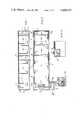
- FIG. 1is a cross-sectional elevation of the tank of an effluent treatment system according to the invention
- FIG. 2is a plan view of the effluent treatment system according to the invention.
- FIG. 3is a cross-sectional elevation along the line A--A of FIG. 2,
- FIG. 4is a cross-sectional elevation along the line B--B of FIG. 2,
- FIG. 5is a cross-sectional elevation along the line C--C of FIG. 2,
- FIG. 6is a plan view of an alternate tank configuration for use with an effuent treatment system according to the invention.
- FIG. 7is a cross-sectional elevation along the line D--D of FIG. 6.
- an effluent treatment systemis constructed as follows:
- a tank 1is provided which may for example be constructed from reinforced concrete or from any other suitable material and which may be sunk in the ground or supported upon the surface of the ground.
- the tankhas a length equal to 4 times the width of the tank although it has been found that the system works effectively with tank lengths anywhere between 3.5 to 6 times the width of the tank, although it is preferred to keep the ratio between 4 and 5 to 1.
- the tankis provided with an inlet 2 at one end 3 of the tank end and adjacent the inlet a transverse baffle wall 4 is provided which may for example be a concrete block wall.
- the baffle wallextends the full height of the tank and is provided with openings 5 (FIG. 5) at or adjacent to the lower edge of the baffle wall to allow effluent passing into the tank through the inlet 2 to pass through the openings 5 and into the main body 6 of the tank.
- the tankis provided with a plurality of air diffusion nozzles 7 arranged to be submerged within the tank in use and preferably located adjacent the side walls close to the bottom of the tank.
- the nozzlesare connected to dropper pipes 8 and thence to manifold pipes 9 located on the upper edge of the walls of the tank, connected to an air supply pipe 10.
- An air supply apparatus 11in the form of motor-driven compressors or blowers is provided, arranged to pump air through pipes 9 and 10 to dropper pipes 8 and hence to the diffuser nozzles 7.
- the diffuser nozzlesmay take any convenient form such as aerators, jet nozzles or bell type nozzles or any other type of diffuser.
- a decanter 12is provided, arranged to decant liquid from the surface of effluent held within the tank adjacent the opposite end 13 of the tank from the inlet 2.
- the decantermay take any suitable and known form but is preferably a floating weir type decanter connected by downcomer pipes 14 to an outlet pipe 15 which passes through the tank wall to suitable pumping or draining connections.
- the decantermay be supported from the pipe 15 by way of the downcomer pipes 14 so that the height of the decanter may be adjusted by rotating the pipe 15 by way of a crank apparatus 16.
- the tank for the effluent treatment systemhas been described as a single tank having a length 4 times the width thereof, it will be appreciated that the same configuration may be achieved in a square type tank or tank of other configuration by placing baffles within the tank to break up the tank area into volumes each having a length approximately 4 times the width thereof.
- FIG. 6Such a construction is shown in FIG. 6 in which an approximately square tank 17 is divided by way of a full length centre baffle 18 and shorter baffles 19 into 4 areas 20 each having a length 4 times the width thereof. Decanters 21 are provided in a similar manner to that shown in FIGS. 1, 2 and 4. The tank is also provided with a baffle wall 22 located adjacent the inlet 23 to the tank.
- FIGS. 6 and 7has the particular advantage that it is more economical to construct, as the tank side wall length for a square tank per volume contained within the tank, is less than that needed for a single rectangular tank of the type shown in FIG. 2.
- the baffle walls 18 and 19need only be constructed of a light weight material as they do not need to withstand any hydrostatic pressure operating on one side of the wall only.
- the tankhas further economy in that a single decanter 21 may be used to decant liquid from two adjacent areas 20.
- a tank as describedis adequate to handle may effluent treatment demands but in some situations intermittent high concentrations of effluent resulting in high food to microbe ratios (F/M) have to be treated.
- the tankmay be provided with a series of additional baffles such as those shown at 30 and 31.
- the baffle 30extends across the tank flush with the tank floor to a height equivalent to a minimum of the designated bottom water level.
- the third baffle 31is similar to the first baffle wall 4 and may have apertures 32 adjacent the lower edge of the tank flow or may terminate short of the tank floor.
- the chambers formed by the baffleseach have at least one diffuser nozzle 7 therein.
- the systemIn use the system is designed to contain a process known as extended aeration and to operate this process intermittently 4 times a day. Each period is divided into 6 hours and is a total cycle unto itself.
- the tankis filled with effluent through the inlet 2 and air is then pumped from the pumping apparatus 11 through the pipes 10, 9 and 8 to the diffuser nozzles 7.
- a period of settling or clarificationfollows during which time the sludge in the tank is allowed to settle to the bottom, and the decanter 12 is then actuated for a predetermined period to draw off the clear liquid from the top of the tank.
- the cyclemay be manually or automatically controlled from a control panel and switchboard 24 which contains starting equipment for the air blowers that provide the air for aeration, and also the equipment to actuate the linkage 16 which may be hydraulically actuated to bring the decanter 12 into operation.
- a sludge pump(not shown) may also be provided arranged to pump settled sludge from the bottom of the tank when desired. The sludge pump may also be controlled by the control panel 24 and may be functionally independent of each cycle of operation.
- the feature of providing a tank having a length 4 times the width thereofis important to prevent short circuiting of the effluent which otherwise has a momentum and is caused to rise due to temperature differences, to be entrained in the decanter.
- the length of the tankat least 3.5 times the width, and preferably 4 or 5 times, so that short circuiting is avoided clear liquid is able to be decanted at the decanter 12.
- the basic feature of the inventionis its ability to continuously accept inflows of wastewaters, without any prior load balancing, using a single vessel (or subcompartmental single vessel). Treatment and load balancing occur simultaneously. To dimensions described above are important to the hydraulic functioning of the invention and prevent direct short circuiting.
- the transverse bafflesare also a special feature of the invention and are incorporated to serve as energy dissipators, to prevent short circuiting caused by stratification (due to specific gravity differences of effluent wastewaters and liquid contained within the vessel) and to physically contain or stop grease as floating balls which are then biodegraded.
- the total sequence of aeration, settlement and decant in the cyclic operationis not necessarily specific, although total periods of 4 hours, 6 hours, and 12 hours are in common use. Any suitable combination of sequences may be used.
- a further picture of the baffle or baffles as used in this inventionrelates to the generation of an activated sludge which exhibits good settlement properties. In vessels without baffles, similar good settlement is achieved by proper selection of the non aeration sequence.
- an organic loading parameterwhich is defined in practice as the F to M ratio.
- the F/M ratiois described as the unit weight of BOD applied in 24 hours divided by the unit weight of activated sludge (called mixed liquor suspended solids) held in the vessel.
- the unit weight in metric unitsis kilograms. This invention reaches to an F/M ratio of up to 0.4 calculated as stated.
- concentration of activated sludgeis expressed as concentration of mixed liquor suspended solids (MLSS) or mixed liquor volatile suspended solids (MLVSS) (usually expressed as milligrams per liter) and may be in practice from 300 to 15,000 milligrams per liter.
- a feature of the invention where transverse baffles are usedis its ability to accept "shock organic loads" without biological upset to the process--a biological sludge of good settleability is maintained.
- wastewatersare caused to be received in such a way that upon initiation of the aeration sequence an immediate F/M ratio (calculated on the MLSS solids content of the first baffled compartment) of up to 5 units in the inlet zone results.
- This zone and the high F/M ratiois instrumental to the efficacy of this invention in that it serves to generate the growth of micro-organisms which do not result in a sludge having poor settlement characteristics.
- mixed liquor from this zoneproceeds to the next zone or subsequent multiple zones.
- a further feature of this inventionis the biological activity (measured as oxygen uptake rate with units of milligrams of oxygen per gram of mixed liquor suspended solids per hour) in the various zones or sections of the vessel. Values as high as 300, at temperature up to 35° C. occur in the first inlet zone. Total biological solids in these systems is also described in terms of flux and in this invention relates to a solid content of up to 15 pounds of biological solids per square foot of vessel floor area.
- the subcompartment volumes in any particular systemare not easily specified as their volume is determined by the strength of wastewaters being treated.
- the volume ratiomay be 1:10 to 1:3.
- the F/M ratio on which the total system is sizedIn typical systems this may be in the ratio of 1:1:2 to 1:1:10.
Landscapes
- Life Sciences & Earth Sciences (AREA)
- Biodiversity & Conservation Biology (AREA)
- Microbiology (AREA)
- Hydrology & Water Resources (AREA)
- Engineering & Computer Science (AREA)
- Environmental & Geological Engineering (AREA)
- Water Supply & Treatment (AREA)
- Chemical & Material Sciences (AREA)
- Organic Chemistry (AREA)
- Activated Sludge Processes (AREA)
Abstract
Description
Claims (10)
Applications Claiming Priority (4)
| Application Number | Priority Date | Filing Date | Title |
|---|---|---|---|
| AUPD6206 | 1978-10-03 | ||
| AUPD620678 | 1978-10-03 | ||
| AUPD7708 | 1979-02-16 | ||
| AUPD770879 | 1979-02-16 |
Related Parent Applications (1)
| Application Number | Title | Priority Date | Filing Date |
|---|---|---|---|
| US06323592Continuation | 1981-11-20 |
Publications (1)
| Publication Number | Publication Date |
|---|---|
| US4468327Atrue US4468327A (en) | 1984-08-28 |
Family
ID=25642254
Family Applications (1)
| Application Number | Title | Priority Date | Filing Date |
|---|---|---|---|
| US06/471,907Expired - Fee RelatedUS4468327A (en) | 1978-10-03 | 1983-03-09 | Effluent treatment |
Country Status (2)
| Country | Link |
|---|---|
| US (1) | US4468327A (en) |
| AU (1) | AU5138379A (en) |
Cited By (15)
| Publication number | Priority date | Publication date | Assignee | Title |
|---|---|---|---|---|
| US4596658A (en)* | 1984-01-30 | 1986-06-24 | Mandt Mikkel G | Sequencing batch reactor decanter systems |
| US4663044A (en)* | 1985-09-13 | 1987-05-05 | Transfield, Incorporated | Biological treatment of wastewater |
| US4810386A (en)* | 1988-01-04 | 1989-03-07 | Zimpro/Passavant Inc. | Two-stage wastewater treatment |
| US4897196A (en)* | 1988-02-17 | 1990-01-30 | Zimpro/Passavant Inc. | Two-stage batch wastewater treatment |
| US4968008A (en)* | 1986-02-07 | 1990-11-06 | Envirotech Corporation | Bioleaching apparatus and system |
| US4974816A (en)* | 1986-02-07 | 1990-12-04 | Envirotech Corporation | Method and apparatus for biological processing of metal-containing ores |
| US5007620A (en)* | 1986-02-07 | 1991-04-16 | Envirotech Corporation | Apparatus for biological processing of metal-containing ores |
| US5057284A (en)* | 1986-02-07 | 1991-10-15 | Envirotech | Bioslurry reactor for treatment of slurries containing minerals, soils and sludges |
| US5316671A (en)* | 1993-01-21 | 1994-05-31 | Murphy D Thomas | Submersible aeration train and aeration apparatus for biological purification of sewage |
| US5352356A (en)* | 1991-09-03 | 1994-10-04 | Murphy D Thomas | Stovepipe decanter apparatus |
| US5374353A (en)* | 1993-01-21 | 1994-12-20 | Murphy; D. Thomas | Aeration train and aeration apparatus for biological purification of wastewater |
| US6303026B1 (en) | 1998-09-28 | 2001-10-16 | Glen D. Lindbo | Wastewater treatment tank with influent gates and pre-react zone with an outwardly flared lower portion |
| US6697740B2 (en) | 2002-02-19 | 2004-02-24 | William G. Smith | Method and system for real-time control of sampling instruments in a batch operation |
| EP1647530A1 (en)* | 2004-10-14 | 2006-04-19 | ITT Manufacturing Enterprises, Inc. | Energy-efficient biological treatment with membrane filtration |
| US11155482B2 (en)* | 2018-04-04 | 2021-10-26 | Somerset Environmental Solutions Inc. | Apparatus and method for aerating wastewater |
Citations (11)
| Publication number | Priority date | Publication date | Assignee | Title |
|---|---|---|---|---|
| US3133017A (en)* | 1959-09-24 | 1964-05-12 | Dorr Oliver Inc | Method and apparatus for activated sludge treatment |
| US3151063A (en)* | 1960-01-06 | 1964-09-29 | Denver Equip Co | Aerobic process for stabilization of sewage sludge |
| US3215276A (en)* | 1961-12-08 | 1965-11-02 | Rex Chainbelt Inc | Adjustable baffle grit chamber |
| US3460677A (en)* | 1968-10-22 | 1969-08-12 | Rolland L Fifer | Transportable sewage treating apparatus |
| US3470092A (en)* | 1967-05-08 | 1969-09-30 | Degremont Sa | System for the purification of waste waters |
| US3649531A (en)* | 1969-04-18 | 1972-03-14 | Nat Res Dev | Dewatering of digested sludge |
| US3732160A (en)* | 1968-08-21 | 1973-05-08 | Research Corp | Submerged filter-horizontal flow mode |
| US3809245A (en)* | 1972-01-31 | 1974-05-07 | S Kennedy | Sewage treatment apparatus |
| US3875056A (en)* | 1970-01-27 | 1975-04-01 | Stenberg Flygt Ab | Device for sewage treatment |
| US4081368A (en)* | 1975-09-24 | 1978-03-28 | Air Products & Chemicals, Inc. | Activated sludge system with staggered partition basin |
| US4179366A (en)* | 1974-11-18 | 1979-12-18 | Union Carbide Corporation | Method for the biological purification of effluent and the plant for carrying out the process |
- 1978
- 1978-10-03AUAU51383/79Apatent/AU5138379A/ennot_activeAbandoned
- 1983
- 1983-03-09USUS06/471,907patent/US4468327A/ennot_activeExpired - Fee Related
Patent Citations (11)
| Publication number | Priority date | Publication date | Assignee | Title |
|---|---|---|---|---|
| US3133017A (en)* | 1959-09-24 | 1964-05-12 | Dorr Oliver Inc | Method and apparatus for activated sludge treatment |
| US3151063A (en)* | 1960-01-06 | 1964-09-29 | Denver Equip Co | Aerobic process for stabilization of sewage sludge |
| US3215276A (en)* | 1961-12-08 | 1965-11-02 | Rex Chainbelt Inc | Adjustable baffle grit chamber |
| US3470092A (en)* | 1967-05-08 | 1969-09-30 | Degremont Sa | System for the purification of waste waters |
| US3732160A (en)* | 1968-08-21 | 1973-05-08 | Research Corp | Submerged filter-horizontal flow mode |
| US3460677A (en)* | 1968-10-22 | 1969-08-12 | Rolland L Fifer | Transportable sewage treating apparatus |
| US3649531A (en)* | 1969-04-18 | 1972-03-14 | Nat Res Dev | Dewatering of digested sludge |
| US3875056A (en)* | 1970-01-27 | 1975-04-01 | Stenberg Flygt Ab | Device for sewage treatment |
| US3809245A (en)* | 1972-01-31 | 1974-05-07 | S Kennedy | Sewage treatment apparatus |
| US4179366A (en)* | 1974-11-18 | 1979-12-18 | Union Carbide Corporation | Method for the biological purification of effluent and the plant for carrying out the process |
| US4081368A (en)* | 1975-09-24 | 1978-03-28 | Air Products & Chemicals, Inc. | Activated sludge system with staggered partition basin |
Cited By (21)
| Publication number | Priority date | Publication date | Assignee | Title |
|---|---|---|---|---|
| US4596658A (en)* | 1984-01-30 | 1986-06-24 | Mandt Mikkel G | Sequencing batch reactor decanter systems |
| US4663044A (en)* | 1985-09-13 | 1987-05-05 | Transfield, Incorporated | Biological treatment of wastewater |
| US4968008A (en)* | 1986-02-07 | 1990-11-06 | Envirotech Corporation | Bioleaching apparatus and system |
| US4974816A (en)* | 1986-02-07 | 1990-12-04 | Envirotech Corporation | Method and apparatus for biological processing of metal-containing ores |
| US5007620A (en)* | 1986-02-07 | 1991-04-16 | Envirotech Corporation | Apparatus for biological processing of metal-containing ores |
| US5057284A (en)* | 1986-02-07 | 1991-10-15 | Envirotech | Bioslurry reactor for treatment of slurries containing minerals, soils and sludges |
| US4810386A (en)* | 1988-01-04 | 1989-03-07 | Zimpro/Passavant Inc. | Two-stage wastewater treatment |
| US4897196A (en)* | 1988-02-17 | 1990-01-30 | Zimpro/Passavant Inc. | Two-stage batch wastewater treatment |
| US5384049A (en)* | 1991-09-03 | 1995-01-24 | Murphy; D. Thomas | Wastewater treatment process |
| US5352356A (en)* | 1991-09-03 | 1994-10-04 | Murphy D Thomas | Stovepipe decanter apparatus |
| US5374353A (en)* | 1993-01-21 | 1994-12-20 | Murphy; D. Thomas | Aeration train and aeration apparatus for biological purification of wastewater |
| US5316671A (en)* | 1993-01-21 | 1994-05-31 | Murphy D Thomas | Submersible aeration train and aeration apparatus for biological purification of sewage |
| US6303026B1 (en) | 1998-09-28 | 2001-10-16 | Glen D. Lindbo | Wastewater treatment tank with influent gates and pre-react zone with an outwardly flared lower portion |
| US6697740B2 (en) | 2002-02-19 | 2004-02-24 | William G. Smith | Method and system for real-time control of sampling instruments in a batch operation |
| EP1647530A1 (en)* | 2004-10-14 | 2006-04-19 | ITT Manufacturing Enterprises, Inc. | Energy-efficient biological treatment with membrane filtration |
| US20060081534A1 (en)* | 2004-10-14 | 2006-04-20 | Dimitriou Michael A | Energy-efficient biological treatment with membrane filtration |
| US20060213831A1 (en)* | 2004-10-14 | 2006-09-28 | Dimitriou Michael A | Energy-efficient biological treatment system with filtration membrane |
| US7118674B2 (en) | 2004-10-14 | 2006-10-10 | Itt Manufacturing Enterprises, Inc. | Energy-efficient biological treatment with membrane filtration |
| US7179370B2 (en) | 2004-10-14 | 2007-02-20 | Itt Manufacturing Enterprises, Inc. | Energy-efficient biological treatment system with filtration membrane |
| US7476322B2 (en) | 2004-10-14 | 2009-01-13 | Itt Manufacturing Enterprises, Inc. | Process and energy-efficient biological treatment system with filtration membrane |
| US11155482B2 (en)* | 2018-04-04 | 2021-10-26 | Somerset Environmental Solutions Inc. | Apparatus and method for aerating wastewater |
Also Published As
| Publication number | Publication date |
|---|---|
| AU5138379A (en) | 1980-04-17 |
Similar Documents
| Publication | Publication Date | Title |
|---|---|---|
| US4468327A (en) | Effluent treatment | |
| US5186821A (en) | Wastewater treatment process with cooperating velocity equalization, aeration and decanting means | |
| US5316671A (en) | Submersible aeration train and aeration apparatus for biological purification of sewage | |
| US5374353A (en) | Aeration train and aeration apparatus for biological purification of wastewater | |
| US6086765A (en) | Multi-stage facultative wastewater treatment system and method hydrolyzing biosolids | |
| US5133876A (en) | Method and apparatus for aerating wastewater using sequential aeration of different zones | |
| US3547813A (en) | Biochemical oxidation with low sludge recycle | |
| US5384049A (en) | Wastewater treatment process | |
| US4290884A (en) | Nitrification-denitrification system | |
| US4199452A (en) | Jet aeration channel system | |
| US3485750A (en) | Aerated lagoon waste treatment system | |
| US9145317B2 (en) | Limited volume waste water SBR treatment system and process | |
| US3173866A (en) | Apparatus for the treatment of sewage | |
| US6004456A (en) | Equalization basin-reactor system | |
| US6572774B2 (en) | Waste treatment method and apparatus with integral clarifier | |
| US3735870A (en) | Activated sludge plant | |
| US3251471A (en) | Sewage disposal system | |
| US5624563A (en) | Process and apparatus for an activated sludge treatment of wastewater | |
| US2597802A (en) | Apparatus for treating liquid sewage and the like | |
| US7041219B2 (en) | Method and apparatus for enhancing wastewater treatment in lagoons | |
| US7442307B2 (en) | Method and apparatus for the biological activated sludge treatment of wastewater | |
| Drews et al. | The Orbal extended aeration activated sludge plant | |
| US6592757B2 (en) | Selector contact stabilization process and apparatus for wastewater treatment | |
| US4353800A (en) | Method and an apparatus for biological treatment of waste waters | |
| GB2073164A (en) | Improvements in or relating to effluent treatment |
Legal Events
| Date | Code | Title | Description |
|---|---|---|---|
| AS | Assignment | Owner name:CENEPRINT PTY, LTD. C/O QUEST INVESTMENTS LIMITED, Free format text:ASSIGNMENT OF ASSIGNORS INTEREST.;ASSIGNORS:BROWN, ARTHUR D.;JONES, STEPHEN G. B.;REEL/FRAME:004483/0761 Effective date:19851118 | |
| FEPP | Fee payment procedure | Free format text:PAYOR NUMBER ASSIGNED (ORIGINAL EVENT CODE: ASPN); ENTITY STATUS OF PATENT OWNER: SMALL ENTITY | |
| FPAY | Fee payment | Year of fee payment:4 | |
| AS | Assignment | Owner name:AUSTGEN BIOJET HOLDINGS PTY. LTD., AUSTRALIA Free format text:ASSIGNMENT OF ASSIGNORS INTEREST.;ASSIGNOR:CENEPRINT PTY. LIMITED;REEL/FRAME:005027/0054 Effective date:19890206 | |
| FPAY | Fee payment | Year of fee payment:8 | |
| REMI | Maintenance fee reminder mailed | ||
| LAPS | Lapse for failure to pay maintenance fees | ||
| FP | Lapsed due to failure to pay maintenance fee | Effective date:19960828 | |
| AS | Assignment | Owner name:ITT MANUFACTURING ENTERPRISES, INC., DELAWARE Free format text:INVALID ASSIGNMENT.;ASSIGNOR:SANITAIRE CORPORATION;REEL/FRAME:011511/0778 Effective date:20001221 Owner name:WATER POLLUTION CONTROL CORP., WISCONSIN Free format text:MERGER;ASSIGNOR:AUSTGEN-BIOJET WASTE WASTER SYTEMS, INC.;REEL/FRAME:011511/0796 Effective date:19961203 Owner name:AUSTGEN BIOJET WASTE WATER SYSTEMS, INC., CALIFORN Free format text:ASSIGNMENT OF ASSIGNORS INTEREST;ASSIGNOR:AUSTGEN BIOJET HOLDINGS PTY. LIMITED;REEL/FRAME:011511/0905 Effective date:19950203 Owner name:SANITAIRE CORPORATION, WISCONSIN Free format text:CHANGE OF NAME;ASSIGNOR:WATER POLLUTION CONTROL CORP.;REEL/FRAME:011533/0317 Effective date:19990429 Owner name:ITT MANUFACTURING ENTERPRISES, INC., DELAWARE Free format text:ASSIGNMENT OF ASSIGNORS INTEREST;ASSIGNOR:SANITAIRE CORPORATION;REEL/FRAME:011541/0101 Effective date:20001221 | |
| STCH | Information on status: patent discontinuation | Free format text:PATENT EXPIRED DUE TO NONPAYMENT OF MAINTENANCE FEES UNDER 37 CFR 1.362 |