US4466595A - Camera lock-plate assembly - Google Patents
Camera lock-plate assemblyDownload PDFInfo
- Publication number
- US4466595A US4466595AUS06/275,811US27581181AUS4466595AUS 4466595 AUS4466595 AUS 4466595AUS 27581181 AUS27581181 AUS 27581181AUS 4466595 AUS4466595 AUS 4466595A
- Authority
- US
- United States
- Prior art keywords
- lug
- base plate
- plate
- support body
- movable
- Prior art date
- Legal status (The legal status is an assumption and is not a legal conclusion. Google has not performed a legal analysis and makes no representation as to the accuracy of the status listed.)
- Expired - Lifetime
Links
- 230000013011matingEffects0.000claimsdescription4
- 230000000712assemblyEffects0.000description2
- 238000000429assemblyMethods0.000description2
- 239000012530fluidSubstances0.000description1
- 230000004048modificationEffects0.000description1
- 238000012986modificationMethods0.000description1
- 238000000926separation methodMethods0.000description1
- 239000007787solidSubstances0.000description1
- 210000003813thumbAnatomy0.000description1
Images


Classifications
- F—MECHANICAL ENGINEERING; LIGHTING; HEATING; WEAPONS; BLASTING
- F16—ENGINEERING ELEMENTS AND UNITS; GENERAL MEASURES FOR PRODUCING AND MAINTAINING EFFECTIVE FUNCTIONING OF MACHINES OR INSTALLATIONS; THERMAL INSULATION IN GENERAL
- F16M—FRAMES, CASINGS OR BEDS OF ENGINES, MACHINES OR APPARATUS, NOT SPECIFIC TO ENGINES, MACHINES OR APPARATUS PROVIDED FOR ELSEWHERE; STANDS; SUPPORTS
- F16M11/00—Stands or trestles as supports for apparatus or articles placed thereon ; Stands for scientific apparatus such as gravitational force meters
- F16M11/02—Heads
- F16M11/04—Means for attachment of apparatus; Means allowing adjustment of the apparatus relatively to the stand
- F16M11/041—Allowing quick release of the apparatus
- F—MECHANICAL ENGINEERING; LIGHTING; HEATING; WEAPONS; BLASTING
- F16—ENGINEERING ELEMENTS AND UNITS; GENERAL MEASURES FOR PRODUCING AND MAINTAINING EFFECTIVE FUNCTIONING OF MACHINES OR INSTALLATIONS; THERMAL INSULATION IN GENERAL
- F16M—FRAMES, CASINGS OR BEDS OF ENGINES, MACHINES OR APPARATUS, NOT SPECIFIC TO ENGINES, MACHINES OR APPARATUS PROVIDED FOR ELSEWHERE; STANDS; SUPPORTS
- F16M11/00—Stands or trestles as supports for apparatus or articles placed thereon ; Stands for scientific apparatus such as gravitational force meters
- F16M11/02—Heads
- F16M11/04—Means for attachment of apparatus; Means allowing adjustment of the apparatus relatively to the stand
- F16M11/043—Allowing translations
- F16M11/048—Allowing translations adapted to forward-backward translation movement
- F—MECHANICAL ENGINEERING; LIGHTING; HEATING; WEAPONS; BLASTING
- F16—ENGINEERING ELEMENTS AND UNITS; GENERAL MEASURES FOR PRODUCING AND MAINTAINING EFFECTIVE FUNCTIONING OF MACHINES OR INSTALLATIONS; THERMAL INSULATION IN GENERAL
- F16M—FRAMES, CASINGS OR BEDS OF ENGINES, MACHINES OR APPARATUS, NOT SPECIFIC TO ENGINES, MACHINES OR APPARATUS PROVIDED FOR ELSEWHERE; STANDS; SUPPORTS
- F16M13/00—Other supports for positioning apparatus or articles; Means for steadying hand-held apparatus or articles
- F16M13/02—Other supports for positioning apparatus or articles; Means for steadying hand-held apparatus or articles for supporting on, or attaching to, an object, e.g. tree, gate, window-frame, cycle
- F16M13/022—Other supports for positioning apparatus or articles; Means for steadying hand-held apparatus or articles for supporting on, or attaching to, an object, e.g. tree, gate, window-frame, cycle repositionable
Definitions
- This inventionrelates generally to camera hold-down assemblies such as those used to secure a camera to a tripod, and more particularly concerns a quick-lock, quick-release assembly of this kind.
- panheadsFilm and television cameras are customarily mounted on panheads supported by tripods, pedestals or the like.
- the panheadnormally has an upper instrument support plate and, for convenience in securing the camera to the panhead, quick-released devices are often interposed between the camera base and the support plate.
- Such devicesusually have one elements secured to the camera and a second element secured to, or in some cases forming, the support plate with the elements being interfitting and lockable.
- Lock-plate assemblies of this kindmust be rigid and strong so as to firmly secure heavy cameras.
- many prior devicesutilize elements that require careful interfitting and manipulation of locking parts. When a heavy, bulky camera is being mounted, it is often difficult for the camera man to see and/or feel the locking device elements into proper mating engagement, and to thereafter properly manipulate the locking mechanism.
- Another object of the inventionis to provide a lock-plate assembly as characterized above with relatively massive locking parts for strength and rigidity.
- a related objectis to provide an assembly of the above kind with a quick-acting control that goes between rigid clamping and release position with only a small amount of manual movement.
- a further objectis to provide a device as referred to above that permits a wide range of balance adjustments fore and aft so as to compensate for changes in lenses or other special equipment on the camera.
- a collateral objectis to provide a device of this character which permits such fore and aft adjustment upon unclamping, but not unlocking, the mating elements of the device so that there is no inadvertent separation.
- Yet another objectis to provide an assembly as referred to above that permits a wide range of handle positioning when handle shafts are coupled to the assembly for manual control of the mounted camera.
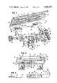
- FIG. 1is a perspective of an assembly embodying the invention with the base plate shown separated from the support body;
- FIG. 2is a fragmentary section taken approximately along the line 2--2 in FIG. 1;
- FIG. 3is an exploded view of certain of the parts appearing in FIG. 2;
- FIG. 4is a slightly enlarged side elevation of the assembly shown in FIG. 1 with a fragmentary portion broken away to show both lugs in FIG. 4;
- FIG. 5is a bottom plan view of the assembly showing the mechanism within the support body.
- an instrument lock-plate assembly 10having a base plate 11 and a support body 12 embodying the invention and suitable for mounting heavy motion picture or television cameras on a panhead 60.
- the base plate 11is elongated and adapted to be rigidly secured to the base of a camera or other instrument.
- the illustrated base plateis formed with three fore and aft spaced mounting holes 13 and a pair of mounting slots 14 so as to give considerable flexibility in mounting positions since any hole 13 in either slot 14 could be used to bolt the plate to the camera, with the camera axis running the length of the base plate 11.
- the support body 12is secured to the panhead 60 by a pair of U bolts 16 and nuts 17 that clamp serrated surfaces 18 to the mounting shaft 19 of the panhead in the usual fashion.
- the body 12is formed with left and right lugs 21 and 22 having transverse mounting holes 23 and 24, respectively, for receiving the transverse portions of handle shafts.
- Handle locking knobs 25are threaded into the body 12 so as to carry locking pins 26 into engagement with handle shafts fitted into the holes 23, 24.
- the mounting holes 23, 24have a diameter for receiving a handle shaft and are offset fore and aft a distance greater than the diameter of the holes so that handle shafts can be fitted from either left or right into either one of the holes 23, 24. If fitted from the left into the hole 24, the shaft would simply clear the rear of the lug 21.
- the lug 22is formed with a nonserrated passage hole 27 on the axis of the hole 23 as seen in FIG. 4 which has a fragmentary portion of the lug 22 adjacent the opening 27 broken away to reveal a portion of the other lug 21 which has the serrated opening 23.
- the user of the assembly 10thus has considerable flexibility in mounting one or two handles on the assembly and adjusting the handle or handles position.
- the base plate 11has parallel tapered ways 31, and the support body 12 has an upper surface 32 for receiving the plate 11 and opposed lugs 33 and 34 with undercut surfaces 35 to engage the tapered ways 31 and define a tongue-in-groove mating engagement between the base plate and the support body. Assuming some looseness between the ways 31 and the lug surfaces 35, the plate 11 can slide fore and aft on the upper surface 32. To limit such movement, there is interfitting between a projection 36 on the support body 12 and a groove 37 on the base plate 11.
- the projection 36is preferably at one end of the surface 32, and the plate 11 is formed with four grooves 37 symmetrically positioned so that the elongated plate can be mounted on the surface 32 aligned in either direction. Once mounted, the plate 11 can slide only the distance the projection 36 can move within one of the grooves 37.
- the lug 34 on one side of the support body 12is movable, and is mounted for movement both down to the plane of the upper surface, along arrows 41, as well as above the upper surface toward the opposed lugs 34, along arrows 42 (see also FIG. 5).
- the lug 34is biased up from the plane of the surface 32 so that the base plate 11 can engage the fixed lugs 33, press the movable lug 34 down against its bias, and have the lug 34 snap above the adjacent way 31 to lock the plate on the body.
- the lug 34is also manually movable toward the opposed lugs 33 so as to clamp the base plate 11 between the lugs 33, 34 and against the body upper surface 32.
- the lug 34is pivoted by a pin 43 on a member 44 slidably mounted in the body 12.
- the lug 34is moved in the direction of the arrows 42 by a pair of wedges 45 on an oppositely threaded shaft 46 carrying a manually turned knob 47.
- the wedges 45slide between aligned surfaces on the body 12 and tapered surfaces on the member 44 so that rotating the knob 47 in the direction of the arrow 48 draws the wedges 45 together so as to slide the member 44 in a straight line in the direction of the arrows 49, thereby pulling the movable lug 34 into clamping position against the base plate 11.
- the shaft 46passes through a slot 51 in the member 44, allowing the member clearance to shift.
- the threaded shaft 46 and wedge 45 arrangementprovides a strong, solid clamping action, with no possible release from a back force being exerted on the lug 34.
- the lug 34is biased through a stop 52 that is urged by a pair of helical springs 53 against a surface 54, thus biasing the lug counterclockwise as seen in FIGS. 2 and 3.
- the stop 52has a lip 55 that extends between the surface 54 and the midportion of the shaft 46. When the lug 34 pivots down against its bias, the stop lip 55 is urged toward the shaft 46. If the lip engages the shaft, the lug 34 can no longer pivot against the bias.
- the lug 34When used with a panhead such as the panhead 60 having a web 61 supporting a fluid casing at the side of the assembly, the lug 34 is formed with a notch 62 so that it can be moved down with the notch 52 straddling the web 61. This provides a further safety feature in that the notch 52 will not fit over the web unless the support body 12 is level on the panhead. If not level, interference between the lug and the web 61 prevents the lug 34 from unlocking. Therefore, connection and disconnection can only be accomplished if the plate 11 and the attached camera is in a level position.
- the support body 12is secured to the desired panhead which is mounted as desired.
- the base plate 11is securely fixed to the bottom of the camera to be used.
- the operatorafter assuring himself that the knob 47 has been rotated to free the lug 34 for downward pivoting movement, lifts the camera with this customarily being done from the left side of the camera with the lens pointing to the cameraman's left.
- the camerais slightly tilted so that the base plate 11 engages the lugs 33 at virtually any point along the length of the base plate, and then the camera is rocked to a level position whereupon the base plate 11 will engage and press down the lug 34 against its bias.
- the lug 34will snap over the adjacent plate way 31, and the projection 36 will engage an overlying slot 37, whereupon the camera is virtually locked on the support body.
- a quick turn of the knob 47will slightly shift the lug 34 so that it no longer can pivot downwardly, whereupon complete locking has been achieved.
- the cameramanmay then slide his camera fore and aft on the support body 12 to a point of balance and further slight rotation of the knob 47 will securely clamp the plate 11 on the body 12.
Landscapes
- Engineering & Computer Science (AREA)
- General Engineering & Computer Science (AREA)
- Mechanical Engineering (AREA)
- Accessories Of Cameras (AREA)
Abstract
Description
Claims (6)
Priority Applications (1)
| Application Number | Priority Date | Filing Date | Title |
|---|---|---|---|
| US06/275,811US4466595A (en) | 1981-06-22 | 1981-06-22 | Camera lock-plate assembly |
Applications Claiming Priority (1)
| Application Number | Priority Date | Filing Date | Title |
|---|---|---|---|
| US06/275,811US4466595A (en) | 1981-06-22 | 1981-06-22 | Camera lock-plate assembly |
Publications (1)
| Publication Number | Publication Date |
|---|---|
| US4466595Atrue US4466595A (en) | 1984-08-21 |
Family
ID=23053896
Family Applications (1)
| Application Number | Title | Priority Date | Filing Date |
|---|---|---|---|
| US06/275,811Expired - LifetimeUS4466595A (en) | 1981-06-22 | 1981-06-22 | Camera lock-plate assembly |
Country Status (1)
| Country | Link |
|---|---|
| US (1) | US4466595A (en) |
Cited By (31)
| Publication number | Priority date | Publication date | Assignee | Title |
|---|---|---|---|---|
| US4948086A (en)* | 1989-11-13 | 1990-08-14 | Richard Buol | Support apparatus |
| US4979709A (en)* | 1989-02-28 | 1990-12-25 | Heiwa Seiki Kogyo Co., Ltd. | Tripod head |
| US5056745A (en)* | 1989-03-06 | 1991-10-15 | Flight Research | Geared head and method for selective position of a camera |
| US5106039A (en)* | 1990-11-20 | 1992-04-21 | Metra Electronics Corporation | Keyed universal mounting kit for mounting a radio in an automotive dashboard |
| US5230490A (en)* | 1992-10-26 | 1993-07-27 | Saunders Photo/Graphic Inc. | Quick release camera mounting mechanism |
| GB2283830A (en)* | 1993-11-04 | 1995-05-17 | Grip House Ltd | Dovetailed camera mount |
| US5419520A (en)* | 1991-08-09 | 1995-05-30 | Heiwa Seiki Kogyo Co., Ltd. | Tripod head |
| US5601265A (en)* | 1994-05-17 | 1997-02-11 | Thomson Broadcast | Device for locking an apparatus on a support notably a camera on a tripod |
| EP0719591A3 (en)* | 1994-12-30 | 1998-04-01 | Nordson Corporation | Adhesive spray gun system with individually adjustable spray modules |
| US5737657A (en)* | 1995-11-17 | 1998-04-07 | Paddock; George K. | Adjustable platform having a quick release mechanism for use with a camera |
| US6196504B1 (en) | 1998-07-09 | 2001-03-06 | Maurice W. Lemke | Positive-lock-and-release device for camera mounting |
| US6209834B1 (en)* | 1999-04-12 | 2001-04-03 | Verimap Plus Inc. | Optical imaging mount apparatus |
| WO2002086376A1 (en)* | 2001-04-20 | 2002-10-31 | Sachtler Corporation Of America | Heavy-duty stabilized camera head with camera position sensing |
| EP1365187A1 (en)* | 2002-05-23 | 2003-11-26 | Swarovski Optik KG | Device for quick-fastening an apparatus to a support head |
| US20070084979A1 (en)* | 2005-08-10 | 2007-04-19 | Sachtler Gmbh & Co. Kg | Camera tripod head |
| US20090101773A1 (en)* | 2005-08-09 | 2009-04-23 | Yongjian Yang | Camera pan head having two clamps locked connector |
| US20090314907A1 (en)* | 2008-06-23 | 2009-12-24 | Romerein Robert L | Methods and apparatus for mounting devices |
| USD621436S1 (en) | 2009-04-22 | 2010-08-10 | Clinton Reed Chidester | Receiving base for a quick connect stand mounting system |
| USD621865S1 (en) | 2009-04-22 | 2010-08-17 | Clinton Reed Chidester | Connection insert for a quick connect stand mounting system |
| USD709939S1 (en)* | 2011-09-20 | 2014-07-29 | Nikon Corporation | Adapter for camera accessories |
| US8827219B2 (en)* | 2011-12-09 | 2014-09-09 | Kessler Crane, Inc. | Quick release plate |
| US20150267858A1 (en)* | 2014-03-18 | 2015-09-24 | Wooden Camera, Inc. | Releasable Support Mounts and Related Methods |
| US9736376B1 (en)* | 2014-04-03 | 2017-08-15 | The Tiffen Company, Llc | Tilt head, camera stage, multi-post monitor mount and camera stabilizer encompassing the same |
| CN110546421A (en)* | 2017-04-21 | 2019-12-06 | 西普有限责任公司 | Quick Release Camera Mount |
| CN115031093A (en)* | 2021-12-31 | 2022-09-09 | 上海墨卓生物科技有限公司 | Chip support for single cell sequencer |
| JP2023134479A (en)* | 2019-05-13 | 2023-09-27 | ピーク デザイン | Compact high-aspect-ratio camera tripod |
| US20240036444A1 (en)* | 2005-01-07 | 2024-02-01 | Really Right Stuff, Llc | Panoramic camera mount |
| WO2024038066A1 (en)* | 2022-08-18 | 2024-02-22 | Koninklijke Philips N.V. | Device for fixing defibrillator |
| US20240337350A1 (en)* | 2023-04-10 | 2024-10-10 | Tilta Inc. | Universal dovetail mount |
| US20250075845A1 (en)* | 2023-08-31 | 2025-03-06 | Zhongshan Jingge Electronic Technology Co., Ltd. | Quick-Release Tripod Head |
| US12416850B1 (en) | 2019-05-13 | 2025-09-16 | Peak Design | Close-pack, high-aspect-ratio camera tripod |
Citations (9)
| Publication number | Priority date | Publication date | Assignee | Title |
|---|---|---|---|---|
| US454553A (en)* | 1891-06-23 | Book-supporting attachment for furniture | ||
| US1021037A (en)* | 1911-11-25 | 1912-03-26 | Frank Washburn Buffum | Oil-can holder. |
| US1049974A (en)* | 1913-01-07 | George Edwin Bailie | Pressure-gage holder or bracket. | |
| US2448752A (en)* | 1945-07-26 | 1948-09-07 | Simon P Wagner | Fishing rod holder |
| US2911700A (en)* | 1954-06-22 | 1959-11-10 | Duro Metal Products Co | Separable mountings for electric motors or the like |
| US2962251A (en)* | 1957-11-29 | 1960-11-29 | Karpf Nikolaus | Tilting tripod-head |
| US2962135A (en)* | 1958-10-13 | 1960-11-29 | North American Aviation Inc | Mounting device |
| DE2852034A1 (en)* | 1977-12-02 | 1979-07-05 | Michio Kawazoe | CAMERA TRIPOD |
| US4316592A (en)* | 1980-06-20 | 1982-02-23 | Jett Earl A | Camera-to-tripod alignment holder |
- 1981
- 1981-06-22USUS06/275,811patent/US4466595A/ennot_activeExpired - Lifetime
Patent Citations (9)
| Publication number | Priority date | Publication date | Assignee | Title |
|---|---|---|---|---|
| US454553A (en)* | 1891-06-23 | Book-supporting attachment for furniture | ||
| US1049974A (en)* | 1913-01-07 | George Edwin Bailie | Pressure-gage holder or bracket. | |
| US1021037A (en)* | 1911-11-25 | 1912-03-26 | Frank Washburn Buffum | Oil-can holder. |
| US2448752A (en)* | 1945-07-26 | 1948-09-07 | Simon P Wagner | Fishing rod holder |
| US2911700A (en)* | 1954-06-22 | 1959-11-10 | Duro Metal Products Co | Separable mountings for electric motors or the like |
| US2962251A (en)* | 1957-11-29 | 1960-11-29 | Karpf Nikolaus | Tilting tripod-head |
| US2962135A (en)* | 1958-10-13 | 1960-11-29 | North American Aviation Inc | Mounting device |
| DE2852034A1 (en)* | 1977-12-02 | 1979-07-05 | Michio Kawazoe | CAMERA TRIPOD |
| US4316592A (en)* | 1980-06-20 | 1982-02-23 | Jett Earl A | Camera-to-tripod alignment holder |
Cited By (46)
| Publication number | Priority date | Publication date | Assignee | Title |
|---|---|---|---|---|
| US4979709A (en)* | 1989-02-28 | 1990-12-25 | Heiwa Seiki Kogyo Co., Ltd. | Tripod head |
| US5056745A (en)* | 1989-03-06 | 1991-10-15 | Flight Research | Geared head and method for selective position of a camera |
| US4948086A (en)* | 1989-11-13 | 1990-08-14 | Richard Buol | Support apparatus |
| US5106039A (en)* | 1990-11-20 | 1992-04-21 | Metra Electronics Corporation | Keyed universal mounting kit for mounting a radio in an automotive dashboard |
| US5419520A (en)* | 1991-08-09 | 1995-05-30 | Heiwa Seiki Kogyo Co., Ltd. | Tripod head |
| US5429332A (en)* | 1991-08-09 | 1995-07-04 | Heiwa Seiki Kogyo Co., Ltd. | Sliding plate for securing camera |
| US5230490A (en)* | 1992-10-26 | 1993-07-27 | Saunders Photo/Graphic Inc. | Quick release camera mounting mechanism |
| GB2283830A (en)* | 1993-11-04 | 1995-05-17 | Grip House Ltd | Dovetailed camera mount |
| GB2283830B (en)* | 1993-11-04 | 1997-06-11 | Grip House Ltd | Camera mounting assembly |
| US5601265A (en)* | 1994-05-17 | 1997-02-11 | Thomson Broadcast | Device for locking an apparatus on a support notably a camera on a tripod |
| EP0719591A3 (en)* | 1994-12-30 | 1998-04-01 | Nordson Corporation | Adhesive spray gun system with individually adjustable spray modules |
| US5737657A (en)* | 1995-11-17 | 1998-04-07 | Paddock; George K. | Adjustable platform having a quick release mechanism for use with a camera |
| US6196504B1 (en) | 1998-07-09 | 2001-03-06 | Maurice W. Lemke | Positive-lock-and-release device for camera mounting |
| US6209834B1 (en)* | 1999-04-12 | 2001-04-03 | Verimap Plus Inc. | Optical imaging mount apparatus |
| WO2002086376A1 (en)* | 2001-04-20 | 2002-10-31 | Sachtler Corporation Of America | Heavy-duty stabilized camera head with camera position sensing |
| AU2002307484B9 (en)* | 2001-04-20 | 2002-11-05 | Camera Dynamics Inc. | Heavy-duty stabilized camera head with camera position sensing |
| US20040113033A1 (en)* | 2001-04-20 | 2004-06-17 | Johnson Joel W. | Heavy-duty stabilized camera head with camera position sensing |
| AU2002307484B2 (en)* | 2001-04-20 | 2007-04-26 | Camera Dynamics Inc. | Heavy-duty stabilized camera head with camera position sensing |
| US7287731B2 (en) | 2001-04-20 | 2007-10-30 | Camera Dynamics Inc. | Heavy-duty stabilized camera head with camera position sensing |
| EP1365187A1 (en)* | 2002-05-23 | 2003-11-26 | Swarovski Optik KG | Device for quick-fastening an apparatus to a support head |
| US20240036444A1 (en)* | 2005-01-07 | 2024-02-01 | Really Right Stuff, Llc | Panoramic camera mount |
| US20090101773A1 (en)* | 2005-08-09 | 2009-04-23 | Yongjian Yang | Camera pan head having two clamps locked connector |
| US20070084979A1 (en)* | 2005-08-10 | 2007-04-19 | Sachtler Gmbh & Co. Kg | Camera tripod head |
| US20090314907A1 (en)* | 2008-06-23 | 2009-12-24 | Romerein Robert L | Methods and apparatus for mounting devices |
| US20110031365A1 (en)* | 2008-06-23 | 2011-02-10 | Romerein Robert L | Methods and apparatus for mounting devices |
| US7918430B2 (en)* | 2008-06-23 | 2011-04-05 | Extreme Broadband Engineering, Llc | Methods and apparatus for mounting devices |
| US7963497B2 (en) | 2008-06-23 | 2011-06-21 | Extreme Broadband Engineering, Llc | Methods and apparatus for mounting devices |
| US20110186694A1 (en)* | 2008-06-23 | 2011-08-04 | Romerein Robert L | Methods and apparatus for mounting devices |
| US8136787B2 (en) | 2008-06-23 | 2012-03-20 | Extreme Broadband Engineering, Llc | Methods and apparatus for mounting devices |
| US8152125B2 (en) | 2008-06-23 | 2012-04-10 | Extreme Broadband Engineering, Llc. | Methods and apparatus for mounting devices |
| USD621865S1 (en) | 2009-04-22 | 2010-08-17 | Clinton Reed Chidester | Connection insert for a quick connect stand mounting system |
| USD621436S1 (en) | 2009-04-22 | 2010-08-10 | Clinton Reed Chidester | Receiving base for a quick connect stand mounting system |
| USD709939S1 (en)* | 2011-09-20 | 2014-07-29 | Nikon Corporation | Adapter for camera accessories |
| US8827219B2 (en)* | 2011-12-09 | 2014-09-09 | Kessler Crane, Inc. | Quick release plate |
| US9188274B2 (en)* | 2014-03-18 | 2015-11-17 | Wooden Camera, Inc. | Releasable support mounts and related methods |
| US20150267858A1 (en)* | 2014-03-18 | 2015-09-24 | Wooden Camera, Inc. | Releasable Support Mounts and Related Methods |
| US9736376B1 (en)* | 2014-04-03 | 2017-08-15 | The Tiffen Company, Llc | Tilt head, camera stage, multi-post monitor mount and camera stabilizer encompassing the same |
| CN110546421A (en)* | 2017-04-21 | 2019-12-06 | 西普有限责任公司 | Quick Release Camera Mount |
| US11061302B2 (en) | 2017-04-21 | 2021-07-13 | Syrp Limited | Quick release camera mount |
| JP2023134479A (en)* | 2019-05-13 | 2023-09-27 | ピーク デザイン | Compact high-aspect-ratio camera tripod |
| US12416850B1 (en) | 2019-05-13 | 2025-09-16 | Peak Design | Close-pack, high-aspect-ratio camera tripod |
| CN115031093A (en)* | 2021-12-31 | 2022-09-09 | 上海墨卓生物科技有限公司 | Chip support for single cell sequencer |
| WO2024038066A1 (en)* | 2022-08-18 | 2024-02-22 | Koninklijke Philips N.V. | Device for fixing defibrillator |
| US20240337350A1 (en)* | 2023-04-10 | 2024-10-10 | Tilta Inc. | Universal dovetail mount |
| US12253209B2 (en)* | 2023-04-10 | 2025-03-18 | Tilta Inc. | Universal dovetail mount |
| US20250075845A1 (en)* | 2023-08-31 | 2025-03-06 | Zhongshan Jingge Electronic Technology Co., Ltd. | Quick-Release Tripod Head |
Similar Documents
| Publication | Publication Date | Title |
|---|---|---|
| US4466595A (en) | Camera lock-plate assembly | |
| US4320885A (en) | Coupling device | |
| CN101861491B (en) | PTZ | |
| US2168988A (en) | Adjustable tripod head | |
| US5503357A (en) | Lock mechanism for tripod legs | |
| EP0070337B1 (en) | A tiltable and/or rotatable support for a display device | |
| US6234690B1 (en) | Camera quick-release device | |
| US6154255A (en) | Mount shift apparatus of lens for CCTV camera | |
| US6827319B2 (en) | Apparatus for quick fixation of a device to a tripod head | |
| US5732912A (en) | Rod locking apparatus and camera stand employing this apparatus | |
| KR101516060B1 (en) | Quick clamping apparatus for optical devices | |
| JPS5814887A (en) | Tiltable/rotatable support base | |
| US4249817A (en) | Adjustable head for tripods | |
| JPS589216Y2 (en) | Holding device for camera mounting bracket | |
| US6354544B1 (en) | Adjustable camera mounting device | |
| EP0566660A1 (en) | Improved optical mounting apparatus | |
| EP0737886B1 (en) | Viewfinder mounting for video camera | |
| US10527387B1 (en) | Method and apparatus for installing, repositioning, swapping, or removing a foregrip | |
| CN215807465U (en) | Adjusting structure and quick-release device | |
| JP4620226B2 (en) | Adjustable leg device | |
| GB2273368A (en) | Camera tripod head rotatable about two perpendicular axes with handle | |
| US4476994A (en) | Lid latching apparatus | |
| US4316592A (en) | Camera-to-tripod alignment holder | |
| GB1563433A (en) | Device for adjustably locking a movable part relative to a fixed structure | |
| US6027258A (en) | Steady camera mount system |
Legal Events
| Date | Code | Title | Description |
|---|---|---|---|
| STCF | Information on status: patent grant | Free format text:PATENTED CASE | |
| FEPP | Fee payment procedure | Free format text:PAYOR NUMBER ASSIGNED (ORIGINAL EVENT CODE: ASPN); ENTITY STATUS OF PATENT OWNER: SMALL ENTITY | |
| FPAY | Fee payment | Year of fee payment:4 | |
| AS | Assignment | Owner name:Q-CO INDUSTRIES, INC., A CORP. OF NY, NEW YORK Free format text:ASSIGNMENT OF ASSIGNORS INTEREST.;ASSIGNOR:O'CONNOR, CHADWELL;REEL/FRAME:005268/0986 Effective date:19900308 | |
| FPAY | Fee payment | Year of fee payment:8 | |
| FPAY | Fee payment | Year of fee payment:12 | |
| AS | Assignment | Owner name:AUTOCUE, INC., NEW YORK Free format text:CHANGE OF NAME;ASSIGNOR:Q-CO. INDUSTRIES, INC.;REEL/FRAME:010113/0581 Effective date:19981027 | |
| AS | Assignment | Owner name:3I PLC, ENGLAND Free format text:SECURITY INTEREST;ASSIGNOR:AUTOCUE, INC.;REEL/FRAME:011523/0249 Effective date:20000727 Owner name:NATIONAL WESTMINSTER BANK PLC, ENGLAND Free format text:SECURITY INTEREST;ASSIGNOR:AUTOCUE, INC.;REEL/FRAME:011523/0276 Effective date:20000727 | |
| AS | Assignment | Owner name:AUTOCUE, INC., NEW YORK Free format text:TERMINATION AND RELEASE OF SECURITY INTERESTS IN PATENTS;ASSIGNOR:NATIONAL WESTMINSTER BANK PLC;REEL/FRAME:014972/0242 Effective date:20030205 |