US4466273A - Leak detection system - Google Patents
Leak detection systemDownload PDFInfo
- Publication number
- US4466273A US4466273AUS06/292,121US29212181AUS4466273AUS 4466273 AUS4466273 AUS 4466273AUS 29212181 AUS29212181 AUS 29212181AUS 4466273 AUS4466273 AUS 4466273A
- Authority
- US
- United States
- Prior art keywords
- fitting
- casing
- fluid
- valve
- suspect
- Prior art date
- Legal status (The legal status is an assumption and is not a legal conclusion. Google has not performed a legal analysis and makes no representation as to the accuracy of the status listed.)
- Expired - Lifetime
Links
Images


Classifications
- E—FIXED CONSTRUCTIONS
- E21—EARTH OR ROCK DRILLING; MINING
- E21B—EARTH OR ROCK DRILLING; OBTAINING OIL, GAS, WATER, SOLUBLE OR MELTABLE MATERIALS OR A SLURRY OF MINERALS FROM WELLS
- E21B47/00—Survey of boreholes or wells
- E21B47/10—Locating fluid leaks, intrusions or movements
- E—FIXED CONSTRUCTIONS
- E21—EARTH OR ROCK DRILLING; MINING
- E21B—EARTH OR ROCK DRILLING; OBTAINING OIL, GAS, WATER, SOLUBLE OR MELTABLE MATERIALS OR A SLURRY OF MINERALS FROM WELLS
- E21B33/00—Sealing or packing boreholes or wells
- E21B33/02—Surface sealing or packing
- E21B33/03—Well heads; Setting-up thereof
- E—FIXED CONSTRUCTIONS
- E21—EARTH OR ROCK DRILLING; MINING
- E21B—EARTH OR ROCK DRILLING; OBTAINING OIL, GAS, WATER, SOLUBLE OR MELTABLE MATERIALS OR A SLURRY OF MINERALS FROM WELLS
- E21B43/00—Methods or apparatus for obtaining oil, gas, water, soluble or meltable materials or a slurry of minerals from wells
- F—MECHANICAL ENGINEERING; LIGHTING; HEATING; WEAPONS; BLASTING
- F17—STORING OR DISTRIBUTING GASES OR LIQUIDS
- F17D—PIPE-LINE SYSTEMS; PIPE-LINES
- F17D5/00—Protection or supervision of installations
- F17D5/02—Preventing, monitoring, or locating loss
- G—PHYSICS
- G01—MEASURING; TESTING
- G01M—TESTING STATIC OR DYNAMIC BALANCE OF MACHINES OR STRUCTURES; TESTING OF STRUCTURES OR APPARATUS, NOT OTHERWISE PROVIDED FOR
- G01M3/00—Investigating fluid-tightness of structures
- G01M3/02—Investigating fluid-tightness of structures by using fluid or vacuum
- G01M3/26—Investigating fluid-tightness of structures by using fluid or vacuum by measuring rate of loss or gain of fluid, e.g. by pressure-responsive devices, by flow detectors
- G01M3/28—Investigating fluid-tightness of structures by using fluid or vacuum by measuring rate of loss or gain of fluid, e.g. by pressure-responsive devices, by flow detectors for pipes, cables or tubes; for pipe joints or seals; for valves ; for welds
- G01M3/2853—Investigating fluid-tightness of structures by using fluid or vacuum by measuring rate of loss or gain of fluid, e.g. by pressure-responsive devices, by flow detectors for pipes, cables or tubes; for pipe joints or seals; for valves ; for welds for pipe joints or seals
- G01M3/2861—Investigating fluid-tightness of structures by using fluid or vacuum by measuring rate of loss or gain of fluid, e.g. by pressure-responsive devices, by flow detectors for pipes, cables or tubes; for pipe joints or seals; for valves ; for welds for pipe joints or seals for pipe sections by testing its exterior surface
- F—MECHANICAL ENGINEERING; LIGHTING; HEATING; WEAPONS; BLASTING
- F16—ENGINEERING ELEMENTS AND UNITS; GENERAL MEASURES FOR PRODUCING AND MAINTAINING EFFECTIVE FUNCTIONING OF MACHINES OR INSTALLATIONS; THERMAL INSULATION IN GENERAL
- F16L—PIPES; JOINTS OR FITTINGS FOR PIPES; SUPPORTS FOR PIPES, CABLES OR PROTECTIVE TUBING; MEANS FOR THERMAL INSULATION IN GENERAL
- F16L2201/00—Special arrangements for pipe couplings
- F16L2201/30—Detecting leaks
Definitions
- the present inventionrelates to piping and piping control systems, but more particularly, the present invention relates to the detection of leaks in the fitting portion of piping systems and the subsequent closure of the valves and like controls coincident with the occurrence of such a leak. Even more particularly, the present invention relates to a portable apparatus for detecting leaks in a suspect fitting portion of a pipeline with a bladder structure being portable and attachable to any existing piping system in a sealable fashion, the bladder thereafter collecting leaks.
- fittingsIn all piping systems, there is utilized generally a number of "fittings" which are used to configure the pipline or piping system to a desired chemical plant, or to the terrain across which it is flowing, or otherwise to change the pipeline configuration and position. Such fittings are known in the art as elbows, tees, crosses, valves, flanges, and the like.
- a fittingis generally referred to hereinafter as any portion of a pipeline which is connectable to a normal pipe joint, the fitting being a portion of the pipeline which can create turbulence and which can be a spot for potential leaks.
- Leaks in fittingsare generally created by corrosion or mechanical deterioration. This is often seen in the oil and gas industry where natural gas and/or oil flowing from a well is often combined with sand and the flowing produces a sandblasting effect. This sandblasting effect especially eats away at elbows, tees, choke jackets, and valves when the pipeline makes a turn. It is known in the art that turbulence is increased at such turning points in the pipeline.
- a wellIn the production of natural gas, a well is normally drilled with a length of pipe known as a "drill string".
- the drill pipeis individually made up of sections which can be, for example, thirty feet (30').
- the drill pipeis enclosed normally in a casing which is also welded or jointed. Casing is then cemented into place from the bottom up.
- the crewinstalls a master valve that may be closed quickly and surely to shut off the flow of gas. Above this valve is placed a "Christmas tree".
- a Christmas treeis merely an assembly of pipes and valves that allows the gas to flow into gathering lines. These gather the output of several wells and carry the fuel to the cross-country pipelines for remote transmission of the gas. It is to this general field that the present invention is directed.
- the present inventionprovides a simple and economical system for the detection of minute leaks in flow lines, and a method for the shut-off of flow within the line if a catastrophic failure of the line occurs.
- a deviceis especially important in the oil and gas industry, and in the transmission of natural gas where pressures developed within flow lines can be quite high.
- the present inventionprovides a portable bladder which can be quickly attached and jacketed into position around a particular fitting in any existing piping system which fitting may be suspect of subject to damage.
- the bladdercould be placed around the fittings which would experience a maximum amount of turbulence, mechanical deterioration, or corrosion.
- the present inventionsolves all these prior art problems and shortcomings by providing a portable bladder apparatus which is comprised generally of a pair of bladder shell halves which can be fitted together in a sealable fashion about a portion of an existent pipeline (such as an elbow or like fitting) where leaks may occur.
- the bladderprovides a pair of shell sections, each section having sealing mating surfaces which correspond to one another and join together in an encapsulating sealing fashion about the suspect fittings.
- the bladdercould be manufactured in a variety of desired shapes so as to properly encapsulate the subject fitting which is suspect for corrosion, mechanical deterioration, or leakage.
- a valve apparatus or regulatorwhich "senses" the presence of a leak and can be through gas instrumentation, for example, thereafter close a valve, for example, thus shutting off the flow of fluid through the pipeline and avoiding continued leakage and in the case of dangerous, volatile or hazardous materials, a possible catastrophe.
- FIG. 1is a schematic view of a typical oil and gas well illustrating the master valve and pipe assembly at the top portion of the well;
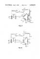
- FIG. 2is a schematic diagram of the preferred embodiment of the apparatus of the present invention.
- FIG. 3is a schematic diagram of an alternative embodiment of the apparatus of the present invention.
- FIG. 4is a sectional view of a typical choke jacket with the preferred embodiment of the apparatus of the present invention attached thereto in a sealable fashion;
- FIG. 4Ais a prospective exploded view of the bladder portion of the preferred embodiment of the apparatus of the present invention illustrating the pipe claps for holding the bladder to the suspect fitting in a sealable fashion;
- FIG. 5is a sectional view taken along lines 5--5 of FIG. 4A.
- FIG. 1illustrates a typical piping system with which the present invention has application, the system being a conventional oil and gas well showing a Christmas tree 20 mounted on the oil and gas well 22 itself.
- oil and gasenters the bottom portion of the well through screen pipe 23 and moves upwardly through tubing 24 to Christmas tree 20.
- Christmas tree 20is attached at casing assembly 25 with, for example, a flanged connection.
- the gasflows upwardly (see arrows) through Christmas tree 20 and passes laterally through manumatic valves 26 and then through choke jackets 28.
- Choke jacket 28is thus “suspect" in that the mechanically erosive effect of flow can eventually cause minute leaks which continuously grow until failure of the fitting or choke jacket occurs with the escape of volatile and polluting oil/gas presenting a hazard to property, lives and the environment.
- FIG. 1illustrates the portion of the oil and gas well to which the present invention could be directed in an exemplary installation, (i.e., the Christmas tree).
- the present inventioncould be applied to any piping situation where a particular fitting or section of pipe is subject to corrosion or failure and subsequent leaks.
- the present inventionwould be particularly useful in hazardous industries where even minute leaks would be either harmful, wasteful or even disastrous to property, lives, and the environment.
- the Christmas tree 20 shown in FIG. 1is provided with manumatic valves 26 which control the flow of natural gas from the well 22 to transmission pipelines. As can be seen by the arrows in FIGS. 1, 2 and 3, the gas flows upwardly and then laterally through valves 26 to choke jackets 28. Choke jackets 28 often experience high turbulence and corresponding mechanical erosion and therefore can be a potential source of leaks.
- FIGS. 2 and 3illustrate schematic piping diagrams of the preferred embodiment and alternative embodiments of the apparatus of the present invention illustrating their connection with the manumatic valves 26 and choke jacket 28.
- FIG. 2provides the preferred embodiment of the apparatus of the present invention where a rupture of bladder 12 occurs often, a leak from choke jacket 28 is collected within bladder 12.
- manumatic valve 26which is held in an open position by means of a supply of instrumentation control fluid flowing through conduit 16.
- Conduit 16passes through controller 14 which can be a CRBBM type controller as manufactured by U.S.I. Controller 14 is held in a posture which allows high pressure fluid 16 to pass therethrough in order to maintain valve 26 in an open position as long as regulator 14 additionally receives low pressure control fluid through supply line 10. Interruption of instrumentation control fluid to controller 14 causes the controller to "shift" and interrupt the supply of instrumentation control fluid to valve 26.
- valve 26requires a supply of control fluid to operate, it can be seen that an interruption in the supply of instrumentation control fluid in conduit 16 causes the valve 26 to close, halting the flow of fluids such as natural gas therethrough.
- supply conduit 10feeds control fluid to bladder 12 and thereafter to regulator 14. It can be seen that a rupture of bladder 12 (as will occur when a leak from choke jacket 28 fills bladder 12) will interrupt the flow of instrumentation control fluid to regulator 14.
- bladder 12is shown encasing choke jacket 28, but it can be used on any suspect piping fitting where erosion could produce the occurrence of leaks from the fitting at any time without notice.
- Bladder 12is attached to a suspect fitting such as a choke jacket 28 by means of, for example, a plurality of pipe clamps 30.
- the bladderwould be generally open at one end portion, as it is illustrated in FIG. 4A, so that it could slip over the choke jacket.
- the slitted portion designated generally by the numeral 40 in FIG. 4Awould be sealed by gluing or like closure while the openings 42-44 would be sealed by means of clamps 30, as is illustrated in FIG. 4A.
- a sealable encapsulating bladder 12would be provided about any suspect fitting, with the end result that a leak occurring from the fitting 28 would be collected by the bladder and thereafter transmitted through a suitable conduit 45 to shut off apparatus or like indicating structure, as will be discussed more fully hereinafter, and as was illustrated heretofore in FIGS. 2 and 3.
- an air space 13can be provided between bladder 12 and fitting 28 into which air space leaks from fitting 28 will flow and thus be collected.
- Air space 13likewise, provides a space into which instrumentation air can flow through conduits 10 enroute to controller 14, as was described more fully above.
- FIG. 3illustrates an alternative embodiment of the apparatus of the present invention which shows a typical manumatic control valve 26 controlling the flow of oil and gas from line 27 which leaves Christmas tree 20 (note FIG. 3).
- An instrumentation gas supply fed through conduit 16 and towards valve 26maintains valve 26 in an "open" position.
- Regulator 15can be, for example, a Fisher Model 164-A regulator set at approximately five to ten pounds in an exemplary installation.
- Such a regulator as the Fisher Model 164-Ais a threeway pneumatic switching valve. It is spring loaded and diaphragm actuated. A control connection to the regulator applies sufficient pressure to the diaphragm causing a valve plug within to shift and change the route of fluids flowing through the regulator.
- a normally open port within regulator 15allows the control fluid supply to pass through conduit 16 and maintain valve 26 in an "open" position. If it is undesirable to maintain a pressure on bladder 12, as is done in the preferred embodiment, the alternative embodiment provides no pressure on bladder 12, but rather bleeds pressure through line 10 in the event of a leak within fitting 28. It can be seen that the leak from fitting 28 will be caught within bladder 12 and flow through conduit 10, causing a buildup of pressure within both bladder 12 and line 13 and shifting a piston or like valving member within regulator 15 to close the control fluid supply in conduit 16. The lack of this control fluid to valve 26 causes it to close (as is known in the art).
- the embodiments of the present invention above disclosedprovide a simple solution for the problem of early detection of leaks in suspect fittings of flow lines, for example, as in the choke jacket of a Christmas tree portion of a natural gas well.
- bladder 12would be attached in an encapsulating fashion about the suspect fitting, such as a choke jacket 28 by using clamps 30, as is illustrated in FIG. 3.
- Clamps 30can be, for example, generally "U” shape pipe clamps as is illustrated more particularly in FIGS. 4 and 4A.
- FIGS. 4, 4A and 5illustrate more particularly, the structure of bladder 12.
- Bladder 12is in the preferred embodiment comprised of a generally flexible material such as, rubber, plastic film, or the like.
- Such a pliable structurecould easily be formed around a suspect fitting as is illustrated in FIG. 4 with a typical oil field choke jacket 28.
- each clamp 30could be, for example, comprised of a pair of generally "U" shaped clamp halves 30, 32, with each clamp half providing outwardly depending tabs 34 with openings 35 therethrough.
- Clamp halves 31, 32could be assembled by using a bolted connection 40 as illustrated best in FIG. 4A.
- a bladder 12is provided which is shaped to generally fit over and encapsulate an oil field choke jacket 28.
- a pair of slits 40, 46are provided which will allow bladder 12 to be split partially into a pair of bladder halves 12A and 12B.
- Bladder halves 12A and 12Bwould be separated by hand and the entire bladder structure 12 pulled over the suspect fitting such as, choke jacket 28 and thereafter sealed using pipe clamps 30 as aforementioned.
- Slits 40 and 46could be sealed by using glue or like suitable means. A rubber cement or rubber glue could be used to seal slits 46 and 40, if desirable.
- the entire bladder structure 12could be totally split into two separate halves which are not connected at all, if desirable. In such an instance, each half would be mounted to the pipe suspect fitting and thereafter glued along the slits 40 and 46 with the sealable connection to fitting 28 being completed using pipe clamps 30.
- FIGS. 4 and 5there is seen a conduit 10 which is integrally attached to bladder 12.
- Each conduit line 10is schematically illustrated in FIGS. 2 and 3 and provides a conduit which instrumentation gas (FIG. 2) or a collected leak (FIG. 3) could pass to perform the desired indication and shut off function.
- the bladder structure 12 as taught by the present inventionis totally portable and could easily be attached to any existing piping system while the piping system is in operation.
- the present inventionprovides a leak detection and shut off apparatus which would easily be added to existing gas wells, oil wells, or like piping systems where fittings are suspect and where leaks might occur with the result being possibly a loss of life or like catastrophe.
- conduit 10could connect to a section of conventional tubing 50 with the connection being perfected in a sealable fashion using clamps 30 and a bolted 48 connection.
- the apparatus of the present inventionis totally portable and capable of operating without the intervention of a human operator, and can thus avert the possiblity of any hazards caused by leakage, which can eventually lead to explosion, fire, or like threats to property, life, and the environment.
- the present inventionwould allow a flow line control valve to be shut off, and stop the flow of gas from a gas well and thus avert the escape of gas through any minute leak which might occur in a suspect fitting which leak over a period of time in a remote area could grow with the continued escape of natural gas or like volatile fluid posing a hazard to both individuals and the environment.
- Such an early leak detection and valve closure systemwould save the unnecessary and wasteful loss of much fuel before the leak is detected, even in the case where a disaster does not occur.
- line 13 leaving bladder 12provides an instrumentation line which would operate any pressure or volume change responsive alarm, pressure guage or like indicator.
- the fluidwould be trapped in bladder 12 and either pressure or volume or both would be transmitted to line 13 for operation of the desired indicator--the leak being detected.
- FIG. 6best illustrates an additional embodiment of the apparatus of the present invention generally designated by the number 110.
- a typical pipeline 111which is comprised of a plurality of piping joints 111a through 111d adjoined at their end portion by attachments such as bolting or welding to a conventional type cross-fitting 112.
- This embodiment of the leak detection apparatus of the invention designated by the numeral 110is comprised in FIG. 6 of a first casing half 113 and a second casing half 114.
- Each casing half 113 and 114would provide a generally curved casing wall 115 having a thickness as needed to accommodate pressures within as will be described more fully hereinafter.
- the casing halves 113 and 114further provided with flanges 116 as is illustrated in FIG. 6. Opening 118 is provided in each flange 116, which openings will accommodate bolt 120 and nut 121 as shown in FIG. 6, thereby completing a seal.
- sealing disc 130which occupies an opening 124 when halves 113 and 114 are assembled.
- Sealing disc 130is of a pliable material, such as rubber, for sealing between pipe 111 and opening 124 when valve 113 and 114 are bolted together.
- sealing base 124is adapted with groove 125 so that it may be fitted around the length of the pipe 111, and fitted in place.
- a rubber base adhesive sealantcan be applied between the exterior circumference 127 of base 130 to more effectively seal the joints.
- Disc 130also provides for annular shoulder 129 which acts as a peripheral sealing connecting surface when the apparatus 110 is assembled which would insert into groove 111 of apparatus 110, further establishing the seal therebetween.
- a regulator 140such as a typical regulator valve, will be discussed more fully hereinafter, is adapted to apparatus 110 at point 112.
- the regulator 140will sense the presence of a leak from the fitting housed within leak detection apparatus 110 and use the leak to perform a desired instrumentation function, such as shutting off the valve.
- the encapsulating casing halves 113 and 114 as showncan be sealably attached to about any fitting such as a cross joint, for example, which is suspect or subject to leakage as often the case where pipelines carrying corrosive or mechanically abrasive material making turns through fittings or otherwise creating turbulance within the fitting that can cause a leak.
- a suitable regulator or control valve 140can be attached to apparatus 110 in a sealable fashion at point 112. After the sealable attachment of casing halves 113 and 114 with the suspect fitting is accomplished, leaks occurring from the fitting can then be collected within the rigid casing 110 and there accumulation producing an increase in pressure and increase in volume which could then activate the regulator or control valve 140.
- the present inventioncan be used in a plurality of fittings as are known in the pipeline and the oil and gas art.
- the present inventioncan be used with L-bolts, tees, valves, crosses and like fittings.
- the present inventionprovides a leak detection apparatus which provides a rigid bladder casing 110 which can be reasonably fixed about any fitting within a conventional pipe system, which fitting may be subject to be damaged by mechanical or chemical erosion and subsequent leakage.
- ring disc 130would be inserted into the space between pipeline sections 111a through 111d and openings 24 to form a sealable connection between pipeline sections 111a through 111d and rigid bladder casing 110.
- bladder casing 110is comprised of a pair of casing halves 113 and 114.
- Each casing half 113 and 114is comprised of a curved bladder casing wall 115 having in the preferred embodiment four circular arcuate side ribs 113a which form openings 124 when casing halves 113 and 114 are assembled corresponding upper and lower side ribs 113a registering and abutting to form the desired circular openings 124.
- Each casing half 113 and 114is further comprised of a plurality of sealing flanges 116 which are generally rectangular and flat, and provide a means for assembling casing halves 113 and 114 together in a sealable fashion about a suspect fitting where corrosion and leakage may appear.
- Each flange 116provides an inner sealing surface 128 as can be seen in FIG. 6.
- a bolt 120 and nut 122is shown as a connection for allowing removal of the entire leak detection apparatus 110 as desired with minimal time and labor involved.
Landscapes
- Engineering & Computer Science (AREA)
- Geology (AREA)
- Life Sciences & Earth Sciences (AREA)
- Mining & Mineral Resources (AREA)
- Physics & Mathematics (AREA)
- Environmental & Geological Engineering (AREA)
- Fluid Mechanics (AREA)
- General Life Sciences & Earth Sciences (AREA)
- Geochemistry & Mineralogy (AREA)
- Mechanical Engineering (AREA)
- General Engineering & Computer Science (AREA)
- General Physics & Mathematics (AREA)
- Geophysics (AREA)
- Pipeline Systems (AREA)
- Examining Or Testing Airtightness (AREA)
Abstract
Description
______________________________________ PRIOR ART PATENTS U.S. Pat. No. Inventor(s) Issue Date ______________________________________ 2,280,140 J. H. Wilson 04/21/42 2,607,225 P. H. Biscoe 01/23/48 2,765,801 F. E. Selim 10/09/56 2,937,520 A. Bell 05/24/60 3,339,415 W. Wild 09/05/67 3,339,728 A. R. Taylor 09/03/68 ______________________________________
Claims (8)
Priority Applications (1)
| Application Number | Priority Date | Filing Date | Title |
|---|---|---|---|
| US06/292,121US4466273A (en) | 1978-10-23 | 1980-10-29 | Leak detection system |
Applications Claiming Priority (2)
| Application Number | Priority Date | Filing Date | Title |
|---|---|---|---|
| US05/954,578US4232736A (en) | 1978-10-23 | 1978-10-23 | Leak detection system and control using non-rigid bladder |
| US06/292,121US4466273A (en) | 1978-10-23 | 1980-10-29 | Leak detection system |
Related Parent Applications (1)
| Application Number | Title | Priority Date | Filing Date |
|---|---|---|---|
| US05/954,578Continuation-In-PartUS4232736A (en) | 1978-10-23 | 1978-10-23 | Leak detection system and control using non-rigid bladder |
Related Child Applications (1)
| Application Number | Title | Priority Date | Filing Date |
|---|---|---|---|
| US06/364,762Continuation-In-PartUS4458521A (en) | 1978-10-23 | 1982-04-02 | Leak detection system |
Publications (1)
| Publication Number | Publication Date |
|---|---|
| US4466273Atrue US4466273A (en) | 1984-08-21 |
Family
ID=26967170
Family Applications (1)
| Application Number | Title | Priority Date | Filing Date |
|---|---|---|---|
| US06/292,121Expired - LifetimeUS4466273A (en) | 1978-10-23 | 1980-10-29 | Leak detection system |
Country Status (1)
| Country | Link |
|---|---|
| US (1) | US4466273A (en) |
Cited By (22)
| Publication number | Priority date | Publication date | Assignee | Title |
|---|---|---|---|---|
| US4557139A (en)* | 1984-07-31 | 1985-12-10 | Loomis International Inc. | Leak detection method and apparatus |
| US4667505A (en)* | 1985-05-08 | 1987-05-26 | Sharp Bruce R | Split fittings and pipeline systems using same |
| US4727749A (en)* | 1983-01-18 | 1988-03-01 | Damco Testers, Inc. | Method and apparatus for leak testing of pipe |
| US4870856A (en)* | 1988-05-25 | 1989-10-03 | Sharp Bruce R | Split fittings useful in forming a secondary semi-rigid pipeline over primary pipelines |
| US4939923A (en)* | 1988-05-25 | 1990-07-10 | Sharp Bruce R | Method of retrofitting a primary pipeline system with a semi-rigid pipeline |
| US5022685A (en)* | 1989-08-21 | 1991-06-11 | Hal Stiskin | Secondary containment system and method |
| WO1996016321A1 (en)* | 1994-11-17 | 1996-05-30 | Lawson Rick A | Fugitive emissions detection system and components thereof |
| US5594162A (en)* | 1995-06-06 | 1997-01-14 | Dolan; James P. | Valve stem gas leak detector |
| US6796324B2 (en)* | 2001-11-28 | 2004-09-28 | Fisher Controls International, Llc | Fugitive emission collection device |
| WO2008086508A3 (en)* | 2007-01-10 | 2008-09-25 | Tyco Fire Products Lp | System for detecting and sealing dry fit connections in a piping assembly |
| RU2451910C2 (en)* | 2007-01-10 | 2012-05-27 | Тайко Файэр Продактс Лп | Methods and systems for detection and hermetic sealing of dry fit-on connections in pipeline connector assembly |
| US20120264219A1 (en)* | 2009-12-21 | 2012-10-18 | Brian Robert Sinclair | Leak detection device |
| CN102900429A (en)* | 2012-09-27 | 2013-01-30 | 淮南矿业(集团)有限责任公司 | Device and method for inspecting gas drainage hole tightness |
| WO2013164662A1 (en)* | 2012-05-01 | 2013-11-07 | Ctr Manufacturing Industries Limited | A device for detecting fluid leakage |
| US8708554B2 (en) | 2011-05-12 | 2014-04-29 | Arrowhead Products Corporation | Leak detection apparatus for aircraft bleed air systems |
| TWI491865B (en)* | 2012-05-07 | 2015-07-11 | Vijaykumar K Wakchaure | A device for detecting fluid leakage |
| US20150316190A1 (en)* | 2014-04-30 | 2015-11-05 | Electro-Motive Diesel, Inc. | Manifold Assembly for Dual-Walled Pipe |
| FR3041737A1 (en)* | 2015-09-25 | 2017-03-31 | Airbus Operations Sas | DEVICE FOR CONNECTING PIPE PORTIONS OF AN OUTER ENVELOPE SURROUNDING A MAIN DRIVE |
| US9822905B2 (en)* | 2013-12-10 | 2017-11-21 | Itp Sa | Process and device for laying a pipe-in-pipe |
| CN110909503A (en)* | 2019-11-25 | 2020-03-24 | 中国船舶重工集团公司第七一九研究所 | Method for predicting leakage of pipeline system flange |
| US10627027B1 (en) | 2016-05-27 | 2020-04-21 | Brett Hutchinson | Method and apparatus for directing and containing leakage |
| CN117027708A (en)* | 2023-08-10 | 2023-11-10 | 建湖县鸿达阀门管件有限公司 | Remote visual and monitored gas production wellhead device |
Citations (6)
| Publication number | Priority date | Publication date | Assignee | Title |
|---|---|---|---|---|
| GB504638A (en)* | 1937-11-09 | 1939-04-28 | Newport Mon Gas Company | A new or improved device for the testing of joints in gas and like pipes |
| GB625592A (en)* | 1947-03-05 | 1949-06-30 | Stanton Ironworks Co Ltd | Improvements in or relating to methods of and means for testing, for leakage at pipeline joints |
| DE812848C (en)* | 1948-09-14 | 1951-09-06 | Anton Loebbert | Method and device for determining and eliminating leaks at the connection points in pipelines under pressure, in particular compressed air lines, in particular in mining |
| FR999965A (en)* | 1946-02-08 | 1952-02-06 | Cie Francaise D Isolation | Advanced device for the thermal insulation of the connection flanges of pipes, valves, valves and other objects |
| US2766614A (en)* | 1953-03-09 | 1956-10-16 | Anthony Wayne Improvement Comp | Method and apparatus for testing and protecting gas main joints |
| US3996789A (en)* | 1972-05-10 | 1976-12-14 | Imperial Chemical Industries Limited | Leak detection |
- 1980
- 1980-10-29USUS06/292,121patent/US4466273A/ennot_activeExpired - Lifetime
Patent Citations (6)
| Publication number | Priority date | Publication date | Assignee | Title |
|---|---|---|---|---|
| GB504638A (en)* | 1937-11-09 | 1939-04-28 | Newport Mon Gas Company | A new or improved device for the testing of joints in gas and like pipes |
| FR999965A (en)* | 1946-02-08 | 1952-02-06 | Cie Francaise D Isolation | Advanced device for the thermal insulation of the connection flanges of pipes, valves, valves and other objects |
| GB625592A (en)* | 1947-03-05 | 1949-06-30 | Stanton Ironworks Co Ltd | Improvements in or relating to methods of and means for testing, for leakage at pipeline joints |
| DE812848C (en)* | 1948-09-14 | 1951-09-06 | Anton Loebbert | Method and device for determining and eliminating leaks at the connection points in pipelines under pressure, in particular compressed air lines, in particular in mining |
| US2766614A (en)* | 1953-03-09 | 1956-10-16 | Anthony Wayne Improvement Comp | Method and apparatus for testing and protecting gas main joints |
| US3996789A (en)* | 1972-05-10 | 1976-12-14 | Imperial Chemical Industries Limited | Leak detection |
Cited By (36)
| Publication number | Priority date | Publication date | Assignee | Title |
|---|---|---|---|---|
| US4727749A (en)* | 1983-01-18 | 1988-03-01 | Damco Testers, Inc. | Method and apparatus for leak testing of pipe |
| US4879896A (en)* | 1983-01-18 | 1989-11-14 | Miller Ronnie F | Method and apparatus for leak testing of pipe |
| US4557139A (en)* | 1984-07-31 | 1985-12-10 | Loomis International Inc. | Leak detection method and apparatus |
| US4667505A (en)* | 1985-05-08 | 1987-05-26 | Sharp Bruce R | Split fittings and pipeline systems using same |
| US4870856A (en)* | 1988-05-25 | 1989-10-03 | Sharp Bruce R | Split fittings useful in forming a secondary semi-rigid pipeline over primary pipelines |
| US4939923A (en)* | 1988-05-25 | 1990-07-10 | Sharp Bruce R | Method of retrofitting a primary pipeline system with a semi-rigid pipeline |
| US5022685A (en)* | 1989-08-21 | 1991-06-11 | Hal Stiskin | Secondary containment system and method |
| US6530259B1 (en) | 1993-11-08 | 2003-03-11 | Fedd Systems, Inc. | Fugitive emissions detection system and components thereof |
| US5610324A (en)* | 1993-11-08 | 1997-03-11 | Fugitive Emissions Detection Devices, Inc. | Fugitive emissions indicating device |
| US7864064B2 (en) | 1993-11-08 | 2011-01-04 | Fugitive Emissions Detection Device, Inc. | Fugitive emissions detection devices |
| US6722185B2 (en) | 1993-11-08 | 2004-04-20 | Fedd Systems Inc. | Fugitive emissions detection system and components thereof |
| US20040123647A1 (en)* | 1993-11-08 | 2004-07-01 | Lawson Rick A. | Fugitive emissions detection devices |
| US5979227A (en)* | 1994-11-17 | 1999-11-09 | Fedd Systems, Inc. | Fugitive emissions detection systems and components thereof |
| US6041645A (en)* | 1994-11-17 | 2000-03-28 | Fugitive Emissions Detection Devices, Inc. | Fugitive emmissions detection system and components thereof |
| WO1996016321A1 (en)* | 1994-11-17 | 1996-05-30 | Lawson Rick A | Fugitive emissions detection system and components thereof |
| US5594162A (en)* | 1995-06-06 | 1997-01-14 | Dolan; James P. | Valve stem gas leak detector |
| US6796324B2 (en)* | 2001-11-28 | 2004-09-28 | Fisher Controls International, Llc | Fugitive emission collection device |
| RU2451910C2 (en)* | 2007-01-10 | 2012-05-27 | Тайко Файэр Продактс Лп | Methods and systems for detection and hermetic sealing of dry fit-on connections in pipeline connector assembly |
| WO2008086508A3 (en)* | 2007-01-10 | 2008-09-25 | Tyco Fire Products Lp | System for detecting and sealing dry fit connections in a piping assembly |
| US20120264219A1 (en)* | 2009-12-21 | 2012-10-18 | Brian Robert Sinclair | Leak detection device |
| US8708554B2 (en) | 2011-05-12 | 2014-04-29 | Arrowhead Products Corporation | Leak detection apparatus for aircraft bleed air systems |
| AU2012378923B2 (en)* | 2012-05-01 | 2017-05-11 | Ctr Manufacturing Industries Limited | A device for detecting fluid leakage |
| WO2013164662A1 (en)* | 2012-05-01 | 2013-11-07 | Ctr Manufacturing Industries Limited | A device for detecting fluid leakage |
| US9816893B2 (en) | 2012-05-01 | 2017-11-14 | Ctr Manufacturing Industries Limited | Device for detecting fluid leakage |
| EA026754B1 (en)* | 2012-05-01 | 2017-05-31 | Ктр Мэньюфэкчуринг Индастриз Лимитед | Device for detecting fluid leakage |
| TWI491865B (en)* | 2012-05-07 | 2015-07-11 | Vijaykumar K Wakchaure | A device for detecting fluid leakage |
| CN102900429A (en)* | 2012-09-27 | 2013-01-30 | 淮南矿业(集团)有限责任公司 | Device and method for inspecting gas drainage hole tightness |
| US9822905B2 (en)* | 2013-12-10 | 2017-11-21 | Itp Sa | Process and device for laying a pipe-in-pipe |
| US9605633B2 (en)* | 2014-04-30 | 2017-03-28 | Electro-Motive Diesel, Inc. | Manifold assembly for dual-walled pipe |
| US20150316190A1 (en)* | 2014-04-30 | 2015-11-05 | Electro-Motive Diesel, Inc. | Manifold Assembly for Dual-Walled Pipe |
| FR3041737A1 (en)* | 2015-09-25 | 2017-03-31 | Airbus Operations Sas | DEVICE FOR CONNECTING PIPE PORTIONS OF AN OUTER ENVELOPE SURROUNDING A MAIN DRIVE |
| US10627027B1 (en) | 2016-05-27 | 2020-04-21 | Brett Hutchinson | Method and apparatus for directing and containing leakage |
| CN110909503A (en)* | 2019-11-25 | 2020-03-24 | 中国船舶重工集团公司第七一九研究所 | Method for predicting leakage of pipeline system flange |
| CN110909503B (en)* | 2019-11-25 | 2023-08-18 | 中国船舶重工集团公司第七一九研究所 | Prediction method for flange leakage of pipeline system |
| CN117027708A (en)* | 2023-08-10 | 2023-11-10 | 建湖县鸿达阀门管件有限公司 | Remote visual and monitored gas production wellhead device |
| CN117027708B (en)* | 2023-08-10 | 2024-01-30 | 建湖县鸿达阀门管件有限公司 | Remote visual and monitored gas production wellhead device |
Similar Documents
| Publication | Publication Date | Title |
|---|---|---|
| US4466273A (en) | Leak detection system | |
| US4019371A (en) | Apparatus and method for externally testing conduit connections | |
| US4232736A (en) | Leak detection system and control using non-rigid bladder | |
| US6422064B1 (en) | Leak testing device | |
| US5076095A (en) | Plumbing leak testing apparatus | |
| US4013097A (en) | Apparatus and method for damming a pipeline | |
| US4886305A (en) | Double containment pipe fittings and apparatus to adhesively install the same | |
| CA2387641A1 (en) | Leak testing device | |
| JPH02501155A (en) | Method and apparatus for attaching objects within fluid containing conduits | |
| CZ294252B6 (en) | Coupling assembly for connecting a dual-wall pipe | |
| USRE30311E (en) | Apparatus and method for externally testing conduit connections | |
| CA1312557C (en) | Test plug for flanged pipes | |
| CA2266603A1 (en) | Leak tracing | |
| US4365649A (en) | Sewer pipe plug | |
| US4144908A (en) | Pipe plugging device and method | |
| WO2003027561A1 (en) | An arrangement for monitoring and/or testing of flange joints | |
| JPH01153888A (en) | Double wall type conduit system | |
| CN107884008A (en) | The sealing property method of testing of metal hose under a kind of axle drawing and etch state | |
| JPS62254029A (en) | Fluid system having measuring device | |
| JPH0513453B2 (en) | ||
| CA1161697A (en) | Leaky pipe-fitting sensor and control system | |
| JPH0158398B2 (en) | ||
| US2695632A (en) | Coupling tester | |
| CN100385165C (en) | Pipe joint flange | |
| WO1982001591A1 (en) | Leak detection system |
Legal Events
| Date | Code | Title | Description |
|---|---|---|---|
| STCF | Information on status: patent grant | Free format text:PATENTED CASE | |
| AS | Assignment | Owner name:PILLETTE KIBBIE P. Free format text:ASSIGNMENT OF ASSIGNORS INTEREST.;ASSIGNOR:ALLIED BELTWAY BANK;REEL/FRAME:004283/0136 Effective date:19840608 Owner name:DAILEY PETROLEUM SERVICES CORP., ONE LAWRENCE CENT Free format text:ASSIGNMENT OF ASSIGNORS INTEREST.;ASSIGNORS:PILLETTE KIBBIE P.;ANDERSON MELVER L. JR.;REEL/FRAME:004283/0135 Effective date:19840608 Owner name:ANDERSON MELVER JR. Free format text:ASSIGNMENT OF ASSIGNORS INTEREST.;ASSIGNOR:ALLIED BELTWAY BANK;REEL/FRAME:004283/0136 Effective date:19840608 | |
| AS | Assignment | Owner name:FIRST INTERSTATE BANK OF TEXAS, N.A. Free format text:SECURITY INTEREST;ASSIGNOR:DAILEY PETROLEUM SERVICES CORP., A DE CORP.;REEL/FRAME:006036/0516 Effective date:19920210 | |
| AS | Assignment | Owner name:DAILEY PETROLEUM SERVICES CORP., TEXAS Free format text:ASSIGNMENT OF ASSIGNORS INTEREST;ASSIGNOR:DAILEY PETROLEUM SERVICES CORP.;REEL/FRAME:008040/0824 Effective date:19960606 | |
| AS | Assignment | Owner name:WELLS FARGO BANK (TEXAS), N.A., TEXAS Free format text:SECURITY AGREEMENT;ASSIGNORS:DAILEY PETROLEUM SERVICES, CORP. (DEBTOR);WELLS FARGO BANK (TEXAS), N.A.;REEL/FRAME:008943/0314 Effective date:19970620 | |
| AS | Assignment | Owner name:WEATHERFORD U.S. L.P., TEXAS Free format text:ASSIGNMENT OF ASSIGNORS INTEREST;ASSIGNOR:DAILEY INTERNATIONAL, INC.;REEL/FRAME:010977/0150 Effective date:20000413 |