US4465926A - Optical reading device for the manual optical scanning and for evaluating optically readable character codes - Google Patents
Optical reading device for the manual optical scanning and for evaluating optically readable character codesDownload PDFInfo
- Publication number
- US4465926A US4465926AUS06/355,016US35501682AUS4465926AUS 4465926 AUS4465926 AUS 4465926AUS 35501682 AUS35501682 AUS 35501682AUS 4465926 AUS4465926 AUS 4465926A
- Authority
- US
- United States
- Prior art keywords
- reader
- circuit
- photo
- reading device
- optical reading
- Prior art date
- Legal status (The legal status is an assumption and is not a legal conclusion. Google has not performed a legal analysis and makes no representation as to the accuracy of the status listed.)
- Expired - Lifetime
Links
Images


Classifications
- G—PHYSICS
- G06—COMPUTING OR CALCULATING; COUNTING
- G06K—GRAPHICAL DATA READING; PRESENTATION OF DATA; RECORD CARRIERS; HANDLING RECORD CARRIERS
- G06K7/00—Methods or arrangements for sensing record carriers, e.g. for reading patterns
- G06K7/10—Methods or arrangements for sensing record carriers, e.g. for reading patterns by electromagnetic radiation, e.g. optical sensing; by corpuscular radiation
- G06K7/10544—Methods or arrangements for sensing record carriers, e.g. for reading patterns by electromagnetic radiation, e.g. optical sensing; by corpuscular radiation by scanning of the records by radiation in the optical part of the electromagnetic spectrum
- G06K7/10821—Methods or arrangements for sensing record carriers, e.g. for reading patterns by electromagnetic radiation, e.g. optical sensing; by corpuscular radiation by scanning of the records by radiation in the optical part of the electromagnetic spectrum further details of bar or optical code scanning devices
- G06K7/10881—Methods or arrangements for sensing record carriers, e.g. for reading patterns by electromagnetic radiation, e.g. optical sensing; by corpuscular radiation by scanning of the records by radiation in the optical part of the electromagnetic spectrum further details of bar or optical code scanning devices constructional details of hand-held scanners
Definitions
- the inventionrelates to an optical reading device capable of reading optical bar code and of controlling the operation of equipment in dependence on the information contents of the bar code.
- Such types of optical reading devicesconsist of a reader which is an independent, hand-held appliance which, when of this type is capable of being led by hand over an optically readable character code deposited on a recording medium, and which is often rod-, wand- or pen-shaped, and of an evaluating device which mostly, as an input device, forms part of an equipment processing the read information, such as a recording instrument or a computer.
- a rod-shaped code scannerreferred to as the HEDS-3000 bar-code wand for the optical reading of bar codes, which is provided at its one end with a scanning head having a light-exiting aperture for optically scanning a bar code and a pushbutton switch on its rod-shaped housing, and is provided at its other end with a connecting cord or cable.
- the free end of the cord or cable of the conventional bar-code wandis provided with a socket connector member with which it is plugged into the plug connector member of an evaluating arrangement in an equipment separated from the bar-code wand, and is thus firmly connected to this equipment.
- This connecting cableonly permits a small distance between the code reader and the evaluating device in which control and indicating signals are formed out of the data signals as transferred by the reader, for the equipment of which the evaluating device forms a part. Moreover, the connecting cable restricts the handiness of the reader and the possibility of moving around the equipment to which it is connected.
- this objectis achieved in an advantageous manner by providing the reader with a memory which stores the data contained in the bar code and by subsequently supplying the stored data to the evaluating arrangement using appropriately modulated radiation.
- the cable connectionis replaced in an advantageous manner by a light or sound radiation which merely requires the reader, subsequently to the scanning of a character code section, to be directed on to the receiver in the evaluating arrangement, and to be switched over to the transmitting operation.
- the problem underlying the inventionis further solved by providing the reader with a memory for the data contained in the bar code, and by subsequently transferring the stored data into the evaluating arrangement via electrical connections after the reader has been attached to the evaluating arrangement.
- This solution according to the inventionoffers the advantage that the required information can be scanned completely free from and independently of the evaluating arrangement, and that for the transmission of the scanned data to the evaluating arrangement there is required neither a cable nor a radiation field. Transmission is effected inside the code-reader compartment of the equipment containing the evaluating arrangement, without any action on the part of the user. At the same time, this code-reader compartment is also suitable for the safekeeping of the reader which is to be regarded as a further advantage.
- FIGS. 1 to 5 of the accompanying drawingsin which:
- FIG. 1ashows a cordless wand shaped reader during the scanning of a bar code
- FIG. 1bshows the bar-code reader of FIG. 1a during its transmitting operation, pointed at the receiver of an equipment, as well as the evaluating arrangement forming part of the reader,
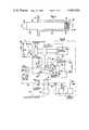
- FIG. 2shows an electrical block diagram in a schematic representation of the reader and its evaluating arrangement by way of one example of embodiment of an optical reading device
- FIG. 3is the schematical representation of a further example of embodiment of a reader whose optical-system part can be switched to the scanning and the transmitting operation, and the schematic circuit representation,
- FIG. 4is the schematical representation of a wand-shaped reader as placed into the compartment of an equipment containing the evaluating arrangement
- FIG. 5shows an electrical block diagram in a schematical representation of the reader and the evaluating arrangement of a further example of embodiment of an optical reading device in which the reader is capable of being placed into a compartment of the equipment containing the evaluating arrangement.
- FIG. 1ashows a reader 1 forming part of an optical reading device, which is led by hand in such a way over a character code 3 deposited on a recording medium 2, that the scanning head 4 arranged at one end of the rod-shaped housing 5 of the reader, is applied to the recording medium and sweeps over the character code.
- the readeris switched to perform the scanning operation.
- a photoreceiver in the scanning head 4through a light-exiting aperture 7 provided for in the scanning head 4, scans the different light reflections caused by the characters of the character code, i.e. scans reflections of the light which is transmitted through the light-exiting aperture and on to the character code by a phototransmitter likewise arranged inside the scanning head 4.
- the character code as shown in FIG. 1ais a bar code consisting of bars and spaces of different widths.
- the data scanned from the character codeare stored in the reader 1 and, thereafter, transmitted to an evaluating circuit via light or sound waves.
- FIG. 1bthe reader as shown in FIG. 1a, is pointed with its end opposite the scanning head, at a photo- or sound-receiver 8 of an evaluating circuit associated with the reader 1, which is arranged in an equipment 9 separated from the reader, e.g., in a video tape recorder, and a pushbutton 10 is depressed
- the data as stored in the reader, and by means of a photo- or sound transmitter 11 arranged at one end of the readerare transmitted via light- or sound-waves 12, in particular via infrared light or ultrasonic waves, to the photo- or sound-receiver 8 forming part of the equipment 9.
- FIG. 2An optical reading device in which the scanned data as stored in the reader 1 are transmitted to an evaluating circuit 13 by means of infrared light waves, is shown in detail in the block diagram of FIG. 2.
- a light-emitting diode (LED) 15which, across a resistor 16 and via a switch 17, is connected to the battery 18 of the reader.
- the emitted light 19is reflected by the bar code, and through the here not particularly shown light exiting aperture of the scanning head of the reader, impinges upon a photodiode 20 serving as a photo-receiver, which converts the light fluctuations into an electric signal.
- This electric signalappears at the output of an amplifier 21 arranged subsequently to the photodiode, as an amplified electric scanning signal 22.
- the bar code 3 schematically shown in FIG. 2has a predetermined raster which is determinative of the different widths of both the bars and the spaces of the bar code, and from which a clock pattern of the bar code may be derived.
- Each sentence of the bar code which is to be scanned in the course of one scanning operationcontains the same number of raster clocks and a checkable arrangement of the bars.
- a pulse shaping and separating circuit 23which is arranged subsequently to the amplifier 21, there is formed from the scanning signal 22 a pulse train 24 corresponding to the bar pattern of the bar code and which appears at the data output 25 of the circuit 23.
- the data pulse train 24is applied via a gate circuit 28 to a first data input D1 of a shift register 29, and the clock pulse train 27 is applied via a further gate circuit 30 to the clock input T of the shift register, and to a counting input 31 of a clock counter 32.
- the shift register 29, the clock counter 32, the gate circuits 28 and 30 together with further gate circuits 33 and 34 and a clock pulse generator 35form part of a storage circuit 36 of the reader, wherein the shift register 29 is the storage device for the data pulse train 24.
- the clock counterproduces at its output 37 a signal by which the gate circuits 28 and 30 are are switched to the non-conducting state at their inhibiting inputs 38 and 39 and by which the gate circuits 33 and 34 are switched to the conducting state.
- the switch 17During the scanning operation it is necessary for the switch 17 to be retained in the switched-on position II by means of the pushbutton key 6.
- a switch 40For transmitting the data pulse train as stored into the shift register 29, to the evaluating circuit 13, a switch 40 is brought by means of the pushbutton key 10 into the switch position II in which it switches the clock generator 35, the gate circuit 34 and a transmitter circuit 41 with a light-emitting diode 42 to the battery 18.
- the clock pulse generator 35thus produces clock pulses which, via the gate circuit 33, are applied to the clock input T of the shift register and serially feed the stored data pulse train at the data output Do out of the shift register and into both the transmitting circuit 41 and a second data input D2 of the shift register.
- the data pulse train 24can be radiated repeatedly by the phototransmitter 42 until the reception thereof is acknowledged, for example, by the evaluating circuit 13.
- a resetting signalis produced in a reset circuit 43 by which the contents of both the shift register 29 and the clock counter 32 are erased.
- the storage circuit 36remains connected to the battery 18 which brings about low current consumption.
- the data pulse trains radiated by the LED 42 of the phototransmitter 41/42 of the reader 1 to the evaluating circuit 13are received by a photodiode 44 of the evaluating circuit 13, amplified in a subsequently arranged amplifier 45, reconditioned in a pulse circuit 46 and stored into a storage circuit 47 of the evaluating circuit for being evaluated.
- the received and reconditioned pulse trainis fed to a test circuit 48 which, in response to a faultless data pulse train, produces at its release output 49 a release signal and, in the event of a faulty pulse train, produces a fault signal at its fault output 50.
- the fault signalis applied to the reset input R of the storage circuit of the evaluating circuit and erases the last either partly or completely stored data pulse train.
- the release signalhowever, in a signal circuit 51 connected to the release output of the test circuit, triggers an acknowledging signal which, by an acknowledging signal transmitter 52, is radiated either as a visual-light or as an audible sound-signal.
- the reader 53as schematically shown by way of example in FIG. 3 has no light or sound transmitter of its own for transmitting the stored data pulse train, but comprises a part 55 of the lens system 56 of the reader arranged displaceably inside the scanning head 54. Moreover, inside the scanning head of the reader 53 there is arranged the phototransmitter 58 containing a light-emitting diode 57, and the photoreceiver 60 containing a photodiode 59, each with a fixed lens 61 and 62.
- the light-emitting diode 57in a first switch position I of a switch 63a, is connected across a resistor 67 and via an operating switch 65 to a battery 66 supplying the circuit of the reader with the necessary operating voltage.
- the displaceable lens system part 55is connected via a mechanical operative connection 67 to the switch 63a, 63b and, in the switch position I thereof, is in a retracted position A in which the lens system 56 images outside the scanning head 54 and directly in front of the light-exiting aperture 68 thereof, a light spot 69, from which the character code to be scanned, as deposited on a recording medium 70 in front of the light-exiting aperture, reflects the light 71 to the photodiode 59 of the phototransmitter 60.
- the scanning signal as produced by the photodiodeis amplified in an amplifier 72 and is reconditioned in a pulse reconditioning circuit 73 for being stored into the subsequently arranged storage circuit 74.
- the storage circuitcontains two control inputs 75 and 76 to which the switch 63bis connected. In the first position I of the switch 63b a signal from a signal source formed by a voltage divider 77 is applied to the input 75, with this signal switching the storage circuit 74 to storage operation.
- the switch 63a, 63bFor radiating the data pulse train as scanned and stored into the storage circuit of the reader 53, the switch 63a, 63b is switched to the second switch position II, and the displaceable part 55 of the lens system 56 is brought into the forward position B, by which the control signal, via the switch 63b, is applied to the control input 76 of the storage circuit 74, thus causing the storage circuit to operate in the readout mode.
- the stored data pulse trainis read out at the data output 79 of the storage circuit serially and, via a driver circuit 80 and the switch 63a, to the LED 57.
- This LED 57in this particular switch position II, radiates the read out data pulse train through the light-exiting aperture 68 to the evaluating circuit which is not particularly shown.
- the lens systemWhen set to position B, the lens system produces a cone of light which is favourable for the radiation purpose.
- FIG. 4shows a rod-shaped code-bar reader 81 positioned in its sleeve-shaped compartment 82 provided for in the housing 83 of an equipment, such as a video tape recorder or radio receiver containing the evaluating circuit necessary for the reader.
- the end of the rod-shaped housing 85 of the reader, lying opposite the scanning head 84is provided with a plug contact device 86 with socket contacts 87 serving as the connector for the circuit of the reader.
- a plug contact device 88with plug contacts 89 serving as the mating contacts of the connector.
- the reader 81contains in its scanning head 84 a light-emitting diode 90 serving as the phototransmitter which, across a resistor 91, is connected to the supply voltage U B of a battery 22 of the reader, and also contains a photodiode 93 for serving as the photoreceiver.
- the scanning signal as produced upon scanning a character code, at the output of the photodiode 93,is amplified in a subsequently arranged amplifier 94, and in a pulse reconditioning circuit 95, there is formed therefrom a data pulse train 24 and a clock pulse train 27, i.e., of the raster clocks of the scanning signal. Both pulse trains are applied via a gate circuit 96 to the data input D1 or to the clock input T of a shift register 97 serving as the first storage circuit into which the scanned pulse train 24 is stored.
- the pulses of the clock pulse trainare counted into a clock counter 98 which, at its output 99, produces an output signal as soon as a predetermined number of clock pulses has been counted into the clock counter, with this signal serving to switch the gate circuit 96 into the nonconducting state.
- the data pulse train 24moreover, behind the gate circuit 96, is applied to the input of a test circuit 100 which, in the event of a faulty data pulse train, produces a fault signal at a fault output 101 and, in the event of a faultless data input train, produces a release signal at a release output 102.
- the fault output 101is connected via a decoupling OR circuit 103 to the reset inputs R of the clock counter and of the shift register and, in the event of a faulty data pulse train, erases the contents of the shift register 97 and of the clock counter 98, so that the just scanned word of the character code must be scanned again and stored into the shift register 97.
- both the output signal of the clock counter 99 and the release signal of the test circuit 100act upon the control input 105 of a restoring circuit 106 thus tripping a restoring process by which the data pulse train as stored in the shift register 97 is restored into a second storage circuit 107.
- the restoring circuitat one reset output 108, produces a reset signal by which the shift register 97 and the clock counter 99 are reset to normal.
- the release signalproduces in a gate circuit 109 connected to the release output 102 of the test circuit, an acknowledgment signal radiated by the sound source 110. Thereafter, a new word in character code can be scanned by the reader on the recording medium.
- the second storage circuit 107has a capacity suitable for storing several data pulse trains 24, so that several words can be scanned successively.
- the words or sentences in character code capable of being read in the course of one scan cycleeach have the same predetermined number of raster elements.
- the readerFor effecting the readout of the information stored in the second storage circuit, the reader is inserted into its compartment in an equipment containing the associated evaluating circuit, so that the electric connecting contacts 87a through 87d of the circuit of the reader 81 come into electrical contact with the associated opposite contacts 89a through 89d of the evaluating circuit 111.
- the readervia a switch 112 actuated by it, switches on a clock pulse generator 113 of the evaluating circuit, and the clock pulses thereof serially read out the contents of the second storage circuit 107 of the reader, and transfer the read out information into a storage circuit 114 of the evaluating circuit for further processing.
- the battery 22is of the rechargeable type which, when the reader is inserted in its compartment 82, is connected to a charging circuit 115 of the evaluating circuit via the contacts 87c, 87d and 89c, 89d, for being recharged in this way and maintaining its charge when the reader is replaced into its compartment.
- a switch 116 of the readeractuated inside the receiving compartment, the diodes 90 and 93 can be switched away from the battery when in this particular state.
Landscapes
- Physics & Mathematics (AREA)
- Engineering & Computer Science (AREA)
- Electromagnetism (AREA)
- Artificial Intelligence (AREA)
- Toxicology (AREA)
- General Health & Medical Sciences (AREA)
- Health & Medical Sciences (AREA)
- Computer Vision & Pattern Recognition (AREA)
- General Physics & Mathematics (AREA)
- Theoretical Computer Science (AREA)
- Character Discrimination (AREA)
- Character Input (AREA)
- Input From Keyboards Or The Like (AREA)
Abstract
Description
Claims (9)
Applications Claiming Priority (2)
| Application Number | Priority Date | Filing Date | Title |
|---|---|---|---|
| DE3109286 | 1981-03-11 | ||
| DE3109286ADE3109286C2 (en) | 1981-03-11 | 1981-03-11 | Optical reading device for manual scanning and for evaluating optically readable character code fonts |
Publications (1)
| Publication Number | Publication Date |
|---|---|
| US4465926Atrue US4465926A (en) | 1984-08-14 |
Family
ID=6126929
Family Applications (1)
| Application Number | Title | Priority Date | Filing Date |
|---|---|---|---|
| US06/355,016Expired - LifetimeUS4465926A (en) | 1981-03-11 | 1982-03-05 | Optical reading device for the manual optical scanning and for evaluating optically readable character codes |
Country Status (3)
| Country | Link |
|---|---|
| US (1) | US4465926A (en) |
| JP (1) | JPS57209571A (en) |
| DE (1) | DE3109286C2 (en) |
Cited By (44)
| Publication number | Priority date | Publication date | Assignee | Title |
|---|---|---|---|---|
| US4673804A (en)* | 1984-03-09 | 1987-06-16 | Elettronica San Giorgio - Elsag S.P.A. | Electronic graphic detecting head |
| US4743744A (en)* | 1985-07-09 | 1988-05-10 | Alps Electric Co., Ltd. | Bar code reader |
| US4801786A (en)* | 1984-05-25 | 1989-01-31 | Anatoli Stobbe | Checking system and method for verifying checking stations in a monitoring system |
| US4816659A (en)* | 1987-10-13 | 1989-03-28 | Control Module Inc. | Bar code reader head |
| WO1989004016A1 (en)* | 1987-10-22 | 1989-05-05 | Zengrange Limited | Data collection |
| US4841132A (en)* | 1986-07-21 | 1989-06-20 | Matsushita Electric Industrial Co., Ltd. | Program recording scheduling apparatus using an optical reader |
| US4899370A (en)* | 1987-06-12 | 1990-02-06 | Matsushita Electric Industrial Co., Ltd. | Remote control apparatus for electronic equipment |
| US4945216A (en)* | 1985-11-06 | 1990-07-31 | Sharp Kabushiki Kaisha | Wireless bar code reader |
| US5055660A (en)* | 1988-06-16 | 1991-10-08 | Avicom International, Inc. | Portable transaction monitoring unit for transaction monitoring and security control systems |
| US5132523A (en)* | 1990-12-10 | 1992-07-21 | Ncr Corporation | Dual mode optical scanning system |
| US5189291A (en)* | 1989-05-01 | 1993-02-23 | Symbol Technologies, Inc. | Bar code reader operable as remote scanner or with fixed terminal |
| US5446518A (en)* | 1989-05-29 | 1995-08-29 | Canon Kabushiki Kaisha | Automatic exposure control apparatus |
| US5471043A (en)* | 1992-10-02 | 1995-11-28 | Kronos Incorporated | Electro-optic barcode reader |
| US5483052A (en)* | 1993-12-07 | 1996-01-09 | Smith, Iii; Herbert J. | System for reading, storing and using bar-encoded data from a coded business card or other printed material |
| US5747786A (en)* | 1989-04-14 | 1998-05-05 | Norand Corporation | Communication module for a data capture system |
| US5930767A (en)* | 1997-05-28 | 1999-07-27 | Motorola, Inc. | Transaction methods systems and devices |
| US6119944A (en)* | 1997-02-03 | 2000-09-19 | Symbol Technologies, Inc. | Down-loadable hand-held optical reader |
| US6145746A (en)* | 1991-11-04 | 2000-11-14 | Symbol Technologies, Inc. | Portable optical scanning and pointing systems |
| US6300880B1 (en)* | 1996-01-16 | 2001-10-09 | Philips Electronics North America Corp. | Multichannel audio distribution system having portable receivers |
| WO2001084476A1 (en)* | 2000-05-03 | 2001-11-08 | Boonphet Meksavan | Method, system, and apparatus for processing barcode data |
| US20020104886A1 (en)* | 1998-12-03 | 2002-08-08 | Metrologic Instruments, Inc. | Automatically-activated hand-supportable laser scanning bar code symbol reading system with omnidirectional and unidirectional scanning modes in addition to a data transmission activation switch |
| US6595420B1 (en) | 1990-09-10 | 2003-07-22 | Metrologic Instruments, Inc. | Automatically-activated body-wearable laser scanning bar code symbol reading system having data-transmission activation switch |
| US6607133B2 (en)* | 1990-09-10 | 2003-08-19 | Metrologic Instruments, Inc. | Automatically-activated hand-supportable laser scanning bar code symbol reading system with data transmission activation switch |
| US20030222146A1 (en)* | 1998-12-03 | 2003-12-04 | Metrologic Instruments, Inc. | Automatically-activated hand-supportable multi-mode laser scanning bar code symbol reading system |
| US6691919B1 (en)* | 1998-03-24 | 2004-02-17 | Symbol Technologies, Inc. | Integrated bar code scanner and communications module |
| US20040036774A1 (en)* | 2002-08-23 | 2004-02-26 | Nichols James F. | Digital camera/computer synchronization method |
| US20040173684A1 (en)* | 1998-12-03 | 2004-09-09 | Metrologic Instruments, Inc. | Automatically-activated hand-supportable omni-directional laser scanning bar code symbol reader having a user-selectable linear scanning menu-reading mode supported by a stroboscopically-pulsed omni-directional laser scanning pattern for improved bar code symbol navigation and alignment during menu-reading operations |
| US20040197046A1 (en)* | 2003-04-02 | 2004-10-07 | Drost Robert J. | Optical communication between face-to-face semiconductor chips |
| US20040206825A1 (en)* | 1998-12-03 | 2004-10-21 | Metrologic Instruments, Inc. | Wireless bar code symbol driven portable data terminal ( PDT) system adapted for single handed operation |
| US6866196B1 (en) | 1994-05-25 | 2005-03-15 | Spencer A. Rathus | Method and apparatus for accessing electronic data via a familiar printed medium |
| US20050127185A1 (en)* | 1990-09-17 | 2005-06-16 | Wilz David M.Sr. | Automatically-activated hand-supportable laser scanning bar code symbol reading system with data transmission activation switch |
| US7074509B2 (en) | 2001-11-13 | 2006-07-11 | Eldat Communication Ltd. | Hydrogen generators for fuel cells |
| US7111786B2 (en) | 1998-12-03 | 2006-09-26 | Metrologic Instruments, Inc. | Automatically-activated wireless hand-supportable laser scanning bar code symbol reading system with data transmission activation switch and automatic communication range dependent control |
| USD542796S1 (en)* | 2005-06-21 | 2007-05-15 | Idt Electronic Products Limited | Code reader |
| EP1631123A3 (en)* | 2004-08-26 | 2007-08-29 | Samsung Electronics Co., Ltd. | Microwave oven with bar code scanner |
| US20110055045A1 (en)* | 2009-09-02 | 2011-03-03 | Caine Smith | Method and system of displaying, managing and selling images in an event photography environment |
| US20110066494A1 (en)* | 2009-09-02 | 2011-03-17 | Caine Smith | Method and system of displaying, managing and selling images in an event photography environment |
| US8261993B2 (en) | 1994-05-25 | 2012-09-11 | Marshall Feature Recognition, Llc | Method and apparatus for accessing electronic data via a familiar printed medium |
| US8261994B2 (en) | 1994-05-25 | 2012-09-11 | Marshall Feature Recognition, Llc | Method and apparatus for accessing electronic data via a familiar printed medium |
| USD669083S1 (en)* | 2010-11-16 | 2012-10-16 | Tru-Test Limited | Wireless tag reader |
| US8910876B2 (en) | 1994-05-25 | 2014-12-16 | Marshall Feature Recognition, Llc | Method and apparatus for accessing electronic data via a familiar printed medium |
| USD724592S1 (en)* | 2014-02-21 | 2015-03-17 | Amazon Technologies, Inc. | Scanner device |
| DE202017001909U1 (en) | 2017-04-04 | 2017-05-16 | Semen Zaitchik | Device for improving the mental and physical well-being by optimizing the ratios of biological rhythms with the aid of biofeedback |
| USD797107S1 (en)* | 2015-07-02 | 2017-09-12 | Datalogic Ip Tech S.R.L. | Portable terminal |
Families Citing this family (16)
| Publication number | Priority date | Publication date | Assignee | Title |
|---|---|---|---|---|
| DE3243711A1 (en)* | 1982-11-25 | 1984-05-30 | Preh Elektro Feinmechanik | Stylus for a contact panel |
| DE3365157D1 (en)* | 1982-11-25 | 1986-09-11 | Preh Elektro Feinmechanik | Apparatus for detecting an x-y position |
| US4638312A (en)* | 1985-10-25 | 1987-01-20 | Ncr Corporation | Order entry system including an interactive menu display |
| JPH0342510Y2 (en)* | 1985-11-12 | 1991-09-05 | ||
| JPS6355681A (en)* | 1986-08-26 | 1988-03-10 | Matsushita Electric Ind Co Ltd | barcode reader |
| JPS63146185A (en)* | 1986-12-10 | 1988-06-18 | Matsushita Electric Ind Co Ltd | barcode reader |
| DE8804625U1 (en)* | 1988-04-08 | 1988-06-09 | Winter, Hans-Joachim, 2000 Hamburg | Drawing machine with drawing pen |
| DE3814728A1 (en)* | 1988-04-30 | 1989-11-09 | Telefonbau & Normalzeit Gmbh | Cordless telephone system |
| DE3816800A1 (en)* | 1988-05-17 | 1989-11-30 | Zinser Textilmaschinen Gmbh | METHOD AND DEVICE FOR ASSIGNING YARN AND / OR MACHINE-RELATED DATA TO SPOOL SLEEVES OF SPINNING MACHINES |
| JP2667503B2 (en)* | 1989-04-13 | 1997-10-27 | パイオニア株式会社 | Sound equipment with detachable operation body |
| JPH0397082A (en)* | 1989-09-08 | 1991-04-23 | Tokyo Electric Co Ltd | label issuing device |
| JP2772691B2 (en)* | 1989-12-19 | 1998-07-02 | 松下電器産業株式会社 | Barcode signal transfer device |
| JPH04165678A (en)* | 1990-10-30 | 1992-06-11 | Nippon Motoroola Kk | Mesh gate type MOS transistor |
| DE4129571C2 (en)* | 1991-09-06 | 2002-02-07 | Clemens Croy | Device for programming recording devices |
| DE9113324U1 (en)* | 1991-10-26 | 1992-02-13 | Fasolo, Gianni, 3575 Kirchhain | Mobile wireless barcode reader for cash register systems and data processing systems |
| FR2700033B1 (en)* | 1992-12-30 | 1995-04-07 | Inglese Jean Marc | Method for remote and wireless transfer of data from a data acquisition module to a data storage station and device for implementing this method. |
Citations (7)
| Publication number | Priority date | Publication date | Assignee | Title |
|---|---|---|---|---|
| US3826900A (en)* | 1972-10-13 | 1974-07-30 | Ncr | Cordless scanning probe |
| JPS5263623A (en)* | 1975-11-19 | 1977-05-26 | Matsushita Electric Ind Co Ltd | Data entry machine |
| US4120452A (en)* | 1975-08-14 | 1978-10-17 | Matsushita Electric Industrial Co., Ltd. | Automatic vending system |
| US4179064A (en)* | 1976-03-18 | 1979-12-18 | Matsushita Electric Industrial Co., Ltd. | Vending apparatus |
| US4224666A (en)* | 1977-04-27 | 1980-09-23 | Compagnie Internationale Pour L'informatique Cii-Honeywell Bull | Data processing system which protects the secrecy of confidential data |
| US4297569A (en)* | 1979-06-28 | 1981-10-27 | Datakey, Inc. | Microelectronic memory key with receptacle and systems therefor |
| US4418277A (en)* | 1980-11-19 | 1983-11-29 | Hartmut Tremmel | Apparatus for collecting, transmitting and processing data stored in code, preferably in bar code |
Family Cites Families (3)
| Publication number | Priority date | Publication date | Assignee | Title |
|---|---|---|---|---|
| DE2338773A1 (en)* | 1973-07-31 | 1975-02-13 | Siemens Ag | Label reader for inventory checking system - optical reader shaped to fit into socket for data transfer |
| JPS51123023A (en)* | 1975-04-21 | 1976-10-27 | Tekunirabo:Kk | The detecting method of ready condition |
| JPS5271435U (en)* | 1975-11-21 | 1977-05-27 |
- 1981
- 1981-03-11DEDE3109286Apatent/DE3109286C2/ennot_activeExpired
- 1982
- 1982-03-05USUS06/355,016patent/US4465926A/ennot_activeExpired - Lifetime
- 1982-03-11JPJP57037340Apatent/JPS57209571A/enactiveGranted
Patent Citations (7)
| Publication number | Priority date | Publication date | Assignee | Title |
|---|---|---|---|---|
| US3826900A (en)* | 1972-10-13 | 1974-07-30 | Ncr | Cordless scanning probe |
| US4120452A (en)* | 1975-08-14 | 1978-10-17 | Matsushita Electric Industrial Co., Ltd. | Automatic vending system |
| JPS5263623A (en)* | 1975-11-19 | 1977-05-26 | Matsushita Electric Ind Co Ltd | Data entry machine |
| US4179064A (en)* | 1976-03-18 | 1979-12-18 | Matsushita Electric Industrial Co., Ltd. | Vending apparatus |
| US4224666A (en)* | 1977-04-27 | 1980-09-23 | Compagnie Internationale Pour L'informatique Cii-Honeywell Bull | Data processing system which protects the secrecy of confidential data |
| US4297569A (en)* | 1979-06-28 | 1981-10-27 | Datakey, Inc. | Microelectronic memory key with receptacle and systems therefor |
| US4418277A (en)* | 1980-11-19 | 1983-11-29 | Hartmut Tremmel | Apparatus for collecting, transmitting and processing data stored in code, preferably in bar code |
Cited By (93)
| Publication number | Priority date | Publication date | Assignee | Title |
|---|---|---|---|---|
| US4673804A (en)* | 1984-03-09 | 1987-06-16 | Elettronica San Giorgio - Elsag S.P.A. | Electronic graphic detecting head |
| US4801786A (en)* | 1984-05-25 | 1989-01-31 | Anatoli Stobbe | Checking system and method for verifying checking stations in a monitoring system |
| US4743744A (en)* | 1985-07-09 | 1988-05-10 | Alps Electric Co., Ltd. | Bar code reader |
| US4945216A (en)* | 1985-11-06 | 1990-07-31 | Sharp Kabushiki Kaisha | Wireless bar code reader |
| US4841132A (en)* | 1986-07-21 | 1989-06-20 | Matsushita Electric Industrial Co., Ltd. | Program recording scheduling apparatus using an optical reader |
| US4899370A (en)* | 1987-06-12 | 1990-02-06 | Matsushita Electric Industrial Co., Ltd. | Remote control apparatus for electronic equipment |
| US4816659A (en)* | 1987-10-13 | 1989-03-28 | Control Module Inc. | Bar code reader head |
| EP0312298A3 (en)* | 1987-10-13 | 1990-07-25 | Control Module, Inc. | Bar code reader head |
| WO1989004016A1 (en)* | 1987-10-22 | 1989-05-05 | Zengrange Limited | Data collection |
| US5055660A (en)* | 1988-06-16 | 1991-10-08 | Avicom International, Inc. | Portable transaction monitoring unit for transaction monitoring and security control systems |
| US5747786A (en)* | 1989-04-14 | 1998-05-05 | Norand Corporation | Communication module for a data capture system |
| US5189291A (en)* | 1989-05-01 | 1993-02-23 | Symbol Technologies, Inc. | Bar code reader operable as remote scanner or with fixed terminal |
| US5446518A (en)* | 1989-05-29 | 1995-08-29 | Canon Kabushiki Kaisha | Automatic exposure control apparatus |
| US6637659B2 (en)* | 1990-09-10 | 2003-10-28 | Metrologic Instruments, Inc. | Automatically-activated hand-supportable omni-directional laser scanning bar code symbol reading system with data transmission activation switch |
| US20040089721A1 (en)* | 1990-09-10 | 2004-05-13 | Wilz David M. | Automatically-activated hand-supportable laser scanning bar code symbol reading system with data transmission activation switch |
| US6783075B2 (en) | 1990-09-10 | 2004-08-31 | Metrologic Instruments, Inc. | Portable hand-supportable data terminal with automatically-activated laser scanning bar code symbol reader integrated therein |
| US6772949B2 (en) | 1990-09-10 | 2004-08-10 | Metrologic Instruments, Inc. | Portable hand-supportable data terminal with automatically-activated laser scanning bar code symbol reader integrated therein |
| US7252238B2 (en) | 1990-09-10 | 2007-08-07 | Metrologic Instruments, Inc. | Automatically-activated hand-supportable laser scanning bar code symbol reading system with data transmission activation switch |
| US6607133B2 (en)* | 1990-09-10 | 2003-08-19 | Metrologic Instruments, Inc. | Automatically-activated hand-supportable laser scanning bar code symbol reading system with data transmission activation switch |
| US6595420B1 (en) | 1990-09-10 | 2003-07-22 | Metrologic Instruments, Inc. | Automatically-activated body-wearable laser scanning bar code symbol reading system having data-transmission activation switch |
| US20080041962A1 (en)* | 1990-09-17 | 2008-02-21 | Metrologic Instruments Inc. | Automatically-activated hand-supportable laser scanning bar code symbol reading system with data transmission activation switch |
| US7611063B2 (en) | 1990-09-17 | 2009-11-03 | Metrologic Instruments, Inc. | Automatically-activated code symbol reading system |
| US7156310B2 (en)* | 1990-09-17 | 2007-01-02 | Metrologic Instruments, Inc. | Automatically-activated hand-supportable laser scanning bar code symbol reading system with data transmission activation switch |
| US20050127185A1 (en)* | 1990-09-17 | 2005-06-16 | Wilz David M.Sr. | Automatically-activated hand-supportable laser scanning bar code symbol reading system with data transmission activation switch |
| US5132523A (en)* | 1990-12-10 | 1992-07-21 | Ncr Corporation | Dual mode optical scanning system |
| US6145746A (en)* | 1991-11-04 | 2000-11-14 | Symbol Technologies, Inc. | Portable optical scanning and pointing systems |
| US5471043A (en)* | 1992-10-02 | 1995-11-28 | Kronos Incorporated | Electro-optic barcode reader |
| US5483052A (en)* | 1993-12-07 | 1996-01-09 | Smith, Iii; Herbert J. | System for reading, storing and using bar-encoded data from a coded business card or other printed material |
| US6866196B1 (en) | 1994-05-25 | 2005-03-15 | Spencer A. Rathus | Method and apparatus for accessing electronic data via a familiar printed medium |
| US8485445B2 (en) | 1994-05-25 | 2013-07-16 | Marshall Feature Recognition, Llc | Method and apparatus for accessing electronic data via a familiar printed medium |
| US8261993B2 (en) | 1994-05-25 | 2012-09-11 | Marshall Feature Recognition, Llc | Method and apparatus for accessing electronic data via a familiar printed medium |
| US8261994B2 (en) | 1994-05-25 | 2012-09-11 | Marshall Feature Recognition, Llc | Method and apparatus for accessing electronic data via a familiar printed medium |
| US8910876B2 (en) | 1994-05-25 | 2014-12-16 | Marshall Feature Recognition, Llc | Method and apparatus for accessing electronic data via a familiar printed medium |
| US6300880B1 (en)* | 1996-01-16 | 2001-10-09 | Philips Electronics North America Corp. | Multichannel audio distribution system having portable receivers |
| US6119944A (en)* | 1997-02-03 | 2000-09-19 | Symbol Technologies, Inc. | Down-loadable hand-held optical reader |
| US5930767A (en)* | 1997-05-28 | 1999-07-27 | Motorola, Inc. | Transaction methods systems and devices |
| US6976626B2 (en) | 1997-09-16 | 2005-12-20 | Metrologic Instruments, Inc. | Wireless bar code symbol driven portable data terminal (PDT) system adapted for single handed operation |
| US6691919B1 (en)* | 1998-03-24 | 2004-02-17 | Symbol Technologies, Inc. | Integrated bar code scanner and communications module |
| US7325740B2 (en) | 1998-12-03 | 2008-02-05 | Metrologic Instruments, Inc. | Automatically-activated laser scanning 2D bar code symbol reading system employing a visible linear-type laser scanning pattern and an audible feedback signal during scan data capturing and buffering operations |
| US7121468B2 (en) | 1998-12-03 | 2006-10-17 | Metrologic Instruments, Inc. | Method of developing an application program for running on a wireless portable data terminal (PDT) |
| US20040251307A1 (en)* | 1998-12-03 | 2004-12-16 | Metrologic Instruments, Inc. | Automatically-activated hand-supportable 2-D bar code symbol reading system employing a linear laser scanning pattern generator, an automatic bar code symbol data detector, audible data capture feedback generator, and a manually-activated data transmission activation switch |
| US20050121523A1 (en)* | 1998-12-03 | 2005-06-09 | Metrologic Instruments, Inc. | Wireless laser scanning bar code symbol reading system employing a low-battery protection circuit, vibrational alarm and sleep mode of operation |
| US6905071B2 (en)* | 1998-12-03 | 2005-06-14 | Metrologic Instruments, Inc. | Automatically-activated hand-supportable multi-mode laser scanning bar code symbol reading system |
| US20040206825A1 (en)* | 1998-12-03 | 2004-10-21 | Metrologic Instruments, Inc. | Wireless bar code symbol driven portable data terminal ( PDT) system adapted for single handed operation |
| US20050199728A1 (en)* | 1998-12-03 | 2005-09-15 | Mark Schmidt | Wireless laser scanning bar code symbol reading system, wherein the RF-based transceiver chipsets within the wireless hand-supportable unit and base station thereof are automatically deactivated and said RF data communication link therebetween terminated when said system enters its power-saving sleep mode, and reactivated and re-eastablished when re-entering its operational mode |
| US20050199727A1 (en)* | 1998-12-03 | 2005-09-15 | Mark Schmidt | Wireless bar code symbol reading system capable of automatically collecting and storing symbol character data when hand-supportable unit is operated outside of its RF data communication range, and automatically transmitting stored symbol character data when the hand-supportable unit is operated within its RF data communication range |
| US20050199726A1 (en)* | 1998-12-03 | 2005-09-15 | Metrologic Instruments, Inc. | Automatically-activated laser scanning 2D bar code symbol reading system |
| US20050211782A1 (en)* | 1998-12-03 | 2005-09-29 | William Martin | Automatically-activated hand-supportable laser scanning bar code symbol reading system with omnidirectional and unidirectional scanning modes in addition to a data transmission activation switch |
| US20050274810A1 (en)* | 1998-12-03 | 2005-12-15 | Metrologic Instruments, Inc. | Wireless bar code symbol reading system employing a base station with a cradle having a hinged support hooks for enabling vertical and horizontal installations |
| US7686225B2 (en) | 1998-12-03 | 2010-03-30 | Metrologic Instruments, Inc. | Wireless code symbol reading system with automatic communication range dependent control |
| US7007849B2 (en) | 1998-12-03 | 2006-03-07 | Metrologic Instruments, Inc. | Automatically-activated hand-supportable 2-d bar code symbol reading system employing a linear laser scanning pattern generator, an automatic bar code symbol data detector, audible data capture feedback generator, and a manually-activated data transmission activation switch |
| US7028904B2 (en) | 1998-12-03 | 2006-04-18 | Metrologic Instruments, Inc. | Wireless bar code symbol reading system capable of automatically collecting and storing symbol character data when hand-supportable unit is operated outside of its rf data communication range, and automatically transmitting stored symbol character data when the hand-supportable unit is operated within its rf data communication range |
| US7048192B2 (en) | 1998-12-03 | 2006-05-23 | Metrologic Instruments, Inc. | Wireless bar code symbol reading system employing a base station with a cradle having a hinged support hooks for enabling vertical and horizontal installations |
| US7523867B2 (en) | 1998-12-03 | 2009-04-28 | Metrologic Instruments, Inc. | Automatically-activated hand-supportable laser scanning bar code symbol reading system with omnidirectional and unidirectional scanning modes in addition to a data transmission activation switch |
| US20060169782A1 (en)* | 1998-12-03 | 2006-08-03 | Metrologic Instruments, Inc. | Automatically-activated wireless laser scanning 2D bar code symbol reading system capable of automatically transmitting stored symbol character data when the hand-supportable unit is operated within its RF data communication range and automatically collecting and storing symbol character data when the hand-supportable unit is operated outside of its RF data communication range |
| US7097105B2 (en) | 1998-12-03 | 2006-08-29 | Metrologic Instruments, Inc. | Automatically-activated hand-supportable omni-directional laser scanning bar code symbol reader having a user-selectable linear scanning menu-reading mode supported by a stroboscopically-pulsed omni-directional laser scanning pattern for improved bar code symbol navigation and alignment during menu-reading operations |
| US7111786B2 (en) | 1998-12-03 | 2006-09-26 | Metrologic Instruments, Inc. | Automatically-activated wireless hand-supportable laser scanning bar code symbol reading system with data transmission activation switch and automatic communication range dependent control |
| US7934659B2 (en) | 1998-12-03 | 2011-05-03 | Metrologic Instruments, Inc. | Wireless bar code symbol driven portable data terminal (PDT) system for running application programs on an operating system emulated on a virtual machine |
| US7137561B2 (en) | 1998-12-03 | 2006-11-21 | Metrologic Instruments, Inc. | Wireless laser scanning bar code symbol reading system employing a low-battery protection circuit, vibrational alarm and sleep mode of operation |
| US20040173684A1 (en)* | 1998-12-03 | 2004-09-09 | Metrologic Instruments, Inc. | Automatically-activated hand-supportable omni-directional laser scanning bar code symbol reader having a user-selectable linear scanning menu-reading mode supported by a stroboscopically-pulsed omni-directional laser scanning pattern for improved bar code symbol navigation and alignment during menu-reading operations |
| US7172126B2 (en) | 1998-12-03 | 2007-02-06 | Metrologic Instruments, Inc. | Wireless automatic laser scanning bar code symbol reading system, wherein the RF-based transceiver chipsets within the wireless hand-supportable unit and base station thereof are automatically deactivated and said RF data communication link therebetween terminated when said system enters its power-saving sleep mode, and reactivated and re-established when re-entering its operational mode |
| US20070090192A1 (en)* | 1998-12-03 | 2007-04-26 | Metrologic Intruments, Inc. | Wireless bar code symbol driven portable data terminal (PDT) system for running application programs on an operating system emulated on a virtual machine |
| US20020104886A1 (en)* | 1998-12-03 | 2002-08-08 | Metrologic Instruments, Inc. | Automatically-activated hand-supportable laser scanning bar code symbol reading system with omnidirectional and unidirectional scanning modes in addition to a data transmission activation switch |
| US7464878B2 (en) | 1998-12-03 | 2008-12-16 | Metrologic Instruments, Inc. | Automatically-activated wireless hand-supportable laser scanning bar code symbol reading system with automatic communication range dependent control |
| US6857572B2 (en)* | 1998-12-03 | 2005-02-22 | Metrologic Instruments, Inc. | Automatically-activated hand-supportable laser scanning bar code symbol reading system with omnidirectional and unidirectional scanning modes in addition to a data transmission activation switch |
| US20080128512A1 (en)* | 1998-12-03 | 2008-06-05 | Metrologic Instruments, Inc. | Wireless hand-supportable code symbol reading system with automatic communication range dependent control |
| US7278578B2 (en) | 1998-12-03 | 2007-10-09 | Metrologic Instruments, Inc. | Automatically-activated wireless laser scanning 2D bar code symbol reading system capable of automatically transmitting stored symbol character data when the hand-supportable unit is operated within its RF data communication range and automatically collecting and storing symbol character data when the hand-supportable unit is operated outside of its RF data communication range |
| US7281663B2 (en) | 1998-12-03 | 2007-10-16 | Metrologic Instruments, Inc. | Wireless bar code symbol reading system having hand-supportable unit and remote base station |
| US20040016812A1 (en)* | 1998-12-03 | 2004-01-29 | Metrologic Instruments, Inc. | Wireless bar code symbol reading system capable of automatically collecting and storing symbol character data when hand-supportable unit is operated outside of its RF data communication range, and automatically transmitting stored symbol character data when the hand-supportable unit is operated within its RF data communication range |
| US20030222146A1 (en)* | 1998-12-03 | 2003-12-04 | Metrologic Instruments, Inc. | Automatically-activated hand-supportable multi-mode laser scanning bar code symbol reading system |
| US6547146B1 (en)* | 2000-05-03 | 2003-04-15 | Ipilot, Inc. | Method, system and apparatus for processing barcode data |
| US6581838B1 (en) | 2000-05-03 | 2003-06-24 | Ipilot, Inc. | Optical scanner head for processing barcode data and method of manufacture |
| WO2001084476A1 (en)* | 2000-05-03 | 2001-11-08 | Boonphet Meksavan | Method, system, and apparatus for processing barcode data |
| WO2003042904A1 (en)* | 2001-11-13 | 2003-05-22 | Metrologic Instruments, Inc. | Automatically-activated hand-supportable multi-mode laser scanning bar code symbol reading system |
| US7431215B2 (en) | 2001-11-13 | 2008-10-07 | Metrologic Instruments, Inc. | Automatically-activated hand-supportable omni-directional laser scanning bar code symbol reader having a user-selectable linear scanning menu-reading mode supported by a omni-directional laser scanning pattern having temporally varying intensity characteristics for improved bar code symbol navigation and alignment during menu-reading operations |
| US20070114287A1 (en)* | 2001-11-13 | 2007-05-24 | Wilz David M Sr | Automatically-activated hand-supportable omni-directional laser scanning bar code symbol reader having a user-selectable linear scanning menu-reading mode supported by a omni-directional laser scanning pattern having temporally varying intensity characteristics for improved bar code symbol navigation and alignment during menu-reading operations |
| US7074509B2 (en) | 2001-11-13 | 2006-07-11 | Eldat Communication Ltd. | Hydrogen generators for fuel cells |
| US8071242B2 (en) | 2001-11-13 | 2011-12-06 | Eldat Communication Ltd. | Hydrogen generators for fuel cells |
| US20040036774A1 (en)* | 2002-08-23 | 2004-02-26 | Nichols James F. | Digital camera/computer synchronization method |
| US7430003B2 (en) | 2002-08-23 | 2008-09-30 | Candid Color Systems, Inc. | Digital camera/computer synchronization method |
| US20040197046A1 (en)* | 2003-04-02 | 2004-10-07 | Drost Robert J. | Optical communication between face-to-face semiconductor chips |
| EP1631123A3 (en)* | 2004-08-26 | 2007-08-29 | Samsung Electronics Co., Ltd. | Microwave oven with bar code scanner |
| USD542796S1 (en)* | 2005-06-21 | 2007-05-15 | Idt Electronic Products Limited | Code reader |
| US8392268B2 (en) | 2009-09-02 | 2013-03-05 | Image Holdings | Method and system of displaying, managing and selling images in an event photography environment |
| US8332281B2 (en) | 2009-09-02 | 2012-12-11 | Image Holdings | Method of displaying, managing and selling images in an event photography environment |
| US20110066494A1 (en)* | 2009-09-02 | 2011-03-17 | Caine Smith | Method and system of displaying, managing and selling images in an event photography environment |
| US20110055045A1 (en)* | 2009-09-02 | 2011-03-03 | Caine Smith | Method and system of displaying, managing and selling images in an event photography environment |
| USD669083S1 (en)* | 2010-11-16 | 2012-10-16 | Tru-Test Limited | Wireless tag reader |
| USD724592S1 (en)* | 2014-02-21 | 2015-03-17 | Amazon Technologies, Inc. | Scanner device |
| USD797107S1 (en)* | 2015-07-02 | 2017-09-12 | Datalogic Ip Tech S.R.L. | Portable terminal |
| USD817331S1 (en) | 2015-07-02 | 2018-05-08 | Datalogic Ip Tech S.R.L. | Portable terminal |
| USD836639S1 (en) | 2015-07-02 | 2018-12-25 | Datalogic Ip Tech S.R.L. | Portable terminal |
| DE202017001909U1 (en) | 2017-04-04 | 2017-05-16 | Semen Zaitchik | Device for improving the mental and physical well-being by optimizing the ratios of biological rhythms with the aid of biofeedback |
Also Published As
| Publication number | Publication date |
|---|---|
| DE3109286A1 (en) | 1982-09-23 |
| JPH0226264B2 (en) | 1990-06-08 |
| DE3109286C2 (en) | 1985-02-07 |
| JPS57209571A (en) | 1982-12-22 |
Similar Documents
| Publication | Publication Date | Title |
|---|---|---|
| US4465926A (en) | Optical reading device for the manual optical scanning and for evaluating optically readable character codes | |
| US4999622A (en) | Remote commander having a ROM read-out pre-programmed codes therefrom | |
| US5945660A (en) | Communication system for wireless bar code reader | |
| US4471218A (en) | Self-contained, portable data entry terminal | |
| EP0124331B1 (en) | Remote control transmitter arrangement for one or more television devices | |
| US4423319A (en) | Communication link | |
| US8004389B1 (en) | Relaying key code signals through a remote control device | |
| KR920002229B1 (en) | Reconfigurable remote control transmitter | |
| US6531964B1 (en) | Passive remote control system | |
| EP0595305A1 (en) | IC card reader | |
| CA1304787C (en) | Radio pager having a light-emitting diode for providing visual alarm and signal transmission | |
| US5822098A (en) | Device and method of communication by infrared radiation between a user and a remotely controllable apparatus | |
| RU2002123181A (en) | PORTABLE INFORMATION TERMINAL, DIGITAL CAMERA FOR PORTABLE INFORMATION TERMINAL AND SYSTEM CONSISTING OF PORTABLE INFORMATION TERMINAL AND DIGITAL CAMERA | |
| JPS6193759A (en) | Manufacture of electric apparatus | |
| GB2183070A (en) | Bar-code reader | |
| US3828128A (en) | Manual input device for data-processing system and the like | |
| CN112181183A (en) | Stylus pen, electronic device, control method, control device, and readable storage medium | |
| US6530524B1 (en) | Portable electronic apparatus having a scanner and a data transmitter | |
| JPH07112301B2 (en) | General-purpose remote control system | |
| LT3717B (en) | Autonomous pulse reading and recording system | |
| KR200240928Y1 (en) | Wireless barcode reader | |
| US5001780A (en) | Optical communication adapter with projector | |
| JPS6449367A (en) | Data communication device | |
| JPH06105377A (en) | Remote control system | |
| JPH0380380A (en) | Bar code reader |
Legal Events
| Date | Code | Title | Description |
|---|---|---|---|
| AS | Assignment | Owner name:INTERNATIONAL STANDARD ELECTRIC CORPORATION; 320 P Free format text:ASSIGNMENT OF ASSIGNORS INTEREST.;ASSIGNORS:APITZ, SIEGFRIED;NONNENMANN, ROLF;REEL/FRAME:003991/0161 Effective date:19820223 | |
| STCF | Information on status: patent grant | Free format text:PATENTED CASE | |
| FPAY | Fee payment | Year of fee payment:4 | |
| AS | Assignment | Owner name:NOKIA GRAETZ GESELLSCHAFT MIT BESCHRANKTER HAFTUNG Free format text:ASSIGNMENT OF ASSIGNORS INTEREST.;ASSIGNOR:ALCATEL N.V.;REEL/FRAME:004998/0812 Effective date:19880913 Owner name:NOKIA GRAETZ GESELLSCHAFT MIT BESCHRANKTER HAFTUNG Free format text:ASSIGNMENT OF ASSIGNORS INTEREST;ASSIGNOR:ALCATEL N.V.;REEL/FRAME:004998/0812 Effective date:19880913 | |
| FEPP | Fee payment procedure | Free format text:PAYOR NUMBER ASSIGNED (ORIGINAL EVENT CODE: ASPN); ENTITY STATUS OF PATENT OWNER: LARGE ENTITY | |
| REMI | Maintenance fee reminder mailed | ||
| FPAY | Fee payment | Year of fee payment:8 | |
| SULP | Surcharge for late payment | ||
| AS | Assignment | Owner name:NOKIA (DEUTSCHLAND) GMBH, GERMANY Free format text:CHANGE OF NAME;ASSIGNOR:NOKIA GRAETZ GESELLSCHAFT MIT BESCHRANKTER HAFTUNG;REEL/FRAME:007188/0959 Effective date:19920706 | |
| FPAY | Fee payment | Year of fee payment:12 |