US4465902A - Digital space phone system - Google Patents
Digital space phone systemDownload PDFInfo
- Publication number
- US4465902A US4465902AUS06/433,344US43334482AUS4465902AUS 4465902 AUS4465902 AUS 4465902AUS 43334482 AUS43334482 AUS 43334482AUS 4465902 AUS4465902 AUS 4465902A
- Authority
- US
- United States
- Prior art keywords
- channel
- television receiver
- output
- talk
- channels
- Prior art date
- Legal status (The legal status is an assumption and is not a legal conclusion. Google has not performed a legal analysis and makes no representation as to the accuracy of the status listed.)
- Expired - Lifetime
Links
Images
Classifications
- H—ELECTRICITY
- H04—ELECTRIC COMMUNICATION TECHNIQUE
- H04M—TELEPHONIC COMMUNICATION
- H04M9/00—Arrangements for interconnection not involving centralised switching
- H04M9/08—Two-way loud-speaking telephone systems with means for conditioning the signal, e.g. for suppressing echoes for one or both directions of traffic
Definitions
- This inventionrelates to improvements in television receivers having two-way telephone communication capability.
- a major limitation in such telephone arrangementsresults from the configuration of the telephone line, which is essentially two wires and an induction coil. Any system for supplying signals to the induction coil and for receiving signals from the induction coil will inherently experience a large amount of cross coupling.
- telephone linesdiffer in impedance and noise characteristics. While for any given set of line characteristics the interface circuit and amplifiers may be optimally adjusted to minimize cross talk, less than optimum performance will be obtained for different sets of line characteristics.
- the talk and listen channelsare selectively operable, that is only one channel is operable at a time.
- the listen channelis disabled and vice versa.
- a channel switching arrangementcontrols channel switching with the strongest signal being the determinant. Difficulties with channel lock-out (a condition where the "non-operating channel” signal cannot overcome the "operating channel” signal) and too rapid switching of channels led to incorporation of compromise time constant networks to permit the non-operating channel to obtain control a predetermined time after the operating channel was no longer receiving a signal.
- Another major problemis cross talk caused by a signal in one channel feeding into the other channel which also results in rapid switching and generally unstable conditions.
- a signal thresholdis imposed on the disabled channel, requiring the signal in the non-operating channel to have a minimum amplitude to cause channel switching.
- the listen channelis therefore preferably provided with greater sensitivity than the talk channel, the characteristics of which are much more controllable.
- the signal level in the listen channelmay not be representative of the signal level delivered from the speaker of the television receiver, optimally establishing the sensitivities of the talk and listen channels becomes extremely difficult. This, of course, is because the television speaker volume is primarily under the control of the viewer and only incidentally under the control of the other party on the telephone line.
- the principal object of this inventionis to provide a television receiver having two-way telephone communication capability which obviates many of the problems of the prior art.
- a further object of this inventionis to provide a television receiver having two-way telephone communication capability that compensates for telephone line cross coupling.
- a television receiver having two-way telephone communication capabilityincludes a talk channel and a listen channel coupled to a telephone line which introduces substantial cross coupling between the channels, channel control means selectively controlling the gains of the channels as a function of the signals in the channels and for offsetting cross coupled signals in the channels.
- a television receiver(not shown) preferably has its various functions such as channel selection, on-off and volume change, controlled from a remote position by means of a hand-held control unit (not shown).
- control unitscommonly use different frequency infrared (IR) command signals for initiating the desired functions.
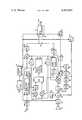
- An IR decode unit 11is shown for receiving transmitted IR command signals and effecting a desired function in a control unit 10.
- Control unit 10may include a number of functions as mentioned above as well as include appropriate tuning circuitry for television signals. It specifically includes three outputs, one marked V (volume), another marked P (privacy) and a third marked T (telephone). While the control unit will usually have additional outputs, only the three mentioned ones are of interest to this invention.
- the T output of control unit 10is connected to a switch 23 and to a telephone interface circuit 20 which includes a conventional telephone induction coil 21 and suitable means such as a hook switch relay (not shown), for disconnecting the telephone ring circuit and connecting the telephone talk circuit across the telephone lines.
- the ring circuit(not shown) supplies a ring detector 22, which is responsive to the 20 Hz ringing signal commonly used in telephone systems.
- the ring detectoris coupled to an analog to digital (A/D) detector 24 where the 20 Hz ring signal is "digitized" and supplied to a tone generator 25 and a holding circuit 26.
- A/Danalog to digital
- the output of the holding circuitis supplied to a digital to analog (D/A) converter 27 where the digitized signal is converted to an analog signal and supplied to an amplifier 28 and used to drive a visual indicator 29.
- the signal indicatormay be a LED (light-emitting diode), for example.
- the output of a D/A converter 27is also used to control switch 58 during an incoming ring signal.
- Switch 23is connected to another switch 58 in the listen channel.
- Switch 58has two signal inputs, one from the normal television audio circuit 61 and the other from the output of a D/A converter 56 of the listen channel.
- the output of tone generator 25, which is simply a sine wave oscillator,is approximately a 600 Hz signal. This signal is supplied during an incoming ring signal to the input of a D/A converter 56 and consequently operation of switch 58 disconnects the normal TV audio signal and connects the tone generator signal to a volume control 59 in an amplifier which drives a speaker 60.
- the television vieweris alerted to an incoming telephone call by an audible ring signal from the television speaker and by visual indicator 29.
- the viewer"answers" the telephone by sending the appropriate IR command signal for energizing the T output of control unit 10 to operate the mechanism in telephone interface circuit 20.
- the ringing circuitis switched out and the induction coil connected across the telephone lines and switch 23 operates, resulting in switch 58 operating to connect the listen channel to the audio output circuitry of the television receiver.
- the talk channelincludes a microphone 30 supplying an amplifier 31, the output of which is coupled to an A/D converter 32 where the amplified analog microphone signal is digitized, that is, has discrete numerical values assigned to various amplitude levels.
- the output of A/D converter 32is sent directly to a gain-controlled amplifier or multiplier 35 having its output supplied to a D/A converter 36, which reconverts the signal into analog form and supplies it to induction coil 21 in telephone interface 20.
- the output of A/D converter 32is also supplied to a signal level detector 33 which in turn has an output supplied to a background noise cancelling circuit 34.
- the output of background circuit 34is supplied to the input of a variable gain amplifier (multiplier) 40.
- variable gain amplifier 40is supplied from the listen channel.
- the output of variable gain amplifier 40is supplied to an inhibit circuit 41 which is coupled to the P output of control unit 10. The viewer may energize this ouptut by an appropriate IR command signal when it is desired to keep sounds in the room picked up by microphone 30 from being coupled to the telephone lines.
- the output of inhibit circuit 41is supplied as one input to a substraction circuit 43, the other input of which comes from the listen channel.
- Subtraction circuit 43develops an output based upon the larger of its two input signals and supplies an appropriate switching signal to a switch control generator 44 which has two outputs A and B.
- Outputs A and Bare selectively energized, with output A controlling the gain of gain-controlled amplifier 35 in the talk channel and output B controlling the gain of gain-controlled amplifier 55 in the listen channel.
- Output Ais also coupled to a scaling circuit 37 for controlling the gain of variable gain amplifier 42.
- output Bis coupled to a scaling circuit 57 for controlling the gain of variable gain amplifier 40.
- the scaling circuitsare designated 1-A and 1-B which means that the digital signals on outputs A and B are subtracted from 1.
- the digital signals at outputs A and Bvary from 0 to 1.
- the listen channelis connected to induction coil 21 in the telephone interface through a DC blocking capacitor 51 which supplies analog signals to an A/D converter 52 which digitizes them.
- the output of the A/D converteris directly supplied to gain-controlled amplifier 55 which, in turn, supplies D/A converter 56, as explained previously.
- the output of A/D converter 52is also supplied to a signal level detector 53 similar to signal level detector 33 in the talk channel.
- the output of detector 53is supplied to an amplifier 54 prior to being supplied to an input of variable gain amplifier 42.
- the output of amplifier 42is, as noted before, supplied to subtraction circuit 43.
- the additional amplifier 54 in the listen channelis included to increase the sensitivity of the listen channel since it is subject to many more variables such as signal level, noise, line losses, etc. and as mentioned previously is considered to be uncontrollable in comparison with the talk channel.
- switch control generator 44determines the gain of the respective gain-controlled amplifiers 35 and 55.
- Switch control generator 44selectively energizes outputs A and B which are normally at digital 0 indicating that the multipliers to which they are connected are substantially disabled.
- channel control meansare provided for switching the channels as a function of signals therein. These channel control means include scaling circuits 37 and 57, variable gain amplifiers 40 and 42, differential means, in the form of subtraction circuits 43, and switch control generator 44.
- the channel control means of the inventionsenses the signal level in a channel and increases the gain of that channel as a function of the sensed signal level and offsets cross coupled signals by desensitizing the other channel. Consequently, rather than trying to "null out” the inherent cross coupling in the telephone lines, the invention simply nullifies its effect by offsetting cross coupling signals. For example, a strong signal in the talk channel will result in high gain in that channel and a correspondingly large cross coupled signal in the listen channel.
- the gain control factor (A) applied to the gain-controlled amplifier in the talk channelis scaled and the resultant (1-A) gain factor "multiplied" with the signal level in the listen channel and applied to the subtraction circuit.
- the signal level in the talk channelis multiplied by the scaled gain control factor of the listen channel (1-B) which is very close to 1 and applied to the subtraction circuit.
- the output of the subtraction circuitdetermines which channel is on and at what gain factor.
- the threshold of prior art circuitsis eliminated and cross coupled signals are offset. Weak signals are offset slightly and strong signals are offset strongly. Digitizing the signals yields extremely accurate amplitude levels and predictable results.
- the very high speed gain control and switchingyields a television receiver two-way communication channel that approaches the performance of a conventional telephone system.
- the systemis capable of switching the channels in mid-syllable.
- signal level detectors 33 and 53may each comprise an absolute value detector circuit in series with a peak detector circuit which, in turn, supplies a decay circuit of approximately 100 milliseconds.
- Background noise cancelling circuit 34may be incorporated for those situations where relatively constant noise signals are present such as when an air conditioner is running.
- This circuitmay comprise a very long time constant filter, on the order of 0.1 Hz, and an override arrangement to enable quick response in the event that the constant background noise source is suddenly turned off.
- One approachwould include a substraction circuit that is supplied with the long time constant output from the filter and with the output of the 100 millisecond decay circuit in the signal level detector.
- the output of the subtraction circuitwould be supplied to a comparator along with the direct output of the 100 millisecond decay circuit with the comparator output constituting the output of the background noise cancellation circuit.
- Such an arrangementprecludes background noise from desensitizing the other channel and avoids the difficulty inherent in using long time constant filters which are incapable of responding to changes in background noise.
- Switch control generator 44may comprise a parallel arrangement of a positive peak detector, a negative peak detector and a zero crossing detector.
- the peak detectorssupply the input of a pair of "decay to zero" circuits of approximately 100 millisecond duration and the zero crossing detector supplies a reset for the decay circuits.
- a computer programis attached as an appendix.
Landscapes
- Engineering & Computer Science (AREA)
- Signal Processing (AREA)
- Interconnected Communication Systems, Intercoms, And Interphones (AREA)
Abstract
Description
Claims (10)
Priority Applications (2)
| Application Number | Priority Date | Filing Date | Title |
|---|---|---|---|
| US06/433,344US4465902A (en) | 1982-10-08 | 1982-10-08 | Digital space phone system |
| CA000427002ACA1192992A (en) | 1982-10-08 | 1983-04-29 | Digital space phone system |
Applications Claiming Priority (1)
| Application Number | Priority Date | Filing Date | Title |
|---|---|---|---|
| US06/433,344US4465902A (en) | 1982-10-08 | 1982-10-08 | Digital space phone system |
Publications (1)
| Publication Number | Publication Date |
|---|---|
| US4465902Atrue US4465902A (en) | 1984-08-14 |
Family
ID=23719829
Family Applications (1)
| Application Number | Title | Priority Date | Filing Date |
|---|---|---|---|
| US06/433,344Expired - LifetimeUS4465902A (en) | 1982-10-08 | 1982-10-08 | Digital space phone system |
Country Status (2)
| Country | Link |
|---|---|
| US (1) | US4465902A (en) |
| CA (1) | CA1192992A (en) |
Cited By (18)
| Publication number | Priority date | Publication date | Assignee | Title |
|---|---|---|---|---|
| US4513177A (en)* | 1980-12-09 | 1985-04-23 | Nippon Telegraph & Telephone Public Corporation | Loudspeaking telephone system |
| US4560840A (en)* | 1983-03-01 | 1985-12-24 | International Standard Electric Corporation | Digital handsfree telephone |
| US4571461A (en)* | 1983-04-18 | 1986-02-18 | Nec Corporation | Conference telephone apparatus |
| US4677661A (en)* | 1983-10-07 | 1987-06-30 | Baccaret Teledex, Inc. | Microprocessor controlled telephone unit |
| US4775996A (en)* | 1987-09-30 | 1988-10-04 | Northern Telecom Limited | Hybrid telephony communication system |
| US4796287A (en)* | 1985-05-10 | 1989-01-03 | Mitel Corp. | Digital loudspeaking telephone |
| US4805206A (en)* | 1985-08-24 | 1989-02-14 | Sam Sung Electronics Co. Ltd. | Function controller serving as an automatic telephone answering machine in an audio/video component system |
| US5138649A (en)* | 1990-11-16 | 1992-08-11 | General Instrument Corporation | Portable telephone handset with remote control |
| US5570415A (en)* | 1991-08-29 | 1996-10-29 | Sasktel | Video programming and storage control using the telephone network |
| US5802467A (en)* | 1995-09-28 | 1998-09-01 | Innovative Intelcom Industries | Wireless and wired communications, command, control and sensing system for sound and/or data transmission and reception |
| US5867540A (en)* | 1995-12-19 | 1999-02-02 | Hyundai Electronics Industries Co., Ltd. | Echo removing system between a mobile communication subscriber and a fixed communication subscriber |
| US6031825A (en)* | 1992-08-18 | 2000-02-29 | Nokia Mobile Phones Limited | Infrared audio link in mobile phone |
| US20020194587A1 (en)* | 2001-03-13 | 2002-12-19 | Lampton David P. | Enhanced communication, monitoring and control system |
| US8364136B2 (en) | 1999-02-01 | 2013-01-29 | Steven M Hoffberg | Mobile system, a method of operating mobile system and a non-transitory computer readable medium for a programmable control of a mobile system |
| US8369967B2 (en) | 1999-02-01 | 2013-02-05 | Hoffberg Steven M | Alarm system controller and a method for controlling an alarm system |
| US8892495B2 (en) | 1991-12-23 | 2014-11-18 | Blanding Hovenweep, Llc | Adaptive pattern recognition based controller apparatus and method and human-interface therefore |
| US9137354B2 (en) | 1998-12-19 | 2015-09-15 | Samsung Electronics Co., Ltd | Portable television (TV) phone and method for controlling operation thereof |
| US10361802B1 (en) | 1999-02-01 | 2019-07-23 | Blanding Hovenweep, Llc | Adaptive pattern recognition based control system and method |
Citations (6)
| Publication number | Priority date | Publication date | Assignee | Title |
|---|---|---|---|---|
| US3660603A (en)* | 1968-08-29 | 1972-05-02 | Philips Corp | Speech-controlled bilateral amplifier |
| US3925618A (en)* | 1974-05-02 | 1975-12-09 | Nippon Telegraph & Telephone | Voice switch circuits for use in loudspeaking telephone circuits |
| US3953676A (en)* | 1974-12-12 | 1976-04-27 | Northern Electric Company, Limited | Digital control of a loudspeaking telephone system |
| JPS5797262A (en)* | 1980-12-09 | 1982-06-16 | Nippon Telegr & Teleph Corp <Ntt> | Loud speaker telephone set system |
| US4338492A (en)* | 1980-01-02 | 1982-07-06 | Zenith Radio Corporation | Television receiver with two-way telephone conversation capability |
| US4414432A (en)* | 1981-09-21 | 1983-11-08 | Zenith Radio Corporation | Pseudo-full duplex television/telephone loudspeaker system |
- 1982
- 1982-10-08USUS06/433,344patent/US4465902A/ennot_activeExpired - Lifetime
- 1983
- 1983-04-29CACA000427002Apatent/CA1192992A/ennot_activeExpired
Patent Citations (6)
| Publication number | Priority date | Publication date | Assignee | Title |
|---|---|---|---|---|
| US3660603A (en)* | 1968-08-29 | 1972-05-02 | Philips Corp | Speech-controlled bilateral amplifier |
| US3925618A (en)* | 1974-05-02 | 1975-12-09 | Nippon Telegraph & Telephone | Voice switch circuits for use in loudspeaking telephone circuits |
| US3953676A (en)* | 1974-12-12 | 1976-04-27 | Northern Electric Company, Limited | Digital control of a loudspeaking telephone system |
| US4338492A (en)* | 1980-01-02 | 1982-07-06 | Zenith Radio Corporation | Television receiver with two-way telephone conversation capability |
| JPS5797262A (en)* | 1980-12-09 | 1982-06-16 | Nippon Telegr & Teleph Corp <Ntt> | Loud speaker telephone set system |
| US4414432A (en)* | 1981-09-21 | 1983-11-08 | Zenith Radio Corporation | Pseudo-full duplex television/telephone loudspeaker system |
Cited By (21)
| Publication number | Priority date | Publication date | Assignee | Title |
|---|---|---|---|---|
| US4513177A (en)* | 1980-12-09 | 1985-04-23 | Nippon Telegraph & Telephone Public Corporation | Loudspeaking telephone system |
| US4560840A (en)* | 1983-03-01 | 1985-12-24 | International Standard Electric Corporation | Digital handsfree telephone |
| US4571461A (en)* | 1983-04-18 | 1986-02-18 | Nec Corporation | Conference telephone apparatus |
| US4677661A (en)* | 1983-10-07 | 1987-06-30 | Baccaret Teledex, Inc. | Microprocessor controlled telephone unit |
| US4796287A (en)* | 1985-05-10 | 1989-01-03 | Mitel Corp. | Digital loudspeaking telephone |
| US4805206A (en)* | 1985-08-24 | 1989-02-14 | Sam Sung Electronics Co. Ltd. | Function controller serving as an automatic telephone answering machine in an audio/video component system |
| US4775996A (en)* | 1987-09-30 | 1988-10-04 | Northern Telecom Limited | Hybrid telephony communication system |
| US5138649A (en)* | 1990-11-16 | 1992-08-11 | General Instrument Corporation | Portable telephone handset with remote control |
| US5570415A (en)* | 1991-08-29 | 1996-10-29 | Sasktel | Video programming and storage control using the telephone network |
| US8892495B2 (en) | 1991-12-23 | 2014-11-18 | Blanding Hovenweep, Llc | Adaptive pattern recognition based controller apparatus and method and human-interface therefore |
| US6031825A (en)* | 1992-08-18 | 2000-02-29 | Nokia Mobile Phones Limited | Infrared audio link in mobile phone |
| US5802467A (en)* | 1995-09-28 | 1998-09-01 | Innovative Intelcom Industries | Wireless and wired communications, command, control and sensing system for sound and/or data transmission and reception |
| US5867540A (en)* | 1995-12-19 | 1999-02-02 | Hyundai Electronics Industries Co., Ltd. | Echo removing system between a mobile communication subscriber and a fixed communication subscriber |
| US9137354B2 (en) | 1998-12-19 | 2015-09-15 | Samsung Electronics Co., Ltd | Portable television (TV) phone and method for controlling operation thereof |
| US9628862B2 (en) | 1998-12-19 | 2017-04-18 | Samsung Electronics Co., Ltd | Portable phone and method for providing incoming message notifications during video operations thereof |
| US8364136B2 (en) | 1999-02-01 | 2013-01-29 | Steven M Hoffberg | Mobile system, a method of operating mobile system and a non-transitory computer readable medium for a programmable control of a mobile system |
| US8369967B2 (en) | 1999-02-01 | 2013-02-05 | Hoffberg Steven M | Alarm system controller and a method for controlling an alarm system |
| US8583263B2 (en) | 1999-02-01 | 2013-11-12 | Steven M. Hoffberg | Internet appliance system and method |
| US9535563B2 (en) | 1999-02-01 | 2017-01-03 | Blanding Hovenweep, Llc | Internet appliance system and method |
| US10361802B1 (en) | 1999-02-01 | 2019-07-23 | Blanding Hovenweep, Llc | Adaptive pattern recognition based control system and method |
| US20020194587A1 (en)* | 2001-03-13 | 2002-12-19 | Lampton David P. | Enhanced communication, monitoring and control system |
Also Published As
| Publication number | Publication date |
|---|---|
| CA1192992A (en) | 1985-09-03 |
Similar Documents
| Publication | Publication Date | Title |
|---|---|---|
| US4465902A (en) | Digital space phone system | |
| US5384843A (en) | Hands-free telephone set | |
| US4414432A (en) | Pseudo-full duplex television/telephone loudspeaker system | |
| US4712231A (en) | Teleconference system | |
| US4433435A (en) | Arrangement for reducing the noise in a speech signal mixed with noise | |
| US5835610A (en) | Hearing air system | |
| JP2606171B2 (en) | Receiving volume automatic variable circuit | |
| US5857019A (en) | Apparatus and method for providing a telephone user with control of the threshold volume at which the user's voice will take control of a half-duplex speakerphone conversation | |
| US5870453A (en) | Automatic control system for a remotely controllable sound producing device | |
| JPS61270961A (en) | Method and apparatus for controlling gain of speaker phone | |
| CA2025002C (en) | Automatic mixer apparatus | |
| US7130413B2 (en) | Microprocessor-controlled full-duplex speakerphone using automatic gain control | |
| EP0187696A2 (en) | Full duplex conferencing system | |
| US2258807A (en) | Communication system | |
| JPH05175769A (en) | Electronic device | |
| JPH0435144A (en) | Telephone system | |
| JPH0383491A (en) | Acoustic echo canceler device | |
| GB2209906A (en) | Telephone instrument | |
| KR910001082Y1 (en) | Circuit to suppress noise in the handset | |
| JPH0522382A (en) | Telephone | |
| JPS59111425A (en) | Conference telephone set | |
| JPS63280551A (en) | Phone call volume adjustment method | |
| JPS6130161A (en) | Audio conference device | |
| CA1110704A (en) | Level control circuitry for two way communication system | |
| JPH0739114U (en) | Automatic volume control |
Legal Events
| Date | Code | Title | Description |
|---|---|---|---|
| AS | Assignment | Owner name:ZENITH ELECTRONICS CORPORATION, 1000 MILWAUKEE AVE Free format text:ASSIGNMENT OF ASSIGNORS INTEREST.;ASSIGNOR:ZATO, THOMAS J.;REEL/FRAME:004263/0107 Effective date:19840531 Owner name:ZENITH ELECTRONICS CORPORATION,ILLINOIS Free format text:ASSIGNMENT OF ASSIGNORS INTEREST;ASSIGNOR:ZATO, THOMAS J.;REEL/FRAME:004263/0107 Effective date:19840531 | |
| STCF | Information on status: patent grant | Free format text:PATENTED CASE | |
| FEPP | Fee payment procedure | Free format text:PAYOR NUMBER ASSIGNED (ORIGINAL EVENT CODE: ASPN); ENTITY STATUS OF PATENT OWNER: LARGE ENTITY | |
| FPAY | Fee payment | Year of fee payment:4 | |
| FPAY | Fee payment | Year of fee payment:8 | |
| AS | Assignment | Owner name:FIRST NATIONAL BANK OF CHICAGO, THE Free format text:SECURITY INTEREST;ASSIGNOR:ZENITH ELECTRONICS CORPORATION A CORP. OF DELAWARE;REEL/FRAME:006187/0650 Effective date:19920619 | |
| AS | Assignment | Owner name:ZENITH ELECTRONICS CORPORATION Free format text:RELEASED BY SECURED PARTY;ASSIGNOR:FIRST NATIONAL BANK OF CHICAGO, THE (AS COLLATERAL AGENT).;REEL/FRAME:006243/0013 Effective date:19920827 | |
| FPAY | Fee payment | Year of fee payment:12 |