US4465481A - Single piece wound drain catheter - Google Patents
Single piece wound drain catheterDownload PDFInfo
- Publication number
- US4465481A US4465481AUS06/371,941US37194182AUS4465481AUS 4465481 AUS4465481 AUS 4465481AUS 37194182 AUS37194182 AUS 37194182AUS 4465481 AUS4465481 AUS 4465481A
- Authority
- US
- United States
- Prior art keywords
- segment
- die
- drain
- catheter
- tube segment
- Prior art date
- Legal status (The legal status is an assumption and is not a legal conclusion. Google has not performed a legal analysis and makes no representation as to the accuracy of the status listed.)
- Expired - Lifetime
Links
- 239000000463materialSubstances0.000claimsabstractdescription86
- 230000007704transitionEffects0.000claimsabstractdescription71
- 239000012530fluidSubstances0.000claimsabstractdescription31
- 238000000034methodMethods0.000claimsabstractdescription29
- 229920001296polysiloxanePolymers0.000claimsdescription6
- 229940079593drugDrugs0.000claimsdescription2
- 239000003814drugSubstances0.000claimsdescription2
- 238000010276constructionMethods0.000claims1
- 206010052428WoundDiseases0.000abstractdescription40
- 208000027418Wounds and injuryDiseases0.000abstractdescription40
- 238000001125extrusionMethods0.000abstractdescription36
- 230000008569processEffects0.000abstractdescription25
- 229920002379silicone rubberPolymers0.000abstractdescription4
- 230000008859changeEffects0.000abstractdescription3
- 208000015943Coeliac diseaseDiseases0.000description32
- 238000004519manufacturing processMethods0.000description5
- 230000009467reductionEffects0.000description4
- 230000015572biosynthetic processEffects0.000description3
- 230000008030eliminationEffects0.000description2
- 238000003379elimination reactionMethods0.000description2
- XBWAZCLHZCFCGK-UHFFFAOYSA-N7-chloro-1-methyl-5-phenyl-3,4-dihydro-2h-1,4-benzodiazepin-1-ium;chlorideChemical compound[Cl-].C12=CC(Cl)=CC=C2[NH+](C)CCN=C1C1=CC=CC=C1XBWAZCLHZCFCGK-UHFFFAOYSA-N0.000description1
- 230000009471actionEffects0.000description1
- 230000009286beneficial effectEffects0.000description1
- 235000012438extruded productNutrition0.000description1
- 230000035876healingEffects0.000description1
- 230000006872improvementEffects0.000description1
- 210000001503jointAnatomy0.000description1
- 230000007246mechanismEffects0.000description1
- 239000012768molten materialSubstances0.000description1
- 230000004044responseEffects0.000description1
- 238000000926separation methodMethods0.000description1
- 230000008467tissue growthEffects0.000description1
Images


Classifications
- A—HUMAN NECESSITIES
- A61—MEDICAL OR VETERINARY SCIENCE; HYGIENE
- A61M—DEVICES FOR INTRODUCING MEDIA INTO, OR ONTO, THE BODY; DEVICES FOR TRANSDUCING BODY MEDIA OR FOR TAKING MEDIA FROM THE BODY; DEVICES FOR PRODUCING OR ENDING SLEEP OR STUPOR
- A61M25/00—Catheters; Hollow probes
- A61M25/0021—Catheters; Hollow probes characterised by the form of the tubing
- A61M25/0023—Catheters; Hollow probes characterised by the form of the tubing by the form of the lumen, e.g. cross-section, variable diameter
- A61M25/0026—Multi-lumen catheters with stationary elements
- A61M25/0029—Multi-lumen catheters with stationary elements characterized by features relating to least one lumen located at the middle part of the catheter, e.g. slots, flaps, valves, cuffs, apertures, notches, grooves or rapid exchange ports
- A—HUMAN NECESSITIES
- A61—MEDICAL OR VETERINARY SCIENCE; HYGIENE
- A61M—DEVICES FOR INTRODUCING MEDIA INTO, OR ONTO, THE BODY; DEVICES FOR TRANSDUCING BODY MEDIA OR FOR TAKING MEDIA FROM THE BODY; DEVICES FOR PRODUCING OR ENDING SLEEP OR STUPOR
- A61M27/00—Drainage appliance for wounds or the like, i.e. wound drains, implanted drains
- A—HUMAN NECESSITIES
- A61—MEDICAL OR VETERINARY SCIENCE; HYGIENE
- A61M—DEVICES FOR INTRODUCING MEDIA INTO, OR ONTO, THE BODY; DEVICES FOR TRANSDUCING BODY MEDIA OR FOR TAKING MEDIA FROM THE BODY; DEVICES FOR PRODUCING OR ENDING SLEEP OR STUPOR
- A61M25/00—Catheters; Hollow probes
- A61M25/0021—Catheters; Hollow probes characterised by the form of the tubing
- A61M25/0023—Catheters; Hollow probes characterised by the form of the tubing by the form of the lumen, e.g. cross-section, variable diameter
- A61M25/0026—Multi-lumen catheters with stationary elements
- A61M2025/0034—Multi-lumen catheters with stationary elements characterized by elements which are assembled, connected or fused, e.g. splittable tubes, outer sheaths creating lumina or separate cores
- A—HUMAN NECESSITIES
- A61—MEDICAL OR VETERINARY SCIENCE; HYGIENE
- A61M—DEVICES FOR INTRODUCING MEDIA INTO, OR ONTO, THE BODY; DEVICES FOR TRANSDUCING BODY MEDIA OR FOR TAKING MEDIA FROM THE BODY; DEVICES FOR PRODUCING OR ENDING SLEEP OR STUPOR
- A61M25/00—Catheters; Hollow probes
- A61M25/0021—Catheters; Hollow probes characterised by the form of the tubing
- A61M25/0023—Catheters; Hollow probes characterised by the form of the tubing by the form of the lumen, e.g. cross-section, variable diameter
- A61M25/0026—Multi-lumen catheters with stationary elements
- A61M2025/004—Multi-lumen catheters with stationary elements characterized by lumina being arranged circumferentially
- A—HUMAN NECESSITIES
- A61—MEDICAL OR VETERINARY SCIENCE; HYGIENE
- A61M—DEVICES FOR INTRODUCING MEDIA INTO, OR ONTO, THE BODY; DEVICES FOR TRANSDUCING BODY MEDIA OR FOR TAKING MEDIA FROM THE BODY; DEVICES FOR PRODUCING OR ENDING SLEEP OR STUPOR
- A61M25/00—Catheters; Hollow probes
- A61M25/0021—Catheters; Hollow probes characterised by the form of the tubing
- A61M25/0023—Catheters; Hollow probes characterised by the form of the tubing by the form of the lumen, e.g. cross-section, variable diameter
- A61M25/0026—Multi-lumen catheters with stationary elements
- A61M25/003—Multi-lumen catheters with stationary elements characterized by features relating to least one lumen located at the distal part of the catheter, e.g. filters, plugs or valves
- A—HUMAN NECESSITIES
- A61—MEDICAL OR VETERINARY SCIENCE; HYGIENE
- A61M—DEVICES FOR INTRODUCING MEDIA INTO, OR ONTO, THE BODY; DEVICES FOR TRANSDUCING BODY MEDIA OR FOR TAKING MEDIA FROM THE BODY; DEVICES FOR PRODUCING OR ENDING SLEEP OR STUPOR
- A61M25/00—Catheters; Hollow probes
- A61M25/0067—Catheters; Hollow probes characterised by the distal end, e.g. tips
- A61M25/0068—Static characteristics of the catheter tip, e.g. shape, atraumatic tip, curved tip or tip structure
- A61M25/0071—Multiple separate lumens
Definitions
- the present inventionrelates to wound drain catheters for draining fluid from, or supplying medication to, a wound.
- Virtually all wound drain catheters presently used in closed woundscomprise a drain section for fluid communication with the wound and a separate outflow or extension tube section for carrying the fluid between the drain section and a reservoir.
- the drain section of a wound drain cathetercomprises a length of tubing that is perforated by forming small apertures through the tubing wall.
- the advantages of a drain of this design over the drains of the prior artinclude an increased lumenal flow drainage area, elimination of stress points in the drain section that may lead to breakage of the drain as it is removed from the patient's body, and reduction of the risk that tissue growth will inhibit removal of drain.
- the drain portion there disclosedmust be attached to a separate outflow tube.
- a butt jointis formed between the ends of the drain and the tube, with the two portions connected by an exterior collar.
- the end of the drain portionis undercut to provide a semi-spherical recess for fluid communication between the lumens and the outflow tube.
- the collarwhich necessarily has an outer diameter larger than the diameter of the drain portion and the extension tube portion, may provide added resistance to removal of the catheter. Although the possibility of this collar binding on material as it is pulled through the body is remote, the segment of increased diameter may give rise to added friction between the drain and the flesh surrounding it as the drain is pulled out of the body. In addition, forming the semi-spherical recess in the drain portion and attaching the drain portion to the outflow tube require additional steps during the manufacture of the catheter, making manufacture more time-consuming and expensive than the manufacture of a single piece catheter in a single process. Thus, while the drain catheter disclosed in patent application Ser. No. 238,640 substantially improved upon the prior art, room for further improvement remained.
- the dies presently used in the extrusion of silicone or plastic materialscomprise a die nozzle having a die cavity from which a parison is extruded.
- the die cavityhas fixed within it die forms and/or die mandrels, around which the material flows as it is extruded from the die cavity to form a parison of the desired shape.
- Most of the die forms and die mandrels of the dies presently in useare fixed in place within the die cavity during the extrusion process.
- a few deviceshave a central die mandrel that has limited linear movement to vary the wall thickness of a tubular parison. But, to change the shape of the parison, the extrusion process must be halted, the dies moved or changed, and the extrusion process begun again.
- the present inventioncomprises a wound drain catheter formed of a single continuous elongate member of silicone material and the die for making such a catheter.
- the wound drain catheter of the present inventionincorporates into a single member a drain segment, a transition tube segment, and an extension tube segment.
- the drain segment of the present inventioncomprises a fluted body with one or more longitudinal lumens, each open to the wound surrounding the drain segment.
- the transition tube segmentallows fluid to flow from the lumens of the drain segment to the tubular extension tube segment.
- the end of the extension tube segmentis connected to a reservoir for collecting or supplying fluid.
- the drain segment of the preferred embodiment of the catheter of the present inventionincorporates the design of the drain section of the wound drain catheter of applicant's co-pending application Ser. No. 238,640, filed Feb. 26, 1981.
- the drain section therein disclosedcomprises a central core with strut portions projecting radially therefrom.
- An overhang portionis provided at the end of each of the strut portions, thereby forming "T"-shaped members.
- the overhang portions and strut portionscooperate to form channels or lumens extending throughout the length of the drain portion, each of which is open to the wound.
- the drain segmentis formed as part of a single unit with a transition tube segment comprising a central core with strut portions projecting radially therefrom and a tubular portion connected on its inner surface with the outer ends of the strut portions, so the tubular portion and the strut portions cooperate to define enclosed longitudinal channels in the transition tube segment.
- the strut portions of the transition tube segmentare colinear with the strut portions of the drain segment so fluid flowing through each of the lumens of the drain segment flows into one of the channels of the transition tube segment.
- the single unit drain catheter of the present inventionalso includes an extension tube segment comprising a tubular portion defining a central longitudinal cavity. One end of this segment is in fluid communication with all of the channels of the transition tube segment. The other end of the extension tube segment is connected to the reservoir.
- the elongate memberis preferably formed of two materials extruded as a single unit.
- a first materialwhich is translucent, forms the tubular portion of the extension tube segment and the tubular portion of the transition tube segment.
- a second materialwhich is radiopaque, forms the core portion of the drain segment and the core portion of the transition tube segment.
- catheter of the present inventionhaving smaller diameters than the diameter of the drain of the first embodiment. These smaller drains are suitable for smaller wounds requiring less fluid drainage.
- the drain segmentcomprises a core portion with two curved outer portions formed on opposite sides of the core portion. Each of these outer portions encircles less than one-half the circumference of the core portion, defining two longitudinal lumens between them.
- the transition tube segment of this embodimentcomprises two separate outer curved portions that are extensions of the outer curved portions of the drain segment, defining diametrically between them a central longitudinal cavity that is continuous with the cavity of the extension tube segment and defining circumferentially between them two channels that are continuous with the lumens of the drain segment, the channels communicating along their lengths with the central opening.
- the tubular extension tube segment of this embodimentis formed as a single unit with the transition tube segment and the drain segment.
- a single longitudinal lumenis provided in the drain segment.
- the drain segmentcomprises a substantially cylindrical body with a groove formed in the outer surface.
- the transition tube segment of this embodimentis also formed as a single unit with the drain segment and comprises an enclosed channel in fluid communication at one end with the single longitudinal lumen of the drain segment and at the other end with the longitudinal cavity of the extension tube segment.
- the drain segment of the catheter of any of the above-described embodimentsis preferrably formed at least partially of radiopaque material, while the extension segment is formed of translucent material.
- the drain of the inventionis formed of a silicone elastomer having substantial tensile strength and elasticity.
- forming the entire wound drain catheter as a single uniteliminates the joint previously necessary between the drain section and the extension tube section, thus eliminating the collar holding the two sections together.
- the external diameter of the catheterremains virtually constant throughout its length, with no collar of diameter greater than the diameter of the catheter present to provide resistance to removal of the drain from the patient's body. Also eliminated is the possibility of separation of the drain section from the extension tube section at the joint.
- forming the entire drain catheter unit from a silicone elastomerprovides the transition tube segment and the extension tube segment with the reduction in cross sectional area capability previously found to be advantageous for the drain segment.
- transition tube segmentand possibly a portion of the extension tube segment, is within the patient's body when the drain segment is positioned in the closed, deep wound.
- providing a transition tube segment and extension tube segment that reduce in cross sectional area in response to a tensile forceallows the drain of the present invention to be removed from the patient's body with a minimum of effort by the surgeon and a minimum of pain to the patient.
- the present inventionadditionally comprises a die for making a single piece wound drain catheter, such as those just described.
- the die of the present inventionincludes die forms and die mandrels within the die cavity that can be moved between positions while the parison is being extruded to change the shape of the parison during a single extrusion process, permitting the formation of a single, continuous parison that has a cross section that is not uniform throughout its length. This permits the formation of the wound drain catheter of the present invention that comprises a single continuous elongate member incorporating a drain segment, a transition tube segment, and an extension tube segment.
- the wound drain catheter of the first embodiment of the present inventionmay be formed by placing in the die cavity a first die form consisting of four prongs adjacent to the outer edge of the die cavity, a first die mandrel having a second die form on its end for forming the core portion and the projecting strut portions of the drain segment and the transition tube segment, and a second die mandrel that fills the second die form to form with the first die mandrel a cylindrical structure.
- the drain segmentis formed by placing in the die cavity the first die form and the first die mandrel.
- the first die mandrel with the second die form on its endshapes the parison into the main body of the drain segment, while the prongs of the first die form create in the parison the longitudinal grooves that allow the lumens of the drain segment to communicate with the surrounding wound.
- the first die formis removed from the die cavity while the extrusion process continues, which eliminates the grooves and provides the closed exterior surface defining the internal closed channels of the transition tube segment.
- the extension tube segmentis then formed by sliding the inner die mandrel into the die form on the end of the first die mandrel to form a cylindrical die mandrel around which the tubular portion of the extension tube segment is formed.
- Different embodiments of the die of the present inventionare used to extrude the smaller drains of the present invention.
- the drain having two lumenscan be formed with a die having a linearly movable first die form consisting of two prongs adjacent the outer edge of the die cavity, forming in the parison the two lumens of the drain segment.
- a cylindrical die mandrel for forming in the parison the central cavity of the extension tube segmentis brought into the die cavity.
- the very short transition tube segmentis formed when both the first die form and the cylindrical die mandrel are simultaneously positioned in the die cavity for a brief time during the extrusion process.
- a single die pinis provided in the die cavity.
- this pinis positioned adjacent the edge of the die cavity, where the pin forms in the parison the single longitudinal lumen.
- the pinis moved toward the center of the die cavity, forming the transition tube segment.
- the pinis a die mandrel around which the extension tube is formed.
- Applicanthas invented a new wound drain catheter comprising, in a single unit, a drain segment, a transition tube segment, and an extension tube segment.
- This wound drain catheterprovides substantial advantages over those of the prior art, including increased lumenal flow drainage area, increased drain body cross sectional area, reduction of the possibility of breakage of the drain segment during removal, elimination of the possibility of rupture of the joint between the drain segment and the outflow tube segment, increased ease of removal of the drain from the patient's body, and reduced pain to the patient associated with removal of the drain.
- Applicant's inventionalso comprises a new die useful for extruding the drain of the present invention and other products that are not uniform in cross section throughout their lengths.
- This dieincludes die forms and die mandrels in the die cavity that are movable during the extrusion process to alter the shape of the parison being extruded from the die.
- the die of the present inventionis useful for the extrusion of a variety of products, including, but not limited to, the drain of the present invention.
- FIG. 1is a perspective view of the die of the present invention.
- FIG. 2is an exploded perspective view of the die of the present invention.
- FIG. 3is a side cross sectional view of the assembled die of the present invention.
- FIG. 4is an exploded perspective view of the die form and die mandrels that fit in the die opening.
- FIG. 5is a perspective view of the die form and die mandrels assembled to fit in the die opening.
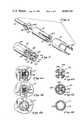
- FIG. 6ais an end view of the die nozzle with the die mandrels and die form positioned to extrude the drain segment of the catheter.
- FIG. 6bis a cross sectional view of the drain segment of the catheter, taken along line 6b--6b of FIG. 10.
- FIG. 7ais an end view of the die nozzle with the die form and die mandrel positioned to extrude the transition tube segment of the catheter.
- FIG. 7bis a cross sectional view of the transition tube segment of the catheter, taken along line 7b--7b of FIG. 10.
- FIG. 8ais an end view of the die nozzle with the die form and die mandrels positioned to extrude the extension tube segment of the catheter.
- FIG. 8bis a cross sectional view of the extension tube segment of the catheter, taken along line 8a--8b of FIG. 10.
- FIG. 9is a perspective view of the catheter of the present invention.
- FIG. 10is an enlarged perspective view of a portion of the catheter of FIG. 9.
- FIG. 11is a side cross sectional view of the catheter, taken along line 11--11 of FIG. 10.
- FIG. 11ais a perspective view of the breaker plate of the die showing the flow of material being extruded.
- FIG. 12is an exploded perspective view of a first alternate embodiment of the die of the present invention.
- FIG. 13is a perspective view of the die form and die mandrel of a second alternate embodiment of the die.
- FIG. 14ais an end view of the die nozzle of the second alternate embodiment of the die with the die form and die mandrel positioned to extrude the drain segment of a second alternate embodiment of the catheter.
- FIG. 14bis a cross sectional view of the drain segment of the second alternate embodiment of the catheter.
- FIG. 15ais an end view of the die nozzle of the second alternate embodiment of the die with the die form and die mandrel positioned to extrude the extension tube segment of the second alternate embodiment of the catheter.
- FIG. 15bis a cross sectional view of the extension tube segment of the second alternate embodiment of the catheter.
- FIG. 16is a perspective view of the second alternate embodiment of the catheter.
- FIG. 17ais a perspective view of the die mandrel of a third alternate embodiment of the die.
- FIG. 17bis an end view of the die nozzle of the third alternate embodiment of the die with the die mandrel positioned to extrude the drain segment of a third alternate embodiment of the catheter.
- FIG. 17cis an end view of the die nozzle of the third alternative embodiment of the die with the die mandrel positioned to extrude the extension tube segment of the third alternate embodiment of the catheter.
- FIG. 18ais an end view of the die nozzle of the third alternate embodiment of the die with the die mandrel positioned to extrude the drain segment of the third alternate embodiment of the catheter.
- FIG. 18bis a cross sectional view of the drain segment of the third alternate embodiment of the catheter.
- FIG. 19ais an end view of the die nozzle of the third alternate embodiment of the die with the die mandrel positioned to extrude the extension tube segment of the third alternate embodiment of the catheter.
- FIG. 19bis a cross sectional view of the extension tube segment of the third alternate embodiment of the catheter.
- FIG. 20is a perspective view of the third alternate embodiment of the catheter.
- FIG. 21is a side cross sectional view of the joint between the drain segment and the extension tube segment of a first alternate embodiment of the catheter.
- the catheter 111comprises a single continuous elongate member 115 comprising a drain segment 131, a second segment 151, called the transition tube segment, and a third segment 171, called the extension tube segment.
- the cross section of drain segment 131 shown in FIG. 6bshows the central core portion 133 with T-shaped members 137 projecting therefrom. T-shaped members 137 cooperate to form longitudinal flutes or lumens, comprising channels 136 communicating with the environment surrounding the drain through grooves 135.
- the drain segment 131 of the preferred embodimentis the same as the drain disclosed in applicant's U.S. patent application Ser. No. 238,640, filed Feb. 26, 1981.
- the core portion 133is best formed of a radiopaque material. This permits the location of the drain segment 131 to appear in X-rays taken of the wound area. To present a large image in X-rays portions of the strut portions 137 are also formed of radiopaque material.
- FIG. 7bshows the cross section of transition tube segment 151.
- Core portion 153is colinear with the core portion 133 of the drain segment 131.
- Each of the strut portions 155 projecting from core portion 153is colinear with one of the T-shaped portions 137 of the drain segment 131.
- the inner surface of tubular portion 159is connected to the ends of the strut portions 155 so the tubular portion 159 and the strut portions 155 cooperate to form enclosed longitudinal channels 156.
- Each of the channels 156communicates with one of the lumens 136 of the drain segment 131.
- the core portion 153 of the transition tube segment 151is advantageously formed of the radiopaque material of which the core portion 133 of the drain segment 131 is formed so it also will appear in X-rays of the patient.
- the tubular portion 159is best formed of a translucent material so the doctor or nurse can view the flow of fluid through the channels 156.
- the point of transition between the drain segment 131 and the transition tube segment 151is shown in longitudinal cross section in FIG. 11.
- the central core portion 133 of the drain segment 131continues into the central core portion 153 of the transition tube segment 151.
- the strut portions 155 and the tubular portion 159 of the transition tube segment 152are continuations of T-shaped members 137 of the drain segment 131, with grooves 135 of the drain segment filled in.
- Extension tube segment 171is shown in cross section in FIG. 8b.
- Extension tube segment 171comprises tubular portion 177 defining internal longitudinal cavity 175.
- Tubular portion 177is a continuation of tubular portion 159 so that cavity 175 communicates with all of the channels 156 of the transition tube segment 151.
- extension tube segment 171is formed of translucent material so the doctor or nurse can view the flow of fluid through cavity 175. Since, when the catheter is in use, the extension tube segment 171 is not within the patient's body, it need not be constructed of a radiopaque material that will show up on X-rays.
- each of the drain segment 131, the transition tube segment 151, and the extension tube segment 171are advantageously equal to one another, so the diameter of the elongate member 115 is constant throughout its length.
- FIG. 1the die is shown as assembled for extruding a parison, with breaker plate 31 and die nozzle 21 attached to main body 12 by screws 25. Die cavity 23 is centrally located in nozzle 21.
- first plenum 13Formed within the main body 12 of the die is first plenum 13 (FIG. 2). Sprue 15 communicates with this first plenum 13. Breaker plate 31 fits on the front of main body 12, completing the enclosure of plenum 13.
- Breaker plate 31has formed through it a central opening 39.
- This annular second plenum 25is surrounded on three sides by the breaker plate 31, while its fourth, inner side, opens into central opening 39. Openings 28 around the perimeter of opening 39 communicate with second plenum 25. Additionally, sprue 26 communicates with second plenum 25.
- Openings 38 through breaker plate 31are placed so that they communicate with plenum 13 when breaker plate 31 is attached to the front of main body 12.
- An adjustment screw 33is provided for each of the breaker plate openings 38. These screws 33 may be turned inwardly into or outwardly out of breaker plate openings 38 and adjustably block the opening 38.
- screw holes 37are provided through the breaker plate 31, which, when the die is assembled, align with screw holes 19 in the main body 12.
- FIG. 3shows the assembled die in cross-section, the view being from the top of the die opposite sprue 15.
- Sprue 15communicates with first plenum 13.
- Sprue 26communicates with second plenum 25, which is formed in breaker plate 31 around the central opening 39.
- Third plenum 29is formed between breaker plate 31 and die nozzle 21.
- Breaker plate openings 38provide communication between first plenum 13 and the third plenum 29.
- adjustment screws 33may be selectively moved into or out of openings 38 to adjustably block the flow through those openings.
- Small openings 28 through the front part of breaker plate 31provide communication between second plenum 25 and third plenum 29 when the die mandrel shafts 41, 61, and 81 are in place in the die assembly.
- Cannular shaft 41the end of which contains one of the die forms that fits into die opening 23, and which surrounds the other shaft containing the die forms and die mandrels of the die, is positioned through first plenum 13, central opening 39 in breaker plate 31, and terminates in die opening 23 of die nozzle 21.
- a second cannular shaft 61fits in the central cavity of cannular shaft 41. Through the central cavity of cannular shaft 61 passes cylindrical shaft 81.
- each of the shafts 41, 61, and 81are shown in FIG. 4.
- the end of the cannular shaft 41is a first die form comprising of prongs 43.
- Prongs 43are shaped to slidingly engage the edge of die opening 23 when the first die form is positioned in the die cavity, and to slidingly engage the outer surface of the curved portions 63 at the end of cannular shaft 61.
- the end of shaft 61is a first die mandrel having on its end a second die form.
- This die mandrelincludes curved outer portions or pins 63 surrounding central opening 73, the gaps between the pins defining radial openings 75.
- the number of curved outer portions 63equals the number of prongs 43 on shaft 41.
- the end of shaft 81is a second die mandrel with a core portion 87 and projecting strut portions 83.
- the core portion 87 and the strut portions 83fit into central opening 73 and radial openings 75 of the die form at the end of the first die mandrel on shaft 61.
- Cannular shaft 41, with prongs 43 on its end,is linearly movable with respect to shaft 61, so the prongs 43 may be moved from the position adjacent the ends of curved portions 63, as shown in FIG. 5, to a position in which the ends of the prongs 43 are withdrawn from the ends of the curved portions 63.
- a gapis formed between the outer surfaces of curved portions 63 and the edge of die cavity 23.
- Shaft 81is also linearly movable with respect to shaft 61, to permit core portion 87 and strut portions 83 to selectively fill the ends of openings 73 and 75 or be withdrawn from that position so openings 73 and 75 are open in the die cavity 23.
- knobs 51, 71, and 91are fitted, respectively, with knobs 51, 71, and 91.
- Each of these knobspermits the control of the linear movement of one of the shafts 41, 61, and 81 so the end thereof may be selectively positioned either in die cavity 23 or withdrawn therefrom.
- Set screws 53 and 93permit blocks 54 and 95, into which are screwed the stems of knobs 51 and 71, to be locked in position relative to cannular shafts 41 and 61.
- the relative positions of the shafts 41 and 61 and the blocks 54 and 95are adjusted until the proper range of movement of the shafts (with their attached prongs 43 and curved portions 63) with respect to each other and with respect to the main body 12 is obtained.
- set screws 53 and 93are tightened through apertures in blocks 54 and 95 until they bear upon the shafts 41 and 61 to fix the relative positions of the blocks and shafts.
- Set screws 52, 72, and 92are provided to permit shafts 41, 61, and 81 to be locked in position relative to the main body 12.
- Set screw 52can be screwed in to bear upon the stem of knob 51 to prevent the movement of shaft 41 relative to the main body 12 and the die nozzle 21.
- Set screw 72can be screwed inward to bear upon the stem of knob 71 to prevent the movement of shaft 61 relative to main body 12.
- Set screw 92can similarly be used to lock shaft 81 in position relative to main body 12.
- Automatic control meanssuch as air cylinders controlled by a timing mechanism (not shown) are attached to knobs 51, 71, and 91 to control the movement of the shafts 41, 61, and 81, and their attached die form and die mandrels during the extrusion process.
- a molten material suitable for extruding into a drain of the present inventionflows through sprue 15 into first plenum 13 in main body 12.
- the first materialthen flows through openings 38 in the breaker plate 31 into third plenum 29.
- the flow through each opening 38is adjusted by means of adjustment screws 33 so the flow of the first material into third plenum 29 is approximately evenly distributed.
- a second extrudable materialwhich in the present invention is advantageously a radiopaque silicone material, flows through sprue 26 into annular second plenum 25. This second material then flows through openings 28 into third plenum 29.
- the die opening 23looks as shown in FIG. 6a.
- This arrangement of the first die mandrel and the first die formproduces an extrudate or parison of the drain segment 131 shown in FIG. 6b.
- the material being extrudedflows through the central opening 73 and radial openings 75 (FIG. 5) between the curved portions 63, and around the outer surfaces of the curved portions 63 to form "T"-shaped members 137, with prongs 43 forming grooves 135 in the extrudate.
- the formation of the drain segment 131is best carried out by feeding a translucent material through sprue 15 and a radiopaque material through sprue 26.
- the material fed through sprue 15presses the material fed through sprue 26 into second plenum 25 toward the center of the die opening 23 as the two materials are extruded together. This will yield a central core portion (in this case core portion 133) of radiopaque material and outer portions of translucent material.
- the translucent material flow through sprue 15may be halted so that the entire drain segment body is formed of the radiopaque material flowing through sprue 26.
- any proportion of the two materialsmay be extruded through die opening 23 by varying the rates of flow through sprues 15 and 26.
- the radiopaque materialpermits the catheter to appear on x-rays of the patient's wound area.
- the die cavity 23looks as shown in FIG. 7a. As the material flows through the die cavity 23 it is formed into the transition tube segment 151 shown in cross section in FIG. 7b. The material being extruded flows through the central opening 73 and radial openings 75 and the outer surfaces of around curved portions 63 to form core portion 153, strut portions 155 and tubular portion 159.
- a transition tube segment 151may be formed with a radiopaque core portion 153 (FIG. 7b) and a translucent tubular outer portion 159. Varying the proportion of the materials fed through the two sprues permits control of the relative proportions of the transition tube segment that is translucent or radiopaque. For example, feeding a larger amount of radiopaque material through sprue 26 will result in a larger portion of the strut portions 155 being formed of the radiopaque material, and less of the strut portions 155 being formed of the translucent material.
- the die cavity 23looks as shown in FIG. 8a and a tubular extrudate in the shape of the extension tube segment shown in FIG. 8b is produced.
- the tubular portion 177is formed entirely of translucent material.
- the translucent tubular portion 177allows the doctor or nurse to view the flow of fluid through the catheter, so he or she can determine if proper healing is taking place. Since the extension tube segment will be external to the patient's body, it is unimportant whether this portion of the catheter be visible on x-rays.
- extension tube segmentis formed by placing portions 87 and 83 in the opening with curved pins 63, as shown in FIG. 8a. This may be repeated without halting the extrusion process, with the individual catheters cut apart in a separate action.
- sprue 26is opened to permit radiopaque material to flow through the sprue 26 into second plenum 25.
- sprue 15will also be kept open so the translucent material will also flow into and through the die.
- the flows through sprues 15 and 26are adjusted so that as the transition tube segment 151 is extruded, a proper relationship between the amount of radiopaque material and the amount of translucent material is maintained.
- the flow of material through sprue 26is closed off until the parison is formed entirely of the translucent material fed through sprue 15. Then, as the parison is changed from the transition tube segment to the extension tube segment, the translucent material is all that is flowing through the die, and the extension tube segment 171 is formed entirely of the translucent material.
- a trocaris attached to the free end of the extension tube segment 171 and the elongate member 115 is drawn through the wound area and out of the body through the skin.
- the radiopaque material in the transition tube segment 151appears at the skin surface as the catheter is drawn out, the pulling is stopped, as this indicates the drain segment 131 is in position within the wound.
- the skinis then sealed around the elongate member.
- the skinis preferably sealed around the transition tube segment 151, rather than the extension tube segment 171, as the transition tube segment has greater rigidity and is less likely to be pinched closed when the skin is sealed around it.
- the trocaris disconnected from the end of the extension tube segment 171, and a fluid reservoir is connected to collect the fluid that flows from the wound.
- the single piece catheter of the present inventionhas the advantages of the fluted drain segment, plus the additional advantages of a continuous, one-piece member with a smooth exterior and simpler manufacturing.
- This smooth exteriorhas no protrusions, such as an external collar around a joint, that may bind on flesh or other material in the body during removal to make removal more difficult.
- the reduction in cross sectional areais approximately the same in the transition tube segment and in the drain segment. Consequently, the flesh surrounding the catheter along its entire length within the body relaxes its grip to make removal easier and less painful.
- FIG. 12A first alternate embodiment of the die of the present invention is shown in FIG. 12.
- the first differenceis that within the die opening 223 are only one die form 243 and one die mandrel 263, which has on its end a second die form. There is no second die mandrel to fill this second die form.
- the other primary differenceis that there is only one internal plenum (not shown, but similar to plenum 13 of the first embodiment) which is within the main body 212.
- Sprue 215communicates between the internal plenum and a source of extrudable material.
- Opening 239 in the face of main body 212provides an outlet for the material from the internal plenum.
- the opening 239communicates directly with the die opening or cavity 223 in the die nozzle 221, with not intervening second plenum similar to plenum 29 of the first embodiment (FIG. 3).
- Openings 227 in the die nozzle 221admit screws similar to screws 25 (FIG. 1), which screw into openings 219 on the face of the main body 212 to hold the die nozzle 221 securely to main body 212.
- the die form 243has the same shape as the end of shaft 41 of the principle embodiment and is linearly moveable within the die body 212.
- the die form 243moves between a first position in which it is located within the die opening 223 and a second position in which it is withdrawn from the die opening into the die body 212.
- the die mandrel 263has the same shape as the end of shaft 61 of the principle embodiment and is also linearly movable between a first position in which its end is in the center of die cavity 223 and a second position in which the end is withdrawn into the main body 212. During normal operation of the die the die mandrel 263 remains in the first position in die cavity 223.
- the cooperation of die form 243 and die mandrel 263is the same as the cooperation of the prongs 43 of the first die form and the curved portions 63 of the first die mandrel of the preferred embodiment (FIG. 5).
- the die cavity 223looks just as the die cavity 23 appears in FIG. 7a and extrudes an extrudate in the shape of the transition tube segment 151, as shown in FIG. 7b.
- the die nozzle 221looks as the die nozzle 21 shown in FIG. 6a, and produces an extrudate in the shape of the drain segment 131, as shown in FIG. 6b.
- Control knob 251may be used to move cannular shaft 241, on the end of which is first die form 243.
- Set screw 264may be used to lock cannular shaft 241 in position relative to shaft 261, the end of which contains die mandrel 263.
- this first alternate embodiment of the present inventionis substantially similar to the operation of the preferred embodiment, except that only the drain segment 131 and the transition tube segment 151 of the catheter are formed with this die.
- Material suitable for being formed into the catheter of the present inventionis pumped through sprue 215 and into the plenum contained in the main body 212. Within the plenum the pressure of the material is equalized and the material flows through opening 239 in the main body 212 and directly through die cavity 223.
- the drain tube segment 131is formed with the curved portions of die mandrel 263 forming channels 136 and the prongs of die form 243 creating grooves 135 (FIG. 6b).
- the transition tube segment 151 of the drainis formed.
- the extruded tubeis cut into segments, each of which contains a drain segment and a transition tube segment.
- the free end of the transition tube segment 151is connected in an abutting relationship with a length of extension tubing 173, as shown in longitudinal cross section in FIG. 21.
- the length of extension tubingis a tubular body with a central longitudinal cavity. This central cavity communicates with all of the channels of the transition tube segment 151.
- a collar 184is fitted around the outer surface of the end of the transition tube segment 151 and the outer surface of the end of the extension tubeing 173.
- extension tube 173is not formed as part of a single elongate member with the transition tube segment and the drain segment, this joint is ordinarily not within the body when the drain is to be removed, so the same advantages of removal are present as with the preferred embodiment.
- the die form and die mandrel of a second alternative embodiment of the die of the present inventionare shown in FIG. 13.
- the die nozzle 321 and die cavity 323 into which this die form and die mandrel fitare identical to the die nozzle 21 and die cavity 23 of the first embodiment.
- the drain tube catheter extruded by this embodiment of the dieis shown in FIG. 16.
- the wound drain catheter extruded by this second alternate embodiment of the dieincludes a drain segment 132, shown in cross-section in FIG. 14b.
- This drain segment 132is composed of a longitudinal core portion 134 with two outer curved portions 138 surrounding somewhat less than the circumference of the core portion 134. Between these outer portions 138 around the perimeter of the drain segment are flutes or lumens 139.
- the drain tube segment 132is formed with prongs 44 of the first die form in a first position within the die cavity 323 and cylindrical die mandrel 82 withdrawn from the die cavity.
- the relative positions of the prongs 44 and the cylindrical die mandrel 82are shown in FIG. 13 and the die nozzle 321 appears as shown in FIG. 14a.
- the material being extrudedflows through die opening 323 in die nozzle 321.
- Prongs 44 of the first die formcreate in the extrudate lumens 139, while the parison flows around the prongs 44 to form the central core portion 134 and the curved outer portions 138.
- a transition tube segment 152is formed, comprising two curved outer portions, similar to portions 138. Located diametrically between these two curved outer portions of the transition tube segment 152 is a longitudinal central cavity, formed by cylindrical die mandrel 82.
- the transition tube segment 152must be quite short (on the order of a fraction of an inch) so the tube does not collapse when suction is applied to the drain.
- the extension tube segment 172 of the drainshown in cross-section in FIG. 15b, is formed.
- This extension tube segment 172includes a tubular body 178 defining a longitudinal central cavity 176. Central cavity 176 communicates at one end with the central cavity of the transition tube segment 152.
- the die nozzle 321looks as shown in FIG. 15a. Cylindrical shaft or die mandrel 82 is positioned centrally within die cavity or opening 323 of die nozzle 321 so the extruded material flows around it to form tubular extension tube segment 172.
- FIGS. 17-20Yet another embodiment of the die and drain of the present invention is shown in FIGS. 17-20.
- the drain of this embodimentis shown in FIG. 20. It includes a drain segment 144, shown in cross-section in FIG. 18b.
- the drain segment 144has a substantially cylindrical shape, but has a groove in its outer surface to define one lumen 148 which is open to the environment.
- the extension tube segment 174 of this embodimentshown in cross-section in FIG. 19b, comprises a substantially tubular body 179 defining a central longitudinal cavity 186. Between the extension tube segment 174 and the drain segment 144 is a transition tube segment of very short length, comprising a substantially tubular body having an enclosed longitudinal channel that communicates at one end with the longitudinal lumen 148 of the drain segment and at the other end with the longitudinal cavity 186 of the extension tube segment.
- the die used to form this third alternate embodiment of the drain of the present inventionincludes a die mandrel 84 asymmetrically mounted on the end of a rotatable shaft 94, shown in FIG. 17a. Rotation of shaft 94 moves die mandrel 84 from a position adjacent the edge of die opening 423, shown in FIG. 17b, to a position substantially in the center of die opening 423, as shown in FIG. 17c.
- the die mandrel 84rotates away from the edge of die cavity 423 and toward the center of the die opening 423. As the die mandrel 84 moves in this way it forms the internal channel of the transition tube segment. The rotation of shaft 94 is stopped when the die mandrel 84 is in approximately the center of the die opening 423.
- the tubular extension tube segment 174is formed by the extrusion process.
- the two embodiments of the catheters described immediately above, providing only one or two lumens,are capable of being made to substantially smaller dimensions than the drains providing multiple lumens of the first two embodiments. These smaller drains are advantageous for use in smaller wounds that do not need a large amount of fluid drainage.
- the method of using the alternate embodiments of the catheteris the same as the method of using the preferred embodiment.
- the dies from which the catheters of the second and third alternate embodiments are extrudedmay also include two or more plenums similar to second and third plenums 25 and 29 of the preferred embodiment of the die, so the alternate embodiments of the catheters can be formed partially of radiopaque material and partially of translucent material.
- the drains of the present inventionmay also be advantageously used to drain fluid from or supply fluid to environments other than closed deep wounds.
- the dies of the present inventionincorporating die forms and die mandrels that are movable within the die cavity during the extrusion process, may also be used advantageously to form other extruded products having cross sections that are not uniform throughout their length.
Landscapes
- Health & Medical Sciences (AREA)
- Life Sciences & Earth Sciences (AREA)
- Hematology (AREA)
- Anesthesiology (AREA)
- Biomedical Technology (AREA)
- Heart & Thoracic Surgery (AREA)
- Engineering & Computer Science (AREA)
- Animal Behavior & Ethology (AREA)
- General Health & Medical Sciences (AREA)
- Public Health (AREA)
- Veterinary Medicine (AREA)
- Otolaryngology (AREA)
- Biophysics (AREA)
- Pulmonology (AREA)
- Media Introduction/Drainage Providing Device (AREA)
Abstract
Description
Claims (14)
Priority Applications (1)
| Application Number | Priority Date | Filing Date | Title |
|---|---|---|---|
| US06/371,941US4465481A (en) | 1981-02-26 | 1982-04-26 | Single piece wound drain catheter |
Applications Claiming Priority (2)
| Application Number | Priority Date | Filing Date | Title |
|---|---|---|---|
| US06/238,640US4398910A (en) | 1981-02-26 | 1981-02-26 | Wound drain catheter |
| US06/371,941US4465481A (en) | 1981-02-26 | 1982-04-26 | Single piece wound drain catheter |
Related Parent Applications (1)
| Application Number | Title | Priority Date | Filing Date |
|---|---|---|---|
| US06/238,640Continuation-In-PartUS4398910A (en) | 1981-02-26 | 1981-02-26 | Wound drain catheter |
Publications (1)
| Publication Number | Publication Date |
|---|---|
| US4465481Atrue US4465481A (en) | 1984-08-14 |
Family
ID=26931832
Family Applications (1)
| Application Number | Title | Priority Date | Filing Date |
|---|---|---|---|
| US06/371,941Expired - LifetimeUS4465481A (en) | 1981-02-26 | 1982-04-26 | Single piece wound drain catheter |
Country Status (1)
| Country | Link |
|---|---|
| US (1) | US4465481A (en) |
Cited By (82)
| Publication number | Priority date | Publication date | Assignee | Title |
|---|---|---|---|---|
| US4650463A (en)* | 1984-12-24 | 1987-03-17 | Leveen Harry H | Perforated tubing |
| US4737142A (en)* | 1984-11-28 | 1988-04-12 | Richard Wolf Gmbh | Instrument for examination and treatment of bodily passages |
| US4826480A (en)* | 1987-04-29 | 1989-05-02 | Pacesetter Infusion, Ltd. | Omentum diffusion catheter |
| USD303840S (en) | 1986-05-22 | 1989-10-03 | Snyder Laboratories, Inc. | Surgical drain tube |
| US5116310A (en)* | 1990-07-30 | 1992-05-26 | Helix Medical, Inc. | Multiple lumen wound drain with bypass openings |
| US5360414A (en)* | 1992-10-08 | 1994-11-01 | Yarger Richard J | Tube for draining body cavities, viscera and wounds |
| US5531673A (en)* | 1995-05-26 | 1996-07-02 | Helenowski; Tomasz K. | Ventricular catheter |
| US5628787A (en)* | 1993-01-19 | 1997-05-13 | Schneider (Usa) Inc. | Clad composite stent |
| US5630840A (en)* | 1993-01-19 | 1997-05-20 | Schneider (Usa) Inc | Clad composite stent |
| US5664567A (en)* | 1996-07-16 | 1997-09-09 | Linder; Gerald S. | Fenestrated nasopharyngeal airway for drainage |
| USD383926S (en)* | 1996-07-12 | 1997-09-23 | Links Business Furniture Inc. | Partition panel post |
| US5725570A (en)* | 1992-03-31 | 1998-03-10 | Boston Scientific Corporation | Tubular medical endoprostheses |
| US6099513A (en)* | 1996-08-27 | 2000-08-08 | Allegiance Corporation | Wound drain with alternating perimetrically arranged lumens and ducts |
| US6214020B1 (en) | 1992-05-20 | 2001-04-10 | C. R. Bard, Inc. | Implantable prosthesis and method and apparatus for loading and delivering an implantable prosthesis |
| US6277084B1 (en) | 1992-03-31 | 2001-08-21 | Boston Scientific Corporation | Ultrasonic medical device |
| US6475235B1 (en) | 1999-11-16 | 2002-11-05 | Iowa-India Investments Company, Limited | Encapsulated stent preform |
| US6478789B1 (en) | 1999-11-15 | 2002-11-12 | Allegiance Corporation | Wound drain with portals to enable uniform suction |
| US20030069551A1 (en)* | 2001-10-05 | 2003-04-10 | Axiom Medical, Inc. | Multipurpose drain |
| US6592542B2 (en) | 2000-02-10 | 2003-07-15 | Baxter International Inc. | Method and apparatus for monitoring and controlling peritoneal dialysis therapy |
| US6652574B1 (en) | 2000-09-28 | 2003-11-25 | Vascular Concepts Holdings Limited | Product and process for manufacturing a wire stent coated with a biocompatible fluoropolymer |
| US20030220611A1 (en)* | 2002-05-22 | 2003-11-27 | Surgimark, Inc. | Aspirator sleeve and tip |
| US20040006331A1 (en)* | 2002-07-04 | 2004-01-08 | Semyon Shchervinsky | Drain catheters |
| US20040092956A1 (en)* | 2000-11-03 | 2004-05-13 | John Liddicoat | Catheter for removal of solids from surgical drains |
| US20040176745A1 (en)* | 2003-03-07 | 2004-09-09 | Scott Ferguson | Wound drain with elongated intermediate section of enhanced radial strength |
| US20040249360A1 (en)* | 1999-03-22 | 2004-12-09 | Spehalski Stephan R. | Steerable wound drain device |
| US6963772B2 (en) | 2002-04-17 | 2005-11-08 | The Board Of Trustees Of The Leland Stanford Junior University | User-retainable temperature and impedance monitoring methods and devices |
| US6976973B1 (en) | 2000-10-12 | 2005-12-20 | Baxter International Inc. | Peritoneal dialysis catheters |
| US7101392B2 (en) | 1992-03-31 | 2006-09-05 | Boston Scientific Corporation | Tubular medical endoprostheses |
| US7125402B1 (en)* | 2002-05-29 | 2006-10-24 | Surgimark, Inc. | Surgical drain |
| US20060259014A1 (en)* | 2002-05-22 | 2006-11-16 | Surgimark, Inc. | Aspirator sleeve and suction handle |
| US20060264988A1 (en)* | 2003-05-02 | 2006-11-23 | Metolius Biomedical, Llc | Body-space drainage-tube debris removal |
| US20060264899A1 (en)* | 2001-05-02 | 2006-11-23 | Axiom Medical, Inc. | Transcutaneous fluid drain kit |
| US20070203449A1 (en)* | 2002-05-22 | 2007-08-30 | Surgimark, Inc. | Aspirator sleeve and suction handle |
| USD558341S1 (en) | 2006-09-19 | 2007-12-25 | Tyco Healthcare Group Lp | Two slot cruciform catheter section |
| USD558342S1 (en) | 2007-03-19 | 2007-12-25 | Tyco Healthcare Group Lp | Three slot cruciform catheter section |
| US20080160124A1 (en)* | 2006-12-26 | 2008-07-03 | Tyco Healthcare Group Lp | Extrusion Molding Die and Extrusion Molding Method for Medical Tube |
| US20090005762A1 (en)* | 2007-06-26 | 2009-01-01 | Vasu Nishtala | Bioabsorbable Drain Tube |
| US20090264833A1 (en)* | 2008-01-25 | 2009-10-22 | Clear Catheter Systems, Llc | Methods and Devices to Clear Obstructions from Medical Tubes |
| US20090321983A1 (en)* | 2008-06-25 | 2009-12-31 | Tyco Healthcare Group Lp | Extrusion Molding Die and Extrusion Molding Method for Molding a Medical Treatment Tube |
| US20100168691A1 (en)* | 2008-12-31 | 2010-07-01 | Justin Alexander Long | Multi-conduit manifolds, systems, and methods for applying reduced pressure to a subcutaneous tissue site |
| US20110040286A1 (en)* | 2008-01-25 | 2011-02-17 | Clear Catheter Systems, Inc. | Methods and devices to clear obstructions from medical tubes |
| CN102284123A (en)* | 2011-08-10 | 2011-12-21 | 山东峰源医用材料有限公司 | Smooth transition catheter for medical use |
| US20120078159A1 (en)* | 2010-09-29 | 2012-03-29 | Codman & Shurtleff, Inc | Multi-lumen ventricular drainage catheter |
| US8221393B1 (en)* | 2008-02-11 | 2012-07-17 | Placik Otto J | Multi-channel surgical drain and its associated method of manufacture |
| CN102806649A (en)* | 2012-08-26 | 2012-12-05 | 浙江百纳橡塑设备有限公司 | Rubber extruder head with retractable mandrel |
| CN102814965A (en)* | 2012-08-26 | 2012-12-12 | 浙江百纳橡塑设备有限公司 | Machine head of rubber extruder |
| CN103143108A (en)* | 2013-01-28 | 2013-06-12 | 郑州迪奥医学技术有限公司 | High-flow anti-blockage drainage pipe |
| US20130345679A1 (en)* | 2012-06-14 | 2013-12-26 | Corporation De I'ecole Polytechnique De Montreal | Drain catheter |
| CN103736197A (en)* | 2013-12-27 | 2014-04-23 | 张瑞飞 | Cross-shaped drainage tube |
| US20140121590A1 (en)* | 2012-10-31 | 2014-05-01 | Sequana Medical Ag | Implantable catheters with staggered slits, and methods of using same |
| US20140236275A1 (en)* | 2001-01-18 | 2014-08-21 | Covidien Lp | Catheter system with spacer member |
| USD743543S1 (en) | 2012-10-31 | 2015-11-17 | Sequana Medical Ag | Catheter with staggered slits |
| USD743542S1 (en) | 2012-10-31 | 2015-11-17 | Sequana Medical Ag | Catheter with staggered slits |
| AU2010295415B2 (en)* | 2009-09-21 | 2016-02-18 | Cook Regentec Llc | Biologics infusion system |
| JP2017042410A (en)* | 2015-08-27 | 2017-03-02 | 信越ポリマー株式会社 | Drain tube, manufacturing method of the same, and tube manufacturing apparatus |
| US9925355B2 (en) | 2012-11-12 | 2018-03-27 | Hollister Incorporated | Intermittent catheter assembly and kit |
| IT201600120563A1 (en)* | 2016-11-29 | 2018-05-29 | Gimac Di Maccagnan Giorgio | EXTRUDER FOR MULTI-LUMINAIRES OR MICRO-MANUFACTURED ITEMS WITH MULTI-CORONAL ARRANGEMENT |
| WO2018138600A1 (en) | 2017-01-25 | 2018-08-02 | Ethicon, Inc. | Modified apparatus for food extraction and obesity treatment |
| US10058675B2 (en) | 2009-09-21 | 2018-08-28 | Cook Regentec Llc | Infusion catheter tip for biologics with reinforced external balloon valve |
| US10155099B2 (en) | 2009-09-21 | 2018-12-18 | Cook Regentec Llc | Method for infusing stem cells |
| WO2019035020A1 (en) | 2017-08-18 | 2019-02-21 | Aljazaeri Ayman Hassan A | Drainage catheter with retractable internal drains |
| US10220185B2 (en) | 2012-11-14 | 2019-03-05 | Hollister Incorporated | Disposable catheter with selectively degradable inner core |
| US10420859B2 (en) | 2013-12-12 | 2019-09-24 | Hollister Incorporated | Flushable catheters |
| US10426918B2 (en) | 2013-12-12 | 2019-10-01 | Hollister Incorporated | Flushable catheters |
| US10463833B2 (en) | 2013-12-12 | 2019-11-05 | Hollister Incorporated | Flushable catheters |
| US10471189B2 (en) | 2014-02-17 | 2019-11-12 | Clearflow, Inc. | Medical tube clearance device |
| US10737001B2 (en) | 2016-07-20 | 2020-08-11 | Surgimark, Inc. | Aspirators, components thereof, and associated clearances |
| US10821209B2 (en) | 2013-11-08 | 2020-11-03 | Hollister Incorporated | Oleophilic lubricated catheters |
| US10874769B2 (en) | 2013-12-12 | 2020-12-29 | Hollister Incorporated | Flushable disintegration catheter |
| US20210038059A1 (en)* | 2018-04-26 | 2021-02-11 | Olympus Corporation | Treatment system |
| US10918778B2 (en) | 2017-05-24 | 2021-02-16 | Sequana Medical Nv | Direct sodium removal method, solution and apparatus to reduce fluid overload in heart failure patients |
| US10974023B2 (en) | 2014-02-17 | 2021-04-13 | Clearflow, Inc. | Medical tube clearance |
| US11179516B2 (en) | 2017-06-22 | 2021-11-23 | Baxter International Inc. | Systems and methods for incorporating patient pressure into medical fluid delivery |
| US11185613B2 (en) | 2015-06-17 | 2021-11-30 | Hollister Incorporated | Selectively water disintegrable materials and catheters made of such materials |
| US11395871B2 (en)* | 2019-10-22 | 2022-07-26 | Boehringer Technologies, Lp | External female catheter system with integrated suction regulator |
| US11491303B2 (en) | 2020-11-17 | 2022-11-08 | Clearflow, Inc. | Medical tube clearance device |
| US11559618B2 (en) | 2017-05-24 | 2023-01-24 | Sequana Medical Nv | Formulations and methods for direct sodium removal in patients having severe renal dysfunction |
| USD982427S1 (en)* | 2020-01-08 | 2023-04-04 | Art Guild, Inc. | Elongated tube |
| US11793916B2 (en) | 2012-02-15 | 2023-10-24 | Sequana Medical Nv | Systems and methods for fluid management |
| US11839712B2 (en) | 2004-08-18 | 2023-12-12 | Sequana Medical Nv | Implantable fluid management system for treating heart failure |
| US11854697B2 (en) | 2016-08-26 | 2023-12-26 | Sequana Medical Nv | Systems and methods for managing and analyzing data generated by an implantable device |
| US12220520B2 (en) | 2019-10-22 | 2025-02-11 | Boehringer Technologies, Lp | Leakage resistant external female catheter system and method of use |
Citations (10)
| Publication number | Priority date | Publication date | Assignee | Title |
|---|---|---|---|---|
| GB105038A (en)* | 1916-11-04 | 1917-03-29 | James Alexander Liddell | Improvements in Surgical Drainage Appliances. |
| US1596754A (en)* | 1923-10-30 | 1926-08-17 | Judson D Moschelle | Reenforced tubing |
| US1879249A (en)* | 1931-04-07 | 1932-09-27 | Honsaker Charles Coy | Colonic tube |
| US2134152A (en)* | 1937-01-06 | 1938-10-25 | Schwarzmayr Ludwig | Wound drain-strip |
| US2450217A (en)* | 1944-11-16 | 1948-09-28 | Harvey A Alcorn | Teat draining tube |
| US3260258A (en)* | 1963-06-10 | 1966-07-12 | Medical Plastics Inc | Naso-pharyngeal-esophageal device |
| US3630207A (en)* | 1969-08-08 | 1971-12-28 | Cutter Lab | Pericardial catheter |
| US3630206A (en)* | 1970-01-02 | 1971-12-28 | Bruce Gingold | Bladder catheter |
| US4307723A (en)* | 1978-04-07 | 1981-12-29 | Medical Engineering Corporation | Externally grooved ureteral stent |
| US4398910A (en)* | 1981-02-26 | 1983-08-16 | Blake L W | Wound drain catheter |
- 1982
- 1982-04-26USUS06/371,941patent/US4465481A/ennot_activeExpired - Lifetime
Patent Citations (10)
| Publication number | Priority date | Publication date | Assignee | Title |
|---|---|---|---|---|
| GB105038A (en)* | 1916-11-04 | 1917-03-29 | James Alexander Liddell | Improvements in Surgical Drainage Appliances. |
| US1596754A (en)* | 1923-10-30 | 1926-08-17 | Judson D Moschelle | Reenforced tubing |
| US1879249A (en)* | 1931-04-07 | 1932-09-27 | Honsaker Charles Coy | Colonic tube |
| US2134152A (en)* | 1937-01-06 | 1938-10-25 | Schwarzmayr Ludwig | Wound drain-strip |
| US2450217A (en)* | 1944-11-16 | 1948-09-28 | Harvey A Alcorn | Teat draining tube |
| US3260258A (en)* | 1963-06-10 | 1966-07-12 | Medical Plastics Inc | Naso-pharyngeal-esophageal device |
| US3630207A (en)* | 1969-08-08 | 1971-12-28 | Cutter Lab | Pericardial catheter |
| US3630206A (en)* | 1970-01-02 | 1971-12-28 | Bruce Gingold | Bladder catheter |
| US4307723A (en)* | 1978-04-07 | 1981-12-29 | Medical Engineering Corporation | Externally grooved ureteral stent |
| US4398910A (en)* | 1981-02-26 | 1983-08-16 | Blake L W | Wound drain catheter |
Non-Patent Citations (1)
| Title |
|---|
| Amer. Cyst. Makers Incorp. Catalogue, 1938, pp. 19, 37, (Hendrickson Drain).* |
Cited By (148)
| Publication number | Priority date | Publication date | Assignee | Title |
|---|---|---|---|---|
| US4737142A (en)* | 1984-11-28 | 1988-04-12 | Richard Wolf Gmbh | Instrument for examination and treatment of bodily passages |
| US4650463A (en)* | 1984-12-24 | 1987-03-17 | Leveen Harry H | Perforated tubing |
| USD303840S (en) | 1986-05-22 | 1989-10-03 | Snyder Laboratories, Inc. | Surgical drain tube |
| US4826480A (en)* | 1987-04-29 | 1989-05-02 | Pacesetter Infusion, Ltd. | Omentum diffusion catheter |
| US5116310A (en)* | 1990-07-30 | 1992-05-26 | Helix Medical, Inc. | Multiple lumen wound drain with bypass openings |
| US6497709B1 (en) | 1992-03-31 | 2002-12-24 | Boston Scientific Corporation | Metal medical device |
| US6290721B1 (en) | 1992-03-31 | 2001-09-18 | Boston Scientific Corporation | Tubular medical endoprostheses |
| US6287331B1 (en) | 1992-03-31 | 2001-09-11 | Boston Scientific Corporation | Tubular medical prosthesis |
| US7101392B2 (en) | 1992-03-31 | 2006-09-05 | Boston Scientific Corporation | Tubular medical endoprostheses |
| US6277084B1 (en) | 1992-03-31 | 2001-08-21 | Boston Scientific Corporation | Ultrasonic medical device |
| US5725570A (en)* | 1992-03-31 | 1998-03-10 | Boston Scientific Corporation | Tubular medical endoprostheses |
| US6926723B1 (en)* | 1992-05-20 | 2005-08-09 | C.R. Bard Inc. | Implantable prosthesis and method and apparatus for loading and delivering an implantable prosthesis |
| US6214020B1 (en) | 1992-05-20 | 2001-04-10 | C. R. Bard, Inc. | Implantable prosthesis and method and apparatus for loading and delivering an implantable prosthesis |
| US5360414A (en)* | 1992-10-08 | 1994-11-01 | Yarger Richard J | Tube for draining body cavities, viscera and wounds |
| US5824077A (en)* | 1993-01-19 | 1998-10-20 | Schneider (Usa) Inc | Clad composite stent |
| US5800511A (en)* | 1993-01-19 | 1998-09-01 | Schneider (Usa) Inc | Clad composite stent |
| US5679470A (en)* | 1993-01-19 | 1997-10-21 | Schneider (Usa) Inc. | Process for manufacturing clad composite stent |
| US5630840A (en)* | 1993-01-19 | 1997-05-20 | Schneider (Usa) Inc | Clad composite stent |
| US5628787A (en)* | 1993-01-19 | 1997-05-13 | Schneider (Usa) Inc. | Clad composite stent |
| US6527802B1 (en)* | 1993-01-19 | 2003-03-04 | Scimed Life Systems, Inc. | Clad composite stent |
| US5531673A (en)* | 1995-05-26 | 1996-07-02 | Helenowski; Tomasz K. | Ventricular catheter |
| USD383926S (en)* | 1996-07-12 | 1997-09-23 | Links Business Furniture Inc. | Partition panel post |
| US5664567A (en)* | 1996-07-16 | 1997-09-09 | Linder; Gerald S. | Fenestrated nasopharyngeal airway for drainage |
| US6099513A (en)* | 1996-08-27 | 2000-08-08 | Allegiance Corporation | Wound drain with alternating perimetrically arranged lumens and ducts |
| US8834453B2 (en) | 1999-03-22 | 2014-09-16 | Allegiance Corporation | Steerable wound drain device |
| US20100198171A1 (en)* | 1999-03-22 | 2010-08-05 | Spehalski Stephan R | Steerable wound drain device |
| US8545481B2 (en) | 1999-03-22 | 2013-10-01 | Allegiance Corporation | Steerable wound drain device |
| US7658735B2 (en) | 1999-03-22 | 2010-02-09 | Spehalski Stephan R | Steerable wound drain device |
| US20040249360A1 (en)* | 1999-03-22 | 2004-12-09 | Spehalski Stephan R. | Steerable wound drain device |
| US6478789B1 (en) | 1999-11-15 | 2002-11-12 | Allegiance Corporation | Wound drain with portals to enable uniform suction |
| US6475235B1 (en) | 1999-11-16 | 2002-11-05 | Iowa-India Investments Company, Limited | Encapsulated stent preform |
| US6746478B2 (en) | 1999-11-16 | 2004-06-08 | Vascular Concepts Holdings Limited | Stent formed from encapsulated stent preforms |
| US20030204162A1 (en)* | 2000-02-10 | 2003-10-30 | Childers Robert Warren | Method and apparatus for monitoring and controlling peritoneal dialysis therapy |
| US9474842B2 (en) | 2000-02-10 | 2016-10-25 | Baxter International Inc. | Method and apparatus for monitoring and controlling peritoneal dialysis therapy |
| US8323231B2 (en) | 2000-02-10 | 2012-12-04 | Baxter International, Inc. | Method and apparatus for monitoring and controlling peritoneal dialysis therapy |
| US10322224B2 (en) | 2000-02-10 | 2019-06-18 | Baxter International Inc. | Apparatus and method for monitoring and controlling a peritoneal dialysis therapy |
| US7507220B2 (en) | 2000-02-10 | 2009-03-24 | Baxter International Inc. | Method for monitoring and controlling peritoneal dialysis therapy |
| US6592542B2 (en) | 2000-02-10 | 2003-07-15 | Baxter International Inc. | Method and apparatus for monitoring and controlling peritoneal dialysis therapy |
| US6652574B1 (en) | 2000-09-28 | 2003-11-25 | Vascular Concepts Holdings Limited | Product and process for manufacturing a wire stent coated with a biocompatible fluoropolymer |
| US7000305B2 (en) | 2000-09-28 | 2006-02-21 | Vascular Concepts Holding Limited | Method for manufacturing a wire stent coated with a biocompatible fluoropolymer |
| US6976973B1 (en) | 2000-10-12 | 2005-12-20 | Baxter International Inc. | Peritoneal dialysis catheters |
| US7320674B2 (en) | 2000-10-12 | 2008-01-22 | Baxter International Inc. | Peritoneal dialysis catheters |
| US20060004324A1 (en)* | 2000-10-12 | 2006-01-05 | Ruddell Scott A | Peritoneal dialysis catheters |
| US20040092956A1 (en)* | 2000-11-03 | 2004-05-13 | John Liddicoat | Catheter for removal of solids from surgical drains |
| US20140236275A1 (en)* | 2001-01-18 | 2014-08-21 | Covidien Lp | Catheter system with spacer member |
| US20060264899A1 (en)* | 2001-05-02 | 2006-11-23 | Axiom Medical, Inc. | Transcutaneous fluid drain kit |
| US20030069551A1 (en)* | 2001-10-05 | 2003-04-10 | Axiom Medical, Inc. | Multipurpose drain |
| US6963772B2 (en) | 2002-04-17 | 2005-11-08 | The Board Of Trustees Of The Leland Stanford Junior University | User-retainable temperature and impedance monitoring methods and devices |
| US20060047218A1 (en)* | 2002-04-17 | 2006-03-02 | Matthew Bloom | User-retainable temperature and impedance monitoring methods and devices |
| US20060259014A1 (en)* | 2002-05-22 | 2006-11-16 | Surgimark, Inc. | Aspirator sleeve and suction handle |
| US7066903B2 (en)* | 2002-05-22 | 2006-06-27 | Surgimark, Inc. | Aspirator sleeve and tip |
| US20070203449A1 (en)* | 2002-05-22 | 2007-08-30 | Surgimark, Inc. | Aspirator sleeve and suction handle |
| US20050054974A1 (en)* | 2002-05-22 | 2005-03-10 | Surgimark, Inc. | Aspirator sleeve and tip |
| US20060095007A1 (en)* | 2002-05-22 | 2006-05-04 | Surgimark, Inc. | Aspirator sleeve and tip |
| US7794421B2 (en)* | 2002-05-22 | 2010-09-14 | Surgimark, Inc. | Aspirator sleeve and tip |
| US7776004B2 (en) | 2002-05-22 | 2010-08-17 | Surgimark, Inc. | Aspirator sleeve and suction handle |
| US20030220611A1 (en)* | 2002-05-22 | 2003-11-27 | Surgimark, Inc. | Aspirator sleeve and tip |
| US7125402B1 (en)* | 2002-05-29 | 2006-10-24 | Surgimark, Inc. | Surgical drain |
| US6866657B2 (en) | 2002-07-04 | 2005-03-15 | Semyon Shchervinsky | Drain catheters |
| US20040006331A1 (en)* | 2002-07-04 | 2004-01-08 | Semyon Shchervinsky | Drain catheters |
| US20040176745A1 (en)* | 2003-03-07 | 2004-09-09 | Scott Ferguson | Wound drain with elongated intermediate section of enhanced radial strength |
| US8702662B2 (en) | 2003-05-02 | 2014-04-22 | Clearflow, Inc. | Body-space drainage-tube debris removal |
| US20060264988A1 (en)* | 2003-05-02 | 2006-11-23 | Metolius Biomedical, Llc | Body-space drainage-tube debris removal |
| US10667884B2 (en) | 2003-05-02 | 2020-06-02 | Clearflow, Inc. | Body-space drainage-tube debris removal |
| US20110040285A1 (en)* | 2003-05-02 | 2011-02-17 | Medical Device Innovations, LLC | Body-space drainage-tube debris removal |
| US9597159B2 (en) | 2003-05-02 | 2017-03-21 | Clearflow, Inc. | Body-space drainage-tube debris removal |
| US7854728B2 (en) | 2003-05-02 | 2010-12-21 | Medical Device Innovations, LLC | Body-space drainage-tube debris removal |
| US11839712B2 (en) | 2004-08-18 | 2023-12-12 | Sequana Medical Nv | Implantable fluid management system for treating heart failure |
| USD558341S1 (en) | 2006-09-19 | 2007-12-25 | Tyco Healthcare Group Lp | Two slot cruciform catheter section |
| US7682538B2 (en) | 2006-12-26 | 2010-03-23 | Tyco Healthcare Group Lp | Method for extrusion molding a medical application tube |
| EP1938949A3 (en)* | 2006-12-26 | 2010-10-13 | Covidien AG | Mold for extrusion molding a medical application tube and extrusion molding method |
| US20080160124A1 (en)* | 2006-12-26 | 2008-07-03 | Tyco Healthcare Group Lp | Extrusion Molding Die and Extrusion Molding Method for Medical Tube |
| US20100136157A1 (en)* | 2006-12-26 | 2010-06-03 | Tyco Healthcare Group Lp | Mold for Extrusion Molding a Medical Application Tube and Extrusion Molding Method |
| US8062019B2 (en) | 2006-12-26 | 2011-11-22 | Tyco Healthcare Group Lp | Mold for extrusion molding a medical application tube and extrusion molding method |
| USD558342S1 (en) | 2007-03-19 | 2007-12-25 | Tyco Healthcare Group Lp | Three slot cruciform catheter section |
| US20090005762A1 (en)* | 2007-06-26 | 2009-01-01 | Vasu Nishtala | Bioabsorbable Drain Tube |
| US7951243B2 (en) | 2008-01-25 | 2011-05-31 | Clear Catheter Systems, Inc. | Methods and devices to clear obstructions from medical tubes |
| US10149960B2 (en) | 2008-01-25 | 2018-12-11 | Clearflow, Inc. | Methods and devices to clear obstructions from medical tubes |
| US8246752B2 (en) | 2008-01-25 | 2012-08-21 | Clear Catheter Systems, Inc. | Methods and devices to clear obstructions from medical tubes |
| US10898674B2 (en) | 2008-01-25 | 2021-01-26 | Clearflow, Inc. | Methods and devices to clear obstructions from medical tubes |
| US8388759B2 (en) | 2008-01-25 | 2013-03-05 | Clear Catheter Systems, Inc. | Methods and devices to clear obstructions from medical tubes |
| US8048233B2 (en) | 2008-01-25 | 2011-11-01 | Clear Catheter Systems, Inc. | Methods and devices to clear obstructions from medical tubes |
| US20110040286A1 (en)* | 2008-01-25 | 2011-02-17 | Clear Catheter Systems, Inc. | Methods and devices to clear obstructions from medical tubes |
| US8951355B2 (en) | 2008-01-25 | 2015-02-10 | Clearflow, Inc. | Methods and devices to clear obstructions from medical tubes |
| US20090264833A1 (en)* | 2008-01-25 | 2009-10-22 | Clear Catheter Systems, Llc | Methods and Devices to Clear Obstructions from Medical Tubes |
| US8221393B1 (en)* | 2008-02-11 | 2012-07-17 | Placik Otto J | Multi-channel surgical drain and its associated method of manufacture |
| US20090321983A1 (en)* | 2008-06-25 | 2009-12-31 | Tyco Healthcare Group Lp | Extrusion Molding Die and Extrusion Molding Method for Molding a Medical Treatment Tube |
| EP2138201A3 (en)* | 2008-06-25 | 2010-10-13 | Covidien AG | Extrusion molding die and extrusion molding method for molding a medical treatment tube |
| US20100168691A1 (en)* | 2008-12-31 | 2010-07-01 | Justin Alexander Long | Multi-conduit manifolds, systems, and methods for applying reduced pressure to a subcutaneous tissue site |
| US8864728B2 (en) | 2008-12-31 | 2014-10-21 | Kci Licensing, Inc. | Multi-conduit manifolds, systems, and methods for applying reduced pressure to a subcutaneous tissue site |
| US10058675B2 (en) | 2009-09-21 | 2018-08-28 | Cook Regentec Llc | Infusion catheter tip for biologics with reinforced external balloon valve |
| US10806891B2 (en) | 2009-09-21 | 2020-10-20 | Cook Regentec Llc | Method for infusing stem cells |
| US10155099B2 (en) | 2009-09-21 | 2018-12-18 | Cook Regentec Llc | Method for infusing stem cells |
| AU2010295415B2 (en)* | 2009-09-21 | 2016-02-18 | Cook Regentec Llc | Biologics infusion system |
| EP2436419A1 (en)* | 2010-09-29 | 2012-04-04 | Codman & Shurtleff, Inc. | Multiple lumen ventricular drainage catheter |
| US20120078159A1 (en)* | 2010-09-29 | 2012-03-29 | Codman & Shurtleff, Inc | Multi-lumen ventricular drainage catheter |
| US10232151B2 (en) | 2010-09-29 | 2019-03-19 | Integra Lifesciences Switzerland Sàrl | Multi-lumen ventricular drainage catheter |
| CN102284123A (en)* | 2011-08-10 | 2011-12-21 | 山东峰源医用材料有限公司 | Smooth transition catheter for medical use |
| US11793916B2 (en) | 2012-02-15 | 2023-10-24 | Sequana Medical Nv | Systems and methods for fluid management |
| US20130345679A1 (en)* | 2012-06-14 | 2013-12-26 | Corporation De I'ecole Polytechnique De Montreal | Drain catheter |
| US9381330B2 (en)* | 2012-06-14 | 2016-07-05 | Michel Carrier | Drain catheter |
| CN102806649A (en)* | 2012-08-26 | 2012-12-05 | 浙江百纳橡塑设备有限公司 | Rubber extruder head with retractable mandrel |
| CN102814965A (en)* | 2012-08-26 | 2012-12-12 | 浙江百纳橡塑设备有限公司 | Machine head of rubber extruder |
| CN102806649B (en)* | 2012-08-26 | 2015-03-25 | 浙江百纳橡塑设备有限公司 | Rubber extruder head with retractable mandrel |
| USD743542S1 (en) | 2012-10-31 | 2015-11-17 | Sequana Medical Ag | Catheter with staggered slits |
| US20140121590A1 (en)* | 2012-10-31 | 2014-05-01 | Sequana Medical Ag | Implantable catheters with staggered slits, and methods of using same |
| US9144660B2 (en)* | 2012-10-31 | 2015-09-29 | Sequana Medical Ag | Implantable catheters with staggered slits, and methods of using same |
| USD743543S1 (en) | 2012-10-31 | 2015-11-17 | Sequana Medical Ag | Catheter with staggered slits |
| US9925355B2 (en) | 2012-11-12 | 2018-03-27 | Hollister Incorporated | Intermittent catheter assembly and kit |
| US10220185B2 (en) | 2012-11-14 | 2019-03-05 | Hollister Incorporated | Disposable catheter with selectively degradable inner core |
| CN103143108A (en)* | 2013-01-28 | 2013-06-12 | 郑州迪奥医学技术有限公司 | High-flow anti-blockage drainage pipe |
| US10821209B2 (en) | 2013-11-08 | 2020-11-03 | Hollister Incorporated | Oleophilic lubricated catheters |
| US11833274B2 (en) | 2013-11-08 | 2023-12-05 | Hollister Incorporated | Oleophilic lubricated catheters |
| US12201751B2 (en) | 2013-12-12 | 2025-01-21 | Hollister Incorporated | Flushable disintegration catheter |
| US10420859B2 (en) | 2013-12-12 | 2019-09-24 | Hollister Incorporated | Flushable catheters |
| US11318279B2 (en) | 2013-12-12 | 2022-05-03 | Hollister Incorporated | Flushable catheters |
| US10463833B2 (en) | 2013-12-12 | 2019-11-05 | Hollister Incorporated | Flushable catheters |
| US10874769B2 (en) | 2013-12-12 | 2020-12-29 | Hollister Incorporated | Flushable disintegration catheter |
| US10426918B2 (en) | 2013-12-12 | 2019-10-01 | Hollister Incorporated | Flushable catheters |
| CN103736197A (en)* | 2013-12-27 | 2014-04-23 | 张瑞飞 | Cross-shaped drainage tube |
| US10471189B2 (en) | 2014-02-17 | 2019-11-12 | Clearflow, Inc. | Medical tube clearance device |
| US12171952B2 (en) | 2014-02-17 | 2024-12-24 | Clearflow, Inc. | Medical tube clearance device |
| US10974023B2 (en) | 2014-02-17 | 2021-04-13 | Clearflow, Inc. | Medical tube clearance |
| US11185613B2 (en) | 2015-06-17 | 2021-11-30 | Hollister Incorporated | Selectively water disintegrable materials and catheters made of such materials |
| JP2017042410A (en)* | 2015-08-27 | 2017-03-02 | 信越ポリマー株式会社 | Drain tube, manufacturing method of the same, and tube manufacturing apparatus |
| US10905804B2 (en) | 2016-07-20 | 2021-02-02 | Surgimark, Inc. | Aspirator flow path designs and related geometric structures |
| US10737001B2 (en) | 2016-07-20 | 2020-08-11 | Surgimark, Inc. | Aspirators, components thereof, and associated clearances |
| US11854697B2 (en) | 2016-08-26 | 2023-12-26 | Sequana Medical Nv | Systems and methods for managing and analyzing data generated by an implantable device |
| IT201600120563A1 (en)* | 2016-11-29 | 2018-05-29 | Gimac Di Maccagnan Giorgio | EXTRUDER FOR MULTI-LUMINAIRES OR MICRO-MANUFACTURED ITEMS WITH MULTI-CORONAL ARRANGEMENT |
| WO2018100480A1 (en)* | 2016-11-29 | 2018-06-07 | Gimac Di Maccagnan Giorgio | Extruder device for multi-lumen tubular products |
| US11660797B2 (en) | 2016-11-29 | 2023-05-30 | Gimac Di Maccagnan Giorgio | Extruder device for multi-lumen tubular products |
| WO2018138600A1 (en) | 2017-01-25 | 2018-08-02 | Ethicon, Inc. | Modified apparatus for food extraction and obesity treatment |
| US10765546B2 (en) | 2017-01-25 | 2020-09-08 | Ethicon, Inc. | Modified apparatus for food extraction and obesity treatment |
| US11602583B2 (en) | 2017-05-24 | 2023-03-14 | Sequana Medical Nv | Direct sodium removal method, solution and apparatus to reduce fluid overload in heart failure patients |
| US11844890B2 (en) | 2017-05-24 | 2023-12-19 | Sequana Medical Nv | Formulations and methods for direct sodium removal in patients having heart failure and/or severe renal dysfunction |
| US11464891B2 (en) | 2017-05-24 | 2022-10-11 | Sequana Medical Nv | Implantable pump for direct sodium removal therapy having on-board analyte sensor |
| US11559618B2 (en) | 2017-05-24 | 2023-01-24 | Sequana Medical Nv | Formulations and methods for direct sodium removal in patients having severe renal dysfunction |
| US10918778B2 (en) | 2017-05-24 | 2021-02-16 | Sequana Medical Nv | Direct sodium removal method, solution and apparatus to reduce fluid overload in heart failure patients |
| US11179516B2 (en) | 2017-06-22 | 2021-11-23 | Baxter International Inc. | Systems and methods for incorporating patient pressure into medical fluid delivery |
| WO2019035020A1 (en) | 2017-08-18 | 2019-02-21 | Aljazaeri Ayman Hassan A | Drainage catheter with retractable internal drains |
| US12053158B2 (en)* | 2018-04-26 | 2024-08-06 | Olympus Corporation | Treatment system |
| US20210038059A1 (en)* | 2018-04-26 | 2021-02-11 | Olympus Corporation | Treatment system |
| US11395871B2 (en)* | 2019-10-22 | 2022-07-26 | Boehringer Technologies, Lp | External female catheter system with integrated suction regulator |
| US11547788B2 (en) | 2019-10-22 | 2023-01-10 | Boehringer Technologies, Lp | Method of use of external female catheter system with integrated suction regulator |
| US12220520B2 (en) | 2019-10-22 | 2025-02-11 | Boehringer Technologies, Lp | Leakage resistant external female catheter system and method of use |
| USD982427S1 (en)* | 2020-01-08 | 2023-04-04 | Art Guild, Inc. | Elongated tube |
| US11724062B2 (en) | 2020-11-17 | 2023-08-15 | Clearflow, Inc. | Medical tube clearance device |
| US11491303B2 (en) | 2020-11-17 | 2022-11-08 | Clearflow, Inc. | Medical tube clearance device |
Similar Documents
| Publication | Publication Date | Title |
|---|---|---|
| US4465481A (en) | Single piece wound drain catheter | |
| US4330497A (en) | Method of making grooved plastic medical tubing | |
| US5549579A (en) | Unitary drain and method for making | |
| US5116310A (en) | Multiple lumen wound drain with bypass openings | |
| EP1712248B1 (en) | Multiple lumen access device | |
| US6827710B1 (en) | Multiple lumen access device | |
| US5456674A (en) | Catheters with variable properties | |
| US5125913A (en) | Soft-tipped catheters | |
| DE69707505T2 (en) | MULTIPLE ACCESS DEVICE | |
| US3752617A (en) | Apparatus for extruding products of plural components of varied proportions with scrap reclamation | |
| US5868718A (en) | Process to form dimensionally variable tubular members for use in catheter procedures | |
| AU733053B2 (en) | High flow rate dialysis catheters and related methods | |
| US20040220550A1 (en) | Hybrid extruded articles and method | |
| EP0633797A1 (en) | Catheter with interior balloon | |
| DE9012294U1 (en) | catheter | |
| JPS6238130B2 (en) | ||
| JP3559247B2 (en) | Tube manufacturing method | |
| AU2004201028B2 (en) | Multiple lumen access device | |
| JPH11319105A (en) | Production of surgical tube | |
| JP3645781B2 (en) | Dies for variable section extrusion | |
| CN114311603A (en) | Cross slot type drainage tube extrusion mould | |
| AU738086B2 (en) | Multiple lumen access device | |
| GB2336338A (en) | Manufacture of a catheter by co-extrusion | |
| JPH02184419A (en) | Manufacture of catheter |
Legal Events
| Date | Code | Title | Description |
|---|---|---|---|
| AS | Assignment | Owner name:INNOVATIVE SURGICAL PRODUCTS INCORPORATED 2118 S G Free format text:ASSIGNMENT OF ASSIGNORS INTEREST.;ASSIGNOR:BLAKE, LARRY W.;REEL/FRAME:004010/0696 Effective date:19820423 | |
| STCF | Information on status: patent grant | Free format text:PATENTED CASE | |
| FEPP | Fee payment procedure | Free format text:PAYOR NUMBER ASSIGNED (ORIGINAL EVENT CODE: ASPN); ENTITY STATUS OF PATENT OWNER: LARGE ENTITY | |
| FPAY | Fee payment | Year of fee payment:4 | |
| AS | Assignment | Owner name:JOHNSON & JOHNSON MEDICAL, INC., A NEW JERSEY CORP Free format text:ASSIGNMENT OF ASSIGNORS INTEREST.;ASSIGNOR:ALLERGAN, INC., A CORP. OF DELAWARE;REEL/FRAME:005816/0980 Effective date:19910816 | |
| FEPP | Fee payment procedure | Free format text:PAYER NUMBER DE-ASSIGNED (ORIGINAL EVENT CODE: RMPN); ENTITY STATUS OF PATENT OWNER: LARGE ENTITY | |
| REFU | Refund | Free format text:REFUND PROCESSED. MAINTENANCE FEE HAS ALREADY BEEN PAID (ORIGINAL EVENT CODE: R160); ENTITY STATUS OF PATENT OWNER: LARGE ENTITY | |
| FPAY | Fee payment | Year of fee payment:8 | |
| FEPP | Fee payment procedure | Free format text:PAYOR NUMBER ASSIGNED (ORIGINAL EVENT CODE: ASPN); ENTITY STATUS OF PATENT OWNER: LARGE ENTITY | |
| REFU | Refund | Free format text:REFUND PROCESSED. MAINTENANCE FEE HAS ALREADY BEEN PAID (ORIGINAL EVENT CODE: R160); ENTITY STATUS OF PATENT OWNER: LARGE ENTITY | |
| FEPP | Fee payment procedure | Free format text:PAT HLDR NO LONGER CLAIMS SMALL ENT STAT AS SMALL BUSINESS (ORIGINAL EVENT CODE: LSM2); ENTITY STATUS OF PATENT OWNER: LARGE ENTITY Free format text:PAYER NUMBER DE-ASSIGNED (ORIGINAL EVENT CODE: RMPN); ENTITY STATUS OF PATENT OWNER: LARGE ENTITY | |
| FPAY | Fee payment | Year of fee payment:12 |