US4465236A - Adjustable spray nozzle - Google Patents
Adjustable spray nozzleDownload PDFInfo
- Publication number
- US4465236A US4465236AUS06/404,369US40436982AUS4465236AUS 4465236 AUS4465236 AUS 4465236AUS 40436982 AUS40436982 AUS 40436982AUS 4465236 AUS4465236 AUS 4465236A
- Authority
- US
- United States
- Prior art keywords
- spray
- orifice
- bore
- pin
- splash
- Prior art date
- Legal status (The legal status is an assumption and is not a legal conclusion. Google has not performed a legal analysis and makes no representation as to the accuracy of the status listed.)
- Expired - Lifetime
Links
Images

Classifications
- B—PERFORMING OPERATIONS; TRANSPORTING
- B05—SPRAYING OR ATOMISING IN GENERAL; APPLYING FLUENT MATERIALS TO SURFACES, IN GENERAL
- B05B—SPRAYING APPARATUS; ATOMISING APPARATUS; NOZZLES
- B05B9/00—Spraying apparatus for discharge of liquids or other fluent material, without essentially mixing with gas or vapour
- B—PERFORMING OPERATIONS; TRANSPORTING
- B05—SPRAYING OR ATOMISING IN GENERAL; APPLYING FLUENT MATERIALS TO SURFACES, IN GENERAL
- B05B—SPRAYING APPARATUS; ATOMISING APPARATUS; NOZZLES
- B05B1/00—Nozzles, spray heads or other outlets, with or without auxiliary devices such as valves, heating means
- B05B1/26—Nozzles, spray heads or other outlets, with or without auxiliary devices such as valves, heating means with means for mechanically breaking-up or deflecting the jet after discharge, e.g. with fixed deflectors; Breaking-up the discharged liquid or other fluent material by impinging jets
- B05B1/262—Nozzles, spray heads or other outlets, with or without auxiliary devices such as valves, heating means with means for mechanically breaking-up or deflecting the jet after discharge, e.g. with fixed deflectors; Breaking-up the discharged liquid or other fluent material by impinging jets with fixed deflectors
- B05B1/267—Nozzles, spray heads or other outlets, with or without auxiliary devices such as valves, heating means with means for mechanically breaking-up or deflecting the jet after discharge, e.g. with fixed deflectors; Breaking-up the discharged liquid or other fluent material by impinging jets with fixed deflectors the liquid or other fluent material being deflected in determined directions
- B—PERFORMING OPERATIONS; TRANSPORTING
- B05—SPRAYING OR ATOMISING IN GENERAL; APPLYING FLUENT MATERIALS TO SURFACES, IN GENERAL
- B05B—SPRAYING APPARATUS; ATOMISING APPARATUS; NOZZLES
- B05B1/00—Nozzles, spray heads or other outlets, with or without auxiliary devices such as valves, heating means
- B05B1/30—Nozzles, spray heads or other outlets, with or without auxiliary devices such as valves, heating means designed to control volume of flow, e.g. with adjustable passages
- B05B1/32—Nozzles, spray heads or other outlets, with or without auxiliary devices such as valves, heating means designed to control volume of flow, e.g. with adjustable passages in which a valve member forms part of the outlet opening
- B05B1/326—Gate valves; Sliding valves; Cocks
Definitions
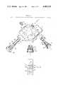
- FIG. 1is an exploded perspective view of the spray nozzle of the invention
- FIG. 2is a elevational sectional view of the nozzle
- FIG. 3is a side view of the nozzle assembly.
- the inventioncomprises an adjustable spray nozzle having interchangeable, small diameter orifice members.
- the spray nozzlehas a body 10 which has a cylindrical through bore 12 and a cylindrical bore 14 positioned at right angles to, and intersecting, the cylindrical through bore 12.
- Body 10also has an internal fluid passageway 16 which communicates between a intersecting cylindrical bore 18 and the cylindrical bore 14.
- Bore 18extends partially into body 10 and is internally threaded to receive mounting sleeve 20 which has an externally threaded neck 22 and, at its opposite end, an annular flange 24 whereby the nozzle can be mounted and secured to a conventional spray gun by a retainer nut (not shown).
- the cylindrical partial bore 18provides the fluid inlet port for the body 10.
- the through bore 12is counterbored at 26 and is internally threaded to receive the threaded neck 28 of a retainer sleeve 30.
- the retainer sleeve 30has an inner annular lip 32 to capture the distal flange 34 of splash pin 36.
- Splash pin 36is a cylindrical pin having beveled end surfaces 38 and 40, which are beveled at an angle from 25 degrees to 65 degrees, preferably at 45 degrees.
- the splash pin 36is also provided with two axial grooves 42 and 44.
- Body 10is also provided with a third bore 46 which extends from one edge surface thereof into intersection with the through bore 12 at an intermediate position along its length. Bore 46 is internally threaded to receive set screw 48 which has a distal neck 50. Neck 50 cooperates with either of the two axial grooves 42 and 44 of splash pin 40 to provide a key and keyway means whereby a predetermined angular orientation of the splash pin in bore 12 is maintained.
- the bore 14is counterbored at 52 and at 54 with successively greater diameter counterbores.
- Counterbore 54is internally threaded to receive the externally threaded neck 56 of the orifice member retainer plug 58.
- Orifice member 60is a generally cylindrical body having an arcuately concave discharge face 64, an inlet bore 62 on its opposite face which communicates with a small diameter orifice (not shown) in its discharge face.
- the arcuately concave face 64has a radius of curvature equal to the radius of the through bore 12 whereby the orifice member 60 can be positioned at the intersection of the through bore 12 and bore 14, lining the through bore 12.
- the orifice member retaining plug 58has a reduced-diameter, hollow stem 66 with a plurality of apertures 68 communicating with the interior of stem 66.
- the assembled nozzleis illustrated in FIG. 2.
- the splash pin 36is positioned in the through bore 12 with one of its beveled end surfaces (38) positioned opposite the small diameter orifice 68 of the orifice member 60.
- the orifice member 60is formed of a suitably hard, wear-resistant material such as tungsten carbide.
- the end of splash pin 36is also formed of a hard, wear-resistant material such as tungsten carbide and, for this purpose, the splash pin 36 has a reduced-diameter end portion 70 which receives a tungsten carbide sleeve 72 that is permanently affixed thereto.
- the tungsten carbide sleeve 72has the aforementioned beveled end surfaces 38 and 40.
- the splash pinis captured with its distal flange 34 secured within the retainer sleeve 30 by the inner annular lip 38 of the sleeve.
- the interior bore 74 of sleeve 30is internally threaded at 76 to receive a set screw 78, thereby permitting fixed adjustability in the axial spacing of the splash pin 36 in the through bore 12.
- the retainer sleeve 30is also provided with a knurled knob 80 for advancing and retracting the retainer sleeve 30 in its threaded engagement in the internally threaded counterbore 26.
- the splash pinis provided with a keyway such as axial grooves 42 and 44.
- Set screw 48is received in internally threaded bore 46 and neck 50 on the end of set screw 48 projects into one of either of these grooves 42 and 44, thus serving as a key and key way means to orient either of the beveled surfaces 38 and 40 to the orifice 68 of orifice member 60.
- the orifice member 60is secured by the retainer plug 58 which is threadably received in the internally threaded counterbore 54 of the bore 14.
- the retainer plug 58is provided with an annular groove at 82 to receive O-ring 84, thus sealing the interior annular chamber 86 which is formed between the second counterbore 52 of bore 12 and the reduced-diameter, hollow stem 66 of the retainer plug 58.
- the stem 66is open-ended, and discharges directly into the inlet bore 62 of the orifice member 60.
- the orifice member 60is sealed in bore 14 by sealing washer.
- the body 10is secured to a conventional spray gun barrel by the retainer nut 92 which has internal threads 94 to be received over the threaded end of a spray gun barrel.
- Sleeve 20is threadably engaged in the internally threaded bore 18 of body 10 and the interior of this sleeve communicates with the fluid passageway 16 that extends between bore 18 and counterbore 52 of body 10.
- FIG. 3there is illustrated a view in the direction indicated by arrowhead line 3--3' of FIG. 1.
- This viewshows the splash pin 36 with its beveled end surfaces 40 and 38, and shows the small diameter orifice 68 of the orifice member 60 directed upwardly against the lower beveled end surface 38 of pin 36.
- the spray nozzle assemblyis secured to the discharge barrel of a conventional spray gun and the retainer nut 92 is tightened thereon to seal the assembly. Since seal washer 96 has a low coefficient of friction, the nozzle can be rotated to change the orientation of the fan spray to the spray gun without loosening retainer nut 92.
- the liquid under high pressureis discharged from the spray gun barrel through the retainer sleeve 20 and into the inlet port of passageway 16, through passageway 16 into the annular chamber 86 surrounding the hollow stem 66 of the retainer plug 58.
- the liquidenters the hollow stem 66 through apertures 68 and passes through the orifice spray member.
- the liquidis discharged as an atomized jet through the small diameter orifice 68. This jet impinges upon the beveled surface 38 of splash and is deflected from the open end of the through bore in a fan-shaped spray.
- the volume of spray discharged and the area of the resultant fan-shaped sprayis regulated by the fixed adjustability of the position of the splash pin 36 in the assembly.
- the retraction of the splash pin 36opens the area of orifice 38, while the advance of the splash pin in the assembly closes or reduces the area of the orifice 68, directly controlling the volume of spray discharge from the assembly.
- the orifice member 60can be quickly interchanged with any of a plurality of orifice members having different diameter orifices 68, thereby greatly expanding the adjustable range of the nozzle. This can be accomplished without dismantling the spray nozzle assembly from the barrel of the spray gun or without disturbing the position of the splash pin.
- a substitute spray member having the same overall size and shape but, optionally, a different diameter orifice 68can be readily placed in bore 14 and the retainer plug 58 can be returned, sealing the assembly. This entire replacement can be accomplished in a few minutes, independently of any adjustment of the splash pin and without removing the spray nozzle assembly from the barrel of the spray gun.
Landscapes
- Nozzles (AREA)
Abstract
Description
Claims (17)
Priority Applications (1)
| Application Number | Priority Date | Filing Date | Title |
|---|---|---|---|
| US06/404,369US4465236A (en) | 1982-08-02 | 1982-08-02 | Adjustable spray nozzle |
Applications Claiming Priority (1)
| Application Number | Priority Date | Filing Date | Title |
|---|---|---|---|
| US06/404,369US4465236A (en) | 1982-08-02 | 1982-08-02 | Adjustable spray nozzle |
Publications (1)
| Publication Number | Publication Date |
|---|---|
| US4465236Atrue US4465236A (en) | 1984-08-14 |
Family
ID=23599329
Family Applications (1)
| Application Number | Title | Priority Date | Filing Date |
|---|---|---|---|
| US06/404,369Expired - LifetimeUS4465236A (en) | 1982-08-02 | 1982-08-02 | Adjustable spray nozzle |
Country Status (1)
| Country | Link |
|---|---|
| US (1) | US4465236A (en) |
Cited By (11)
| Publication number | Priority date | Publication date | Assignee | Title |
|---|---|---|---|---|
| US5319568A (en)* | 1991-07-30 | 1994-06-07 | Jesco Products Co., Inc. | Material dispensing system |
| US5762269A (en)* | 1996-05-14 | 1998-06-09 | Nelson Irrigation Corporation | Nozzle clip |
| US5765753A (en)* | 1996-07-18 | 1998-06-16 | Wagner Spray Tech Corporation | Reversible spray tip |
| US5887793A (en)* | 1997-06-09 | 1999-03-30 | Wagner Spray Tech Corporation | Dual mode reversible spray tip |
| US5893522A (en)* | 1997-06-02 | 1999-04-13 | Wagner Spray Tech Corporation | Method of orienting a spray tip in a holder |
| US5911364A (en)* | 1997-07-29 | 1999-06-15 | Wagner Spray Tech Corporation | Reversible tip detent |
| US6264115B1 (en) | 1999-09-29 | 2001-07-24 | Durotech Company | Airless reversible spray tip |
| US20090057592A1 (en)* | 2007-08-28 | 2009-03-05 | Lakhan Haresh C | Flow control and closure valve with axial flow in the valve element |
| US9284746B2 (en) | 2013-11-25 | 2016-03-15 | Edward S. Roberts, III | Insulated fence tensioner |
| US12090506B2 (en) | 2020-07-14 | 2024-09-17 | Techtronic Cordless Gp | Powered sprayer |
| CN119034967A (en)* | 2024-11-04 | 2024-11-29 | 南通普瑞特机械有限公司 | Electrostatic antirust spraying device for engine cylinder body and cylinder cover |
Citations (5)
| Publication number | Priority date | Publication date | Assignee | Title |
|---|---|---|---|---|
| US13366A (en)* | 1855-07-31 | Improved bucket for water-wheels | ||
| US3936002A (en)* | 1974-11-29 | 1976-02-03 | Geberth John Daniel Jun | Adjustable spray tip |
| US4126272A (en)* | 1976-02-20 | 1978-11-21 | Geberth John Daniel Jun | Adjustable spray tip |
| US4220286A (en)* | 1978-02-21 | 1980-09-02 | Geberth John Daniel Jun | Adjustable spray tip |
| US4269355A (en)* | 1979-03-19 | 1981-05-26 | Geberth John Daniel Jun | Self-cleaning spray nozzle |
- 1982
- 1982-08-02USUS06/404,369patent/US4465236A/ennot_activeExpired - Lifetime
Patent Citations (5)
| Publication number | Priority date | Publication date | Assignee | Title |
|---|---|---|---|---|
| US13366A (en)* | 1855-07-31 | Improved bucket for water-wheels | ||
| US3936002A (en)* | 1974-11-29 | 1976-02-03 | Geberth John Daniel Jun | Adjustable spray tip |
| US4126272A (en)* | 1976-02-20 | 1978-11-21 | Geberth John Daniel Jun | Adjustable spray tip |
| US4220286A (en)* | 1978-02-21 | 1980-09-02 | Geberth John Daniel Jun | Adjustable spray tip |
| US4269355A (en)* | 1979-03-19 | 1981-05-26 | Geberth John Daniel Jun | Self-cleaning spray nozzle |
Cited By (12)
| Publication number | Priority date | Publication date | Assignee | Title |
|---|---|---|---|---|
| US5319568A (en)* | 1991-07-30 | 1994-06-07 | Jesco Products Co., Inc. | Material dispensing system |
| US5762269A (en)* | 1996-05-14 | 1998-06-09 | Nelson Irrigation Corporation | Nozzle clip |
| US5765753A (en)* | 1996-07-18 | 1998-06-16 | Wagner Spray Tech Corporation | Reversible spray tip |
| US5893522A (en)* | 1997-06-02 | 1999-04-13 | Wagner Spray Tech Corporation | Method of orienting a spray tip in a holder |
| US5887793A (en)* | 1997-06-09 | 1999-03-30 | Wagner Spray Tech Corporation | Dual mode reversible spray tip |
| US5911364A (en)* | 1997-07-29 | 1999-06-15 | Wagner Spray Tech Corporation | Reversible tip detent |
| US6264115B1 (en) | 1999-09-29 | 2001-07-24 | Durotech Company | Airless reversible spray tip |
| US6390386B2 (en) | 1999-09-29 | 2002-05-21 | Durotech Company | Airless reversible spray tip |
| US20090057592A1 (en)* | 2007-08-28 | 2009-03-05 | Lakhan Haresh C | Flow control and closure valve with axial flow in the valve element |
| US9284746B2 (en) | 2013-11-25 | 2016-03-15 | Edward S. Roberts, III | Insulated fence tensioner |
| US12090506B2 (en) | 2020-07-14 | 2024-09-17 | Techtronic Cordless Gp | Powered sprayer |
| CN119034967A (en)* | 2024-11-04 | 2024-11-29 | 南通普瑞特机械有限公司 | Electrostatic antirust spraying device for engine cylinder body and cylinder cover |
Similar Documents
| Publication | Publication Date | Title |
|---|---|---|
| US4531675A (en) | Spray nozzle | |
| CA2066362C (en) | Baffle for hvlp paint spray gun | |
| US4465236A (en) | Adjustable spray nozzle | |
| US5102051A (en) | Spray gun | |
| US4993642A (en) | Paint spray gun | |
| US3936002A (en) | Adjustable spray tip | |
| CA1096909A (en) | Spray gun nozzle attachment | |
| US3633828A (en) | Spray gun | |
| DE3875608T2 (en) | CONTROL OF THE FLAT JET OF A SPRAY GUN. | |
| US5279461A (en) | Spray gun | |
| US3437274A (en) | Liquid spray apparatus | |
| CA2004257C (en) | Spray gun having a fanning air turbine mechanism | |
| US5255853A (en) | Adjustable fluid jet cleaner | |
| US4094468A (en) | Hand shower | |
| US4426040A (en) | Adjustable aerating shower head | |
| US4899938A (en) | Liquid spray nozzle adapter | |
| US3930619A (en) | Adjustable orifice spray gun | |
| US4461426A (en) | Adjustable aerial spray nozzle apparatus | |
| US4460519A (en) | Hydrotherapy jet unit | |
| US6918546B2 (en) | Reversible spray head | |
| US2172193A (en) | Device for spraying paint and the like and nozzle therefor | |
| EP0532742A1 (en) | Adjustable fluid jet cleaner. | |
| GB2088748A (en) | Replaceable nozzle for a spray gun | |
| US2539793A (en) | Adjustable sprinkler | |
| CA1038622A (en) | Spray gun |
Legal Events
| Date | Code | Title | Description |
|---|---|---|---|
| AS | Assignment | Owner name:PHYLLIS GRAHAM MAGNA CORPORATION BOX 5761 ORANGE C Free format text:ASSIGNMENT OF ASSIGNORS INTEREST.;ASSIGNOR:CALDER, OLIVER J.;REEL/FRAME:004239/0306 Effective date:19840106 | |
| STCF | Information on status: patent grant | Free format text:PATENTED CASE | |
| FPAY | Fee payment | Year of fee payment:4 | |
| AS | Assignment | Owner name:ASMACQUISITION CORPORATION, 1828 WEST SEQUOIA, ORA Free format text:ASSIGNMENT OF ASSIGNORS INTEREST.;ASSIGNOR:GRAHAM PHYLLIS DBA MAGNA CORPORATION;REEL/FRAME:005264/0470 Effective date:19891031 | |
| AS | Assignment | Owner name:BANK OF AMERICA NATIONAL TRUST AND SAVINGS ASSOCIA Free format text:SECURITY INTEREST;ASSIGNOR:ASMACQUISTION CORPORATION;REEL/FRAME:005360/0576 Effective date:19891001 | |
| FEPP | Fee payment procedure | Free format text:PAYOR NUMBER ASSIGNED (ORIGINAL EVENT CODE: ASPN); ENTITY STATUS OF PATENT OWNER: SMALL ENTITY | |
| FPAY | Fee payment | Year of fee payment:8 | |
| FPAY | Fee payment | Year of fee payment:12 | |
| AS | Assignment | Owner name:ASM COMPANY, INC., CALIFORNIA Free format text:TERMINATION OF SECURITY INTEREST AND RELEASE OF COLLATERAL;ASSIGNOR:BANK OF AMERICA NATIONAL TRUST AND SAVINGS ASSOCIATION;REEL/FRAME:008401/0079 Effective date:19970226 Owner name:HELLER FINANCIAL INC., ILLINOIS Free format text:CONTINUING SECURITY INTERST AND CONDITIONAL ASSIGNMENT OF PATENTS, TRADEMARKS COPYRIGHTS, AND LICENSES.;ASSIGNOR:ASM COMPANY, INC.;REEL/FRAME:008382/0357 Effective date:19970227 | |
| AS | Assignment | Owner name:FLEET CAPITAL CORPORATION,AS ADMINISTRATIVE AGENT, Free format text:ASSIGNMENT OF ASSIGNORS INTEREST;ASSIGNOR:ASM COMPANY, INC;REEL/FRAME:010078/0911 Effective date:19990608 Owner name:FLEET CAPITAL CORPORATION, AS ADMINISTRATIVE AGENT Free format text:SECURITY INTEREST;ASSIGNOR:HELLER FINANCIAL, INC., AS AGENT;REEL/FRAME:010078/0891 Effective date:19990608 | |
| FEPP | Fee payment procedure | Free format text:PAYOR NUMBER ASSIGNED (ORIGINAL EVENT CODE: ASPN); ENTITY STATUS OF PATENT OWNER: SMALL ENTITY Free format text:PAYER NUMBER DE-ASSIGNED (ORIGINAL EVENT CODE: RMPN); ENTITY STATUS OF PATENT OWNER: SMALL ENTITY | |
| AS | Assignment | Owner name:FLEET CAPITAL CORPORATION, AS A LENDER AND AS ADMI Free format text:SECURITY AGREEMENT REAFFIRMATION AND AMENDMENT;ASSIGNOR:ASM COMPANY, INC., A CORP. OF CALIFORNIA;REEL/FRAME:010437/0029 Effective date:19991116 | |
| AS | Assignment | Owner name:FLEET CAPITAL CORPORATION, AS ADMINISTRATIVE AGENT Free format text:SECURITY AGREEMENT;ASSIGNOR:ASM COMPANY, INC.;REEL/FRAME:010531/0990 Effective date:19990608 | |
| AS | Assignment | Owner name:ASM COMPANY INC., CALIFORNIA Free format text:RELEASE BY SECURED PARTY;ASSIGNOR:FLEET CAPITAL CORPORATION, AS ADMINISTRATIVE AGENT;REEL/FRAME:013691/0488 Effective date:20030122 |