US4463765A - Screw-in pacing lead assembly - Google Patents
Screw-in pacing lead assemblyDownload PDFInfo
- Publication number
- US4463765A US4463765AUS06/412,425US41242582AUS4463765AUS 4463765 AUS4463765 AUS 4463765AUS 41242582 AUS41242582 AUS 41242582AUS 4463765 AUS4463765 AUS 4463765A
- Authority
- US
- United States
- Prior art keywords
- lead
- proximal end
- distal end
- tubular body
- assembly
- Prior art date
- Legal status (The legal status is an assumption and is not a legal conclusion. Google has not performed a legal analysis and makes no representation as to the accuracy of the status listed.)
- Expired - Lifetime
Links
- 239000004020conductorSubstances0.000claimsabstractdescription42
- 239000002184metalSubstances0.000claimsabstractdescription28
- 239000000463materialSubstances0.000claimsabstractdescription15
- 239000012530fluidSubstances0.000claimsdescription6
- 230000008878couplingEffects0.000claimsdescription5
- 238000010168coupling processMethods0.000claimsdescription5
- 238000005859coupling reactionMethods0.000claimsdescription5
- 239000011810insulating materialSubstances0.000claimsdescription5
- 229920000260silasticPolymers0.000claimsdescription4
- 210000001124body fluidAnatomy0.000claimsdescription2
- 239000010839body fluidSubstances0.000claimsdescription2
- 238000007789sealingMethods0.000claimsdescription2
- 230000015572biosynthetic processEffects0.000claims1
- 230000007246mechanismEffects0.000abstractdescription6
- 210000002837heart atriumAnatomy0.000description10
- 208000027418Wounds and injuryDiseases0.000description6
- 230000000712assemblyEffects0.000description5
- 238000000429assemblyMethods0.000description5
- 210000001174endocardiumAnatomy0.000description4
- 210000003462veinAnatomy0.000description4
- 238000010276constructionMethods0.000description3
- 230000001605fetal effectEffects0.000description3
- 230000013011matingEffects0.000description3
- 238000012544monitoring processMethods0.000description3
- 210000001215vaginaAnatomy0.000description2
- 210000003679cervix uteriAnatomy0.000description1
- 238000002788crimpingMethods0.000description1
- 230000009977dual effectEffects0.000description1
- 208000014674injuryDiseases0.000description1
- 238000003780insertionMethods0.000description1
- 230000037431insertionEffects0.000description1
- 238000012986modificationMethods0.000description1
- 230000004048modificationEffects0.000description1
- 230000000638stimulationEffects0.000description1
- 230000008733traumaEffects0.000description1
Images
Classifications
- A—HUMAN NECESSITIES
- A61—MEDICAL OR VETERINARY SCIENCE; HYGIENE
- A61N—ELECTROTHERAPY; MAGNETOTHERAPY; RADIATION THERAPY; ULTRASOUND THERAPY
- A61N1/00—Electrotherapy; Circuits therefor
- A61N1/02—Details
- A61N1/04—Electrodes
- A61N1/05—Electrodes for implantation or insertion into the body, e.g. heart electrode
- A61N1/056—Transvascular endocardial electrode systems
- A61N1/057—Anchoring means; Means for fixing the head inside the heart
- A61N1/0573—Anchoring means; Means for fixing the head inside the heart chacterised by means penetrating the heart tissue, e.g. helix needle or hook
Definitions
- the present inventionrelates to pacing lead assemblies and more particularly to a screw-in pacing lead assembly having a corkscrew shaped securing device at the distal end thereof which is adapted to be threaded into living tissue for securing an electrode assembly at the distal end of the pacing lead to the living tissue such as to the endocardium in a ventricle or atrium of the heart.
- Pacing lead assemblieshave been in use for a number of years for supplying electrical stimulation pulses to or for receiving electrical pulses from living tissue.
- Such pacing lead assemblieshave included a pacing lead comprising single or multiconductor coils of insulated wire having an insulating sheath thereabout with the lumen or cylindrical envelope defined by the coiled wire providing a space into which a stiffening stylet can be inserted.
- the conductive coilis connected to an electrode in an electrode assembly at the distal end of the pacing lead and typically a terminal member is mounted within a flexure sleeve at the proximal end of the pacing lead assembly and connected to the proximal end of the conductive coil.
- a styletis inserted into the pacing lead to provide stiffening of same when it is inserted into a vein for positioning the lead in living tissue such as in the endocardium in the ventricle or atrium of the heart or proximate thereto.
- One such means for securing the electrode assembly in placeis a corkscrew (or helical) shaped securing device which is mounted at the distal end of the pacing lead assembly.
- a proximal end of the corkscrew shaped securing deviceis fixed in a mounting member and the outer end thereof is adapted to be screwed into living tissue.
- a stylet with a specially configured distal endsuch as a screwdriver shaped end, is adapted to be received in a mating slot in the rear end of the mounting member. Then the proximal end of the stylet is rotated within the pacing lead to cause the corkscrew shaped securing device to advance into living tissue.
- This type of pacing lead assemblyrequires a stylet with a specially configured head. Also in this type of pacing lead assembly the stylet must be inserted all the way to the distal end of the pacing lead, properly located within a mating slot and then rotated to cause the corkscrew shaped securing device to be screwed into living tissue.
- the screwdriver shaped head at the distal end of the stylethas sharp edges which can damage the multiconductor coil in the lead as the stylet is moved through the coil.
- the head of the styletalso can catch on a turn of the coil and pierce through the insulating sheath.
- such a screw-in pacing lead assemblyrequires that the distal end of the stylet be firmly located within a slot in the mounting member mounting the corkscrew shaped securing device. This is sometimes difficult to do and a physician manipulating the proximal end of the style is not always certain that he has effectively engaged the screwdriver shaped head of the stylet with the slot in the mounting member thereby to screw the corkscrew shaped securing device into living tissue.
- the screw-in pacing lead assembly of the present inventionprovides a drive means receivable within a conventional pacing lead and fixed at the distal end thereof to a mounting member mounting a corkscrew shaped securing device and at its proximal end to a drive member.
- the drive mechanismdefines a cylindrical envelope or lumen through which a stylet can be inserted for stiffening of the pacing lead when required but which stylet is not utilized in rotating the corkscrew shaped securing device into living tissue and which stylet can have a rounded distal end to facilitate insertion thereof into and through a pacing lead.
- a body-implantable lead assemblycomprising a lead having a proximal end and a distal end, said proximal end being adapted to be connected to electrical means for supplying or receiving electrical pulses, said distal end being adapted to be connected to tissue of a living body, said lead comprising a sheath of material inert to body materials or fluids and at least one wire conductor having a proximal end and a distal end and extending from said proximal end of said lead within said sheath to said distal end of said lead, a terminal structure electrically coupled to said proximal end of said wire conductor and adapted to couple electrically said proximal end of said wire conductor to the electrical means, an electrode assembly including an electrode, said distal end of said wire conductor being electrically connected to said electrode, said electrode including a tubular body which has a proximal end and a distal end and said sheath being coupled to said proximal end of said tubular
- a body-implantable lead assemblycomprising a lead having a proximal end and a distal end, said proximal end being adapted to be connected to electrical means for supplying or receiving electrical pulses, said distal end being adapted to be connected to tissue of a living body, said lead comprising a sheath of material inert to body materials or fluids and at least one wire conductor having a proximal end and a distal end and extending from said proximal end of said lead within said sheath to said distal end of said lead, a terminal structure electrically coupling to said proximal end of said wire conductor and adapted to couple electrically said proximal end of said wire conductor to the electrical means, an electrode assembly including an electrode, said distal end of said wire conductor being electrically connected to said electrode, said electrode including a tubular body which has a proximal end and a distal end and said sheath being coupled to said proximal end of
- a body-implantable lead assemblycomprising a lead having a proximal end and a distal end, said proximal end being adapted to be connected to electrical means for supplying or receiving electrical pulses, said distal end being adapted to be connected to tissue of a living body, said lead comprising a sheath made of materials inert to body materials and fluids and at least one wire conductor having a proximal end and a distal end and extending from said proximal end of said lead within said sheath to said distal end of said lead, a terminal structure electrically said proximal end of said wire conductor and adapted to couple electrically said proximal end of said wire conductor to the electrical means, an electrode assembly including an electrode, said distal end of said wire conductor being electrically connected to said electrode, said electrode including a tubular body which has a proximal end and a distal end and said sheath being coupled to said proximal end of said
- the drive meansis preferably a helical metal ribbon fixed to the mounting member at the distal end thereof and to the drive member at the proximal end thereof.
- the drive memberis made of metal and serves a dual function as the terminal pin for the pacing lead assembly.
- Such drive meansmay also be rotated in a counterclockwise direction to retract the securing device from living tissue if the lead needs to be removed or repositioned.
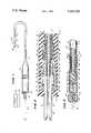
- FIG. 1is a plan view of the pacing lead assembly 10 of the present invention with portions of the pacing lead cut away and with the distal end of the stylet positioned to be inserted into the proximal end of the pacing lead assembly.
- FIG. 2is an enlarged sectional view of the flexure sleeve at the proximal end of the pacing lead assembly shown in FIG. 1.
- FIG. 3is an enlarged sectional view of an electrode assembly at the distal end of the pacing lead assembly shown in FIG. 1.
- FIG. 1a screw-in pacing lead assembly 10 constructed in accordance with the teachings of the present invention and including a pacing lead 12, a flexure sleeve 14 at the proximal end 15 thereof and an electrode assembly 16 at the distal end 17 thereof.
- a terminal housing 18(FIG. 2) which is electrically connected in turn to a terminal pin/drive member 19 that is connected to a pulse generator 20 by an electrical connection shown schematically as a conductor 22 in FIG. 1.
- the whole assembly 10is referred to as the "pacing lead".
- the term “pacing lead assembly”is used since such assembly 10 includes not only the lead or lead body 12 but also the flexure sleeve 14 and the electrode assembly 16.
- the electrode assembly 16includes a corkscrew shaped securing device 24 which extends from distal end 25 of the electrode assembly 16.
- terminal pin/drive member 19Extending from the proximal end 26 of the flexure sleeve 14 is terminal pin/drive member 19 which is constructed and operated in accordance with the teachings of the present invention for rotating the corkscrew device 24 into or out of living tissue after the electrode assembly 16 has been placed near living tissue such as adjacent the endocardium in a ventricle or atrium of the heart.
- a stylet 29can be inserted through the terminal pin/drive member 18 for positioning the electrode assembly 16 in a ventricle or atrium and/or for stiffening the pacing lead 12 before or after the pacing lead 12 with the electrode assembly 16 at the distal end thereof has been inserted into a body such as into a ventricle or atrium of the heart.
- the stylet 29is not used for rotating the corkscrew securing device 24 and is used only for stiffening the lead 12 and/or for positioning the electrode assembly 16 in a ventricle or atrium.
- a preformed or a preshaped "J" type styletcan be provided in the lead 12 for facilitating placement and attachment of the electrode assembly 16 in the atrium.
- the flexure sleeve 14has an inner cylindrical cavity 30 machined therein in which is received the cylindrical terminal housing 18.
- the lead 12includes one or more filars or wire conductors 32 coiled in a coil 34 and surrounded by a sheath 36.
- the proximal end 15 of the lead 12extends into the flexure sleeve 14 and through a cylindrical passageway 38 therein to the cylindrical cavity 30 where proximal end 39 of the sheath 36 is separated from the coil 34 and is received around a forward end portion 40 of the cylindrical terminal housing 18.
- a crimping sleeve 42is received in the end portion 40 and a bare proximal end portion 44 of the conductor or filar 32 is coiled around the sleeve 42 and the end portion 40 crimped thereover.
- the coil 34consists of two or more coiled wire conductors 32 of small diameter connected in parallel between the ends thereof. Such parallel connection is effected by the respective coiling of the bare end of the conductors 32 about sleeve 42 at the proximal end thereof and about a sleeve (sleeve 108 in FIG. 3) at the distal ends thereof.
- a drive mechanism 48which is in the form of a flat helically wound metal ribbon 48.
- the helical ribbon 48extends through the coil 34 of the lead 12 between a cavity 50 within the cylindrical terminal housing 18 and the electrode assembly 16.
- the terminal pin/drive member 19is generally cylindrical in shape and has an axial passageway 60 therethrough opening at its forward end into the cavity 50 in the cylindrical terminal housing 18 and at its rearward end onto the ambient environment before it is inserted into a pulse generator 20.
- a counterbore 62which is larger than and coaxial with the axial passageway 60 and into which is received proximal end 64 of the helical flat metal ribbon 48. This proximal end 64 of the helical metal ribbon 48 is fixed within the counterbore 62 and around a sleeve 65.
- the generally cylindrical terminal pin/drive member 19has an annular boss 68 intermediate the ends thereof and closer to the forward end portion 56 thereof so as to be received within the cavity 50.
- the annular boss 68has a rearward facing shoulder 70 and a forward facing shoulder 72.
- a metallic spring washer 74is positioned between the forward facing shoulder 72 and a shoulder 76 formed in the cavity 50 within the cylindrical terminal housing 18 to provide electrical contact therebetween.
- a metal ring 80Between the inner surface of the end wall 64 of the flexure sleeve 54 and the annular boss 68 is positioned a metal ring 80.
- a second metallic spring washer 84is positioned between the ring 80 and the rearward facing shoulder 70 on the annular boss 68.
- the washers 74 and 84serve as thrust washers and/or bearing means for facilitating rotation of the terminal pin/drive member 19 and for establishing an electrical connection to the coil 34 from the terminal pin 19.
- rear end portion 86 of the terminal pin/drive member 19 extending from the flexure sleeve 14can be adapted for connection to a fixture to facilitate rotation of the terminal pin/drive member 19.
- the drive mechanismconsisting of the helically wound flat metal ribbon 48 extends to the electrode assembly 16 and is received in proximal end 87 of a metal tubular body 88 of the electrode assembly 16.
- a generally cylindrical non-conductive mounting member 90having elastomeric (silastic) cushions 91 and 92 at the ends thereof.
- Distal end 94 of the helically wound flat metal ribbon 48is secured within the proximal end of the mounting member 90 while proximal end 96 of the corkscrew shaped securing device 24 is received in the distal end of the mounting member 90.
- the tubular body 88has a smooth, porous-surfaced, annular cap-shaped electrode 98 which can be made of sintered metal and which is fixed to and integral with the distal end of tubular body 88.
- a plug 100Fixed within the distal end of the tubular body 88 is a plug 100 having a helical or spiral passageway 102 therethrough through which the corkscrew securing device 24 is received.
- a sealing disc 103 made of silastic materialis fixed to the inner end of plug 100 for preventing intrusion of body fluids into the tubular body 88.
- a distal end 104 of the sheath 36extends over the metal tubular body 88 and to the annular cap-shaped electrode 98 thereof.
- a bare end portion 106 of the coiled wire conductor(s) 32is coiled about a sleeve 108 received within proximal end 87 of the tubular body 88 such that the outer surface of the coil is in intimate contact with the interior surface of the distal end of the metal tubular body 88 and in good electrical contact therewith.
- the sleeve 108has a shoulder at the distal end 109 thereof which limits inward movement of the bared coiled wire conductor end portion 105 and which serves as a backstop for block 90, namely for the silastic cushion 91.
- the helical metal ribbon 48is received through the insulating sleeve 108 for mounting in the mounting member 90.
- the terminal pin/drive member 19can be rotated to cause rotation of the helical metal ribbon 48 which in turn rotates the mounting member 90.
- Such rotation of the mounting member 90causes the corkscrew shaped securing device 24 to be rotated or threaded within the spiral or helical passageway 102 in the plug 100 which acts as a nut thereby causing the corkscrew shaped securing device 24 to be moved axially in or out of the tubular body 88 or the electrode assembly 16.
- the corkscrew shaped securing device 24can be screwed into living tissue to anchor the electrode assembly 16 in the living tissue such as the endocardium in the ventricle or atrium of a heart.
- the lumen or cylindrical envelope defined by and within the helically wound metal ribbon 48enables a stylet 29 to be inserted within the lead 12 and more particularly within the lumen or cylindrical envelope of the helically wound metal ribbon 48 for stiffening the lead 12 when it is inserted into a body, such as into a vein, and/or for positioning the electrode assembly 16 in the ventricle or atrium.
- the stylet 29is not needed for rotating the corkscrew shaped securing device 24 into living tissue and can have a rounded tip. Further it will be appreciated that the terminal pin/drive member 19 can be rotated with or without a stylet 29 passing therethrough into the lead 12.
- the construction of the screw-in pacing lead assembly 10 of the present invention described aboveprovides a simple means for rotating the corkscrew shaped securing device 24 into or out of living tissue and with or without a stylet 29 received in the lead 12.
- the distal end of the stylet 29need not be configured with a special drive configuration such as a screwdriver head for being received in a mating head in the end of a mounting member such as mounting member 90.
- Thisenables the use of a rounded distal end stylet 29 which minimizes catching of the end of the stylet 29 on turns of the coil 34 and/or piercing through the sheath 26 of the lead 12.
- a physician rotating the terminal pin/drive member 19can be certain that the corkscrew shaped securing device 24 is being moved into or out of living tissue.
- drive mechanism 48is used in a J-atrial pacing lead, with or without a stylet therein.
- rotation of the drive mechanism, namely ribbon 48is achieved notwithstanding the U-shaped bight of the J shaped distal end and without twisting or bowing out of the lead 12.
- the stylet 29can be used for stiffening and/or positioning the electrode assembly 16 in an atrium.
- the screw-in pacing lead assembly 10 of the present inventionhas a number of advantages, some of which have been described above and others of which are inherent in the invention. Also it will be apparent to those skilled in the art that modifications can be made to the screw-in pacing lead assembly 10 of the present invention without departing from the teachings of the present invention.
- the mounting member 90 and plug 100being made of insulating material
- the corkscrew shaped securing device 24is insulated from the electrode 98.
- this constructionwith the mounting member 90 and plug 100 being made of insulating materials, facilitates use of the screw-in pacing lead assembly 10 with bipolar or multielectrode assemblies in place of the unipolar electrode assembly 16. Accordingly, the scope of the invention is only to be limited as necessitated by the accompanying claims.
Landscapes
- Health & Medical Sciences (AREA)
- Cardiology (AREA)
- Heart & Thoracic Surgery (AREA)
- Vascular Medicine (AREA)
- Engineering & Computer Science (AREA)
- Biomedical Technology (AREA)
- Nuclear Medicine, Radiotherapy & Molecular Imaging (AREA)
- Radiology & Medical Imaging (AREA)
- Life Sciences & Earth Sciences (AREA)
- Animal Behavior & Ethology (AREA)
- General Health & Medical Sciences (AREA)
- Public Health (AREA)
- Veterinary Medicine (AREA)
- Electrotherapy Devices (AREA)
Abstract
Description
Claims (19)
Priority Applications (1)
| Application Number | Priority Date | Filing Date | Title |
|---|---|---|---|
| US06/412,425US4463765A (en) | 1982-08-30 | 1982-08-30 | Screw-in pacing lead assembly |
Applications Claiming Priority (1)
| Application Number | Priority Date | Filing Date | Title |
|---|---|---|---|
| US06/412,425US4463765A (en) | 1982-08-30 | 1982-08-30 | Screw-in pacing lead assembly |
Publications (1)
| Publication Number | Publication Date |
|---|---|
| US4463765Atrue US4463765A (en) | 1984-08-07 |
Family
ID=23632917
Family Applications (1)
| Application Number | Title | Priority Date | Filing Date |
|---|---|---|---|
| US06/412,425Expired - LifetimeUS4463765A (en) | 1982-08-30 | 1982-08-30 | Screw-in pacing lead assembly |
Country Status (1)
| Country | Link |
|---|---|
| US (1) | US4463765A (en) |
Cited By (50)
| Publication number | Priority date | Publication date | Assignee | Title |
|---|---|---|---|---|
| US4538623A (en)* | 1984-04-09 | 1985-09-03 | Medtronic, Inc. | Thread electrode assembly |
| US4570642A (en)* | 1983-09-23 | 1986-02-18 | Daig Corporation | Endocardial extendable screw-in lead |
| US4577643A (en)* | 1984-05-10 | 1986-03-25 | Cordis Corporation | Movable multi-contact electromechanical connection |
| US4628943A (en)* | 1985-06-21 | 1986-12-16 | Cordis Corporation | Bipolar screw-in packing lead assembly |
| US4649938A (en)* | 1985-04-29 | 1987-03-17 | Mcarthur William A | Tissue-stimulating electrode having sealed, low-friction extendable/retractable active fixation means |
| US4662382A (en)* | 1985-01-16 | 1987-05-05 | Intermedics, Inc. | Pacemaker lead with enhanced sensitivity |
| US4667686A (en)* | 1985-05-16 | 1987-05-26 | Cordis Corporation | Pacer lead terminal assembly |
| US4827940A (en)* | 1987-04-13 | 1989-05-09 | Cardiac Pacemakers, Inc. | Soluble covering for cardiac pacing electrode |
| US4951687A (en)* | 1989-01-31 | 1990-08-28 | Medtronic, Inc. | Medical electrical lead connector |
| US5056516A (en)* | 1989-11-02 | 1991-10-15 | Intermedics, Inc. | Implantable endocordial lead with torque-transmitting lanyard |
| US5228455A (en)* | 1991-05-20 | 1993-07-20 | Siemens Pacesetter, Inc. | Implant tool for extendable/retractable positive fixation lead |
| EP0570712A1 (en)* | 1992-05-21 | 1993-11-24 | Pacesetter AB | Electrode arrangement |
| US5354327A (en)* | 1993-04-07 | 1994-10-11 | Medtronic, Inc. | Conductor coil with specific ratio of torque to bending stiffness |
| US5456708A (en)* | 1993-10-28 | 1995-10-10 | Pacesetter, Inc. | Rotatable pin, screw-in pacing and sensing lead having improved tip and fluidic seal |
| US5456707A (en)* | 1993-10-22 | 1995-10-10 | Vitatron Medical Bv | Pacing lead with improved torsion characteristics |
| US5487758A (en)* | 1992-09-28 | 1996-01-30 | Siemens-Elema Ab | Electrode system for pacemakers |
| US5569883A (en)* | 1994-08-31 | 1996-10-29 | Pacesetter, Inc. | Joint for providing a secure connection between a wound element and a mating part in a body implantable lead assembly and method for making such joint |
| US5716390A (en)* | 1996-08-09 | 1998-02-10 | Pacesetter, Inc. | Reduced diameter active fixation pacing lead using concentric interleaved coils |
| US5876398A (en)* | 1994-09-08 | 1999-03-02 | Medtronic, Inc. | Method and apparatus for R-F ablation |
| US5913887A (en)* | 1996-03-01 | 1999-06-22 | Cardiac Pacemakers, Inc. | Device for the transvenous cardioversion of atrial fibrillation or atrial flutter including three coil electrodes |
| US5916243A (en)* | 1992-11-24 | 1999-06-29 | Cardiac Pacemakers, Inc. | Implantable conformal coil patch electrode with multiple conductive elements for cardioversion and defibrillation |
| US6085119A (en)* | 1998-07-22 | 2000-07-04 | Cardiac Pacemakers, Inc. | Single pass endocardial lead for multi-site atrial pacing |
| US6097986A (en)* | 1997-12-17 | 2000-08-01 | Cardiac Pacemakers, Inc. | Retractable lead with mesh screen |
| US6108582A (en)* | 1998-07-02 | 2000-08-22 | Intermedics Inc. | Cardiac pacemaker lead with extendable/retractable fixation |
| US6152954A (en)* | 1998-07-22 | 2000-11-28 | Cardiac Pacemakers, Inc. | Single pass lead having retractable, actively attached electrode for pacing and sensing |
| US6212434B1 (en) | 1998-07-22 | 2001-04-03 | Cardiac Pacemakers, Inc. | Single pass lead system |
| US6321122B1 (en) | 1998-07-22 | 2001-11-20 | Cardiac Pacemakers, Inc. | Single pass defibrillation/pacing lead with passively attached electrode for pacing and sensing |
| US6463334B1 (en) | 1998-11-02 | 2002-10-08 | Cardiac Pacemakers, Inc. | Extendable and retractable lead |
| US6501994B1 (en) | 1997-12-24 | 2002-12-31 | Cardiac Pacemakers, Inc. | High impedance electrode tip |
| US6501990B1 (en) | 1999-12-23 | 2002-12-31 | Cardiac Pacemakers, Inc. | Extendable and retractable lead having a snap-fit terminal connector |
| US20050085886A1 (en)* | 2003-10-17 | 2005-04-21 | Medtronic, Inc. | Medical lead fixation |
| US20050246007A1 (en)* | 2004-04-28 | 2005-11-03 | Medtronic, Inc. | Novel lead body assemblies |
| US7245973B2 (en) | 2003-12-23 | 2007-07-17 | Cardiac Pacemakers, Inc. | His bundle mapping, pacing, and injection lead |
| US20070179582A1 (en)* | 2006-01-31 | 2007-08-02 | Marshall Mark T | Polymer reinforced coil conductor for torque transmission |
| US20090234368A1 (en)* | 2008-03-17 | 2009-09-17 | Brian Gore | Low profile medical devices with internal drive shafts that cooperate with releasably engageable drive tools and related methods |
| WO2010114433A1 (en)* | 2009-03-31 | 2010-10-07 | St. Jude Medical Ab | An implantable mri compatible medical lead with a rotatable control member |
| US20100262213A1 (en)* | 2007-11-14 | 2010-10-14 | Rolf Hill | method of producing a proximal connector end of an implantable lead |
| US7840283B1 (en) | 2006-09-21 | 2010-11-23 | Pacesetter, Inc. | Bipolar screw-in lead |
| US20100331937A1 (en)* | 2009-06-30 | 2010-12-30 | Foster Arthur J | Active fixation lead with helix securement mechanism |
| US8285376B2 (en) | 2004-12-20 | 2012-10-09 | Cardiac Pacemakers, Inc. | Ventricular pacing |
| US8290586B2 (en) | 2004-12-20 | 2012-10-16 | Cardiac Pacemakers, Inc. | Methods, devices and systems for single-chamber pacing using a dual-chamber pacing device |
| US8326423B2 (en) | 2004-12-20 | 2012-12-04 | Cardiac Pacemakers, Inc. | Devices and methods for steering electrical stimulation in cardiac rhythm management |
| US8423139B2 (en) | 2004-12-20 | 2013-04-16 | Cardiac Pacemakers, Inc. | Methods, devices and systems for cardiac rhythm management using an electrode arrangement |
| US20130102858A1 (en)* | 2010-06-18 | 2013-04-25 | St. Jude Medical Ab | Implantable sensor device and system |
| US8538521B2 (en) | 2004-12-20 | 2013-09-17 | Cardiac Pacemakers, Inc. | Systems, devices and methods for monitoring efficiency of pacing |
| US8543203B2 (en) | 2004-12-20 | 2013-09-24 | Cardiac Pacemakers, Inc. | Endocardial pacing devices and methods useful for resynchronization and defibrillation |
| US8565880B2 (en) | 2010-04-27 | 2013-10-22 | Cardiac Pacemakers, Inc. | His-bundle capture verification and monitoring |
| US8688234B2 (en) | 2008-12-19 | 2014-04-01 | Cardiac Pacemakers, Inc. | Devices, methods, and systems including cardiac pacing |
| US8880169B2 (en) | 2004-12-20 | 2014-11-04 | Cardiac Pacemakers, Inc. | Endocardial pacing relating to conduction abnormalities |
| US20150151116A1 (en)* | 2009-11-30 | 2015-06-04 | Sorin Crm Sas | Kit for penetrating the cardiac septum and for implantation of a transeptal lead, including a lead for detection/stimulation of a left heart cavity |
Citations (6)
| Publication number | Priority date | Publication date | Assignee | Title |
|---|---|---|---|---|
| US4106512A (en)* | 1976-12-16 | 1978-08-15 | Medtronic, Inc. | Transvenously implantable lead |
| DE2806069A1 (en)* | 1978-02-14 | 1979-08-16 | Hubert Kraemer | Endocardiac stimulation electrode for pacemaker - has helical wire coil enclosed in pliable plastics envelope with stimulator |
| US4217913A (en)* | 1977-10-10 | 1980-08-19 | Medtronic, Inc. | Body-implantable lead with protected, extendable tissue securing means |
| US4311153A (en)* | 1980-09-30 | 1982-01-19 | Medtronic, Inc. | Screw-in lead having lead tip with membrane |
| US4381013A (en)* | 1981-03-19 | 1983-04-26 | Medtronic, Inc. | "J" Stylet wire |
| US4402330A (en)* | 1979-09-24 | 1983-09-06 | Medtronic, Inc. | Body implantable lead |
- 1982
- 1982-08-30USUS06/412,425patent/US4463765A/ennot_activeExpired - Lifetime
Patent Citations (6)
| Publication number | Priority date | Publication date | Assignee | Title |
|---|---|---|---|---|
| US4106512A (en)* | 1976-12-16 | 1978-08-15 | Medtronic, Inc. | Transvenously implantable lead |
| US4217913A (en)* | 1977-10-10 | 1980-08-19 | Medtronic, Inc. | Body-implantable lead with protected, extendable tissue securing means |
| DE2806069A1 (en)* | 1978-02-14 | 1979-08-16 | Hubert Kraemer | Endocardiac stimulation electrode for pacemaker - has helical wire coil enclosed in pliable plastics envelope with stimulator |
| US4402330A (en)* | 1979-09-24 | 1983-09-06 | Medtronic, Inc. | Body implantable lead |
| US4311153A (en)* | 1980-09-30 | 1982-01-19 | Medtronic, Inc. | Screw-in lead having lead tip with membrane |
| US4381013A (en)* | 1981-03-19 | 1983-04-26 | Medtronic, Inc. | "J" Stylet wire |
Cited By (92)
| Publication number | Priority date | Publication date | Assignee | Title |
|---|---|---|---|---|
| US4570642A (en)* | 1983-09-23 | 1986-02-18 | Daig Corporation | Endocardial extendable screw-in lead |
| US4538623A (en)* | 1984-04-09 | 1985-09-03 | Medtronic, Inc. | Thread electrode assembly |
| US4577643A (en)* | 1984-05-10 | 1986-03-25 | Cordis Corporation | Movable multi-contact electromechanical connection |
| US4662382A (en)* | 1985-01-16 | 1987-05-05 | Intermedics, Inc. | Pacemaker lead with enhanced sensitivity |
| US4649938A (en)* | 1985-04-29 | 1987-03-17 | Mcarthur William A | Tissue-stimulating electrode having sealed, low-friction extendable/retractable active fixation means |
| US4667686A (en)* | 1985-05-16 | 1987-05-26 | Cordis Corporation | Pacer lead terminal assembly |
| US4628943A (en)* | 1985-06-21 | 1986-12-16 | Cordis Corporation | Bipolar screw-in packing lead assembly |
| US4827940A (en)* | 1987-04-13 | 1989-05-09 | Cardiac Pacemakers, Inc. | Soluble covering for cardiac pacing electrode |
| US4951687A (en)* | 1989-01-31 | 1990-08-28 | Medtronic, Inc. | Medical electrical lead connector |
| US5056516A (en)* | 1989-11-02 | 1991-10-15 | Intermedics, Inc. | Implantable endocordial lead with torque-transmitting lanyard |
| US5228455A (en)* | 1991-05-20 | 1993-07-20 | Siemens Pacesetter, Inc. | Implant tool for extendable/retractable positive fixation lead |
| EP0570712A1 (en)* | 1992-05-21 | 1993-11-24 | Pacesetter AB | Electrode arrangement |
| US5342413A (en)* | 1992-05-21 | 1994-08-30 | Siemens-Elema Ab | Medical electrode arrangement |
| US5487758A (en)* | 1992-09-28 | 1996-01-30 | Siemens-Elema Ab | Electrode system for pacemakers |
| US6038483A (en)* | 1992-11-24 | 2000-03-14 | Cardiac Pacemakers, Inc. | Implantable conformal coil patch electrode with multiple conductive elements for cardioversion and defibrillation |
| US6152955A (en)* | 1992-11-24 | 2000-11-28 | Cardiac Pacemakers, Inc. | Implantable conformal coil patch electrode with multiple conductive elements for cardioversion and defibrillation |
| US5916243A (en)* | 1992-11-24 | 1999-06-29 | Cardiac Pacemakers, Inc. | Implantable conformal coil patch electrode with multiple conductive elements for cardioversion and defibrillation |
| US6026332A (en)* | 1992-11-24 | 2000-02-15 | Cardiac Pacemakers, Inc. | Implantable conformal coil patch electrode with multiple conductive elements for cardioversion and defibrillation |
| US6032079A (en)* | 1992-11-24 | 2000-02-29 | Cardiac Pacemakers, Inc. | Implantable conformal coil electrode with multiple conductive elements for cardioversion and defibrillation |
| US5354327A (en)* | 1993-04-07 | 1994-10-11 | Medtronic, Inc. | Conductor coil with specific ratio of torque to bending stiffness |
| US5456707A (en)* | 1993-10-22 | 1995-10-10 | Vitatron Medical Bv | Pacing lead with improved torsion characteristics |
| US5456708A (en)* | 1993-10-28 | 1995-10-10 | Pacesetter, Inc. | Rotatable pin, screw-in pacing and sensing lead having improved tip and fluidic seal |
| US5569883A (en)* | 1994-08-31 | 1996-10-29 | Pacesetter, Inc. | Joint for providing a secure connection between a wound element and a mating part in a body implantable lead assembly and method for making such joint |
| US5876398A (en)* | 1994-09-08 | 1999-03-02 | Medtronic, Inc. | Method and apparatus for R-F ablation |
| US6741894B2 (en) | 1996-03-01 | 2004-05-25 | Cardiac Pacemakers, Inc. | Device for the transvenous cardioversion of atrial fibrillation or atrial flutter |
| US6438416B1 (en) | 1996-03-01 | 2002-08-20 | Cardiac Pacemakers, Inc. | Device for the transvenous cardioversion of atrial fibrillation or atrial flutter including three coil electrodes |
| US7366574B2 (en) | 1996-03-01 | 2008-04-29 | Cardiac Pacemakers, Inc. | Device for the transvenous cardioversion of atrial fibrillation or atrial flutter |
| US6041256A (en)* | 1996-03-01 | 2000-03-21 | Cardiac Pacemakers, Inc. | Device for the transvenous cardioversion of atrial fibrillation or atrial flutter |
| US20040193240A1 (en)* | 1996-03-01 | 2004-09-30 | Cardiac Pacemakers, Inc. | Device for the transvenous cardioversion of atrial fibrillation or atrial flutter |
| US5913887A (en)* | 1996-03-01 | 1999-06-22 | Cardiac Pacemakers, Inc. | Device for the transvenous cardioversion of atrial fibrillation or atrial flutter including three coil electrodes |
| US5716390A (en)* | 1996-08-09 | 1998-02-10 | Pacesetter, Inc. | Reduced diameter active fixation pacing lead using concentric interleaved coils |
| US6097986A (en)* | 1997-12-17 | 2000-08-01 | Cardiac Pacemakers, Inc. | Retractable lead with mesh screen |
| US6501994B1 (en) | 1997-12-24 | 2002-12-31 | Cardiac Pacemakers, Inc. | High impedance electrode tip |
| US6108582A (en)* | 1998-07-02 | 2000-08-22 | Intermedics Inc. | Cardiac pacemaker lead with extendable/retractable fixation |
| US6152954A (en)* | 1998-07-22 | 2000-11-28 | Cardiac Pacemakers, Inc. | Single pass lead having retractable, actively attached electrode for pacing and sensing |
| US8285398B2 (en) | 1998-07-22 | 2012-10-09 | Cardiac Pacemakers, Inc. | Lead with terminal connector assembly |
| US6345204B1 (en) | 1998-07-22 | 2002-02-05 | Cardiac Pacemakers, Inc. | Single pass lead having retractable, actively attached electrode for pacing and sensing |
| US6085119A (en)* | 1998-07-22 | 2000-07-04 | Cardiac Pacemakers, Inc. | Single pass endocardial lead for multi-site atrial pacing |
| US6505082B1 (en) | 1998-07-22 | 2003-01-07 | Cardiac Pacemakers, Inc. | Single pass lead system |
| US6321122B1 (en) | 1998-07-22 | 2001-11-20 | Cardiac Pacemakers, Inc. | Single pass defibrillation/pacing lead with passively attached electrode for pacing and sensing |
| US6212434B1 (en) | 1998-07-22 | 2001-04-03 | Cardiac Pacemakers, Inc. | Single pass lead system |
| US7392095B2 (en) | 1998-07-22 | 2008-06-24 | Cardiac Pacemakers, Inc. | Extendable and retractable lead having a snap-fit terminal connector |
| US6915169B2 (en) | 1998-07-22 | 2005-07-05 | Cardiac Pacemakers, Inc. | Extendable and retractable lead having a snap-fit terminal connector |
| US8209035B2 (en) | 1998-07-22 | 2012-06-26 | Cardiac Pacemakers, Inc. | Extendable and retractable lead having a snap-fit terminal connector |
| US7774934B2 (en) | 1998-07-22 | 2010-08-17 | Cardiac Pacemakers, Inc. | Method for making a terminal connector |
| US6983185B2 (en) | 1998-07-22 | 2006-01-03 | Cardiac Pacemakers, Inc. | Lead with terminal connector assembly |
| US6463334B1 (en) | 1998-11-02 | 2002-10-08 | Cardiac Pacemakers, Inc. | Extendable and retractable lead |
| US6501990B1 (en) | 1999-12-23 | 2002-12-31 | Cardiac Pacemakers, Inc. | Extendable and retractable lead having a snap-fit terminal connector |
| US7251532B2 (en)* | 2003-10-17 | 2007-07-31 | Medtronic, Inc. | Medical lead fixation |
| US20050085886A1 (en)* | 2003-10-17 | 2005-04-21 | Medtronic, Inc. | Medical lead fixation |
| US8078287B2 (en) | 2003-12-23 | 2011-12-13 | Cardiac Pacemakers, Inc. | His bundle mapping, pacing, and injection lead |
| US7245973B2 (en) | 2003-12-23 | 2007-07-17 | Cardiac Pacemakers, Inc. | His bundle mapping, pacing, and injection lead |
| WO2005107851A1 (en)* | 2004-04-28 | 2005-11-17 | Medtronic, Inc. | Novel lead body assemblies |
| US20050246007A1 (en)* | 2004-04-28 | 2005-11-03 | Medtronic, Inc. | Novel lead body assemblies |
| US8934969B2 (en) | 2004-12-20 | 2015-01-13 | Cardiac Pacemakers, Inc. | Systems, devices and methods for monitoring efficiency of pacing |
| US8543203B2 (en) | 2004-12-20 | 2013-09-24 | Cardiac Pacemakers, Inc. | Endocardial pacing devices and methods useful for resynchronization and defibrillation |
| US8880169B2 (en) | 2004-12-20 | 2014-11-04 | Cardiac Pacemakers, Inc. | Endocardial pacing relating to conduction abnormalities |
| US8838238B2 (en) | 2004-12-20 | 2014-09-16 | Cardiac Pacemakers, Inc. | Ventricular pacing |
| US8825159B2 (en) | 2004-12-20 | 2014-09-02 | Cardiac Pacemakers, Inc. | Devices and methods for steering electrical stimulation in cardiac rhythm management |
| US8538521B2 (en) | 2004-12-20 | 2013-09-17 | Cardiac Pacemakers, Inc. | Systems, devices and methods for monitoring efficiency of pacing |
| US8437848B2 (en) | 2004-12-20 | 2013-05-07 | Cardiac Pacemakers, Inc. | Apparatus for treating the physiological electric conduction of the heart |
| US9008768B2 (en) | 2004-12-20 | 2015-04-14 | Cardiac Pacemakers, Inc. | Methods, devices and systems for cardiac rhythm management using an electrode arrangement |
| US8812106B2 (en) | 2004-12-20 | 2014-08-19 | Cardiac Pacemakers, Inc. | Apparatus for treating the physiological electric conduction of the heart |
| US8285376B2 (en) | 2004-12-20 | 2012-10-09 | Cardiac Pacemakers, Inc. | Ventricular pacing |
| US9031648B2 (en) | 2004-12-20 | 2015-05-12 | Cardiac Pacemakers, Inc. | Endocardial pacing devices and methods useful for resynchronization and defibrillation |
| US8290586B2 (en) | 2004-12-20 | 2012-10-16 | Cardiac Pacemakers, Inc. | Methods, devices and systems for single-chamber pacing using a dual-chamber pacing device |
| US8326423B2 (en) | 2004-12-20 | 2012-12-04 | Cardiac Pacemakers, Inc. | Devices and methods for steering electrical stimulation in cardiac rhythm management |
| US8903489B2 (en) | 2004-12-20 | 2014-12-02 | Cardiac Pacemakers, Inc. | Methods, devices and systems for single-chamber pacing using a dual-chamber pacing device |
| US8346358B2 (en) | 2004-12-20 | 2013-01-01 | Cardiac Pacemakers, Inc. | Pacemaker which reestablishes or keeps the physiological electric conduction of the heart and a method of application |
| US8423139B2 (en) | 2004-12-20 | 2013-04-16 | Cardiac Pacemakers, Inc. | Methods, devices and systems for cardiac rhythm management using an electrode arrangement |
| US8428715B2 (en) | 2004-12-20 | 2013-04-23 | Cardiac Pacemakers, Inc. | Methods for treating the physiological electric conduction of the heart |
| US20070179582A1 (en)* | 2006-01-31 | 2007-08-02 | Marshall Mark T | Polymer reinforced coil conductor for torque transmission |
| US20110034985A1 (en)* | 2006-09-21 | 2011-02-10 | Pacesetter, Inc. | Bipolar screw-in lead |
| US7840283B1 (en) | 2006-09-21 | 2010-11-23 | Pacesetter, Inc. | Bipolar screw-in lead |
| US9108043B2 (en) | 2006-09-21 | 2015-08-18 | Pacesetter, Inc. | Bipolar screw-in lead |
| US20120324728A1 (en)* | 2007-11-14 | 2012-12-27 | St. Jude Medical Ab | Method of producing a proximal connector end of an implantable lead |
| US8781590B2 (en) | 2007-11-14 | 2014-07-15 | St. Jude Medical Ab | Method of producing a proximal connector end of an implantable lead |
| US8250749B2 (en)* | 2007-11-14 | 2012-08-28 | St. Jude Medical Ab | Method of producing a proximal connector end of an implantable lead |
| US9101754B2 (en)* | 2007-11-14 | 2015-08-11 | St. Jude Medical Ab | Method of producing a proximal connector end of an implantable lead |
| US20100262213A1 (en)* | 2007-11-14 | 2010-10-14 | Rolf Hill | method of producing a proximal connector end of an implantable lead |
| US20090234368A1 (en)* | 2008-03-17 | 2009-09-17 | Brian Gore | Low profile medical devices with internal drive shafts that cooperate with releasably engageable drive tools and related methods |
| US8688234B2 (en) | 2008-12-19 | 2014-04-01 | Cardiac Pacemakers, Inc. | Devices, methods, and systems including cardiac pacing |
| WO2010114433A1 (en)* | 2009-03-31 | 2010-10-07 | St. Jude Medical Ab | An implantable mri compatible medical lead with a rotatable control member |
| US8521307B2 (en) | 2009-03-31 | 2013-08-27 | St. Jude Medical Ab | Implantable MRI compatible medical lead |
| WO2010114432A1 (en)* | 2009-03-31 | 2010-10-07 | St. Jude Medical Ab | An implantable mri compatible medical lead |
| WO2010114429A1 (en)* | 2009-03-31 | 2010-10-07 | St. Jude Medical Ab | A medical implantable lead and a method for manufacturing of such a lead |
| US20100331937A1 (en)* | 2009-06-30 | 2010-12-30 | Foster Arthur J | Active fixation lead with helix securement mechanism |
| US8543224B2 (en)* | 2009-06-30 | 2013-09-24 | Cardiac Pacemakers, Inc. | Active fixation lead with helix securement mechanism |
| US20150151116A1 (en)* | 2009-11-30 | 2015-06-04 | Sorin Crm Sas | Kit for penetrating the cardiac septum and for implantation of a transeptal lead, including a lead for detection/stimulation of a left heart cavity |
| US10065032B2 (en)* | 2009-11-30 | 2018-09-04 | Sorin Crm Sas | Kit for penetrating the cardiac septum and for implantation of a transeptal lead, including a lead for detection/stimulation of a left heart cavity |
| US8565880B2 (en) | 2010-04-27 | 2013-10-22 | Cardiac Pacemakers, Inc. | His-bundle capture verification and monitoring |
| US20130102858A1 (en)* | 2010-06-18 | 2013-04-25 | St. Jude Medical Ab | Implantable sensor device and system |
Similar Documents
| Publication | Publication Date | Title |
|---|---|---|
| US4463765A (en) | Screw-in pacing lead assembly | |
| US5716390A (en) | Reduced diameter active fixation pacing lead using concentric interleaved coils | |
| US4628943A (en) | Bipolar screw-in packing lead assembly | |
| US4026303A (en) | Endocardial pacing electrode | |
| US5522875A (en) | Medical electrical lead system having a torque transfer stylet | |
| US4236529A (en) | Tined lead | |
| US4146036A (en) | Body-implantable lead with protector for tissue securing means | |
| US5575814A (en) | Active fixation medical electrical lead having mapping capability | |
| US4301815A (en) | Trailing tine electrode lead | |
| US7162310B2 (en) | Flat wire helix electrode used in screw-in cardiac stimulation leads | |
| US4217913A (en) | Body-implantable lead with protected, extendable tissue securing means | |
| US5246014A (en) | Implantable lead system | |
| US4592372A (en) | Pacing/sensing electrode sleeve and method of forming same | |
| US5354327A (en) | Conductor coil with specific ratio of torque to bending stiffness | |
| US6556874B2 (en) | Electrode arrangement | |
| US5425755A (en) | Rotatable pin, screw-in pacing and sensing lead having Teflon-coated conductor coil | |
| US5741321A (en) | Active fixation medical electrical lead having improved turning tool | |
| US4577643A (en) | Movable multi-contact electromechanical connection | |
| US5342414A (en) | Transvenous defibrillation lead | |
| US4106512A (en) | Transvenously implantable lead | |
| US5522874A (en) | Medical lead having segmented electrode | |
| US5483022A (en) | Implantable conductor coil formed from cabled composite wire | |
| US5928277A (en) | One piece defibrillation lead circuit | |
| US4454888A (en) | Cardiac pacing lead with curve retainer | |
| US7096071B2 (en) | Set for installing an intracardiac stimulation or defibrillation lead equipped with a screw |
Legal Events
| Date | Code | Title | Description |
|---|---|---|---|
| AS | Assignment | Owner name:CORDIS CORPORATION, 10555 WEST FLAGLER ST., MIAMI, Free format text:ASSIGNMENT OF ASSIGNORS INTEREST.;ASSIGNOR:GOLD, PHILIP;REEL/FRAME:004041/0617 Effective date:19820825 | |
| STCF | Information on status: patent grant | Free format text:PATENTED CASE | |
| CC | Certificate of correction | ||
| AS | Assignment | Owner name:SOUTHEAST BANK, N.A., MIDLAD BANK PLC (SINGAPORE B Free format text:SECURITY INTEREST;ASSIGNOR:CORDIS LEADS, INC., A CORP. OF DE;REEL/FRAME:004747/0320 Effective date:19870612 | |
| AS | Assignment | Owner name:SOUTHEAST BANK, N.A., MIDLAND BANK PLC (SINGAPORE Free format text:SECURITY INTEREST;ASSIGNOR:CORDIS HEADS, INC.;REEL/FRAME:004734/0550 Effective date:19870630 | |
| AS | Assignment | Owner name:CORDIS LEADS, INC., 10555 WEST FLAGLER STREET, MIA Free format text:ASSIGNMENT OF ASSIGNORS INTEREST.;ASSIGNOR:CORDIS CORPORATION, A CORP. OF FLORIDA;REEL/FRAME:004747/0313 Effective date:19870430 Owner name:CORDIS LEADS, INC., FLORIDA Free format text:ASSIGNMENT OF ASSIGNORS INTEREST;ASSIGNOR:CORDIS CORPORATION, A CORP. OF FLORIDA;REEL/FRAME:004747/0313 Effective date:19870430 | |
| FPAY | Fee payment | Year of fee payment:4 | |
| AS | Assignment | Owner name:SOUTHEAST BANK, N.A. Free format text:SECURITY INTEREST;ASSIGNOR:CORDIS LEADS, INC., A DE CORP.;REEL/FRAME:004896/0205 Effective date:19880602 | |
| AS | Assignment | Owner name:SOUTHEAST BANK, N.A., AS SECURITY AGENT Free format text:SECURITY INTEREST;ASSIGNOR:CORDIS LEADS, INC., A CORP. OF DE;REEL/FRAME:004896/0372 Effective date:19880610 | |
| AS | Assignment | Owner name:CORDIS LEADS, INC., 10555 W. FLAGLER STR., MIAMI, Free format text:RELEASED BY SECURED PARTY;ASSIGNOR:SOUTHEAST BANK, N.A., MIDLAND BANK PLC AND CREDIT LYONNAIS;REEL/FRAME:004996/0829 Effective date:19880615 Owner name:TELECTRONICS, INC., A DE CORP., CONNECTICUT Free format text:NUNC PRO TUNC ASSIGNMENT;ASSIGNOR:TPL-CORDIS, INC.;REEL/FRAME:005003/0166 Effective date:19881130 Owner name:TPL-CORDIS, INC., A DE CORP., FLORIDA Free format text:NUNC PRO TUNC ASSIGNMENT;ASSIGNOR:CORDIS LEADS, INC.;REEL/FRAME:005003/0158 Effective date:19881130 | |
| AS | Assignment | Owner name:TELECTRONICS, U.S.A., INC., CONNECTICUT Free format text:RELEASED BY SECURED PARTY;ASSIGNOR:SOUTHEAST BANK N.A.;REEL/FRAME:005181/0530 Effective date:19890831 | |
| FPAY | Fee payment | Year of fee payment:8 | |
| AS | Assignment | Owner name:TELECTRONICS PACING SYSTEMS, INC., COLORADO Free format text:ASSIGNORS HEREBY CONFIRMS THE ENTIRE INTEREST IN SAID INVENTIONS TO ASSIGNEE ELECUTED ON SEPT. 16, 1988;ASSIGNORS:TELECTRONICS PTY. LTD.;MEDICAL TELECTRONICS HOLDING & FINANCE CO.;TELECTRONIC NV;AND OTHERS;REEL/FRAME:006172/0028 Effective date:19920622 | |
| FPAY | Fee payment | Year of fee payment:12 | |
| AS | Assignment | Owner name:TELECTRONICS PACING SYSTEMS, INC., COLORADO Free format text:CORRECTIVE ASSIGNMENT TO CORRECT ASSIGNEE'S STATE OF INCORPORATION. AN ASSIGNMENT WAS PREVIOUSLY RECORDED AT REEL 6172, FRAME 0028;ASSIGNORS:TELECTRONICS PTY. LTD., AN AUSTRALIAN COMPANY;MEDICAL TELECTRONICS HOLDING & FINANCE CO. (BV), A DUTCH COMPANY;TELECTRONICS NV, A COMPANY OF THE NETHERLANDS ANTILLES;AND OTHERS;REEL/FRAME:008321/0072 Effective date:19961101 | |
| AS | Assignment | Owner name:PACESETTER, INC., CALIFORNIA Free format text:ASSIGNMENT OF ASSIGNORS INTEREST;ASSIGNOR:TELECTRONICS PACING SYSTEMS;REEL/FRAME:008454/0461 Effective date:19961129 |