US4463438A - Shaft alignment calculator - Google Patents
Shaft alignment calculatorDownload PDFInfo
- Publication number
- US4463438A US4463438AUS06/329,707US32970781AUS4463438AUS 4463438 AUS4463438 AUS 4463438AUS 32970781 AUS32970781 AUS 32970781AUS 4463438 AUS4463438 AUS 4463438A
- Authority
- US
- United States
- Prior art keywords
- display
- keyboard
- calculator
- memory
- indicator means
- Prior art date
- Legal status (The legal status is an assumption and is not a legal conclusion. Google has not performed a legal analysis and makes no representation as to the accuracy of the status listed.)
- Expired - Lifetime
Links
Images


Classifications
- G—PHYSICS
- G06—COMPUTING OR CALCULATING; COUNTING
- G06F—ELECTRIC DIGITAL DATA PROCESSING
- G06F15/00—Digital computers in general; Data processing equipment in general
- G06F15/02—Digital computers in general; Data processing equipment in general manually operated with input through keyboard and computation using a built-in program, e.g. pocket calculators
- G06F15/025—Digital computers in general; Data processing equipment in general manually operated with input through keyboard and computation using a built-in program, e.g. pocket calculators adapted to a specific application
Definitions
- the inventionrelates to calculators which are used to determine the relative position of two machines having interconnected drive shafts so that there will be proper alignment between the two shafts.
- Our calculatoris easy to use. Any mechanic can be taught to use it in a few short hours. With our calculator it takes only a short time to align equipment and the resulting alignment is usually better than can be achieved using other techniques. Thus, unscheduled downtime and maintenance time are reduced. Because the operating efficiency of coupled shafts is increased by better alignment, less energy is consumed during operation.
- Our calculatoris compact and easy to transport to and from the jobsite. It can operate on AC or battery power. Because it can be made from off the shelf components and employs printed circuitry it is durable and relatively inexpensive to produce.
- FIG. 1is a perspective view of a present preferred embodiment of the invention
- FIG. 2is a top plan view of the face plate and keyboard of the embodiment of FIG. 1;
- FIG. 3is a block diagram of a present preferred embodiment of the invention.
- FIG. 4is a detailed circuit diagram of a present preferred embodiment of the invention.
- the calculatoris comprised of a face plate 2 fitted onto a housing 4 in which the circuitry is contained. Rubber legs 6 are provided on the bottom of the housing.
- the face of the devicecontains a keyboard 8, power switch 10, method switches 12 and 14, LCD display 16 and a pluralitiy of light emitting diodes 18 through 30. These diodes light in sequence to tell the user what data to enter. Because measurements are often made in eighths of an inch I prefer to include keys for those fractions in the keybord 8 as shown. One could also use a keyboard which permits decimal entries.
- Shaft alignmentsare determined by measuring the relative position of the two shafts. This can be done by attaching an L-shaped bar to one shaft so that its unattached end is above the second shaft. Then gauges are suspended from the L-shaped bar to engage the second shaft or a clamp attached thereto. The position of the gauges depends upon which equation or method is being used to calculate misalignment. In the indicator reverse method two L-shaped bars are used and one gauge is mounted above each shaft. In the two indicator method two gauges are suspended over one shaft and take measurements at right angles to one another. With the calculator the mechanic can use either method. If he choses the two indicator method he may take his measurements on either shaft.
- Diagrams 32, 33 and 34 on the face plate 2 of the calculatorillustrate the positions of the guages in each of these methods.
- clamps 35having faces parallel and perpendicular to the shafts to which they are attached.
- the gauges 36engage one of the clamp's surfaces as shown.
- the userselects the method he intends to use with switches 12 and 14 then turns on the power with switch 10. If he wishes to use the indicator reverse method he moves the switch 12 toward diagram 32 and ignores switch 14 which is locked out of the circuit. If he wishes to use a two indicator method he moves switch 12 toward switch 14 which activates switch 14. Then he turns switch 14 toward diagram 33 or diagram 34. The switch 14 should be moved toward the diagram 33 or 34 which illustrates the positions in which the mechanic has placed his gauges on the machines to be aligned. Then the mechanic enters measurements and readings in the sequence given by LED's 20 thru 28. After all data has been entered the calculator will make the necessary calculation.
- the mechaniccan read in display 16 the amount to shim the front foot of the machine by pressing the front foot (FRT FT) key.
- FRT FTfront foot
- BK FTback foot
- LED's 18 and 21will light to tell the user to enter the distance in inches from the front foot of the machine to be shimmed to the gauge abutting the shaft of that machine.
- LED's 18 and 22light to call for entry of the distance in inches between the front and back feet of the machine to be shimmed.
- LED's 19 and 23light to tell the mechanic to enter the reading in thousandths of an inch from the gauge abutting the shaft of the machine to be shimmed.
- LED's 19 and 24will light to call for entry of the reading in thousandths from the second gauge. That is the final data entry. After it is made LED's 19 and 29 will light and a number will appear in display 16.
- That numberis the amount in thousandths by which to shim the front foot of the machine to be shimmed.
- a positive numbertells the operator to add shim stock and a negative number means shim stock must be removed.
- BK FTback foot
- FRT FTfront foot
- RCLrecall
- the mechanicdepresses the clear indicator (CLR IND) key which sets the display at zero and causes LED's 19 and 23 to light.
- the lit LED'stell the mechanic to turn the shaft 90° so the gauges are horizontal, set the gauge nearest the machine to be shimmed to zero, rotate the shaft 180°, read the same gauge and enter that reading.
- LED's 19 and 24will light telling the mechanic to follow a similar procedure for the second gauge.
- LED's 19 and 29will light and a number will appear in display 16. That number is the distance to move the front foot of the machine to be shimmed. If the number is positive the front foot of the machine must be moved away from the side at which the gauge corresponding to LED 23 was located when read.
- the two indicator methodworks much the same way as the indicator reverse method.
- the mechanicsets his gauges as shown in diagram 33 or 34 and presses switch 12 toward switch 14 and switch 14 toward the diagram which corresponds to his set-up. Then he turns the power switch to "ON" and enters the measurements or readings indicated by the lit LED's. As each entry is made other LED's will light to indicate the next entry required until all data is entered. Then LED's 19 and 29 will light and the amount to shim the front foot of the machine will appear in the display 16. To find the amount to shim the back foot the operator presses the back foot (BK FT) key and reads the display 16. If the set up of diagram 34 is used the data input LED sequence will be 25 and 18, 27 and 18, 28 and 19, and 24 and 19. For a diagram 33 set up the data input LED sequence is 25 and 18, 21 and 18, 22 and 18, 23 and 19, and 26 and 19.
- the clear distance (CLR DST) keyenables one to determine how much to shim the intermediate feet. After answers have been obtained for the front and back feet the operator presses the clear distance (CLR DST) key. Then LED's 28 and 19 will light to signal that the distance from the front foot to the intermediate foot should be entered. After the operator enters that value LED's 30 and 18 will light and the amount by which the intermediate foot must be shimmed will appear in display 16.
- CLR INDclear indicator
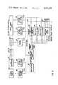
- FIG. 3is a block diagram of the preferred circuitry of our invention which illustrates how current flows within the device. A detailed circuit diagram appears in FIG. 4. In this circuit, we prefer to use the components listed in Table I which also contains the reference number given each component in the drawings.
- the keyboard 8is connected to latch 42 which in turn is connected to central processing unit 44, display decoder driver 46 and octal D type flip flops 48, 50 and 52.
- Flip flop 48is connected to the keyboard 8 and switches 12 and 14, which are used to select the alignment method to be used through hex inverters 49.
- a display decoder driver 46 and gates 47are connected to liquid crystal display 16.
- Flip flops 50 and 52are connected to LED's 18 thru 30. Terminals 39 can be provided for auxiliary indicators (not shown).
- a 16K programmable memory 54 and two 256 ⁇ 4 bit static RAM's 56 and 58form the memory unit 60.
- CPU 44inputs into memories 54, 56 and 58 providing the address for the memories and into decoder 62 and gates 64 which form the decoding unit 66. Both the decoding unit 66 and the memory unit 60 are connected to the display decoder driver 46. Decoder 66 connects to latch 42 through wire 70 and to flip flops 48, 50 and 52 through lines 72, 74, 76 and 78 (FIG. 3). Finally a schmitt trigger 45 is wired to the CPU 44 and acts as an oscillator. Terminals of the display 16, flip flop 48 and decoder 62 which are not used are marked "N.C.” in FIG. 4.
- s 29the amount to shim the front foot of the machine
- s 30the amount to shim the back foot of the machine.
Landscapes
- Engineering & Computer Science (AREA)
- Theoretical Computer Science (AREA)
- Computing Systems (AREA)
- Computer Hardware Design (AREA)
- Physics & Mathematics (AREA)
- General Engineering & Computer Science (AREA)
- General Physics & Mathematics (AREA)
- Management, Administration, Business Operations System, And Electronic Commerce (AREA)
- Length Measuring Devices With Unspecified Measuring Means (AREA)
Abstract
Description
TABLE I ______________________________________ Drawing Ref. Part No. Description ______________________________________ 8 KBA 3150Bowmar keyboard 16 FEO206C ANDliquid crystal display 47 CD4030BE RCA quad exclusive-orgate 46 ICM7211AMIPL Intersil four digit48, 50, 52 SN74LS273N Signetics 8- display decoder driver bit register 42 SN74LS373N Signetics 8-bit register 49 SN7406N Signetics hexinverter buffer driver 45 SN74LS13N Signetics dual 4input schmitt trigger 44 MK3880N Mostek Z80 -CPU 54 IP2716 Intel 16k (2k × 8) UVerasable PROM 62 SN74LS139N Signetics dual 1 - of 4decoder 64SN74LS32N Signetics quad 2 input or56, 58 IP5101L-1 gate Intel 256 × 4 bit static CMOS RAM ______________________________________
Claims (6)
Priority Applications (2)
| Application Number | Priority Date | Filing Date | Title |
|---|---|---|---|
| US06/329,707US4463438A (en) | 1981-12-11 | 1981-12-11 | Shaft alignment calculator |
| JP57185923AJPS5914780B2 (en) | 1981-12-11 | 1982-10-21 | Calculator for alignment |
Applications Claiming Priority (1)
| Application Number | Priority Date | Filing Date | Title |
|---|---|---|---|
| US06/329,707US4463438A (en) | 1981-12-11 | 1981-12-11 | Shaft alignment calculator |
Related Child Applications (1)
| Application Number | Title | Priority Date | Filing Date |
|---|---|---|---|
| US06/575,343Continuation-In-PartUS4623979A (en) | 1984-01-31 | 1984-01-31 | Method and calculator for determining offset and angularity of coupled shafts |
Publications (1)
| Publication Number | Publication Date |
|---|---|
| US4463438Atrue US4463438A (en) | 1984-07-31 |
Family
ID=23286638
Family Applications (1)
| Application Number | Title | Priority Date | Filing Date |
|---|---|---|---|
| US06/329,707Expired - LifetimeUS4463438A (en) | 1981-12-11 | 1981-12-11 | Shaft alignment calculator |
Country Status (2)
| Country | Link |
|---|---|
| US (1) | US4463438A (en) |
| JP (1) | JPS5914780B2 (en) |
Cited By (15)
| Publication number | Priority date | Publication date | Assignee | Title |
|---|---|---|---|---|
| DE3502877A1 (en)* | 1984-01-31 | 1985-08-08 | Industrial Maintenance Systems, Inc., Pittsburgh, Pa. | METHOD AND CALCULATOR FOR DETERMINING THE DISPLACEMENT AND ANGULARITY OF COUPLED SHAFTS |
| US4586264A (en)* | 1984-12-31 | 1986-05-06 | Industrial Maintenance Systems, Inc. | Methods for measuring alignment of coupled shafts |
| FR2644276A1 (en)* | 1989-03-08 | 1990-09-14 | Jose Casatejada | Method for visual indication of linear dimensional and/or angular criteria and the appliance for implementing it |
| WO1992006441A1 (en)* | 1990-10-05 | 1992-04-16 | Gateshead Manufacturing Corporation | Rotating machinery diagnostic system |
| US5263261A (en)* | 1992-06-03 | 1993-11-23 | Computational Systems, Incorporated | Shaft alignment data acquisition |
| US5272653A (en)* | 1992-10-13 | 1993-12-21 | Virgil Meta | Multilane keyboard for inch calculators |
| US5526282A (en)* | 1993-06-03 | 1996-06-11 | Computational Systems, Inc. | Alignment analyzer with graphical alignment tolerance display |
| US5621655A (en)* | 1993-06-03 | 1997-04-15 | Computational Systems, Inc. | Centralized alignment management system |
| US5684578A (en)* | 1994-06-23 | 1997-11-04 | Computational Systems, Inc. | Laser alignment head for use in shaft alignment |
| US5922977A (en)* | 1997-09-26 | 1999-07-13 | Pruftechnik Dieter Busch Ag | Method and apparatus for detecting a soft foot condition of at least one machine and for correction thereof |
| US6295544B1 (en)* | 1997-11-14 | 2001-09-25 | Western Wood Products Association | Calculator for determining sizes and spans of wooden structural supports |
| US6784986B2 (en) | 2001-05-17 | 2004-08-31 | Pruftechnik Dieter Busch Ag | Device and process for alignment of machine shafts |
| TWI422463B (en)* | 2011-08-24 | 2014-01-11 | China Steel Corp | Alignment method of rotary shaft |
| DE102015012077A1 (en) | 2015-09-22 | 2017-03-23 | Prüftechnik Dieter Busch Aktiengesellschaft | A method for aligning vertical axes of rotation of a rotatably mounted body and system for use in such a method |
| US11824339B2 (en) | 2021-08-28 | 2023-11-21 | Michael Arthur Rice | Work to old work electrical box clip |
Families Citing this family (4)
| Publication number | Priority date | Publication date | Assignee | Title |
|---|---|---|---|---|
| JPS632647U (en)* | 1986-06-24 | 1988-01-09 | ||
| JPS634758U (en)* | 1986-06-28 | 1988-01-13 | ||
| DE4018267A1 (en)* | 1989-06-07 | 1990-12-20 | T An T Kk | Electrical connector - has connecting pins encased to protect from damage |
| JPH0749740Y2 (en)* | 1993-06-14 | 1995-11-13 | 第一電装部品株式会社 | Combined locking device for connector frame |
Citations (8)
| Publication number | Priority date | Publication date | Assignee | Title |
|---|---|---|---|---|
| US3976975A (en)* | 1974-02-04 | 1976-08-24 | Texas Instruments Incorporated | Prompting calculator |
| US3979057A (en)* | 1974-10-29 | 1976-09-07 | Specialized Electronics Corporation | Electronic navigational computer |
| US3979058A (en)* | 1974-10-29 | 1976-09-07 | Specialized Electronics Corporation | Operator prompting system for stored program calculator |
| US4060719A (en)* | 1976-07-23 | 1977-11-29 | Dalinowski Alfred A | Computer for solving unknown parameters of geometrical figures |
| US4081859A (en)* | 1974-09-19 | 1978-03-28 | Goldsamt Alan B | Electronic calculator for feet-inch-fraction numerics |
| US4218755A (en)* | 1978-06-19 | 1980-08-19 | Root Steven A | Weather forecasting apparatus |
| US4234924A (en)* | 1978-09-11 | 1980-11-18 | Motorola, Inc. | Method of introducing a baseline measurement into electronic positioning apparatus |
| US4382280A (en)* | 1980-12-30 | 1983-05-03 | Mattel, Inc. | Electronic horse race analyzer |
- 1981
- 1981-12-11USUS06/329,707patent/US4463438A/ennot_activeExpired - Lifetime
- 1982
- 1982-10-21JPJP57185923Apatent/JPS5914780B2/ennot_activeExpired
Patent Citations (8)
| Publication number | Priority date | Publication date | Assignee | Title |
|---|---|---|---|---|
| US3976975A (en)* | 1974-02-04 | 1976-08-24 | Texas Instruments Incorporated | Prompting calculator |
| US4081859A (en)* | 1974-09-19 | 1978-03-28 | Goldsamt Alan B | Electronic calculator for feet-inch-fraction numerics |
| US3979057A (en)* | 1974-10-29 | 1976-09-07 | Specialized Electronics Corporation | Electronic navigational computer |
| US3979058A (en)* | 1974-10-29 | 1976-09-07 | Specialized Electronics Corporation | Operator prompting system for stored program calculator |
| US4060719A (en)* | 1976-07-23 | 1977-11-29 | Dalinowski Alfred A | Computer for solving unknown parameters of geometrical figures |
| US4218755A (en)* | 1978-06-19 | 1980-08-19 | Root Steven A | Weather forecasting apparatus |
| US4234924A (en)* | 1978-09-11 | 1980-11-18 | Motorola, Inc. | Method of introducing a baseline measurement into electronic positioning apparatus |
| US4382280A (en)* | 1980-12-30 | 1983-05-03 | Mattel, Inc. | Electronic horse race analyzer |
Non-Patent Citations (4)
| Title |
|---|
| Durkin, "Aligning Shafts Part II-Correcting Misalignment", Plant Engineering, Feb. 8, 1979, pp. 102-105. |
| Durkin, "Aligning Shafts Part I-Measuring Misalignment", Plant Engineering, Jan. 11, 1979, pp. 86-90. |
| Durkin, Aligning Shafts Part I Measuring Misalignment , Plant Engineering, Jan. 11, 1979, pp. 86 90.* |
| Durkin, Aligning Shafts Part II Correcting Misalignment , Plant Engineering, Feb. 8, 1979, pp. 102 105.* |
Cited By (19)
| Publication number | Priority date | Publication date | Assignee | Title |
|---|---|---|---|---|
| DE3502877A1 (en)* | 1984-01-31 | 1985-08-08 | Industrial Maintenance Systems, Inc., Pittsburgh, Pa. | METHOD AND CALCULATOR FOR DETERMINING THE DISPLACEMENT AND ANGULARITY OF COUPLED SHAFTS |
| US4623979A (en) | 1984-01-31 | 1986-11-18 | Industrial Maintenance Systems, Inc. | Method and calculator for determining offset and angularity of coupled shafts |
| US4586264A (en)* | 1984-12-31 | 1986-05-06 | Industrial Maintenance Systems, Inc. | Methods for measuring alignment of coupled shafts |
| FR2644276A1 (en)* | 1989-03-08 | 1990-09-14 | Jose Casatejada | Method for visual indication of linear dimensional and/or angular criteria and the appliance for implementing it |
| WO1992006441A1 (en)* | 1990-10-05 | 1992-04-16 | Gateshead Manufacturing Corporation | Rotating machinery diagnostic system |
| US5115406A (en)* | 1990-10-05 | 1992-05-19 | Gateshead Manufacturing Corporation | Rotating machinery diagnostic system |
| US5263261A (en)* | 1992-06-03 | 1993-11-23 | Computational Systems, Incorporated | Shaft alignment data acquisition |
| US5272653A (en)* | 1992-10-13 | 1993-12-21 | Virgil Meta | Multilane keyboard for inch calculators |
| US5526282A (en)* | 1993-06-03 | 1996-06-11 | Computational Systems, Inc. | Alignment analyzer with graphical alignment tolerance display |
| US5621655A (en)* | 1993-06-03 | 1997-04-15 | Computational Systems, Inc. | Centralized alignment management system |
| US5684578A (en)* | 1994-06-23 | 1997-11-04 | Computational Systems, Inc. | Laser alignment head for use in shaft alignment |
| US5922977A (en)* | 1997-09-26 | 1999-07-13 | Pruftechnik Dieter Busch Ag | Method and apparatus for detecting a soft foot condition of at least one machine and for correction thereof |
| EP0920953A3 (en)* | 1997-09-26 | 2002-02-13 | Prüftechnik Dieter Busch Ag | Method and apparatus for detecting or analyzing a Soft Foot condition of at least one machine |
| US6295544B1 (en)* | 1997-11-14 | 2001-09-25 | Western Wood Products Association | Calculator for determining sizes and spans of wooden structural supports |
| US6784986B2 (en) | 2001-05-17 | 2004-08-31 | Pruftechnik Dieter Busch Ag | Device and process for alignment of machine shafts |
| TWI422463B (en)* | 2011-08-24 | 2014-01-11 | China Steel Corp | Alignment method of rotary shaft |
| DE102015012077A1 (en) | 2015-09-22 | 2017-03-23 | Prüftechnik Dieter Busch Aktiengesellschaft | A method for aligning vertical axes of rotation of a rotatably mounted body and system for use in such a method |
| WO2017050753A1 (en) | 2015-09-22 | 2017-03-30 | Prüftechnik Dieter Busch AG | Method for aligning vertical axes of rotation of rotatably supported bodies and system for use in such a method |
| US11824339B2 (en) | 2021-08-28 | 2023-11-21 | Michael Arthur Rice | Work to old work electrical box clip |
Also Published As
| Publication number | Publication date |
|---|---|
| JPS58103062A (en) | 1983-06-18 |
| JPS5914780B2 (en) | 1984-04-06 |
Similar Documents
| Publication | Publication Date | Title |
|---|---|---|
| US4463438A (en) | Shaft alignment calculator | |
| US5115406A (en) | Rotating machinery diagnostic system | |
| US4586264A (en) | Methods for measuring alignment of coupled shafts | |
| US4462473A (en) | Apparatus for electronically determining postage in response to weight | |
| US3805036A (en) | Arrangement for a columnar display of variation gaging signals | |
| US4623979A (en) | Method and calculator for determining offset and angularity of coupled shafts | |
| US4315371A (en) | Preset brake device for line drawing machine, drafting machine or like | |
| US3545086A (en) | Surveying space coordinates in an engineering model | |
| US3789507A (en) | Machine element alignment system | |
| US3757418A (en) | Digital foot measuring instrument | |
| US3654438A (en) | Hexadecimal/decimal calculator | |
| US4154112A (en) | Front panel for a balancing machine | |
| FR2283488A1 (en) | BIPROGRAMMABLE ELECTRONIC ACCOUNTING MACHINE | |
| Brown | Visual and tactual judgments of surface roughness | |
| JPS5952701A (en) | Scale display device of measuring instrument | |
| CA1204931A (en) | Gage block management system | |
| US2210938A (en) | Apparatus for solving mathematical problems | |
| US6239804B1 (en) | Device and method for accurately obtaining measurement data for pool covers and other objects | |
| US4392651A (en) | Electronic logic game | |
| RU2019870C1 (en) | Device for checking written works of students | |
| CA2070657A1 (en) | Rotating machinery diagnostic system | |
| US2692432A (en) | Apparatus for drawing ellipses | |
| CN219798159U (en) | Digital pointer type height ruler | |
| US2563512A (en) | Slide rule for indicating productiv | |
| US2440438A (en) | Calculating device |
Legal Events
| Date | Code | Title | Description |
|---|---|---|---|
| AS | Assignment | Owner name:INDUSTRIAL MAINTENNANCE SYSTEMS, INC.; 1447 RIDGE Free format text:ASSIGNMENT OF ASSIGNORS INTEREST.;ASSIGNORS:ZATEZALO, JOHN M.;SPALLA, LUCIAN J.;REEL/FRAME:004003/0318 Effective date:19811203 Owner name:INDUSTRIAL MAINTENNANCE SYSTEMS, INC., PENNSYLVANI Free format text:ASSIGNMENT OF ASSIGNORS INTEREST;ASSIGNORS:ZATEZALO, JOHN M.;SPALLA, LUCIAN J.;REEL/FRAME:004003/0318 Effective date:19811203 | |
| CC | Certificate of correction | ||
| FEPP | Fee payment procedure | Free format text:PAYOR NUMBER ASSIGNED (ORIGINAL EVENT CODE: ASPN); ENTITY STATUS OF PATENT OWNER: SMALL ENTITY | |
| FPAY | Fee payment | Year of fee payment:4 | |
| FPAY | Fee payment | Year of fee payment:8 | |
| FEPP | Fee payment procedure | Free format text:PETITION RELATED TO MAINTENANCE FEES FILED (ORIGINAL EVENT CODE: PMFP); ENTITY STATUS OF PATENT OWNER: SMALL ENTITY | |
| REMI | Maintenance fee reminder mailed | ||
| REIN | Reinstatement after maintenance fee payment confirmed | ||
| FP | Lapsed due to failure to pay maintenance fee | Effective date:19960731 | |
| FPAY | Fee payment | Year of fee payment:12 | |
| SULP | Surcharge for late payment | ||
| FEPP | Fee payment procedure | Free format text:PETITION RELATED TO MAINTENANCE FEES GRANTED (ORIGINAL EVENT CODE: PMFG); ENTITY STATUS OF PATENT OWNER: SMALL ENTITY | |
| STCF | Information on status: patent grant | Free format text:PATENTED CASE | |
| PRDP | Patent reinstated due to the acceptance of a late maintenance fee | Effective date:19970131 |