US4460846A - Collector-output for hollow beam electron tubes - Google Patents
Collector-output for hollow beam electron tubesDownload PDFInfo
- Publication number
- US4460846A US4460846AUS06/510,465US51046583AUS4460846AUS 4460846 AUS4460846 AUS 4460846AUS 51046583 AUS51046583 AUS 51046583AUS 4460846 AUS4460846 AUS 4460846A
- Authority
- US
- United States
- Prior art keywords
- collector
- waveguide
- tube
- wave
- cavity
- Prior art date
- Legal status (The legal status is an assumption and is not a legal conclusion. Google has not performed a legal analysis and makes no representation as to the accuracy of the status listed.)
- Expired - Fee Related
Links
Images
Classifications
- H—ELECTRICITY
- H01—ELECTRIC ELEMENTS
- H01J—ELECTRIC DISCHARGE TUBES OR DISCHARGE LAMPS
- H01J23/00—Details of transit-time tubes of the types covered by group H01J25/00
- H01J23/02—Electrodes; Magnetic control means; Screens
- H01J23/027—Collectors
Definitions
- the inventionpertains to electron tubes for generating very high power at very high frequency.
- the gyrotronis a modern example.
- Such tubestypically use wave propagating circuits operating in a higher-order mode such as a mode with circular electric field.
- Gyrotron tubeshave generally been built with a beam-interaction cavity designed for supporting an electromagnetic wave in a TE oml mode.
- Accidental conversion of this mode to other modes which can also be supported in the cavityis a problem.
- Conversion to non-circular-field modesis caused by any departure of the circuits from circular symmetry.
- the hollow electron beamis expanded by terminating the axial magnetic focusing field.
- the beamis then collected on the surrounding waveguide wall, while the wave continues on through a dielectric output window.
- a principal disadvantage of the prior art arrangementis that the size, and thus the power-dissipating ability of the collector, is limited by the waveguide diameter.
- This power limitationmay be aided by increasing the diameter of the waveguide. If this is then subsequently reduced in diameter prior to the output window, for example, some of the higher order modes created at the taper discontinuities may be trapped and resonate. If sufficient loss is not provided in the expanded section, the amplitudes may build to such a level that the operation of the tube is disrupted through reflection to the cavity in modes capable of transmission to it. This results in erratic output and often frequency skipping to competing modes.
- An object of the inventionis to provide a gyrotron tube with increased power.
- a further objectis to provide a gyrotron tube with reduced spurious oscillations.
- FIG. 1is a schematic axial section of a prior art gyrotron oscillator.
- FIG. 2is a schematic axial section of the output section of a modified prior art gyrotron.
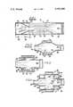
- FIG. 3is a schematic axial section of the output section of a gyrotron embodying the invention.
- FIG. 4is a schematic axial section of the collector section of a modified embodiment.
- FIG. 1is a sketch of a prior art gyrotron oscillator of the monotron type.
- the gyrotronis a microwave tube in which a beam of electrons having spiral motions in an axial magnetic field parallel to their drift direction interact with the transverse electric fields of a wave-supporting circuit.
- the eletric field in practical tubesis in a circular- electric-field mode.
- the wave- supporting circuitis a resonant cavity, usually resonating in a TE oml mode.
- a thermionic cathode 20is supported on the end plate 22 of the vacuum envelope. End plate 22 is sealed to the metallic accelerating anode 24 by a dielectric envelope member 26. Anode 24 in turn is sealed to the main tube body 28 by a second dielectric member 30.
- cathode 20is held at a potential negative to anode 24 by a power supply 32.
- Cathode 20is heated by a radiant internal heater (not shown). Thermionic electrons are drawn from its conical outer emitting surface by the attractive field of the coaxial conical anode 24. The entire structure is immersed in an axial magnetic field H produced by a surrounding solenoid magnet (not shown).
- the initial radial motion of the electronsis converted by the crossed electric and magnetic fields to a motion away from cathode 20 and spiralling about magnetic field lines, forming a hollow beam 34.
- Anode 24is held at a potential negative to tube body 28 by a second power supply 36, giving further axial acceleration to the beam 34.
- the strength of magnetic field His increased greatly, causing beam 34 to be compressed in diameter and also increasing its rotational energy at the expense of axial energy.
- the rotational energyis the part involved in the useful interaction with the circuit wave fields.
- the axial energymerely provides beam transport through the interacting region.
- Beam 34passes through a drift-tube or aperture 38 into the interaction cavity 40 which is resonant at the operating frequency in a TE oml mode.
- the magnetic field strength His adjusted so that the cylotron-frequency rotary motion of the electrons is approximately synchronous with the cavity resonance.
- the electronscan then deliver rotational energy to the circular electric field, setting up a sustained oscillation.
- the inner wall of body 28may be tapered in diameter to form an iris 42 of size selected to give the proper amount of energy coupling out of cavity 40.
- an outwardly tapered section 44couples the output energy into a uniform waveguide 46 which has a greater diameter than resonant cavity 40 in order to propagate a traveling wave.
- the magnetic field His reduced. Beam 34 thus expands in diameter under the influence of the expanding magnetic field lines and its own self-repulsive space charge. Beam 34 is then collected on the inner wall of waveguide 46, which also serves as a beam collector.
- a dielectric window 48as of alumina ceramic, is sealed across waveguide 46 to complete the vacuum envelope.
- the beam collector 46is also the output waveguide, its diameter is limited by the propagating dimensions for the operating TE om mode. Thus, its energy-dissipating capability is also limited. It is found that as TEom gyrotrons are scaled up in frequency the control of the electron beam in the collector becomes weak and therefore it becomes difficult using axisymmetric fields to spread the beam over an extended length of collector.
- FIG. 2is a sketch of the output portion of another prior art gyrotron.
- the cavity 40'is coupled thru a taper section 44' to a collector section 50 which has a diameter considerably larger than the remainder of the output waveguide 46'.
- a second taper 52slowly reduces the diameter from collector 50 to waveguide 46'.
- the wavepasses thru waveguide 46' thru a dielectric window 48' to the useful load.
- the scheme of FIG. 2reduces the dissipation power density because collector 50 is larger than the waveguide-sized collector of FIG. 1.
- the tapersthemselves can cause mode conversion, generally from one mode with circular symmetry to another with the same symmetry.
- the beam collector 50is also the output waveguide, its diameter is limited by the acceptable lengths of taper (up to it and down to the output guide) required to keep mode conversion to a small level.
- the section of enlarged waveguide formed by the collector 50can support higher order modes for which waveguide 46' and cavity 40' are cut off so that these modes cannot escape from the enlarged section.
- the Q of this sectionis thus very high and the spurious modes can build up to dangerously large amplitudes. These cause, through conversion to cavity-supported modes and reflection to the cavity, a disruption of the interaction, a loss of output and often frequency skipping to a competitive mode. For this reason, loss is normally provided in the expanded diameter collector to limit the amplitude of the trapped resonances. This may be in the form of a small gap of dimension such that the loss of the desired propagating modes is small, while spurious modes are propagated out and externally absorbed.
- FIG. 3is a section of the output end of a gyrotron tube embodying the invention.
- the resonant cavity 40"is connected by a tapered section 44" to waveguide 46" which is only slightly larger in diameter than cavity 40", but large enough to carry a traveling wave. This small taper is less prone to mode conversion than the large taper of prior art FIG. 2.
- Waveguide 46"continues thru window 48" to the useful load.
- Waveguide 46"is interrupted by a gap 56 in the region where beam 34" expands.
- the magnetic field patternis shaped so that beam 34" passes thru gap 56 without hitting waveguide 46".
- Beam 34"continues to expand and is collected on the inside surface 57 of the enlarged collector chamber 58.
- Collector surface 57is cooled by circulating water or other fluid 54".
- rings of wave-absorbing dielectric material 60such as a beryllia ceramic containing particles of silicon carbide, a very lossy material. Ring 60 may be brazed to the water-cooled wall of collector cavity 58 for conduction cooling, or it may be suspended so it can heat up and radiate the power it absorbs.
- some inner walls of collector 58may be coated with a high-resistance metallic coating. These lossy elements absorb any microwave radiation entering collector 58 thru waveguide gap 56, thus preventing the build-up of large amplitude resonances.
- the amount of wave energy leaking out of waveguide 46" into collector 58is a decreasing function of the diameter of waveguide 46" and an increasing function of the length of gap 56, both measured in free-space wavelengths. Both theoretical calculations and experimental measurements have demonstrated that the energy loss in a practical tube can be made tolerable. For example, measurements on a 5" diameter waveguide show that we could have a gap of 6.5" with a loss of less than 4% at 120 GH Z in the TE 02 mode of propagation, and we could have a 12" gap with less than 10% loss. These gaps could allow the electron beam to pass to a collector of sufficient diameter to allow proper dissipation.
- FIG. 4is a section of the output end of a gyrotron employing a somewhat different embodiment.
- the waves absorbing function in collector cavity 58'"is performed by sealing one or both ends with a wave-propagating dielectric window 62.
- Window 62is preferably of low-loss material such as high-alumina ceramic.
- Outside windows 62are water-load sections 64 containing lossy dielectric fluid 66, such as water, circulating thru inlet and outlet pipes 68.
- the unwanted wave energyis absorbed directly in the body of fluid 66, so the problem of convective heat transfer is greatly reduced.
- cavity 58"may be extended beyond windows 62 as air-filled waveguides terminated by any kind of conventional waveguide loads.
- the output waveguide 46'"may be tapered to a larger diameter 50'" similarly to the scheme of FIG. 3, the difference being that in FIG. 4 the surface 50'" does not have to dissipate the beam energy which is received on the even larger surface 57'" of collector cavity 58'".
Landscapes
- Microwave Tubes (AREA)
Abstract
Description
Claims (6)
Priority Applications (1)
| Application Number | Priority Date | Filing Date | Title |
|---|---|---|---|
| US06/510,465US4460846A (en) | 1981-04-06 | 1983-07-01 | Collector-output for hollow beam electron tubes |
Applications Claiming Priority (2)
| Application Number | Priority Date | Filing Date | Title |
|---|---|---|---|
| US25161281A | 1981-04-06 | 1981-04-06 | |
| US06/510,465US4460846A (en) | 1981-04-06 | 1983-07-01 | Collector-output for hollow beam electron tubes |
Related Parent Applications (1)
| Application Number | Title | Priority Date | Filing Date |
|---|---|---|---|
| US25161281AContinuation | 1981-04-06 | 1981-04-06 |
Publications (1)
| Publication Number | Publication Date |
|---|---|
| US4460846Atrue US4460846A (en) | 1984-07-17 |
Family
ID=26941716
Family Applications (1)
| Application Number | Title | Priority Date | Filing Date |
|---|---|---|---|
| US06/510,465Expired - Fee RelatedUS4460846A (en) | 1981-04-06 | 1983-07-01 | Collector-output for hollow beam electron tubes |
Country Status (1)
| Country | Link |
|---|---|
| US (1) | US4460846A (en) |
Cited By (8)
| Publication number | Priority date | Publication date | Assignee | Title |
|---|---|---|---|---|
| US4523127A (en)* | 1983-02-02 | 1985-06-11 | Ga Technologies Inc. | Cyclotron resonance maser amplifier and waveguide window |
| US4584980A (en)* | 1982-10-08 | 1986-04-29 | Daimler-Benz Aktiengesellschaft | Electrically operated valve |
| US5015914A (en)* | 1988-12-09 | 1991-05-14 | Varian Associates, Inc. | Couplers for extracting RF power from a gyrotron cavity directly into fundamental mode waveguide |
| US5061912A (en)* | 1990-07-25 | 1991-10-29 | General Atomics | Waveguide coupler having opposed smooth and opposed corrugated walls for coupling HE1,1 mode |
| WO1992013357A1 (en)* | 1991-01-25 | 1992-08-06 | Varian Associates, Inc. | Gyrotron with radial beam extraction |
| US8489015B2 (en)* | 2005-09-19 | 2013-07-16 | Wireless Expressways Inc. | Waveguide-based wireless distribution system and method of operation |
| CN104091987A (en)* | 2014-07-01 | 2014-10-08 | 中国科学院等离子体物理研究所 | A Megawatt Corrugated Waveguide Attenuator |
| CN109830417A (en)* | 2019-01-21 | 2019-05-31 | 电子科技大学 | A kind of multistage interaction cavity being continuously adjusted gyrotron for frequency |
Citations (1)
| Publication number | Priority date | Publication date | Assignee | Title |
|---|---|---|---|---|
| US2486398A (en)* | 1943-05-29 | 1949-11-01 | Sperry Corp | Velocity modulation device and method |
- 1983
- 1983-07-01USUS06/510,465patent/US4460846A/ennot_activeExpired - Fee Related
Patent Citations (1)
| Publication number | Priority date | Publication date | Assignee | Title |
|---|---|---|---|---|
| US2486398A (en)* | 1943-05-29 | 1949-11-01 | Sperry Corp | Velocity modulation device and method |
Cited By (11)
| Publication number | Priority date | Publication date | Assignee | Title |
|---|---|---|---|---|
| US4584980A (en)* | 1982-10-08 | 1986-04-29 | Daimler-Benz Aktiengesellschaft | Electrically operated valve |
| US4523127A (en)* | 1983-02-02 | 1985-06-11 | Ga Technologies Inc. | Cyclotron resonance maser amplifier and waveguide window |
| US5015914A (en)* | 1988-12-09 | 1991-05-14 | Varian Associates, Inc. | Couplers for extracting RF power from a gyrotron cavity directly into fundamental mode waveguide |
| US5061912A (en)* | 1990-07-25 | 1991-10-29 | General Atomics | Waveguide coupler having opposed smooth and opposed corrugated walls for coupling HE1,1 mode |
| WO1992013357A1 (en)* | 1991-01-25 | 1992-08-06 | Varian Associates, Inc. | Gyrotron with radial beam extraction |
| US5180944A (en)* | 1991-01-25 | 1993-01-19 | Varian Associates, Inc. | Gyrotron with a mode convertor which reduces em wave leakage |
| US8489015B2 (en)* | 2005-09-19 | 2013-07-16 | Wireless Expressways Inc. | Waveguide-based wireless distribution system and method of operation |
| US8897695B2 (en) | 2005-09-19 | 2014-11-25 | Wireless Expressways Inc. | Waveguide-based wireless distribution system and method of operation |
| CN104091987A (en)* | 2014-07-01 | 2014-10-08 | 中国科学院等离子体物理研究所 | A Megawatt Corrugated Waveguide Attenuator |
| CN104091987B (en)* | 2014-07-01 | 2016-07-06 | 中国科学院等离子体物理研究所 | A kind of MW class corrugated waveguide attenuator |
| CN109830417A (en)* | 2019-01-21 | 2019-05-31 | 电子科技大学 | A kind of multistage interaction cavity being continuously adjusted gyrotron for frequency |
Similar Documents
| Publication | Publication Date | Title |
|---|---|---|
| CA1178710A (en) | Mode suppression means for gyrotron cavities | |
| US4851788A (en) | Mode suppressors for whispering gallery gyrotron | |
| US3432721A (en) | Beam plasma high frequency wave generating system | |
| US4460846A (en) | Collector-output for hollow beam electron tubes | |
| US4523127A (en) | Cyclotron resonance maser amplifier and waveguide window | |
| CA1175144A (en) | Collector-output for hollow beam electron tubes | |
| CA1170365A (en) | Gyrotron with improved stability | |
| US4531103A (en) | Multidiameter cavity for reduced mode competition in gyrotron oscillator | |
| JP2951420B2 (en) | Multi-beam microwave tube with coaxial output | |
| US4926093A (en) | Gyrotron device | |
| Kreischer et al. | High-power operation of a 170 GHz megawatt gyrotron | |
| US5521551A (en) | Method for suppressing second and higher harmonic power generation in klystrons | |
| US3379926A (en) | Coaxial magnetron having slot mode suppressing lossy material in anode resonators | |
| US5180944A (en) | Gyrotron with a mode convertor which reduces em wave leakage | |
| JP3133379B2 (en) | Gyrotron oscillation tube | |
| US3551729A (en) | Traveling wave tube helix support structure | |
| EP0411890A1 (en) | Gyrotron | |
| JPS627655B2 (en) | ||
| GB2152742A (en) | Microwave amplifiers and oscillators | |
| US3324337A (en) | High frequency electron discharge device and focusing means therefor | |
| US3260886A (en) | Velocity modulation device having a coaxial output | |
| SU496870A1 (en) | Gyrokon | |
| JPH03192633A (en) | gyrotron oscillator tube | |
| GB2152740A (en) | Microwave amplifiers and oscillators | |
| JPH06152207A (en) | Microwave power absorber |
Legal Events
| Date | Code | Title | Description |
|---|---|---|---|
| FEPP | Fee payment procedure | Free format text:PAYOR NUMBER ASSIGNED (ORIGINAL EVENT CODE: ASPN); ENTITY STATUS OF PATENT OWNER: LARGE ENTITY | |
| FPAY | Fee payment | Year of fee payment:4 | |
| FPAY | Fee payment | Year of fee payment:8 | |
| FEPP | Fee payment procedure | Free format text:PAYER NUMBER DE-ASSIGNED (ORIGINAL EVENT CODE: RMPN); ENTITY STATUS OF PATENT OWNER: LARGE ENTITY Free format text:PAYOR NUMBER ASSIGNED (ORIGINAL EVENT CODE: ASPN); ENTITY STATUS OF PATENT OWNER: LARGE ENTITY | |
| AS | Assignment | Owner name:COMMUNICATIONS & POWER INDUSTRIES, INC., CALIFORNI Free format text:ASSIGNMENT OF ASSIGNORS INTEREST;ASSIGNOR:VARIAN ASSOCIATES, INC.;REEL/FRAME:007603/0223 Effective date:19950808 | |
| REMI | Maintenance fee reminder mailed | ||
| LAPS | Lapse for failure to pay maintenance fees | ||
| FP | Lapsed due to failure to pay maintenance fee | Effective date:19960717 | |
| AS | Assignment | Owner name:FOOTHILL CAPITAL CORPORATION, CALIFORNIA Free format text:SECURITY INTEREST;ASSIGNOR:COMMUNICATION & POWER INDUSTRIES, INC.;REEL/FRAME:011590/0575 Effective date:20001215 | |
| AS | Assignment | Owner name:COMMUNICATIONS & POWER INDUSTRIES, INC., CALIFORNI Free format text:RELEASE BY SECURED PARTY;ASSIGNOR:WELLS FARGO FOOTHILL, INC. (FKA FOOTHILL CAPITAL CORPORATION);REEL/FRAME:014301/0248 Effective date:20040123 | |
| AS | Assignment | Owner name:UBS AG, STAMFORD BRANCH, AS COLLATERAL AGENT, CONN Free format text:SECURITY INTEREST;ASSIGNOR:COMMUNICATIONS & POWER INDUSTRIES, INC.;REEL/FRAME:014981/0981 Effective date:20040123 | |
| AS | Assignment | Owner name:CPI ECONCO DIVISION (FKA ECONCO BROADCAST SERVICE, Free format text:RELEASE;ASSIGNOR:UBS AG, STAMFORD BRANCH, AS COLLATERAL AGENT;REEL/FRAME:025810/0162 Effective date:20110211 Owner name:CPI MALIBU DIVISION (FKA MALIBU RESEARCH ASSOCIATE Free format text:RELEASE;ASSIGNOR:UBS AG, STAMFORD BRANCH, AS COLLATERAL AGENT;REEL/FRAME:025810/0162 Effective date:20110211 Owner name:CPI SUBSIDIARY HOLDINGS INC. (NOW KNOW AS CPI SUBS Free format text:RELEASE;ASSIGNOR:UBS AG, STAMFORD BRANCH, AS COLLATERAL AGENT;REEL/FRAME:025810/0162 Effective date:20110211 Owner name:COMMUNICATIONS & POWER INDUSTRIES INTERNATIONAL IN Free format text:RELEASE;ASSIGNOR:UBS AG, STAMFORD BRANCH, AS COLLATERAL AGENT;REEL/FRAME:025810/0162 Effective date:20110211 Owner name:CPI INTERNATIONAL INC., CALIFORNIA Free format text:RELEASE;ASSIGNOR:UBS AG, STAMFORD BRANCH, AS COLLATERAL AGENT;REEL/FRAME:025810/0162 Effective date:20110211 Owner name:COMMUNICATIONS & POWER INDUSTRIES LLC, CALIFORNIA Free format text:RELEASE;ASSIGNOR:UBS AG, STAMFORD BRANCH, AS COLLATERAL AGENT;REEL/FRAME:025810/0162 Effective date:20110211 Owner name:COMMUNICATIONS & POWER INDUSTRIES ASIA INC., CALIF Free format text:RELEASE;ASSIGNOR:UBS AG, STAMFORD BRANCH, AS COLLATERAL AGENT;REEL/FRAME:025810/0162 Effective date:20110211 | |
| STCH | Information on status: patent discontinuation | Free format text:PATENT EXPIRED DUE TO NONPAYMENT OF MAINTENANCE FEES UNDER 37 CFR 1.362 |