US4459996A - Ear pathology diagnosis apparatus and method - Google Patents
Ear pathology diagnosis apparatus and methodDownload PDFInfo
- Publication number
- US4459996A US4459996AUS06/358,831US35883182AUS4459996AUS 4459996 AUS4459996 AUS 4459996AUS 35883182 AUS35883182 AUS 35883182AUS 4459996 AUS4459996 AUS 4459996A
- Authority
- US
- United States
- Prior art keywords
- ear
- signal
- khz
- generating
- microphone
- Prior art date
- Legal status (The legal status is an assumption and is not a legal conclusion. Google has not performed a legal analysis and makes no representation as to the accuracy of the status listed.)
- Expired - Lifetime
Links
- 238000000034methodMethods0.000titleclaimsabstractdescription23
- 238000003745diagnosisMethods0.000titleclaimsabstractdescription8
- 230000007170pathologyEffects0.000titleabstractdescription4
- 210000000613ear canalAnatomy0.000claimsabstractdescription24
- 230000001902propagating effectEffects0.000claimsabstractdescription3
- 239000000523sampleSubstances0.000claimsdescription29
- 238000012360testing methodMethods0.000claimsdescription29
- 210000003128headAnatomy0.000claimsdescription20
- 230000001575pathological effectEffects0.000claimsdescription10
- 238000012545processingMethods0.000claimsdescription9
- 238000004891communicationMethods0.000claimsdescription4
- 210000000959ear middleAnatomy0.000abstractdescription14
- 210000003454tympanic membraneAnatomy0.000abstractdescription5
- 206010063045EffusionDiseases0.000abstractdescription3
- 206010033078Otitis mediaDiseases0.000abstractdescription3
- 238000005259measurementMethods0.000description6
- 238000010586diagramMethods0.000description5
- 238000001802infusionMethods0.000description3
- 101100453960Drosophila melanogaster klar geneProteins0.000description2
- 238000013459approachMethods0.000description2
- 230000005540biological transmissionEffects0.000description2
- 238000002847impedance measurementMethods0.000description2
- 230000005236sound signalEffects0.000description2
- 206010062545Middle ear effusionDiseases0.000description1
- 238000012631diagnostic techniqueMethods0.000description1
- 210000005069earsAnatomy0.000description1
- 230000007274generation of a signal involved in cell-cell signalingEffects0.000description1
- 239000003365glass fiberSubstances0.000description1
- 238000003780insertionMethods0.000description1
- 230000037431insertionEffects0.000description1
- 239000007788liquidSubstances0.000description1
- 208000022949middle ear diseaseDiseases0.000description1
- 208000005923otitis media with effusionDiseases0.000description1
- 125000006850spacer groupChemical group0.000description1
- 210000001050stapeAnatomy0.000description1
- 230000003068static effectEffects0.000description1
Images


Classifications
- A—HUMAN NECESSITIES
- A61—MEDICAL OR VETERINARY SCIENCE; HYGIENE
- A61B—DIAGNOSIS; SURGERY; IDENTIFICATION
- A61B5/00—Measuring for diagnostic purposes; Identification of persons
- A61B5/68—Arrangements of detecting, measuring or recording means, e.g. sensors, in relation to patient
- A61B5/6801—Arrangements of detecting, measuring or recording means, e.g. sensors, in relation to patient specially adapted to be attached to or worn on the body surface
- A61B5/6813—Specially adapted to be attached to a specific body part
- A61B5/6814—Head
- A61B5/6815—Ear
- A61B5/6817—Ear canal
- A—HUMAN NECESSITIES
- A61—MEDICAL OR VETERINARY SCIENCE; HYGIENE
- A61B—DIAGNOSIS; SURGERY; IDENTIFICATION
- A61B5/00—Measuring for diagnostic purposes; Identification of persons
- A61B5/12—Audiometering
Definitions
- the present inventionrelates generally to devices and methods for diagnosis of pathological ear conditions, and particularly to those devices and methods in which there are determined quantities related to the complex acoustic impedance of components of the ear.
- a probesuch as that described in U.S. Pat. No. 4,057,051 (Kerovac) is inserted into the ear canal in such a way that the ear is effectively sealed from the external atmosphere.
- the probeis usually supplied with a means for varying the pressure within the ear canal above and below ambient pressure.
- a continuous wave (CW) sound signalis introduced into the ear canal.
- the signal from the sound source, and the signal from the probe-mounted transducer,are variously combined to yield a measure of simple compliance (Klar, and Ward), impedance (Zwislocki, Bennett), or complex admittance (Arguimbau), at the entrance to the ear canal.
- the present inventionprovides a method and apparatus for diagnosis of various ear pathologies, including the diagnosis of effusions of the middle ear associated with Otitis Media.
- the methodis practiced by determining a quantity related to the complex acoustic impedance of the middle ear, namely the Vector Sum (VS) of an incident signal, propagating down the ear canal (treated as a lossy transmission line), and the same signal reflected from the tympanic membrance (ear drum) and middle ear components.
- VSVector Sum
- results of such determination madeare examined to determine whether there is present a pathological dip in this vector sum, of a characteristic shape, and in a characteristic frequency region having a center lying between approximately 1.5 KHz and 5.5 KHz, depending on the age of the patient and on the ear pathology involved.
- the methodmay be practiced with the apparatus of the present invention, which, in a preferred embodiment, includes a test head having a sound cavity, a transducer placed so as to create a sound field in the cavity, a hollow probe for conveying sound from the cavity to the vicinity of the ear canal, and for impedance matching to the ear canal, and a microphone suitably placed at the junction of the cavity and the probe.
- the apparatusalso has a signal generator connected to the transducer, and appropriate arrangements for processing the signal from the microphone.
- the apparatusprovides a pulsed or continuous wave signal that, over a suitable interval of time, varies in frequency and amplitude.
- the methodmay be practiced with the ear at atmospheric pressure, and at least partially open to air in the atmosphere, thus making the invention particularly useful in the diagnosis of middle ear disease in young children and infants where insertion of probes is often not feasible.
- FIG. 1shows a perspective view of a test head in accordance with the present invention
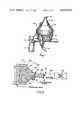
- FIG. 2shows a cross-section of the test head illustrated in FIG. 1;
- FIG. 3presents a block diagram of an analog apparatus in accordance with the invention which utilizes a continuous sweep system
- FIG. 4presents a graph of measurements of the vector sum in a typical normal ear and the same quantity in an ear having middle ear effusion;
- FIG. 5presents a block diagram of an apparatus in accordance with the present invention utilizing a tram of short audio pulses a discrete incremented in successive frequency steps through the drain system;
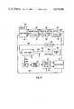
- FIG. 6shows a block diagram of a digitalized version of an embodiment of the invention utilizing a discrete sweep system.
- FIG. 1is a perspective view of a test head 34 in accordance with a preferred embodiment of the present invention.
- the microphone preamplifier 38is shown mounted on the rear of the transducer assembly 13.
- a microphone(shown in later figure) is mounted inside the hollow probe assembly 12. The diameter of the probe is adjusted by changing the probe extension 11.
- the probe assembly 12includes funnel-shaped section 14 in communication with sound cavity housing 14.
- the toggle switch 15 on handle 17controls a recorder for capturing the output of the instrument.
- One of the cables 16is shielded and carries signals from the probe-mounted preamplifier, while the other cable carries recorder control signals.
- FIG. 2shows in cross section a view of the test head in FIG. 1.
- the test headincludes a transducer 21 that creates a sound field in sound cavity 23. Sound in the cavity 23 is channeled through probe 25 to the vicinity of the ear canal 290.
- the probehas a funnel-shaped section 251 and two-piece linear section 252. Section 252 is choosen to match dimensions of the ear canal under test. For children's ears, I have found that generally excellent results are obtained with length A of the linear portion 252 of the probe equal to approximately 1 cm and inner diameter B of the same section in the rage of approximately 0.25 to 0.75 cm. Similarly, good results are obtained when length C along the side of portion 251 of the probe is about 5 cm and the approximate outer diameter D of the large end of the probe which is in contact with the sound cavity wall, is approximately 7 cm.
- the operating principles of the inventionare such that the probe extension need not be inserted into the ear canal.
- the incident sound wave created by transducer 21 in the test heademanates from the test head at the tip 27 of the probe 25 and enters the ear canal 290. Thereafter, a portion of the incident wave is reflected by structures of the ear, including the tympanic membrane, stapes, and other components of the middle ear.
- the amplitude and phase of the reflected sound waveare a function of the test frequency used and the complex acoustic impedance of the ear canal and middle ear. In a healthy ear, one expects some minimal reflection from the tympanic membrane and middle ear.
- the complex acoustic impedance of the middle eardepends very strongly on the conditions within the middle ear, and in particular on whether there is an infusion (liquid) present within the middle ear.
- the microphone 24is located within the test probe 25 at the junction of the straight section 252 and the conical section 251. As a result, the microphone 24 measures the net sound pressure at this point; this net sound pressure is the vector sum of the incident and reflected signals.
- the sound cavity 23is filled with loosely packed glass fibers 26. Good results have been obtained when the transducer 21 is one side of an electrostatic head phone, such as Koss ESP/10.
- the microphoneis a condenser microphone.
- FIG. 3illustrates in a block diagram an embodiment of the apparatus of the invention utilizing all analog techniques with a continuous sweep system.
- a sweep generator 31provides a sweeped frequency output over line 312. Typically, the sweep may be from 1 kHz through about 15 kHz. A typical period for a full sweep may range from 20 milliseconds to about 10 seconds. These are, however, only typical figures. All that is necessary is that there be a frequency output that covers one or more of the resonant points of the ear canal "transmission line" as “terminated" by the middle ear. These points occur regularly at multiples of one quarter wavelength. The following resonant points have been found to be particularly useful for diagnostic purposes: 1/4 wave, 1/2 wave, 3/4 wave, and one wavelength. In a normal adult ear these wavelengths correspond to frequencies of approximately 3.5, 7, 10.5, and 14 KHz.
- the sweep signalitself appears as an output over line 311 for use in synchronizing the display device 38.
- the sound pressure from the transduceris kept at a constant level by feedback over line 322 to the attenuator 32.
- the voltage-controlled attenuator in this embodimentis continuously adjustable to a maximum of 20 db.
- the output from the microphone 24 shown in FIG. 2is sent over line 341 from the test head 34 through a preamplifier 35 to a bandpass filter 36.
- the bandpass filtertypically passes signals from approximately 500 kHz to 20 kHz.
- the output of the bandpass filter 36goes into both an RMS-to-DC converter 371 and a phase detector 372, so as to provide information as to both amplitude and phase of the signal in the microphone, which, as discussed in connection with FIG. 2, is the vector sum of the incident and reflected signals.
- the outputs of these devices 371 and 372are then fed to an appropriate display device 38. Where the device is an oscilloscope, a high sweep rate, typically 50 Hz, can provide a flicker-free display. When the display device is a chart recorder, the sweep rate is typically 1 second or longer.
- FIG. 4shows a typical graph produced when the embodiment shown in FIG. 3 is used in testing for middle ear infusions and Otitis Media.
- Curve 41is a typical response curve for a nearly normal ear of a five-year-old child
- curve 42is typical curve for this same child with a pronounced middle ear infusion. I have discovered that the presence of effusion causes a pronounced dip in the magnitude of the vector sum at a frequency associated with quarter wave reasonance about 3.5 kHz in an adult. I have confirmed the theoretical validity of the dip as a diagnostic tool by computer analysis and modeling.
- FIG. 5shows another embodiment of the apparatus of the present invention.
- a train of pulsed signalsis used, each pulse at a different frequency.
- Components bearing numbers corresponding to those numbers discussed in connection with FIG. 3function in a manner analogously to their correspondingly numbered components in FIG. 3.
- the signal to the test head 34originates with the pulse-sweep generator 51.
- the generatorprovides a series of pulses, each of which has a width of approximately 10 milliseconds, with a pulse repetition rate of approximately 100 Hz.
- Eachhas a different center frequency, the first pulse having a frequency of approximately 1 kHz.
- each succeeding pulsehas a frequency approximately 120 Hz higher than its predecessor pulse, until the final pulse in a given train of pulses has a frequency of approximately 15 kHz.
- a complete diagnostic measurementcan be made with 0.5 second long burst of 50 pulses.
- FIG. 6A digital version of the apparatus, also employing discrete frequency jumps in a CW signal, is illustrated in block diagram in FIG. 6.
- the processing of the signal from the microphone output of the line 341is similar to the processing shown in connection with FIGS. 3 and 5.
- the principal differenceis the method of generating the signal going to the transducer in the test head 34.
- the signalsare generated in a microprocessor-based computer 611.
- the computer's input and outputare over lines 632 and 621 respectively from analog-to-digital converter 63 and digital-to-analog converter 62, respectively.
- the converters 62 and 63are each preceded (in the case of converter 63) or followed (in the case of converter 62) by a anti-aliasing bandpass filter 65-64 and buffer amplifiers 67-66.
- Buffer amplifer 67receives over line 671 the output from the multiplexer 69, which in turn receives the information from the RMS-to-DC converter 371 and phase detector 372, which were discussed in connection with FIG. 3.
- the processed microphone outputpasses through multiplexer 69, buffer amplifier 67, anti-aliasing bandpass filter 65, and analog-to-digital converter 63, to the microprocessor 611 so that additional signal processing can be performed to enhance the diagnostic value of the basic vector sum signal.
- the microprocessorgenerates the swept signals that go to the transducer over line 681 via power applifier 68.
- the signal waveformsare stored in tables in computer memory containing time-sampled waveforms, so that the signals are generated digitally for every frequency sweep. Entries in the tables are scanned at user-defined rates, to produce the stepped frequency sweeps. In this fashion, there can be controlled many different parameters, such as starting frequency, stopping frequency, frequency step size, frequency linearity, etc.
- This same techniqueprovides precise control over the amplitude of the signal at each frequency step, so as to compensate for signal channel gain variations between the output of digital-to-analog converter 62 and the transducer in the test probe discussed with reference to FIG. 2. Further, with respect to signal generation, use of the approach shown in FIG.
- signal typee.g., pulse or CW
- signal amplitudee.g., CW
- signal phasee.g., whether the signal includes a burst of pulses as the device in connection with FIG. 6 or a continuous analog generated sweep, as in FIG. 3.
- processing of the collected datacan also be achieved readily. Quantitative results can be displayed, or the computer can be asked to detect the presence, frequency center line, shape and depth of the characteristic dip described previously, and give a single "go" - "no go” response to the user.
Landscapes
- Health & Medical Sciences (AREA)
- Life Sciences & Earth Sciences (AREA)
- Engineering & Computer Science (AREA)
- Physics & Mathematics (AREA)
- Molecular Biology (AREA)
- General Health & Medical Sciences (AREA)
- Biophysics (AREA)
- Biomedical Technology (AREA)
- Heart & Thoracic Surgery (AREA)
- Medical Informatics (AREA)
- Otolaryngology (AREA)
- Surgery (AREA)
- Animal Behavior & Ethology (AREA)
- Pathology (AREA)
- Public Health (AREA)
- Veterinary Medicine (AREA)
- Acoustics & Sound (AREA)
- Audiology, Speech & Language Pathology (AREA)
- Multimedia (AREA)
- Measuring Pulse, Heart Rate, Blood Pressure Or Blood Flow (AREA)
- Measurement Of The Respiration, Hearing Ability, Form, And Blood Characteristics Of Living Organisms (AREA)
Abstract
Description
______________________________________ Measure- Ear Canal ment Frequency Seal U.S. Pat. No. Inventor Technique in Hertz Required? ______________________________________ 3,294,193 Zwislocki Impedance 220 Yes Bridge 3,757,769 Arguimbau Measure 220 & Yes Complex Y 660 4,002,161 Klar Measure 220 Yes Compliance 4,009,707 Ward Measure 220 Yes Compliance 4,079,198 Bennett Impedance Variable Yes Bridge ______________________________________
Claims (15)
Priority Applications (7)
| Application Number | Priority Date | Filing Date | Title |
|---|---|---|---|
| US06/358,831US4459996A (en) | 1982-03-16 | 1982-03-16 | Ear pathology diagnosis apparatus and method |
| EP83901478AEP0103640B1 (en) | 1982-03-16 | 1983-03-16 | Ear pathology diagnosis apparatus and method |
| US06/557,123US4601295A (en) | 1982-03-16 | 1983-03-16 | Ear pathology diagnosis apparatus and method |
| PCT/US1983/000380WO1983003192A1 (en) | 1982-03-16 | 1983-03-16 | Ear pathology diagnosis apparatus and method |
| DE8383901478TDE3382619T2 (en) | 1982-03-16 | 1983-03-16 | DEVICE AND METHOD FOR DIAGNOSIS OF EAR PATHOLOGY. |
| AU15114/83AAU1511483A (en) | 1982-03-16 | 1983-03-16 | Ear pathology diagnosis apparatus and method |
| DK524483ADK524483A (en) | 1982-03-16 | 1983-11-16 | PROCEDURE AND APPARATUS FOR DIAGNOSTICING DISEASES |
Applications Claiming Priority (1)
| Application Number | Priority Date | Filing Date | Title |
|---|---|---|---|
| US06/358,831US4459996A (en) | 1982-03-16 | 1982-03-16 | Ear pathology diagnosis apparatus and method |
Related Child Applications (1)
| Application Number | Title | Priority Date | Filing Date |
|---|---|---|---|
| US06/557,123Continuation-In-PartUS4601295A (en) | 1982-03-16 | 1983-03-16 | Ear pathology diagnosis apparatus and method |
Publications (1)
| Publication Number | Publication Date |
|---|---|
| US4459996Atrue US4459996A (en) | 1984-07-17 |
Family
ID=23411222
Family Applications (1)
| Application Number | Title | Priority Date | Filing Date |
|---|---|---|---|
| US06/358,831Expired - LifetimeUS4459996A (en) | 1982-03-16 | 1982-03-16 | Ear pathology diagnosis apparatus and method |
Country Status (4)
| Country | Link |
|---|---|
| US (1) | US4459996A (en) |
| EP (1) | EP0103640B1 (en) |
| DK (1) | DK524483A (en) |
| WO (1) | WO1983003192A1 (en) |
Cited By (16)
| Publication number | Priority date | Publication date | Assignee | Title |
|---|---|---|---|---|
| US4586194A (en)* | 1983-03-09 | 1986-04-29 | Hitachi, Ltd. | Earphone characteristic measuring device |
| US4596252A (en)* | 1985-05-06 | 1986-06-24 | Medtronic, Inc. | Pacer sense amplifier |
| US4601295A (en)* | 1982-03-16 | 1986-07-22 | Teele John H | Ear pathology diagnosis apparatus and method |
| US4674123A (en)* | 1983-05-27 | 1987-06-16 | Frederic Michas | Test bench for the adjustment of electro-acoustic channels and particularly of devices for auditory correction |
| US4754748A (en)* | 1984-08-31 | 1988-07-05 | Jerry Antowski | Apparatus for generating pneumatic pressure pulses for application to the external acoustic meatus of a patient |
| WO1989001315A1 (en)* | 1987-08-12 | 1989-02-23 | Phoenix Project Of Madison, Inc. | Method and apparatus for real ear measurements |
| US4813430A (en)* | 1987-08-14 | 1989-03-21 | Nicolet Instrument Corporation | Microphonic probe tube mounting for real ear measurements |
| US4841986A (en)* | 1986-09-19 | 1989-06-27 | Marchbanks Robert J | Method and apparatus for measuring intracranial fluid pressure |
| WO1993020746A1 (en)* | 1992-04-08 | 1993-10-28 | Sensimetrics Corporation | System and method for testing adequacy of human hearing |
| US5526819A (en)* | 1990-01-25 | 1996-06-18 | Baylor College Of Medicine | Method and apparatus for distortion product emission testing of heating |
| US5594174A (en)* | 1994-06-06 | 1997-01-14 | University Of Washington | System and method for measuring acoustic reflectance |
| US5792072A (en)* | 1994-06-06 | 1998-08-11 | University Of Washington | System and method for measuring acoustic reflectance |
| WO1999037210A1 (en) | 1998-01-23 | 1999-07-29 | Mdi Instruments, Inc. | A device and process for measuring acoustic reflectance |
| US6048320A (en)* | 1996-11-25 | 2000-04-11 | Brainard, Ii; Edward C. | Inner ear diagnostic apparatus |
| US20040171966A1 (en)* | 1997-04-03 | 2004-09-02 | Iseberg Steven J. | Hand-held hearing screener apparatus |
| US8241224B2 (en) | 2005-03-16 | 2012-08-14 | Sonicom, Inc. | Test battery system and method for assessment of auditory function |
Families Citing this family (3)
| Publication number | Priority date | Publication date | Assignee | Title |
|---|---|---|---|---|
| GB8713116D0 (en)* | 1987-06-04 | 1987-07-08 | Kemp D T | Hearing faculty testing |
| DK174851B1 (en)* | 1993-12-10 | 2003-12-22 | Madsen Electronics As | Oto-acoustic emission analyzer |
| US20210186426A1 (en) | 2018-09-07 | 2021-06-24 | University Of Washington | System and method for detection of middle ear fluids |
Citations (11)
| Publication number | Priority date | Publication date | Assignee | Title |
|---|---|---|---|---|
| DE147313C (en)* | ||||
| US3294193A (en)* | 1966-12-27 | Acoustic impedance measuring instrument | ||
| US3395697A (en)* | 1965-12-08 | 1968-08-06 | Navy Usa | Acoustic reflexometer |
| US3757769A (en)* | 1971-11-01 | 1973-09-11 | Grason Stadler Comp Inc | Acoustic admittance testing apparatus |
| US3882848A (en)* | 1974-01-24 | 1975-05-13 | American Electromedics Corp | Test probe for an impedance audiometer |
| US3949735A (en)* | 1974-08-20 | 1976-04-13 | American Electromedics Corporation | Method and apparatus for an ipsilateral reflex test |
| US4002161A (en)* | 1975-12-02 | 1977-01-11 | American Electromedics Corporation | Automatic means for tympanometric testing |
| US4009707A (en)* | 1975-07-29 | 1977-03-01 | Teledyne Avionics, A Division Of Teledyne Industries Inc. | Automatic acoustic impedance meter |
| US4057051A (en)* | 1975-12-29 | 1977-11-08 | American Electromedics Corporation | Hand held ear test probe |
| US4079198A (en)* | 1975-07-24 | 1978-03-14 | Michael John Bennett | Electro-acoustic impedance bridges |
| US4289143A (en)* | 1979-01-12 | 1981-09-15 | Cselt Centro Studi E Laboratori Telecomunicazioni S.P.A. | Method of and apparatus for audiometrically determining the acoustic impedance of a human ear |
Family Cites Families (2)
| Publication number | Priority date | Publication date | Assignee | Title |
|---|---|---|---|---|
| CA1146659A (en)* | 1978-02-10 | 1983-05-17 | David T. Kemp | Hearing faculty testing and apparatus therefor |
| US4251686A (en)* | 1978-12-01 | 1981-02-17 | Sokolich William G | Closed sound delivery system |
- 1982
- 1982-03-16USUS06/358,831patent/US4459996A/ennot_activeExpired - Lifetime
- 1983
- 1983-03-16EPEP83901478Apatent/EP0103640B1/ennot_activeExpired - Lifetime
- 1983-03-16WOPCT/US1983/000380patent/WO1983003192A1/enactiveIP Right Grant
- 1983-11-16DKDK524483Apatent/DK524483A/ennot_activeApplication Discontinuation
Patent Citations (11)
| Publication number | Priority date | Publication date | Assignee | Title |
|---|---|---|---|---|
| DE147313C (en)* | ||||
| US3294193A (en)* | 1966-12-27 | Acoustic impedance measuring instrument | ||
| US3395697A (en)* | 1965-12-08 | 1968-08-06 | Navy Usa | Acoustic reflexometer |
| US3757769A (en)* | 1971-11-01 | 1973-09-11 | Grason Stadler Comp Inc | Acoustic admittance testing apparatus |
| US3882848A (en)* | 1974-01-24 | 1975-05-13 | American Electromedics Corp | Test probe for an impedance audiometer |
| US3949735A (en)* | 1974-08-20 | 1976-04-13 | American Electromedics Corporation | Method and apparatus for an ipsilateral reflex test |
| US4079198A (en)* | 1975-07-24 | 1978-03-14 | Michael John Bennett | Electro-acoustic impedance bridges |
| US4009707A (en)* | 1975-07-29 | 1977-03-01 | Teledyne Avionics, A Division Of Teledyne Industries Inc. | Automatic acoustic impedance meter |
| US4002161A (en)* | 1975-12-02 | 1977-01-11 | American Electromedics Corporation | Automatic means for tympanometric testing |
| US4057051A (en)* | 1975-12-29 | 1977-11-08 | American Electromedics Corporation | Hand held ear test probe |
| US4289143A (en)* | 1979-01-12 | 1981-09-15 | Cselt Centro Studi E Laboratori Telecomunicazioni S.P.A. | Method of and apparatus for audiometrically determining the acoustic impedance of a human ear |
Non-Patent Citations (4)
| Title |
|---|
| Buczko; "Principal Respects of Development of the Acoustic Impedance Meter"; Medicor News, Hungary, No. 1, 1978, pp. 39-45. |
| Buczko; Principal Respects of Development of the Acoustic Impedance Meter ; Medicor News, Hungary, No. 1, 1978, pp. 39 45.* |
| Modena et al.; "A New Artificial Ear for Telephone Use"; J. Acoustic Soc. Am.; vol. 63, No. 5, 5-1978; pp. 1604-1610. |
| Modena et al.; A New Artificial Ear for Telephone Use ; J. Acoustic Soc. Am.; vol. 63, No. 5, 5 1978; pp. 1604 1610.* |
Cited By (23)
| Publication number | Priority date | Publication date | Assignee | Title |
|---|---|---|---|---|
| US4601295A (en)* | 1982-03-16 | 1986-07-22 | Teele John H | Ear pathology diagnosis apparatus and method |
| US4586194A (en)* | 1983-03-09 | 1986-04-29 | Hitachi, Ltd. | Earphone characteristic measuring device |
| US4674123A (en)* | 1983-05-27 | 1987-06-16 | Frederic Michas | Test bench for the adjustment of electro-acoustic channels and particularly of devices for auditory correction |
| US4754748A (en)* | 1984-08-31 | 1988-07-05 | Jerry Antowski | Apparatus for generating pneumatic pressure pulses for application to the external acoustic meatus of a patient |
| US4596252A (en)* | 1985-05-06 | 1986-06-24 | Medtronic, Inc. | Pacer sense amplifier |
| US4841986A (en)* | 1986-09-19 | 1989-06-27 | Marchbanks Robert J | Method and apparatus for measuring intracranial fluid pressure |
| WO1989001315A1 (en)* | 1987-08-12 | 1989-02-23 | Phoenix Project Of Madison, Inc. | Method and apparatus for real ear measurements |
| US4809708A (en)* | 1987-08-12 | 1989-03-07 | Nicolet Instrument Corporation | Method and apparatus for real bar measurements |
| US4813430A (en)* | 1987-08-14 | 1989-03-21 | Nicolet Instrument Corporation | Microphonic probe tube mounting for real ear measurements |
| US5664577A (en)* | 1990-01-25 | 1997-09-09 | Baylor College Of Medicine | Method and apparatus for distortion product emission testing of hearing |
| US5526819A (en)* | 1990-01-25 | 1996-06-18 | Baylor College Of Medicine | Method and apparatus for distortion product emission testing of heating |
| WO1993020746A1 (en)* | 1992-04-08 | 1993-10-28 | Sensimetrics Corporation | System and method for testing adequacy of human hearing |
| US5413114A (en)* | 1992-04-08 | 1995-05-09 | Sensimetrics Corporation | System for testing adequacy of human hearing |
| US5267571A (en)* | 1992-04-08 | 1993-12-07 | Sensimetrics Corporation | Method for testing adequacy of human hearing |
| US5792072A (en)* | 1994-06-06 | 1998-08-11 | University Of Washington | System and method for measuring acoustic reflectance |
| US5651371A (en)* | 1994-06-06 | 1997-07-29 | The University Of Washington | System and method for measuring acoustic reflectance |
| US5594174A (en)* | 1994-06-06 | 1997-01-14 | University Of Washington | System and method for measuring acoustic reflectance |
| US6048320A (en)* | 1996-11-25 | 2000-04-11 | Brainard, Ii; Edward C. | Inner ear diagnostic apparatus |
| US20040171966A1 (en)* | 1997-04-03 | 2004-09-02 | Iseberg Steven J. | Hand-held hearing screener apparatus |
| US7452337B2 (en)* | 1997-04-03 | 2008-11-18 | Etymotic Research, Inc. | Hand-held hearing screener apparatus |
| WO1999037210A1 (en) | 1998-01-23 | 1999-07-29 | Mdi Instruments, Inc. | A device and process for measuring acoustic reflectance |
| US8241224B2 (en) | 2005-03-16 | 2012-08-14 | Sonicom, Inc. | Test battery system and method for assessment of auditory function |
| US8840565B2 (en) | 2005-03-16 | 2014-09-23 | Sonicom, Inc. | Test battery system and method for assessment of auditory function |
Also Published As
| Publication number | Publication date |
|---|---|
| DK524483D0 (en) | 1983-11-16 |
| WO1983003192A1 (en) | 1983-09-29 |
| EP0103640A1 (en) | 1984-03-28 |
| EP0103640B1 (en) | 1992-09-09 |
| DK524483A (en) | 1983-11-16 |
| EP0103640A4 (en) | 1987-01-20 |
Similar Documents
| Publication | Publication Date | Title |
|---|---|---|
| US4601295A (en) | Ear pathology diagnosis apparatus and method | |
| US4459996A (en) | Ear pathology diagnosis apparatus and method | |
| US5699809A (en) | Device and process for generating and measuring the shape of an acoustic reflectance curve of an ear | |
| US5105822A (en) | Apparatus for and method of performing high frequency audiometry | |
| US6048320A (en) | Inner ear diagnostic apparatus | |
| US4289143A (en) | Method of and apparatus for audiometrically determining the acoustic impedance of a human ear | |
| US5868682A (en) | Device and process for generating and measuring the shape of an acoustic reflectance curve of an ear | |
| CA1146659A (en) | Hearing faculty testing and apparatus therefor | |
| US5372142A (en) | Cochlear response audiometer | |
| Hudde | Measurement of the eardrum impedance of human ears | |
| JPH10504201A (en) | System and method for acoustic reflectivity measurement | |
| KR100235170B1 (en) | A device and process for generating and measuring the shape of an acoustic reflectance curve of an ear | |
| US3732532A (en) | Ultrasonic doppler instrument | |
| US3395697A (en) | Acoustic reflexometer | |
| CA1219330A (en) | Ear pathology diagnosis apparatus and method | |
| EP0971629B1 (en) | A device and process for measuring acoustic reflectance | |
| Dirks et al. | Speech audiometry: earphone and sound field | |
| Fahey et al. | Characterization of cubic intermodulation distortion products in the cat external auditory meatus | |
| CA2241898A1 (en) | Obtaining data on hearing capacity | |
| Farre et al. | Optical method for determining the frequency response of pressure-measurement systems in respiratory mechanics | |
| Avery et al. | Simple Bekesy-type audiometer for clinical use | |
| SU838611A1 (en) | Amplitude-frequency characteristic measuring device | |
| COX et al. | Spectral changes produced by earphone-cushion reproduction of hearing aid-processed signals | |
| Kuhn et al. | Sound pressure distributions and resonances in the human ear canal in the presence of a measuring microphone | |
| Stinson | Determination of eardrum reflectance using measurement of phase |
Legal Events
| Date | Code | Title | Description |
|---|---|---|---|
| STCF | Information on status: patent grant | Free format text:PATENTED CASE | |
| FEPP | Fee payment procedure | Free format text:PAYOR NUMBER ASSIGNED (ORIGINAL EVENT CODE: ASPN); ENTITY STATUS OF PATENT OWNER: SMALL ENTITY | |
| REMI | Maintenance fee reminder mailed | ||
| FPAY | Fee payment | Year of fee payment:4 | |
| SULP | Surcharge for late payment | ||
| FEPP | Fee payment procedure | Free format text:PAYER NUMBER DE-ASSIGNED (ORIGINAL EVENT CODE: RMPN); ENTITY STATUS OF PATENT OWNER: SMALL ENTITY Free format text:PAYOR NUMBER ASSIGNED (ORIGINAL EVENT CODE: ASPN); ENTITY STATUS OF PATENT OWNER: SMALL ENTITY | |
| FPAY | Fee payment | Year of fee payment:8 | |
| FEPP | Fee payment procedure | Free format text:PAT HOLDER CLAIMS SMALL ENTITY STATUS - SMALL BUSINESS (ORIGINAL EVENT CODE: SM02); ENTITY STATUS OF PATENT OWNER: SMALL ENTITY | |
| AS | Assignment | Owner name:MDI INSTRUMENTS INC., MASSACHUSETTS Free format text:ASSIGNMENT OF ASSIGNORS INTEREST;ASSIGNOR:TEELE, JOHN HUGHES;REEL/FRAME:006950/0922 Effective date:19820220 | |
| FEPP | Fee payment procedure | Free format text:PAYOR NUMBER ASSIGNED (ORIGINAL EVENT CODE: ASPN); ENTITY STATUS OF PATENT OWNER: SMALL ENTITY Free format text:PAYER NUMBER DE-ASSIGNED (ORIGINAL EVENT CODE: RMPN); ENTITY STATUS OF PATENT OWNER: SMALL ENTITY | |
| FPAY | Fee payment | Year of fee payment:12 | |
| AS | Assignment | Owner name:FLEET NATIONAL BANK, MASSACHUSETTS Free format text:SECURITY INTEREST;ASSIGNOR:MDI INSTRUMENTS, INC.;REEL/FRAME:008753/0326 Effective date:19971016 |