US4459982A - Servo-controlled demand regulator for respiratory ventilator - Google Patents
Servo-controlled demand regulator for respiratory ventilatorDownload PDFInfo
- Publication number
- US4459982A US4459982AUS06/417,621US41762182AUS4459982AUS 4459982 AUS4459982 AUS 4459982AUS 41762182 AUS41762182 AUS 41762182AUS 4459982 AUS4459982 AUS 4459982A
- Authority
- US
- United States
- Prior art keywords
- gas
- pressure
- signal
- polarity
- response
- Prior art date
- Legal status (The legal status is an assumption and is not a legal conclusion. Google has not performed a legal analysis and makes no representation as to the accuracy of the status listed.)
- Expired - Lifetime
Links
- 230000000241respiratory effectEffects0.000titleclaimsabstractdescription7
- 230000004044responseEffects0.000claimsabstractdescription26
- 230000002269spontaneous effectEffects0.000claimsdescription33
- 230000029058respiratory gaseous exchangeEffects0.000claimsdescription23
- 238000000034methodMethods0.000claimsdescription3
- 239000012530fluidSubstances0.000claims4
- 230000002463transducing effectEffects0.000claims2
- 238000001514detection methodMethods0.000claims1
- 230000007246mechanismEffects0.000abstractdescription35
- 239000007789gasSubstances0.000description40
- 230000009471actionEffects0.000description6
- 230000000977initiatory effectEffects0.000description4
- 238000002156mixingMethods0.000description4
- 230000000903blocking effectEffects0.000description3
- 230000003247decreasing effectEffects0.000description2
- 230000000694effectsEffects0.000description2
- 210000004072lungAnatomy0.000description2
- 230000035945sensitivityEffects0.000description2
- 230000001960triggered effectEffects0.000description2
- 241000894006BacteriaSpecies0.000description1
- QVGXLLKOCUKJST-UHFFFAOYSA-Natomic oxygenChemical compound[O]QVGXLLKOCUKJST-UHFFFAOYSA-N0.000description1
- 238000009530blood pressure measurementMethods0.000description1
- 230000007423decreaseEffects0.000description1
- 238000010586diagramMethods0.000description1
- 238000006073displacement reactionMethods0.000description1
- 239000000428dustSubstances0.000description1
- 238000004519manufacturing processMethods0.000description1
- 238000012986modificationMethods0.000description1
- 230000004048modificationEffects0.000description1
- 239000001301oxygenSubstances0.000description1
- 229910052760oxygenInorganic materials0.000description1
- 230000008569processEffects0.000description1
- 230000002685pulmonary effectEffects0.000description1
- 238000009423ventilationMethods0.000description1
- 230000002747voluntary effectEffects0.000description1
- XLYOFNOQVPJJNP-UHFFFAOYSA-NwaterSubstancesOXLYOFNOQVPJJNP-UHFFFAOYSA-N0.000description1
Images
Classifications
- A—HUMAN NECESSITIES
- A61—MEDICAL OR VETERINARY SCIENCE; HYGIENE
- A61M—DEVICES FOR INTRODUCING MEDIA INTO, OR ONTO, THE BODY; DEVICES FOR TRANSDUCING BODY MEDIA OR FOR TAKING MEDIA FROM THE BODY; DEVICES FOR PRODUCING OR ENDING SLEEP OR STUPOR
- A61M16/00—Devices for influencing the respiratory system of patients by gas treatment, e.g. ventilators; Tracheal tubes
- A61M16/021—Devices for influencing the respiratory system of patients by gas treatment, e.g. ventilators; Tracheal tubes operated by electrical means
- A61M16/022—Control means therefor
- A—HUMAN NECESSITIES
- A61—MEDICAL OR VETERINARY SCIENCE; HYGIENE
- A61M—DEVICES FOR INTRODUCING MEDIA INTO, OR ONTO, THE BODY; DEVICES FOR TRANSDUCING BODY MEDIA OR FOR TAKING MEDIA FROM THE BODY; DEVICES FOR PRODUCING OR ENDING SLEEP OR STUPOR
- A61M16/00—Devices for influencing the respiratory system of patients by gas treatment, e.g. ventilators; Tracheal tubes
- A61M16/0057—Pumps therefor
- A61M16/0063—Compressors
- A—HUMAN NECESSITIES
- A61—MEDICAL OR VETERINARY SCIENCE; HYGIENE
- A61M—DEVICES FOR INTRODUCING MEDIA INTO, OR ONTO, THE BODY; DEVICES FOR TRANSDUCING BODY MEDIA OR FOR TAKING MEDIA FROM THE BODY; DEVICES FOR PRODUCING OR ENDING SLEEP OR STUPOR
- A61M16/00—Devices for influencing the respiratory system of patients by gas treatment, e.g. ventilators; Tracheal tubes
- A61M16/08—Bellows; Connecting tubes ; Water traps; Patient circuits
- A61M16/0816—Joints or connectors
- A61M16/0841—Joints or connectors for sampling
- A61M16/0858—Pressure sampling ports
- A—HUMAN NECESSITIES
- A61—MEDICAL OR VETERINARY SCIENCE; HYGIENE
- A61M—DEVICES FOR INTRODUCING MEDIA INTO, OR ONTO, THE BODY; DEVICES FOR TRANSDUCING BODY MEDIA OR FOR TAKING MEDIA FROM THE BODY; DEVICES FOR PRODUCING OR ENDING SLEEP OR STUPOR
- A61M16/00—Devices for influencing the respiratory system of patients by gas treatment, e.g. ventilators; Tracheal tubes
- A61M16/10—Preparation of respiratory gases or vapours
- A61M16/105—Filters
- A61M16/1055—Filters bacterial
- A—HUMAN NECESSITIES
- A61—MEDICAL OR VETERINARY SCIENCE; HYGIENE
- A61M—DEVICES FOR INTRODUCING MEDIA INTO, OR ONTO, THE BODY; DEVICES FOR TRANSDUCING BODY MEDIA OR FOR TAKING MEDIA FROM THE BODY; DEVICES FOR PRODUCING OR ENDING SLEEP OR STUPOR
- A61M16/00—Devices for influencing the respiratory system of patients by gas treatment, e.g. ventilators; Tracheal tubes
- A61M16/10—Preparation of respiratory gases or vapours
- A61M16/105—Filters
- A61M16/106—Filters in a path
- A61M16/107—Filters in a path in the inspiratory path
- A—HUMAN NECESSITIES
- A61—MEDICAL OR VETERINARY SCIENCE; HYGIENE
- A61M—DEVICES FOR INTRODUCING MEDIA INTO, OR ONTO, THE BODY; DEVICES FOR TRANSDUCING BODY MEDIA OR FOR TAKING MEDIA FROM THE BODY; DEVICES FOR PRODUCING OR ENDING SLEEP OR STUPOR
- A61M16/00—Devices for influencing the respiratory system of patients by gas treatment, e.g. ventilators; Tracheal tubes
- A61M16/0003—Accessories therefor, e.g. sensors, vibrators, negative pressure
- A61M2016/0015—Accessories therefor, e.g. sensors, vibrators, negative pressure inhalation detectors
- A61M2016/0018—Accessories therefor, e.g. sensors, vibrators, negative pressure inhalation detectors electrical
- A61M2016/0021—Accessories therefor, e.g. sensors, vibrators, negative pressure inhalation detectors electrical with a proportional output signal, e.g. from a thermistor
Definitions
- This inventionrelates to the field of medical respiratory ventilators.
- itrelates to volume ventilators having a breath-assist mode in which the gas-delivery system used to deliver an assisted breath also functions as a demand regulator when the patient breathes spontaneously.
- the patientIn most clincal situations, the patient cannot be removed from the respirator abruptly. Rather, he must be "weaned” from the ventilator by gradually increasing the interval between assisted breaths. During this weaning period, it is desirable to allow the patient to breathe spontaneously in the interval between assisted breaths.
- the ventilatorwill deliver an assisted breath after a predetermined number of spontaneous breaths, with this number of spontaneous breaths being increased as the weaning process progresses.
- a respiratory ventilatorwhich provides this type of weaning capability is described in U.S. Pat. No. 4,141,356 to Smargiassi. While the Smargiassi device is capable of providing both spontaneous breaths and assisted breaths in selectable ratios suitable for accomplishing the weaning function, it does so by means of separate pneumatic circuitry for providing the breathable gas to the patient during a spontaneous breath and during an assisted breath. Specifically, spontaneous breathing is accomplished through a demand regulator which provides gas to the patient at a suitable pressure for spontaneous breathing.
- Assisted breathsare provided by a pneumatic piston which is actuated at the appropriate time by an electronic timing circuit which is responsive to the patient's inhalation efforts.
- the pistonmust not just be responsive to the initiation of an inhalatory effort, but it also must be capable of delivering gas at a rate which satisfies the patient's demand.
- the pistonwhen the patient takes a "deep" breath, indicative of a strong demand for air, the piston must be capable of delivering the breathable gas initially at a rapid flow rate which decreases as the patient's demand is satisfied.
- a desired flow rate versus time waveformis selected, and a control system indicative of this waveform is fed into control circuitry along with the signal from a position transducer, responsive to the position of a gas-delivery piston, so that the position of the piston is continuously adjusted so as to maintain the desired flow of gas in accordance with the selected waveform.
- a control system indicative of this waveformis fed into control circuitry along with the signal from a position transducer, responsive to the position of a gas-delivery piston, so that the position of the piston is continuously adjusted so as to maintain the desired flow of gas in accordance with the selected waveform.
- the present inventionprovides a mechanism in a pulmonary ventilator by which the gas-delivery system of the ventilator, be it a piston or bellows, can be caused to deliver gas to the patient either at a predetermined flow rate (in controlled or assisted breathing modes of operation), or at a rate directly controlled by the patient's instantaneous demand when the patient breathes spontaneously.
- the gas-delivery system of the ventilatorbe it a piston or bellows
- the inventioncomprises a pressure-responsive device, such as a differential pressure transducer, connected in a patient circuit so that one side of the transducer is receptive to the patient's airway proximal pressure, while the other side of the transducer is receptive to a preselected reference pressure.
- the transduceris of the type which produces an analog signal having a value corresponding to the difference between the airway proximal pressure and the reference pressure.
- the signal produced by the transducerhas a first polarity when the proximal pressure is less than the reference pressure in response to an inhalation effort by the patient, and a second polarity when the proximal pressure is greater than the reference pressure in response to a exhalation effort.
- the inventionfurther comprises an electromechanical mechanism, responsive to the transducer output signal, which actuates the gas-delivery device (i.e., the piston or bellows) in a manner which is determined by the polarity and value of the transducer output signal. Specifically, when the transducer output signal has the aforementioned first polarity, and an absolute value corresponding to at least a threshold level pressure differential between the airway proximal pressure and the reference pressure, the electromechanical mechanism causes the gas-delivery device to deliver gas to the patient at a flow rate which is proportional to the absolute value of the transducer output signal.
- the gas-delivery devicei.e., the piston or bellows
- the rate of gas flow to the patientis proportional to the pressure drop, with respect to the reference pressure, induced by the patient during inhalation, which pressure drop corresponds to the degree of the patient's demand for gas.
- the gas delivery devicewill, therefore, be actuated and controlled by the electromechanical mechanism in a manner which strives to meet that demand even as the demand changes during the course of inhalation.
- the aforesaid electromechanical mechanismis responsive to the second polarity of the transducer output signal so as to cause the gas-delivery device to cease its delivery of gas and to receive a fresh supply of gas from the ventilator's pressurized gas source.
- the gas-delivery meanswhen the patient breathes spontaneously, the drop in airway proximal pressure with respect to the reference pressure will cause the gas-delivery means to be actuated in such a manner as to constantly strive to neutralize the inhalation-produced pressure drop.
- gas-delivery devicewhen the gas-delivery device is triggered to deliver gas in response to a signal indicative of the aforementioned threshold level pressure differential between the airway proximal pressure and the reference pressure, gas will be delivered by the gas-delivery system at a rate which is substantially proportional to the deviation of the actual pressure differential from the aforementioned threshold pressure differential, so that the system, in effect, strives to maintain the threshold level pressure differential. Once this threshold level pressure differential is achieved, actuation of the gas-delivery system is caused to cease.
- the gas-delivery mechanismWhen the signal received by the electromechanical control mechanism either switches to the second polarity (indicating an exhalation effort), or when the signal remains at a level indicative of the threshold level pressure differential for a predetermined time interval (indicating the satifaction of the patient's demand), the gas-delivery mechanism is caused to be actuated so as to recharge itself with a fresh supply of gas.
- the electromechanical control mechanismincludes an electronic servo-controlled means responsive to the pressure transducer's output signal, and operative to supply a control signal to a drive mechanism which actuates the gas-delivery mechanism in accordance with the control signal.
- the servo-controlled circuitincludes means for adjusting the sensitivity of the system (the degree of inhalation effort which will be interpreted as a spontaneous breath attempt).
- the present inventionprovides a demand regulator function in a medical ventilator, such that the ventilator is able to accommodate spontaneous patient breathing in a manner which closely resembles the normal breathing that the patient would experience unattached to the ventilator. Moreover, this function is provided with a mechanism which is greatly simplified as compared to prior-art systems which provide such a function, with the advantages normally attendant to mechanical simplification.
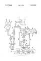
- the single FIGUREis a schematic diagram of a volume ventilator employing a demand regulator system in accordance with the present invention.
- the present inventionis described herein in conjunction with a volume ventilator of a particular configuration. However, it should be understood that the present invention is easily adaptable for use with a wide variety of medical ventilators of the type employing a positive displacement gas-delivery system (i.e., a piston or a bellows), and which have provision for spontaneous breathing.
- a positive displacement gas-delivery systemi.e., a piston or a bellows
- air and oxygenare respectively fed through a pair of regulators 10 and 12 and delivered to a blending or mixing device 14, where the gases are mixed to a proportion suitable for breathing by a patient (represented schematically and designated by the numeral 16).
- the blended gasis delivered through a check valve 18 to an inlet 20 of a chamber or cylinder 22 of predetermined maximum volume.
- a piston 24Operatively disposed within the cylinder 22 is a piston 24, the latter being actuated so as to reciprocate back and forth within the cylinder 22 by an electromechanical piston drive mechanism 26, of a type well-known in the art.
- the cylinder 22has an outlet 28 which communicates, via a check valve 30, with a inhalation conduit 32. Gas is delivered from the inhalation conduit 32 to the patient 16 via a suitable patient connection such as an endotracheal tube 34.
- the cylinder 22 and piston 24provide both a demand regulator function during spontaneous breathing and a breath-assist function when the ventilator is in its assist mode.
- the withdrawal of the piston 24 from the cylinder 22causes the cylinder 22 to be charged with a supply of gas from the mixing apparatus 14 via the check valve 18 and the inlet 20. This may be called the "negative pressure stroke" of the piston.
- the piston 24is caused to move forward within the cylinder 22 (i.e., the "positive pressure stroke"), the gas if forced out of the outlet 28, through the check valve 30 and into the patient's lungs via the inhalation conduit 32 and the endotracheal tube 34.
- the gas in the inhalation conduit 32is advantageously treated by a humidifier 36.
- a filter(not shown) may also be provided in the inhalation conduit 32 to remove dust and bacteria.
- exhalation conduit 38having an outlet port 40 enclosed within a variable pressure chamber 42, one wall of which forms a diaphragm 44 in registry with the outlet port 40.
- An exhalation control piston 46is located with respect to the diaphragm 44 so as alternately to flex the diaphragm to a position blocking the outlet port 40 when the piston 46 is in a forward position, and to release the diaphragm 44 and allow gas to flow out of the exhalation conduit 38 through the outlet port 40 when the piston 46 is in a retracted position.
- a piston control device 48such as a solenoid, is under the control of an output signal received from an assist control circuit, via line 51, in a manner to be described presently.
- the variable pressure chamber 42communicates with a reference pressure chamber 52 through a check valve 54 that permits gas flow only from the chamber 42 to the chamber 52.
- the pressure within the reference pressure chamber 52is positively maintained at a constant level by means of a gas jet source 56 that delivers a steady jet stream through a venturi 58 and into the chamber 52.
- a number of outlet orifices 60are located between the gas jet source 56 and the venturi 58 to allow gas exhaled by the patient to exit from the ventilator system.
- the gas jet source 56is adjustable within a range that permits the pressure inside the reference pressure chamber 52 to be set between approximately zero and fifteen centimeters of water (cmH 2 O) gauge.
- a bleeder line 62enables a backflow of gas from the reference pressure chamber 52 to enter the variable pressure chamber 42, with an adjustable valve 64 forming a restriction in the line 62 to limit the flow rate.
- the valve 64may be adjusted between fully opened and fully closed positions.
- Dynamic control of the ventilator, both in its assist and spontaneous modesbegins with a differential pressure transducer 65.
- the transducer 65is of a type which produces an analog electrical signal having an absolute value which is proportional to the magnitude of the pressure differential applied across the transducer, and a polarity which is indicative of the sign of that pressure differential (i.e., whether the pressure at a first pressure sensing input is greater than or less than the pressure at a second pressure sensing input).
- the transducer 65has a first side or pressure sensing input which receives the patient's airway proximal pressure from the conduit 38 via the variable pressure chamber 42 by means of a conduit 66, and a second side or pressure sensing input receptive to the pressure in the reference pressure chamber 52 via a conduit 68.
- the transducer 65has an electrical output line 70 which provides an electrical connection both to the assist control circuit 50 via a switch 72, and to a spontaneous breath servo circuit 74, via a branch line 76.
- the first side of the pressure transducer 65receives a variable, patient induced pressure via the exhalation conduit 38, variable pressure chamber 42, and first pressure input conduit 66 (assuming that the exhalation conduit outlet port 40 is uncovered by the diaphragm 44).
- the other side of the transducerreceives, via the second pressure input conduit 68, the pressure from the reverence pressure chamber 52, which is maintained at a substantially constant level, thereby providing a substantially constant reference pressure.
- the transducer 65will produce an output signal having a first polarity, indicative of incipient or ongoing inhalation, when the pressure in the variable chamber 42 (which is proportional to the airway proximal pressure of the patient) is less than the reference pressure in the chamber 52.
- the transducer 65will provide an output signal of a second polarity, indicative of incipient or ongoing exhalation, when the pressure in the chamber 42 exceeds that in chamber 52.
- the magnitude of the transducer output signalwill be proportional to the magnitude of the pressure differential between the two chambers.
- the transducer 65will yield a null signal.
- the transducer 65produces a signal having the first polarity and an absolute value which exceeds a predetermined signal threshold value. The signal so produced is transmitted to the assist control circuit 50 and to the spontaneous breath servo circuit 74 over the lines 70 and 76. The two latter circuits will then be actuated in a manner to be subsequently described.
- the reference pressure chamber 52may, in practice, be any source of a substantially constant reference pressure, preferably an adjustable one.
- the chamber 52is shown and described in conjunction with an exhalation apparatus of the type disclosed in U.S. Pat. No. 3,903,881 to Weigl and U.S. Pat. No. 4,141,356 to Smargiassi, both of these patents being commonly assigned with the present application.
- the purpose of this exhalation apparatusis threefold: (1) to establish an adjustable positive end expiratory pressure (PEEP); (2) to provide an adjustable reference pressure to the transducer 65 to control the action of the ventilator; and (3) to compensate for any leakages which may occur at the interface between the endotracheal tube 34 and the patient 16.
- PEEPpositive end expiratory pressure
- the reference pressure generating apparatusoperates as follows:
- the setting of the adjustable valve 64is normally determined by the expected voluntary inhalation flow rate produced by the patient. Gas flows through the bleeder line 62 should be substantially unrestricted by the valve 64 for flow rates that are substantially less than the expected inhalation rate. At such low flow rates, the flow through the bleeder line 62 is sufficient to substantially equalize the pressures in the chambers 42 and 52, thereby causing the pressure transducer 65 to produce a null signal. Larger backflows of gas are established from the chamber 42 to the patient 16 through the exhalation conduit 38 when the patient attempts to inhale.
- An inhalation attempt which yields at least the predetermined threshold level pressure differential between the chambers 42 and 52results in the generation, by the transducer 65, of an electrical signal having the aforesaid first polarity and a magnitude proportional to the pressure differential.
- This signalis applied to the assist control circuit 50 and the spontaneous breath servo circuit 74 over the lines 70 and 76.
- the assist control circuit 50may be any of a variety of types which actuate the piston 24, via the piston drive mechanism 26, so as to deliver an assisted breath in accordance with some predetermined regimen. An example of such a control circuit is disclosed in the aforementioned patent to Smargiassi.
- control circuit 50may be one which provides an actuation signal to the piston drive mechanism 26 after the reception of a programmable number of signals indicative of inhalation attempts from the transducer 65.
- the control circuit 50transmits an actuation signal to the piston drive mechanism 26 over a line 78, thereby causing the piston 24 to deliver an assisted breath to the patient with a positive pressure stroke, as described above.
- control circuit 50transmits a signal over line 51 to the exhalation piston control mechanism 48, which causes this mechanism to actuate the exhalation piston 46 so as to press the diaphragm 40 into a blocking engagement against the outlet port 40.
- the piston 24is caused to withdraw so as to refill the cylinder 22 with a fresh gas supply.
- Any breath attempt which does not initiate an actuation signal by the assist control circuit 50may be considered the initiation of a spontaneous breath by the patient.
- the output signal of the pressure transducer 65is an analog signal having an absolute value proportional to the magnitude of the pressure differential between the chambers 42 and 52.
- This output signalis received by the spontaneous breath servo circuit 74 over the line 76.
- the servo circuit 74will be enabled in response to an indicated spontaneous breath attempt. Such an attempt will be indicated by a signal over the line 76 having the aforementioned first polarity and an absolute value at or above a predetermined threshold value, which may be the same as or greater than the threshold value used to actuate the assist control 50.
- the servo circuit 74Upon the receipt of such a signal from the transducer 65, the servo circuit 74 will produce an electrical control signal which is fed along a line 80 to the piston drive mechanism 26.
- the control signal transmitted over line 80will have a magnitude proportional to the value of the input signal received from the pressure transducer 65.
- the piston drive mechanism 26is such that it drives the piston 24 forward, in a positive pressure stroke, with a speed which is proportional to the absolute value of the signal received from the servo circuit 74.
- the piston 24is driven so as to displace gas from the cylinder 22 at a rate which is directly proportional to the absolute value of the transducer output signal.
- the transducer output signalhas an absolute value which is directly proportional to the pressure differential between the chambers 42 and 52, which pressure differential is, in turn, a direct function of the patient's instantaneous inhalation effort.
- the piston 24is caused to displace gas from the cylinder 22 into the inhalation conduit 32, and from there to the patient at a rate which is an almost instantaneous function of the patient's demand.
- the piston 24is, in effect, "slaved" to the patient's demand, in that it strives to deliver gas at a rate which is sufficient to compensate for the deviation from the threshold level pressure differential caused by the patient's instantaneous inhalation effort.
- the action of the servo circuit 74, in conjunction with the drive mechanism 26,is such as to cause the delivery of gas by the piston 24 at a rate which substantially maintains the threshold level pressure differential.
- the piston's actionwill be slowed so that the rate of gas flow from the cylinder 22 is decreased.
- the pressure transducer 65yields the threshold level output signal, which causes the servo circuit 74 to respond by means of a control signal along the line 80, having a first predetermined value such that the drive mechanism stops the action of the piston.
- a transducer output signal having the second polaritybeing transmitted over lines 70 and 76.
- the servo circuit 74transmits a control signal over line 80 having a second predetermined value, such that the drive mechanism 26 causes the piston 24 to undergo a negative pressure stroke. If, however, the aforementioned predetermined time interval (as measured by, e.g., a conventional "clock circuit" within the servo circuit 76) has elapsed, the servo circuit 74 will transmit a control signal having the second predetermined value, even if the second polarity signal has not been received from the transducer 65. In either case, the cylinder 22 is recharged and ready to deliver either a spontaneous breath or an assisted breath, depending upon the type of command received by the drive mechanism 26.
- control circuit 50calls for an assisted breath, as previously described, it is desirable to disable the spontaneous breath servo circuit 74 so that the drive mechanism 26 cannot receive a potentially confusing signal from the latter circuit. This is accomplished by having the control circuit 50 transmit a blocking or disabling signal to the servo circuit 74 over a line 82 when the control circuit 50 actuates the assist mode.
- control circuit 50it may be desirable to disable the control circuit 50, so that the ventilator performs only in the spontaneous breathing mode, i.e., as a demand regulator. This is accomplished by opening the switch 72, thereby electrically isolating the control circuit 50 from the transducer 65, so that the former cannot be triggered by the latter to yield an assist mode actuation signal over the line 78, as previously described.
- a sensitivity adjustment control 84for the servo circuit 74.
- Such a controlcan assume any of a variety of types well-known in the art.
Landscapes
- Health & Medical Sciences (AREA)
- Emergency Medicine (AREA)
- Pulmonology (AREA)
- Engineering & Computer Science (AREA)
- Anesthesiology (AREA)
- Biomedical Technology (AREA)
- Heart & Thoracic Surgery (AREA)
- Hematology (AREA)
- Life Sciences & Earth Sciences (AREA)
- Animal Behavior & Ethology (AREA)
- General Health & Medical Sciences (AREA)
- Public Health (AREA)
- Veterinary Medicine (AREA)
- Measurement Of The Respiration, Hearing Ability, Form, And Blood Characteristics Of Living Organisms (AREA)
Abstract
Description
Claims (16)
Priority Applications (1)
| Application Number | Priority Date | Filing Date | Title |
|---|---|---|---|
| US06/417,621US4459982A (en) | 1982-09-13 | 1982-09-13 | Servo-controlled demand regulator for respiratory ventilator |
Applications Claiming Priority (1)
| Application Number | Priority Date | Filing Date | Title |
|---|---|---|---|
| US06/417,621US4459982A (en) | 1982-09-13 | 1982-09-13 | Servo-controlled demand regulator for respiratory ventilator |
Publications (1)
| Publication Number | Publication Date |
|---|---|
| US4459982Atrue US4459982A (en) | 1984-07-17 |
Family
ID=23654727
Family Applications (1)
| Application Number | Title | Priority Date | Filing Date |
|---|---|---|---|
| US06/417,621Expired - LifetimeUS4459982A (en) | 1982-09-13 | 1982-09-13 | Servo-controlled demand regulator for respiratory ventilator |
Country Status (1)
| Country | Link |
|---|---|
| US (1) | US4459982A (en) |
Cited By (80)
| Publication number | Priority date | Publication date | Assignee | Title |
|---|---|---|---|---|
| US4651731A (en)* | 1984-09-17 | 1987-03-24 | Figgie International Inc. | Self-contained portable single patient ventilator/resuscitator |
| WO1987002566A1 (en)* | 1985-10-25 | 1987-05-07 | Schulze Karl Frederick Jr | Method/apparatus for monitoring infants on assisted ventilation |
| US4744356A (en)* | 1986-03-03 | 1988-05-17 | Greenwood Eugene C | Demand oxygen supply device |
| WO1989003700A1 (en)* | 1985-10-02 | 1989-05-05 | Perkins Warren E | Method and means for dispensing a pre-measured volume of respirating gas |
| WO1989003699A1 (en)* | 1987-10-26 | 1989-05-05 | Perkins Warren E | Method and means for dispensing a pre-mesured volume of respirating gas |
| US4829998A (en)* | 1988-02-25 | 1989-05-16 | Jackson Richard R | Delivering breathable gas |
| US4838257A (en)* | 1987-07-17 | 1989-06-13 | Hatch Guy M | Ventilator |
| EP0283141A3 (en)* | 1987-02-21 | 1989-10-11 | University Of Manitoba | Lung ventilator device |
| US4898174A (en)* | 1988-05-03 | 1990-02-06 | Life Support Products, Inc. | Automatic ventilator |
| US4909246A (en)* | 1988-06-14 | 1990-03-20 | Dragerwerk Ag | Respirator with multiple inspiratory strokes |
| US4932401A (en)* | 1988-04-01 | 1990-06-12 | Perkins Warren E | Two-gas variable ratio, variable dose, metering system and method of use |
| US4967743A (en)* | 1987-03-11 | 1990-11-06 | Ballard Medical Products | Neonatal closed system for involuntary aspiration and ventilation, and method |
| US5065754A (en)* | 1990-06-06 | 1991-11-19 | Ballard Medical Products | Aspirating catheter tube inserter |
| US5072737A (en)* | 1989-04-12 | 1991-12-17 | Puritan-Bennett Corporation | Method and apparatus for metabolic monitoring |
| US5072729A (en)* | 1986-11-04 | 1991-12-17 | Bird Products Corporation | Ventilator exhalation valve |
| US5101820A (en)* | 1989-11-02 | 1992-04-07 | Christopher Kent L | Apparatus for high continuous flow augmentation of ventilation and method therefor |
| US5107829A (en)* | 1987-03-11 | 1992-04-28 | Ballard Medical Products | Neonatal closed system for involuntary aspiration and ventilation, and method |
| DE4038871A1 (en)* | 1990-12-03 | 1992-06-04 | Peter Dr Sc Techn Schaller | Respirator control using sensor to measure breath vol. or flow - and supplying signal processor also receiving resistance, inverse compliance and any leakage vol. values as well as threshold values to control breathing pressure |
| US5133345A (en)* | 1987-03-11 | 1992-07-28 | Ballard Medical Products | Neonatal closed system for involuntary aspiration and ventilation, and method |
| US5165397A (en)* | 1988-12-15 | 1992-11-24 | Arp Leon J | Method and apparatus for demand oxygen system monitoring and control |
| US5215522A (en)* | 1984-07-23 | 1993-06-01 | Ballard Medical Products | Single use medical aspirating device and method |
| US5277177A (en)* | 1984-07-23 | 1994-01-11 | Ballard Medical Products | Single use medical aspirating device and method |
| US5303698A (en)* | 1991-08-27 | 1994-04-19 | The Boc Group, Inc. | Medical ventilator |
| US5438980A (en)* | 1993-01-12 | 1995-08-08 | Puritan-Bennett Corporation | Inhalation/exhalation respiratory phase detection circuit |
| DE19528113A1 (en)* | 1995-08-01 | 1997-02-06 | Univ Ludwigs Albert | Artificial respiration unit for controlled mechanical artificial respiration - has endotracheal tube and respirator also breathing gas flowmeter at which evaluator unit is connected with integrator for integrating gas flow to breathing gas vol |
| US5664563A (en)* | 1994-12-09 | 1997-09-09 | Cardiopulmonary Corporation | Pneumatic system |
| US5673689A (en)* | 1995-02-09 | 1997-10-07 | Puritan Bennett Corporation | Piston based ventilator |
| US5694926A (en)* | 1994-10-14 | 1997-12-09 | Bird Products Corporation | Portable drag compressor powered mechanical ventilator |
| US5694922A (en) | 1994-05-18 | 1997-12-09 | Ballard Medical Products | Swivel tube connections with hermetic seals |
| WO1999020332A1 (en) | 1997-10-20 | 1999-04-29 | Christopher Kent L | System for monitoring and treating sleep disorders using a transtracheal catheter |
| US6135967A (en)* | 1999-04-26 | 2000-10-24 | Fiorenza; Anthony Joseph | Respiratory ventilator with automatic flow calibration |
| DE19921917A1 (en)* | 1999-05-12 | 2000-12-14 | Michael Lerch | Control of the amount of enriching oxygen delivered to a user so that enrichment levels are matched to requirements by use of a carbon dioxide sensor, blood oxygen level sensor, etc. and controlling electronics |
| EP1103279A2 (en) | 1990-03-30 | 2001-05-30 | The University Of Manitoba | Lung ventilator device |
| US6240919B1 (en) | 1999-06-07 | 2001-06-05 | Macdonald John J. | Method for providing respiratory airway support pressure |
| US6457472B1 (en) | 1996-12-12 | 2002-10-01 | The Johns Hopkins University | Method and apparatus for providing ventilatory support to a patient |
| US6463930B2 (en)* | 1995-12-08 | 2002-10-15 | James W. Biondi | System for automatically weaning a patient from a ventilator, and method thereof |
| US6494203B1 (en) | 1994-08-19 | 2002-12-17 | Ballard Medical Products | Medical aspirating/ventilating closed system improvements and methods |
| EP1491226A1 (en)* | 2003-06-27 | 2004-12-29 | Weinmann Geräte für Medizin GmbH & Co. KG | Method for humidification of a respiratory gas and a respiratory device |
| US20050192538A1 (en)* | 2004-02-26 | 2005-09-01 | Voege James A. | Method and apparatus for regulating fluid flow or conserving fluid flow |
| US20070193579A1 (en)* | 2006-02-21 | 2007-08-23 | Viasys Manufacturing, Inc. | Hardware configuration for pressure driver |
| US20080168989A1 (en)* | 2004-11-11 | 2008-07-17 | Goran Cewers | Expiratory Pressure Regulation in a Ventilator |
| US20080202520A1 (en)* | 2007-02-23 | 2008-08-28 | General Electric Company | Setting mandatory mechanical ventilation parameters based on patient physiology |
| US20080202519A1 (en)* | 2007-02-23 | 2008-08-28 | General Electric Company | Setting mandatory mechanical ventilation parameters based on patient physiology |
| US20080202525A1 (en)* | 2007-02-23 | 2008-08-28 | General Electric Company | Setting mandatory mechanical ventilation parameters based on patient physiology |
| US20080202517A1 (en)* | 2007-02-23 | 2008-08-28 | General Electric Company | Setting madatory mechanical ventilation parameters based on patient physiology |
| US20080202518A1 (en)* | 2007-02-23 | 2008-08-28 | General Electric Company | Setting mandatory mechanical ventilation parameters based on patient physiology |
| US20080230064A1 (en)* | 2007-03-23 | 2008-09-25 | General Electric Company | Setting inspiratory time in mandatory mechanical ventilation based on patient physiology, such as when forced inhalation flow ceases |
| US20080230063A1 (en)* | 2007-03-23 | 2008-09-25 | General Electric Company | Setting inspiratory time in mandatory mechanical ventilation based on patient physiology, such as forced inhalation time |
| US20080230060A1 (en)* | 2007-03-23 | 2008-09-25 | General Electric Company | Setting inspiratory time in mandatory mechanical ventilation based on patient physiology, such as when tidal volume is inspired |
| US20080230061A1 (en)* | 2007-03-23 | 2008-09-25 | General Electric Company | Setting expiratory time in mandatory mechanical ventilation based on a deviation from a stable condition of end tidal gas concentrations |
| US7448594B2 (en) | 2004-10-21 | 2008-11-11 | Ameriflo, Inc. | Fluid regulator |
| US20090014001A1 (en)* | 2007-06-29 | 2009-01-15 | Helge Myklebust | Method and apparatus for providing ventilation and perfusion |
| US7617826B1 (en) | 2004-02-26 | 2009-11-17 | Ameriflo, Inc. | Conserver |
| US20100043789A1 (en)* | 2008-08-21 | 2010-02-25 | Fine David H | Systems for generating nitric oxide |
| US20100139660A1 (en)* | 2008-12-10 | 2010-06-10 | Carmeli Adahan | Pump and exhalation valve control for respirator apparatus |
| US8226597B2 (en) | 2002-06-21 | 2012-07-24 | Baxter International, Inc. | Fluid delivery system and flow control therefor |
| US8844526B2 (en) | 2012-03-30 | 2014-09-30 | Covidien Lp | Methods and systems for triggering with unknown base flow |
| US9022031B2 (en) | 2012-01-31 | 2015-05-05 | Covidien Lp | Using estimated carinal pressure for feedback control of carinal pressure during ventilation |
| US9027552B2 (en) | 2012-07-31 | 2015-05-12 | Covidien Lp | Ventilator-initiated prompt or setting regarding detection of asynchrony during ventilation |
| US20160051780A1 (en)* | 2003-07-17 | 2016-02-25 | Zoll Medical Corporation | Automatic Patient Ventilator System and Method |
| US9364624B2 (en) | 2011-12-07 | 2016-06-14 | Covidien Lp | Methods and systems for adaptive base flow |
| US9492629B2 (en) | 2013-02-14 | 2016-11-15 | Covidien Lp | Methods and systems for ventilation with unknown exhalation flow and exhalation pressure |
| US9498589B2 (en) | 2011-12-31 | 2016-11-22 | Covidien Lp | Methods and systems for adaptive base flow and leak compensation |
| US9649458B2 (en) | 2008-09-30 | 2017-05-16 | Covidien Lp | Breathing assistance system with multiple pressure sensors |
| US9808591B2 (en) | 2014-08-15 | 2017-11-07 | Covidien Lp | Methods and systems for breath delivery synchronization |
| US9925346B2 (en) | 2015-01-20 | 2018-03-27 | Covidien Lp | Systems and methods for ventilation with unknown exhalation flow |
| US9950129B2 (en) | 2014-10-27 | 2018-04-24 | Covidien Lp | Ventilation triggering using change-point detection |
| US9956371B2 (en) | 2015-03-24 | 2018-05-01 | Ventec Life Systems, Inc. | Ventilator with integrated cough-assist |
| US9981096B2 (en) | 2013-03-13 | 2018-05-29 | Covidien Lp | Methods and systems for triggering with unknown inspiratory flow |
| US9993604B2 (en) | 2012-04-27 | 2018-06-12 | Covidien Lp | Methods and systems for an optimized proportional assist ventilation |
| US10362967B2 (en) | 2012-07-09 | 2019-07-30 | Covidien Lp | Systems and methods for missed breath detection and indication |
| US10773049B2 (en) | 2016-06-21 | 2020-09-15 | Ventec Life Systems, Inc. | Cough-assist systems with humidifier bypass |
| CN113133759A (en)* | 2021-04-08 | 2021-07-20 | 贵州宇悦生命科技股份有限公司 | Respiration-assisted health monitoring system based on big data and use control method |
| US11191915B2 (en) | 2018-05-13 | 2021-12-07 | Ventec Life Systems, Inc. | Portable medical ventilator system using portable oxygen concentrators |
| US11247015B2 (en) | 2015-03-24 | 2022-02-15 | Ventec Life Systems, Inc. | Ventilator with integrated oxygen production |
| US11324954B2 (en) | 2019-06-28 | 2022-05-10 | Covidien Lp | Achieving smooth breathing by modified bilateral phrenic nerve pacing |
| US20220370753A1 (en)* | 2005-07-01 | 2022-11-24 | Fisher & Paykel Healthcare Limited | Breathing assistance apparatus with a manifold to add auxiliary gases to ambient gases |
| US12121655B2 (en) | 2020-04-30 | 2024-10-22 | Karim Salehpoor | Active lung assist device |
| US12257437B2 (en) | 2020-09-30 | 2025-03-25 | Covidien Lp | Intravenous phrenic nerve stimulation lead |
| US12440634B2 (en) | 2021-12-21 | 2025-10-14 | Ventec Life Systems, Inc. | Ventilator systems with integrated oxygen delivery, and associated devices and methods |
Citations (14)
| Publication number | Priority date | Publication date | Assignee | Title |
|---|---|---|---|---|
| US3903881A (en)* | 1974-04-12 | 1975-09-09 | Bourns Inc | Respirator system and method |
| US3905362A (en)* | 1973-10-02 | 1975-09-16 | Chemetron Corp | Volume-rate respirator system and method |
| US3916888A (en)* | 1973-10-04 | 1975-11-04 | Tecna Corp | Respirator |
| US3916889A (en)* | 1973-09-28 | 1975-11-04 | Sandoz Ag | Patient ventilator apparatus |
| US3932066A (en)* | 1973-10-02 | 1976-01-13 | Chemetron Corporation | Breathing gas delivery cylinder for respirators |
| US3951137A (en)* | 1974-11-20 | 1976-04-20 | The United States Of America As Represented By The Secretary Of The Air Force | Rebreathing system |
| US3961627A (en)* | 1973-09-07 | 1976-06-08 | Hoffmann-La Roche Inc. | Automatic regulation of respirators |
| US3972327A (en)* | 1973-03-22 | 1976-08-03 | Hoffmann-La Roche Inc. | Respirator |
| US4001700A (en)* | 1974-04-16 | 1977-01-04 | Sutter Hospitals Medical Research Foundation | Digital waveform generator for automatic respiratory ventilators |
| US4036221A (en)* | 1972-05-01 | 1977-07-19 | Sutter Hospitals Medical Research Foundation | Respirator |
| US4141356A (en)* | 1976-06-16 | 1979-02-27 | Bourns, Inc. | Respirator system and method |
| US4210136A (en)* | 1977-07-14 | 1980-07-01 | Apple Wayne R | Apparatus for automatic ventilation of the lungs |
| US4357936A (en)* | 1979-03-05 | 1982-11-09 | Bear Medical Systems, Inc. | Directional thermistor assist sensing |
| US4393869A (en)* | 1981-06-22 | 1983-07-19 | Canadian Patents & Development Limited | Electronically controlled respirator |
- 1982
- 1982-09-13USUS06/417,621patent/US4459982A/ennot_activeExpired - Lifetime
Patent Citations (14)
| Publication number | Priority date | Publication date | Assignee | Title |
|---|---|---|---|---|
| US4036221A (en)* | 1972-05-01 | 1977-07-19 | Sutter Hospitals Medical Research Foundation | Respirator |
| US3972327A (en)* | 1973-03-22 | 1976-08-03 | Hoffmann-La Roche Inc. | Respirator |
| US3961627A (en)* | 1973-09-07 | 1976-06-08 | Hoffmann-La Roche Inc. | Automatic regulation of respirators |
| US3916889A (en)* | 1973-09-28 | 1975-11-04 | Sandoz Ag | Patient ventilator apparatus |
| US3932066A (en)* | 1973-10-02 | 1976-01-13 | Chemetron Corporation | Breathing gas delivery cylinder for respirators |
| US3905362A (en)* | 1973-10-02 | 1975-09-16 | Chemetron Corp | Volume-rate respirator system and method |
| US3916888A (en)* | 1973-10-04 | 1975-11-04 | Tecna Corp | Respirator |
| US3903881A (en)* | 1974-04-12 | 1975-09-09 | Bourns Inc | Respirator system and method |
| US4001700A (en)* | 1974-04-16 | 1977-01-04 | Sutter Hospitals Medical Research Foundation | Digital waveform generator for automatic respiratory ventilators |
| US3951137A (en)* | 1974-11-20 | 1976-04-20 | The United States Of America As Represented By The Secretary Of The Air Force | Rebreathing system |
| US4141356A (en)* | 1976-06-16 | 1979-02-27 | Bourns, Inc. | Respirator system and method |
| US4210136A (en)* | 1977-07-14 | 1980-07-01 | Apple Wayne R | Apparatus for automatic ventilation of the lungs |
| US4357936A (en)* | 1979-03-05 | 1982-11-09 | Bear Medical Systems, Inc. | Directional thermistor assist sensing |
| US4393869A (en)* | 1981-06-22 | 1983-07-19 | Canadian Patents & Development Limited | Electronically controlled respirator |
Cited By (143)
| Publication number | Priority date | Publication date | Assignee | Title |
|---|---|---|---|---|
| US5611336A (en)* | 1984-07-23 | 1997-03-18 | Ballard Medical Products, Inc. | Single use medical aspirating device and method |
| US5277177A (en)* | 1984-07-23 | 1994-01-11 | Ballard Medical Products | Single use medical aspirating device and method |
| US5215522A (en)* | 1984-07-23 | 1993-06-01 | Ballard Medical Products | Single use medical aspirating device and method |
| US4651731A (en)* | 1984-09-17 | 1987-03-24 | Figgie International Inc. | Self-contained portable single patient ventilator/resuscitator |
| WO1989003700A1 (en)* | 1985-10-02 | 1989-05-05 | Perkins Warren E | Method and means for dispensing a pre-measured volume of respirating gas |
| WO1987002566A1 (en)* | 1985-10-25 | 1987-05-07 | Schulze Karl Frederick Jr | Method/apparatus for monitoring infants on assisted ventilation |
| US4671297A (en)* | 1985-10-25 | 1987-06-09 | Schulze Jr Karl F | Method and apparatus for monitoring infants on assisted ventilation |
| US4744356A (en)* | 1986-03-03 | 1988-05-17 | Greenwood Eugene C | Demand oxygen supply device |
| US5072729A (en)* | 1986-11-04 | 1991-12-17 | Bird Products Corporation | Ventilator exhalation valve |
| US5044362A (en)* | 1987-02-21 | 1991-09-03 | University Of Manitoba | Lung ventilator device |
| EP0283141A3 (en)* | 1987-02-21 | 1989-10-11 | University Of Manitoba | Lung ventilator device |
| US5107830A (en)* | 1987-02-21 | 1992-04-28 | University Of Manitoba | Lung ventilator device |
| US4967743A (en)* | 1987-03-11 | 1990-11-06 | Ballard Medical Products | Neonatal closed system for involuntary aspiration and ventilation, and method |
| US5107829A (en)* | 1987-03-11 | 1992-04-28 | Ballard Medical Products | Neonatal closed system for involuntary aspiration and ventilation, and method |
| US5133345A (en)* | 1987-03-11 | 1992-07-28 | Ballard Medical Products | Neonatal closed system for involuntary aspiration and ventilation, and method |
| US4838257A (en)* | 1987-07-17 | 1989-06-13 | Hatch Guy M | Ventilator |
| WO1989003699A1 (en)* | 1987-10-26 | 1989-05-05 | Perkins Warren E | Method and means for dispensing a pre-mesured volume of respirating gas |
| US4829998A (en)* | 1988-02-25 | 1989-05-16 | Jackson Richard R | Delivering breathable gas |
| US4932401A (en)* | 1988-04-01 | 1990-06-12 | Perkins Warren E | Two-gas variable ratio, variable dose, metering system and method of use |
| US4898174A (en)* | 1988-05-03 | 1990-02-06 | Life Support Products, Inc. | Automatic ventilator |
| US4909246A (en)* | 1988-06-14 | 1990-03-20 | Dragerwerk Ag | Respirator with multiple inspiratory strokes |
| US5165397A (en)* | 1988-12-15 | 1992-11-24 | Arp Leon J | Method and apparatus for demand oxygen system monitoring and control |
| US5072737A (en)* | 1989-04-12 | 1991-12-17 | Puritan-Bennett Corporation | Method and apparatus for metabolic monitoring |
| US5101820A (en)* | 1989-11-02 | 1992-04-07 | Christopher Kent L | Apparatus for high continuous flow augmentation of ventilation and method therefor |
| EP1103279A2 (en) | 1990-03-30 | 2001-05-30 | The University Of Manitoba | Lung ventilator device |
| US5065754A (en)* | 1990-06-06 | 1991-11-19 | Ballard Medical Products | Aspirating catheter tube inserter |
| DE4038871A1 (en)* | 1990-12-03 | 1992-06-04 | Peter Dr Sc Techn Schaller | Respirator control using sensor to measure breath vol. or flow - and supplying signal processor also receiving resistance, inverse compliance and any leakage vol. values as well as threshold values to control breathing pressure |
| US5303698A (en)* | 1991-08-27 | 1994-04-19 | The Boc Group, Inc. | Medical ventilator |
| US5438980A (en)* | 1993-01-12 | 1995-08-08 | Puritan-Bennett Corporation | Inhalation/exhalation respiratory phase detection circuit |
| US5694922A (en) | 1994-05-18 | 1997-12-09 | Ballard Medical Products | Swivel tube connections with hermetic seals |
| US6494203B1 (en) | 1994-08-19 | 2002-12-17 | Ballard Medical Products | Medical aspirating/ventilating closed system improvements and methods |
| US5694926A (en)* | 1994-10-14 | 1997-12-09 | Bird Products Corporation | Portable drag compressor powered mechanical ventilator |
| US6877511B2 (en) | 1994-10-14 | 2005-04-12 | Bird Products Corporation | Portable drag compressor powered mechanical ventilator |
| US5868133A (en)* | 1994-10-14 | 1999-02-09 | Bird Products Corporation | Portable drag compressor powered mechanical ventilator |
| US5881722A (en)* | 1994-10-14 | 1999-03-16 | Bird Products Corporation | Portable drag compressor powered mechanical ventilator |
| US7849854B2 (en)* | 1994-10-14 | 2010-12-14 | Bird Products Corporation | Portable drag compressor powered mechanical ventilator |
| US6526970B2 (en) | 1994-10-14 | 2003-03-04 | Devries Douglas F. | Portable drag compressor powered mechanical ventilator |
| US20050150494A1 (en)* | 1994-10-14 | 2005-07-14 | Devries Douglas F. | Portable drag compressor powered mechanical ventilator |
| US20030230307A1 (en)* | 1994-10-14 | 2003-12-18 | Devries Douglas F. | Portable drag compressor powered mechanical ventilator |
| US7222623B2 (en) | 1994-10-14 | 2007-05-29 | Birds Products Corporation | Portable drag compressor powered mechanical ventilator |
| US5664563A (en)* | 1994-12-09 | 1997-09-09 | Cardiopulmonary Corporation | Pneumatic system |
| US5673689A (en)* | 1995-02-09 | 1997-10-07 | Puritan Bennett Corporation | Piston based ventilator |
| US5915382A (en)* | 1995-02-09 | 1999-06-29 | Puritan-Bennett Corporation | Piston based ventillator |
| DE19528113A1 (en)* | 1995-08-01 | 1997-02-06 | Univ Ludwigs Albert | Artificial respiration unit for controlled mechanical artificial respiration - has endotracheal tube and respirator also breathing gas flowmeter at which evaluator unit is connected with integrator for integrating gas flow to breathing gas vol |
| DE19528113C2 (en)* | 1995-08-01 | 2002-09-12 | Univ Ludwigs Albert | ventilator |
| US20050051167A1 (en)* | 1995-12-08 | 2005-03-10 | Biondi James W. | System for automatically weaning a patient from a ventilator, and method thereof |
| US6463930B2 (en)* | 1995-12-08 | 2002-10-15 | James W. Biondi | System for automatically weaning a patient from a ventilator, and method thereof |
| US7017574B2 (en) | 1995-12-08 | 2006-03-28 | Cardiopulmonary Corporation | System for automatically weaning a patient from a ventilator, and method thereof |
| US6668829B2 (en)* | 1995-12-08 | 2003-12-30 | Cardiopulmonary Corporation | System for automatically weaning a patient from a ventilator, and method thereof |
| US7334578B2 (en) | 1995-12-08 | 2008-02-26 | Cardiopulmonary Corporation | System for automatically weaning a patient from a ventilator, and method thereof |
| US6457472B1 (en) | 1996-12-12 | 2002-10-01 | The Johns Hopkins University | Method and apparatus for providing ventilatory support to a patient |
| US5954050A (en)* | 1997-10-20 | 1999-09-21 | Christopher; Kent L. | System for monitoring and treating sleep disorders using a transtracheal catheter |
| WO1999020332A1 (en) | 1997-10-20 | 1999-04-29 | Christopher Kent L | System for monitoring and treating sleep disorders using a transtracheal catheter |
| US6135967A (en)* | 1999-04-26 | 2000-10-24 | Fiorenza; Anthony Joseph | Respiratory ventilator with automatic flow calibration |
| DE19921917A1 (en)* | 1999-05-12 | 2000-12-14 | Michael Lerch | Control of the amount of enriching oxygen delivered to a user so that enrichment levels are matched to requirements by use of a carbon dioxide sensor, blood oxygen level sensor, etc. and controlling electronics |
| US6240919B1 (en) | 1999-06-07 | 2001-06-05 | Macdonald John J. | Method for providing respiratory airway support pressure |
| US8226597B2 (en) | 2002-06-21 | 2012-07-24 | Baxter International, Inc. | Fluid delivery system and flow control therefor |
| US8672876B2 (en) | 2002-06-21 | 2014-03-18 | Baxter International Inc. | Fluid delivery system and flow control therefor |
| US8231566B2 (en) | 2002-06-21 | 2012-07-31 | Baxter International, Inc. | Fluid delivery system and flow control therefor |
| EP1491226A1 (en)* | 2003-06-27 | 2004-12-29 | Weinmann Geräte für Medizin GmbH & Co. KG | Method for humidification of a respiratory gas and a respiratory device |
| US11596753B2 (en)* | 2003-07-17 | 2023-03-07 | Zoll Medical Corporation | Automatic patient ventilator system and method |
| US20160051780A1 (en)* | 2003-07-17 | 2016-02-25 | Zoll Medical Corporation | Automatic Patient Ventilator System and Method |
| US8146592B2 (en) | 2004-02-26 | 2012-04-03 | Ameriflo, Inc. | Method and apparatus for regulating fluid flow or conserving fluid flow |
| US7617826B1 (en) | 2004-02-26 | 2009-11-17 | Ameriflo, Inc. | Conserver |
| US8230859B1 (en) | 2004-02-26 | 2012-07-31 | Ameriflo, Inc. | Method and apparatus for regulating fluid |
| US20050192538A1 (en)* | 2004-02-26 | 2005-09-01 | Voege James A. | Method and apparatus for regulating fluid flow or conserving fluid flow |
| US7448594B2 (en) | 2004-10-21 | 2008-11-11 | Ameriflo, Inc. | Fluid regulator |
| US20080168989A1 (en)* | 2004-11-11 | 2008-07-17 | Goran Cewers | Expiratory Pressure Regulation in a Ventilator |
| US8230857B2 (en)* | 2004-11-11 | 2012-07-31 | Ric Investments, Llc. | Expiratory pressure regulation in a ventilator |
| US20220370753A1 (en)* | 2005-07-01 | 2022-11-24 | Fisher & Paykel Healthcare Limited | Breathing assistance apparatus with a manifold to add auxiliary gases to ambient gases |
| US12156970B2 (en)* | 2005-07-01 | 2024-12-03 | Fisher & Paykel Healthcare Limited | Breathing assistance apparatus with a manifold to add auxiliary gases to ambient gases |
| US12083282B2 (en) | 2005-07-01 | 2024-09-10 | Fisher & Paykel Healthcare Limited | Breathing assistance apparatus with a manifold to add auxiliary gases to ambient gases |
| US11666726B2 (en) | 2005-07-01 | 2023-06-06 | Fisher & Paykel Healthcare Limited | Breathing assistance apparatus with a manifold to add auxiliary gases to ambient gases |
| US20070193579A1 (en)* | 2006-02-21 | 2007-08-23 | Viasys Manufacturing, Inc. | Hardware configuration for pressure driver |
| US7509957B2 (en)* | 2006-02-21 | 2009-03-31 | Viasys Manufacturing, Inc. | Hardware configuration for pressure driver |
| US20080202520A1 (en)* | 2007-02-23 | 2008-08-28 | General Electric Company | Setting mandatory mechanical ventilation parameters based on patient physiology |
| US20080202523A1 (en)* | 2007-02-23 | 2008-08-28 | General Electric Company | Setting mandatory mechanical ventilation parameters based on patient physiology |
| US20080202521A1 (en)* | 2007-02-23 | 2008-08-28 | General Electric Company | Setting mandatory mechanical ventilation parameters based on patient physiology |
| US20080202518A1 (en)* | 2007-02-23 | 2008-08-28 | General Electric Company | Setting mandatory mechanical ventilation parameters based on patient physiology |
| US20080202517A1 (en)* | 2007-02-23 | 2008-08-28 | General Electric Company | Setting madatory mechanical ventilation parameters based on patient physiology |
| US20080202522A1 (en)* | 2007-02-23 | 2008-08-28 | General Electric Company | Setting mandatory mechanical ventilation parameters based on patient physiology |
| US20080202524A1 (en)* | 2007-02-23 | 2008-08-28 | General Electric Company | Setting madatory mechanical ventilation parameters based on patient physiology |
| US20080202525A1 (en)* | 2007-02-23 | 2008-08-28 | General Electric Company | Setting mandatory mechanical ventilation parameters based on patient physiology |
| US20080202519A1 (en)* | 2007-02-23 | 2008-08-28 | General Electric Company | Setting mandatory mechanical ventilation parameters based on patient physiology |
| US20080230060A1 (en)* | 2007-03-23 | 2008-09-25 | General Electric Company | Setting inspiratory time in mandatory mechanical ventilation based on patient physiology, such as when tidal volume is inspired |
| US20080230064A1 (en)* | 2007-03-23 | 2008-09-25 | General Electric Company | Setting inspiratory time in mandatory mechanical ventilation based on patient physiology, such as when forced inhalation flow ceases |
| US20080230061A1 (en)* | 2007-03-23 | 2008-09-25 | General Electric Company | Setting expiratory time in mandatory mechanical ventilation based on a deviation from a stable condition of end tidal gas concentrations |
| US20080230063A1 (en)* | 2007-03-23 | 2008-09-25 | General Electric Company | Setting inspiratory time in mandatory mechanical ventilation based on patient physiology, such as forced inhalation time |
| US20090014001A1 (en)* | 2007-06-29 | 2009-01-15 | Helge Myklebust | Method and apparatus for providing ventilation and perfusion |
| US20100043789A1 (en)* | 2008-08-21 | 2010-02-25 | Fine David H | Systems for generating nitric oxide |
| US8701657B2 (en)* | 2008-08-21 | 2014-04-22 | Geno Llc | Systems for generating nitric oxide |
| US9649458B2 (en) | 2008-09-30 | 2017-05-16 | Covidien Lp | Breathing assistance system with multiple pressure sensors |
| US8303276B2 (en)* | 2008-12-10 | 2012-11-06 | Covidien Lp | Pump and exhalation valve control for respirator apparatus |
| WO2010068324A1 (en)* | 2008-12-10 | 2010-06-17 | Newport Medical Instruments, Inc. | Pump exhalation valve control for respirator apparatus |
| US20100139660A1 (en)* | 2008-12-10 | 2010-06-10 | Carmeli Adahan | Pump and exhalation valve control for respirator apparatus |
| US11497869B2 (en) | 2011-12-07 | 2022-11-15 | Covidien Lp | Methods and systems for adaptive base flow |
| US9364624B2 (en) | 2011-12-07 | 2016-06-14 | Covidien Lp | Methods and systems for adaptive base flow |
| US10543327B2 (en) | 2011-12-07 | 2020-01-28 | Covidien Lp | Methods and systems for adaptive base flow |
| US9498589B2 (en) | 2011-12-31 | 2016-11-22 | Covidien Lp | Methods and systems for adaptive base flow and leak compensation |
| US10709854B2 (en) | 2011-12-31 | 2020-07-14 | Covidien Lp | Methods and systems for adaptive base flow and leak compensation |
| US11833297B2 (en) | 2011-12-31 | 2023-12-05 | Covidien Lp | Methods and systems for adaptive base flow and leak compensation |
| US9022031B2 (en) | 2012-01-31 | 2015-05-05 | Covidien Lp | Using estimated carinal pressure for feedback control of carinal pressure during ventilation |
| US8844526B2 (en) | 2012-03-30 | 2014-09-30 | Covidien Lp | Methods and systems for triggering with unknown base flow |
| US10029057B2 (en) | 2012-03-30 | 2018-07-24 | Covidien Lp | Methods and systems for triggering with unknown base flow |
| US9993604B2 (en) | 2012-04-27 | 2018-06-12 | Covidien Lp | Methods and systems for an optimized proportional assist ventilation |
| US10806879B2 (en) | 2012-04-27 | 2020-10-20 | Covidien Lp | Methods and systems for an optimized proportional assist ventilation |
| US11642042B2 (en) | 2012-07-09 | 2023-05-09 | Covidien Lp | Systems and methods for missed breath detection and indication |
| US10362967B2 (en) | 2012-07-09 | 2019-07-30 | Covidien Lp | Systems and methods for missed breath detection and indication |
| US9027552B2 (en) | 2012-07-31 | 2015-05-12 | Covidien Lp | Ventilator-initiated prompt or setting regarding detection of asynchrony during ventilation |
| US9492629B2 (en) | 2013-02-14 | 2016-11-15 | Covidien Lp | Methods and systems for ventilation with unknown exhalation flow and exhalation pressure |
| US9981096B2 (en) | 2013-03-13 | 2018-05-29 | Covidien Lp | Methods and systems for triggering with unknown inspiratory flow |
| US9808591B2 (en) | 2014-08-15 | 2017-11-07 | Covidien Lp | Methods and systems for breath delivery synchronization |
| US10864336B2 (en) | 2014-08-15 | 2020-12-15 | Covidien Lp | Methods and systems for breath delivery synchronization |
| US9950129B2 (en) | 2014-10-27 | 2018-04-24 | Covidien Lp | Ventilation triggering using change-point detection |
| US11712174B2 (en) | 2014-10-27 | 2023-08-01 | Covidien Lp | Ventilation triggering |
| US10940281B2 (en) | 2014-10-27 | 2021-03-09 | Covidien Lp | Ventilation triggering |
| US9925346B2 (en) | 2015-01-20 | 2018-03-27 | Covidien Lp | Systems and methods for ventilation with unknown exhalation flow |
| US10105509B2 (en) | 2015-03-24 | 2018-10-23 | Ventec Life Systems, Inc. | Active exhalation valve |
| US11185655B2 (en) | 2015-03-24 | 2021-11-30 | Ventec Life Systems, Inc. | Passive leak valve |
| US10758699B2 (en) | 2015-03-24 | 2020-09-01 | Ventec Life Systems, Inc. | Secretion trap |
| US11247015B2 (en) | 2015-03-24 | 2022-02-15 | Ventec Life Systems, Inc. | Ventilator with integrated oxygen production |
| US11291791B2 (en) | 2015-03-24 | 2022-04-05 | Ventee Life Systems, Inc. | Ventilator with integrated cough-assist |
| US9956371B2 (en) | 2015-03-24 | 2018-05-01 | Ventec Life Systems, Inc. | Ventilator with integrated cough-assist |
| US11344692B2 (en) | 2015-03-24 | 2022-05-31 | Ventec Life Systems, Inc. | Respiratory therapy systems and methods |
| US10576237B2 (en) | 2015-03-24 | 2020-03-03 | Ventec Life Systems, Inc. | Active exhalation valve |
| US10518059B2 (en) | 2015-03-24 | 2019-12-31 | Ventec Life Systems, Inc. | Passive leak valve |
| US10315002B2 (en) | 2015-03-24 | 2019-06-11 | Ventec Life Systems, Inc. | Ventilator with integrated oxygen production |
| US10245406B2 (en) | 2015-03-24 | 2019-04-02 | Ventec Life Systems, Inc. | Ventilator with integrated oxygen production |
| US11992619B2 (en) | 2015-03-24 | 2024-05-28 | Ventec Life Systems, Inc. | Ventilator with integrated cough-assist |
| US10046134B2 (en) | 2015-03-24 | 2018-08-14 | Ventec Life Systems, Inc. | Pressure swing adsorption oxygen generator |
| US11679229B2 (en) | 2016-06-21 | 2023-06-20 | Ventec Life Systems, Inc. | Cough-assist systems with humidifier bypass |
| US10773049B2 (en) | 2016-06-21 | 2020-09-15 | Ventec Life Systems, Inc. | Cough-assist systems with humidifier bypass |
| US12246135B2 (en) | 2016-06-21 | 2025-03-11 | Ventec Life Systems, Inc. | Cough-assist systems with humidifier bypass |
| US11191915B2 (en) | 2018-05-13 | 2021-12-07 | Ventec Life Systems, Inc. | Portable medical ventilator system using portable oxygen concentrators |
| US12370333B2 (en) | 2018-05-13 | 2025-07-29 | Ventec Life Systems, Inc. | Portable medical ventilator system using portable oxygen concentrators |
| US12434026B2 (en) | 2018-05-13 | 2025-10-07 | Ventec Life Systems, Inc. | Portable medical ventilator system using portable oxygen concentrators |
| US12036409B2 (en) | 2019-06-28 | 2024-07-16 | Covidien Lp | Achieving smooth breathing by modified bilateral phrenic nerve pacing |
| US11324954B2 (en) | 2019-06-28 | 2022-05-10 | Covidien Lp | Achieving smooth breathing by modified bilateral phrenic nerve pacing |
| US12121655B2 (en) | 2020-04-30 | 2024-10-22 | Karim Salehpoor | Active lung assist device |
| US12257437B2 (en) | 2020-09-30 | 2025-03-25 | Covidien Lp | Intravenous phrenic nerve stimulation lead |
| CN113133759A (en)* | 2021-04-08 | 2021-07-20 | 贵州宇悦生命科技股份有限公司 | Respiration-assisted health monitoring system based on big data and use control method |
| CN113133759B (en)* | 2021-04-08 | 2023-06-16 | 贵州宇悦生命科技股份有限公司 | Breathing auxiliary health monitoring system based on big data and use control method |
| US12440634B2 (en) | 2021-12-21 | 2025-10-14 | Ventec Life Systems, Inc. | Ventilator systems with integrated oxygen delivery, and associated devices and methods |
Similar Documents
| Publication | Publication Date | Title |
|---|---|---|
| US4459982A (en) | Servo-controlled demand regulator for respiratory ventilator | |
| US4340044A (en) | Volume ventilator | |
| US4141356A (en) | Respirator system and method | |
| US4928684A (en) | Apparatus for assisting the spontaneous respiration of a patient | |
| EP0475993B1 (en) | Improvements in or relating to medical ventilators | |
| US4206754A (en) | Lung ventilators | |
| US4281651A (en) | Lung ventilator | |
| US3903881A (en) | Respirator system and method | |
| EP0512285B1 (en) | Jet ventilator system | |
| US5881722A (en) | Portable drag compressor powered mechanical ventilator | |
| CA2116814C (en) | Medical ventilator | |
| EP0283141B1 (en) | Lung ventilator device | |
| US3840006A (en) | Respirator | |
| EP0199688B1 (en) | Apparatus for measuring the oxygen uptake of a person | |
| US3985131A (en) | Infant and pediatric ventilator | |
| US4211221A (en) | Respirator | |
| US3834382A (en) | Fluidic respirator control system with patient triggering response means | |
| GB1377069A (en) | Lung ventilator | |
| US3961624A (en) | Method of determining lung pressure of a patient using a positive pressure breathing system | |
| US3976065A (en) | Digital fluidic ventilator | |
| CN101454040B (en) | Respiratory device measurement system | |
| US3251359A (en) | Automatic intermittent positive pressure ventilators | |
| US20130204151A1 (en) | Augmented Incentive Spirometer | |
| GB1237273A (en) | Respiratory ventilation machine | |
| CA1172935A (en) | Volume ventilator |
Legal Events
| Date | Code | Title | Description |
|---|---|---|---|
| AS | Assignment | Owner name:BEAR MEDICAL SYSTEMS, INC.; RIVERSIDE, CA. A CORP Free format text:ASSIGNMENT OF ASSIGNORS INTEREST.;ASSIGNOR:FRY, STANLEY E.;REEL/FRAME:004045/0463 Effective date:19820908 Owner name:BEAR MEDICAL SYSTEMS, INC.; A CORP OF CA., CALIFOR Free format text:ASSIGNMENT OF ASSIGNORS INTEREST;ASSIGNOR:FRY, STANLEY E.;REEL/FRAME:004045/0463 Effective date:19820908 | |
| STCF | Information on status: patent grant | Free format text:PATENTED CASE | |
| FEPP | Fee payment procedure | Free format text:PAYOR NUMBER ASSIGNED (ORIGINAL EVENT CODE: ASPN); ENTITY STATUS OF PATENT OWNER: LARGE ENTITY | |
| FPAY | Fee payment | Year of fee payment:4 | |
| FPAY | Fee payment | Year of fee payment:8 | |
| AS | Assignment | Owner name:BOATMEN'S NATIONAL BANK OF ST. LOUIS, THE, MISSOUR Free format text:SECURITY INTEREST;ASSIGNOR:BEAR MEDICAL SYSTEMS, INC.;REEL/FRAME:007381/0207 Effective date:19950209 | |
| AS | Assignment | Owner name:BOATMEN'S NATIONAL BANK OF ST. LOUIS, THE, AS AGEN Free format text:AMENDED AND RESTATED PATENT COLLATERAL ASSIGNMENT;ASSIGNOR:BEAR MEDICAL SYSTEMS, INC.;REEL/FRAME:007737/0001 Effective date:19951013 | |
| FPAY | Fee payment | Year of fee payment:12 | |
| AS | Assignment | Owner name:FOOTHILL CAPITAL CORPORATION, CALIFORNIA Free format text:SECURITY INTEREST;ASSIGNOR:BEAR MEDICAL SYSTEMS, INC.;REEL/FRAME:008669/0588 Effective date:19970807 | |
| AS | Assignment | Owner name:BEAR MEDICAL SYSTEMS INC., MASSACHUSETTS Free format text:ASSIGNMENT OF ASSIGNORS INTEREST;ASSIGNOR:BEAR MEDICAL SYSTEMS, INC.;REEL/FRAME:009103/0817 Effective date:19971031 |