US4459519A - Electronically commutated motor systems and control therefor - Google Patents
Electronically commutated motor systems and control thereforDownload PDFInfo
- Publication number
- US4459519A US4459519AUS06/191,056US19105680AUS4459519AUS 4459519 AUS4459519 AUS 4459519AUS 19105680 AUS19105680 AUS 19105680AUS 4459519 AUS4459519 AUS 4459519A
- Authority
- US
- United States
- Prior art keywords
- temperature
- motor
- evaporator
- brushless
- speed
- Prior art date
- Legal status (The legal status is an assumption and is not a legal conclusion. Google has not performed a legal analysis and makes no representation as to the accuracy of the status listed.)
- Expired - Lifetime
Links
- 238000004804windingMethods0.000claimsabstractdescription147
- 230000001105regulatory effectEffects0.000claimsabstractdescription67
- 238000001816coolingMethods0.000claimsabstractdescription46
- 238000005057refrigerationMethods0.000claimsabstractdescription40
- 230000001276controlling effectEffects0.000claimsabstractdescription32
- 239000003507refrigerantSubstances0.000claimsabstractdescription26
- 230000002401inhibitory effectEffects0.000claimsabstractdescription16
- 238000000034methodMethods0.000claimsabstractdescription10
- 239000004020conductorSubstances0.000claimsdescription12
- 230000004044responseEffects0.000claimsdescription7
- 239000003990capacitorSubstances0.000description43
- 238000004378air conditioningMethods0.000description17
- 230000001351cycling effectEffects0.000description6
- 239000007788liquidSubstances0.000description6
- 238000012546transferMethods0.000description6
- 238000010586diagramMethods0.000description5
- 229910052782aluminiumInorganic materials0.000description4
- 230000004323axial lengthEffects0.000description4
- 230000010354integrationEffects0.000description4
- 238000011084recoveryMethods0.000description4
- 230000002159abnormal effectEffects0.000description3
- 230000000694effectsEffects0.000description3
- 238000001914filtrationMethods0.000description3
- 238000010438heat treatmentMethods0.000description3
- 238000005461lubricationMethods0.000description3
- 238000004519manufacturing processMethods0.000description3
- 238000012986modificationMethods0.000description3
- 230000004048modificationEffects0.000description3
- 230000003111delayed effectEffects0.000description2
- 230000001050lubricating effectEffects0.000description2
- 230000008569processEffects0.000description2
- 229910000831SteelInorganic materials0.000description1
- XAGFODPZIPBFFR-UHFFFAOYSA-NaluminiumChemical compound[Al]XAGFODPZIPBFFR-UHFFFAOYSA-N0.000description1
- 230000003466anti-cipated effectEffects0.000description1
- 238000013459approachMethods0.000description1
- 239000000919ceramicSubstances0.000description1
- KPLQYGBQNPPQGA-UHFFFAOYSA-Ncobalt samariumChemical compound[Co].[Sm]KPLQYGBQNPPQGA-UHFFFAOYSA-N0.000description1
- 230000001143conditioned effectEffects0.000description1
- 230000003750conditioning effectEffects0.000description1
- 238000010276constructionMethods0.000description1
- 230000001934delayEffects0.000description1
- 230000001419dependent effectEffects0.000description1
- 238000009795derivationMethods0.000description1
- 238000013461designMethods0.000description1
- 238000001514detection methodMethods0.000description1
- 239000000463materialSubstances0.000description1
- 230000005012migrationEffects0.000description1
- 238000013508migrationMethods0.000description1
- 230000010287polarizationEffects0.000description1
- 238000005086pumpingMethods0.000description1
- 230000009467reductionEffects0.000description1
- 238000012163sequencing techniqueMethods0.000description1
- 239000007787solidSubstances0.000description1
- 125000006850spacer groupChemical group0.000description1
- 239000010959steelSubstances0.000description1
- 238000009834vaporizationMethods0.000description1
- 230000008016vaporizationEffects0.000description1
Images


Classifications
- F—MECHANICAL ENGINEERING; LIGHTING; HEATING; WEAPONS; BLASTING
- F23—COMBUSTION APPARATUS; COMBUSTION PROCESSES
- F23N—REGULATING OR CONTROLLING COMBUSTION
- F23N3/00—Regulating air supply or draught
- F23N3/08—Regulating air supply or draught by power-assisted systems
- F23N3/082—Regulating air supply or draught by power-assisted systems using electronic means
- H—ELECTRICITY
- H02—GENERATION; CONVERSION OR DISTRIBUTION OF ELECTRIC POWER
- H02K—DYNAMO-ELECTRIC MACHINES
- H02K29/00—Motors or generators having non-mechanical commutating devices, e.g. discharge tubes or semiconductor devices
- H02K29/06—Motors or generators having non-mechanical commutating devices, e.g. discharge tubes or semiconductor devices with position sensing devices
- H02K29/10—Motors or generators having non-mechanical commutating devices, e.g. discharge tubes or semiconductor devices with position sensing devices using light effect devices
- H—ELECTRICITY
- H02—GENERATION; CONVERSION OR DISTRIBUTION OF ELECTRIC POWER
- H02P—CONTROL OR REGULATION OF ELECTRIC MOTORS, ELECTRIC GENERATORS OR DYNAMO-ELECTRIC CONVERTERS; CONTROLLING TRANSFORMERS, REACTORS OR CHOKE COILS
- H02P6/00—Arrangements for controlling synchronous motors or other dynamo-electric motors using electronic commutation dependent on the rotor position; Electronic commutators therefor
- H02P6/14—Electronic commutators
- H02P6/16—Circuit arrangements for detecting position
- F—MECHANICAL ENGINEERING; LIGHTING; HEATING; WEAPONS; BLASTING
- F23—COMBUSTION APPARATUS; COMBUSTION PROCESSES
- F23N—REGULATING OR CONTROLLING COMBUSTION
- F23N2233/00—Ventilators
- F23N2233/02—Ventilators in stacks
- F23N2233/04—Ventilators in stacks with variable speed
- F—MECHANICAL ENGINEERING; LIGHTING; HEATING; WEAPONS; BLASTING
- F25—REFRIGERATION OR COOLING; COMBINED HEATING AND REFRIGERATION SYSTEMS; HEAT PUMP SYSTEMS; MANUFACTURE OR STORAGE OF ICE; LIQUEFACTION SOLIDIFICATION OF GASES
- F25B—REFRIGERATION MACHINES, PLANTS OR SYSTEMS; COMBINED HEATING AND REFRIGERATION SYSTEMS; HEAT PUMP SYSTEMS
- F25B2600/00—Control issues
- F25B2600/02—Compressor control
- F25B2600/021—Inverters therefor
Definitions
- This inventionrelates generally to rotating dynamoelectric machines and, more particularly, to such machines that receive power from a direct current or rectified alternating current power supply and that utilize electronic commutation means. More specifically, the present invention relates to electronically commutated motors and control for use with refrigeration systems and which may be particularly adapted for cooling passenger compartments of vehicles.
- the excess cooling obtained when the vehicle is operating at normal running speedsmay be controlled by cycling a compressor in an "on and off" manner, in accordance with temperature.
- This on and off cyclingmay be accomplished by periodically engaging and disengaging a mechanical connection, for example, a clutch connected between the engine and the compressor.
- a mechanical connectionfor example, a clutch connected between the engine and the compressor.
- on and off type operation of the compressorcauses a substantial strain on the mechanical components interconnecting the vehicle engine and compressor, and can cause substantial variance in engine speed which is particularly noticeable in vehicles having smaller sized engines.
- the arrangementinvolves, among other things, controlling the amount of cooling of a refrigeration system by varying the energization level of stator windings in an electronically commutated motor.
- an electronically commutated motor and control arrangementfor use with a refrigeration system which would be responsive to different cooling demands within a compartment being cooled by the system.
- a refrigeration system utilized to cool the passenger compartment of a vehiclethe compressor is typically operated to maintain a predetermined temperature at a location on an evaporator of the system.
- cooling demands upon such systemsvary drastically. For example, if the vehicle has been parked in the hot sun, a great degree of cooling is desired to quickly bring the passenger compartment temperature to a comfortable level. Therefore, it would be desirable to develop a control arrangemnet which would automatically respond to varying cooling demands within the passenger compartment for automatically varying the degree of cooling of the system.
- an electronically commutated motor and control arrangementfor use with a refrigeration system which would be responsive to common failures or abnormal conditions within the system such as, for example, loss of refrigerant charge, a faulty temperature sensing element and/or evaporator freeze-up, and which would control motor operation when such failures occur so as to prevent damage to the motor and its power circuitry.
- an object of the present inventionis to develop new and improved brushless DC motor and control arrangements which are particularly adaptable for controlling vehicular air conditioning systems.
- Another object of the present inventionis to develop new and improved electronically commutated motor and control arrangements for use with refrigeration systems which provide improved temperature control within compartments being cooled and which improve the operating efficiencies of the systems.
- Still another object of the present inventionis to develop new and improved control arrangements which are responsive to different cooling demands of compartments being cooled by refrigeration systems and which automatically vary the degree of cooling of the systems in accordance with such demands.
- Yet another object of the present inventionis to provide new and improved electronically commutated motor and control arrangements which control motor operating speed so as to assure proper lubrication of bearings of the motors.
- a further object of the present inventionis to provide new and improved electronically commutated motor and control arrangements for use with refrigeration systems which are responsive to common failures or abnormal conditions within the systems for controlling motor operation so as to prevent damage to the motors and their power circuitry.
- a still further object of the present inventionis to provide new and improved methods of operating refrigeration systems utilizing electronically commutated motors which improve temperature control within compartments being cooled and which improve operating efficiencies of the systems.
- Yet a further object of the present inventionis to provide new and improved methods of operating refrigeration systems utilizing electronically commutated motors which prevent damage to the motors and their circuitry when failures or abnormal conditions occur within the system.
- a brushless DC motor and control arrangement thereforfor use with a refrigeration system.
- the refrigeration systemhas an evaporator, a compressor for moving a refrigerant through the evaporator, and an evaporator fan for moving air about the evaporator for maintaining a desired temperature within a compartment by moving refrigerated air thereto.
- the brushless DC motoris coupled to the compressor and comprises a stationary armature having a core and winding means arranged to establish at least two winding stages.
- the winding meanscomprise concentric winding turns accommodated by the core and arranged to establish a predetermined number of magnetic poles, and the winding turns of each winding stage have a number of sets of axially extending conductor portions with such number equal to the predetermined number of magnetic poles.
- the axially extending conductor portions within each given set thereofbeing disposed in the armature to conduct current instantaneously in a common axial direction along the core thereby contributing to establishment of a magnetic pole when the winding stage containing such given set is energized.
- a rotorhas constant magnetic polar regions equal in number to the predetermined number of poles, and the rotor is adapted to rotate in response to the magnetic poles established by the winding turns.
- a commutation circuitfor energizing the windings in a predetermined manner, and the commutation circuit has a detector circuit for sensing a back emf signal indicative of the back emf condition of at least one winding.
- Position determining circuit meansis responsive to the emf signal from the detector circuit for integrating the emf signal to a predetermined value of volt-seconds whereupon the position determining circuit means produces a simulated relative position output signal, and means is responsive to the simulated relative position output signal from the position determining circuit means for supplying an output signal for energizing a selected one of the winding stages.
- the control arrangementfurther has a regulating means adapted for controlling the supply of energization power to the winding stages.
- the regulating meanscomprises means for responding to evaporator temperature and for varying the supply of power to the winding stages to thereby vary the speed of the brushless DC motor and control the flow rate of the refrigerant so as to maintain a selected portion of the evaporator at a first preselected reference temperature, and means for responding to a signal indicative of cooling demand within the compartment for automatically changing the first reference temperature of the selected portion of the evaporator in accordance with the relative cooling demand thereby to cause variance in the temperature of air moved about the evaporator for controlling temperature within the compartment.
- a methodfor controlling a refrigeration system.
- the refrigeration systemhas an evaporator, a compressor for circulating refrigerant through the evaporator, and an evaporator fan for moving air about the evaporator to maintain a desired temperature within a compartment.
- a brushless DC motoris coupled to the compressor and has a core with a longitudinal axis and at least two winding stages disposed on the core for producing magnetic fields.
- a rotoris adapted to rotate about the longitudinal axis in response to the magnetic fields produced by the winding stages, and a commutation circuit is provided for sensing the position of the rotor and selectively switching a power source to selectively energize the winding stages in accordance with the relative position of the rotor and winding stages.
- temperature of the compartment being cooled by the systemis sensed.
- the temperatureis compared with a desired compartment temperature, and operating speed of the evaporator fan is varied in accordance with the difference between the sensed temperature and the desired temperature.
- the evaporator temperatureis sensed, and the evaporator temperature is compared with a reference temperature.
- the power source outputis controlled in accordance with the difference between the evaporator temperature and the reference temperature, thereby varying the speed of the brushless DC motor whereby the flow rate of refrigerant moved through the evaporator is varied to control operating temperature of the evaporator, and the reference temperature for the evaporator is automatically varied in accordance with a signal indicative of the evaporator fan speed, thereby changing the temperature of the air being moved by the fan for facilitating control of the compartment temperature at the desired temperature.
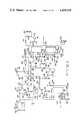
- FIG. 1is a schematic representation of a brushless DC motor and control arrangement for use with a refrigeration system in practicing the present invention in one preferred form;
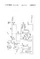
- FIG. 2is an electrical schematic diagram showing details of an evaporator fan control circuit illustrated in FIG. 1;
- FIGS. 3, 4, and 5are electrical schematic diagrams showing details of a regulating circuit illustrated in FIG. 1;
- FIGS. 6 and 7are electrical schematic diagrams showing details of a commutation circuit illustrated in FIG. 1;
- FIG. 8is an electrical schematic diagram showing details of a recovery circuit illustrated in FIG. 1;
- FIG. 9is a diagrammatic front elevational view of a stationary armature for the three stage brushless DC motor of FIG. 1, diagrammatically illustrating winding details for the three stages of the motor;
- FIG. 10is a front elevational view of a permanent magnet rotor for the brushless DC motor of FIG. 1;
- FIG. 11is a graph of speed versus torque for different operating voltages of a particular brushless DC motor constructed in accordance with the teachings of the present invention.
- FIG. 12is a graph of efficiency versus speed for different operating voltages of the particular brushless DC motor and control arrangement having the characteristics illustrated in FIG. 11;
- FIG. 13is a schematic diagram more particularly showing a refrigeration system of a type with which the brushless DC motor and control arrangement of FIG. 1 is particularly adapted for use.
- FIG. 1schematically illustrates a brushless DC motor and control arrangement particularly adapted for use with a refrigeration system such as, for example, a vehicular air conditioning system and which may be utilized in carrying out the present invention in one form.
- a three stage brushless DC motor 20having a winding stage 22, a winding stage 24, and a winding stage 26 is provided.
- Each of the winding stagesis connected at one end thereof to a power source, illustrated as alternator 28.
- An arrangementis provided for controlling operation of the brushless DC motor with such arrangement including a commutation circuit 30, a regulating circuit 32, and an evaporator fan control circuit 34.
- a typical refrigeration systemwhich could be controlled by the illustrated brushless DC motor and control arrangement, would be an automotive air conditioning system having a condenser, an evaporator, and a compressor.
- a schematic representation of such a systemis shown in FIG. 13.
- the three stage brushless DC motor 20includes a rotor 552 (FIG. 9) having constant magnetic polarity regions established thereon by permanent magnets.
- the rotorwould be coupled to a compressor for moving a refrigerant in a conventional manner for cooling a passenger compartment of an automobile.
- such a compressorwould move a refrigerant in a liquid form through a condenser for cooling the refrigerant with a condenser fan sometimes being provided to facilitate the cooling.
- the liquid refrigerantwould be moved from such a condenser through an expansion valve for converting the liquid refrigerant into a gaseous form at a lower pressure for subsequent feeding to an evaporator.
- An expansion valvewhich could be utilized with a refrigeration system being controlled by the illustrated brushless DC motor and control arrangement, would be an expansion valve, of a conventional type, which would vary refrigerant flow in accordance with compressor speed and which would be operative to sense and vary refrigerant flow in accordance with evaporator temperature and refrigerant pressure.
- Such an evaporatorwould be located in the passenger compartment of a vehicle for use in controlling the temperature therein.
- An evaporator fan unitwhich would include a motor such as fan motor 36 of FIG. 1, would be utilized to move air across an evaporator for cooling a passenger compartment of a vehicle.
- the brushless DC motor 20includes the winding stages 22, 24, and 26 with one end of each of the winding stages being connected to line 38 which is connected to a power source illustrated as alternator 28.
- the alternatorhas an output which is controllable over a predetermined voltage range such as, for example, from 33 volts to 82 volts to supply energization power to the winding stages.
- the output voltage, V Mof the alternator is varied by a regulating means illustrated as the regulating circuit 32.
- the regulating circuit 32controls the operating speed of the brushless DC motor by controlling the alternator output voltage so as to vary the energization level or degree of energization of the winding stages.
- the refrigerant flow rate and thus, the effective cooling of the systemis varied by varying the speed of the brushless DC motor because the motor speed determines the operating speed of a compressor connected thereto.
- the temperature, illustrated as T Cof a compartment being cooled, is sensed by the evaporator fan control circuit 34.
- the fan control circuitcompares the sensed compartment temperature with a desired compartment temperature to produce a speed control signal which is utilized to cause intermittent operation of a power switching means, illustrated as power transistor 40. Conduction of the power transistor causes a constant voltage, V B , to be supplied to the fan motor from a constant voltage power source 42 which may be, for example, a twelve volt DC battery.
- the average power being supplied to the fan motor 36is varied for varying the fan motor speed.
- the fan control circuitcauses an increase in the average power being applied to the fan motor; thus, the fan motor speed is increased for bringing the compartment temperature down to the desired temperature.
- the speed at which the fan motor is to be operatedis also indicative of the cooling demand within a compartment being cooled.
- An output demand signal, S Dwhich is indicative of the relative cooling demand, is produced by the fan control circuit by comparing the speed control signal of the circuit with a predetermined speed signal with the output demand signal, S D , being produced when the predetermined speed signal is exceeded.
- an evaporatoris maintained at a preselected control temperature by varying the speed of the brushless DC motor 20.
- the motorwould be connected to a compressor; thus, by varying the motor speed, the speed of a compressor is varied to vary the flow rate of refrigerant to an evaporator.
- the regulating circuit 32senses the temperature, T V , of a selected portion of an evaporator and compares this temperature with the preselected reference or control temperature.
- the regulating circuitcontrols the value of the output voltage, V M , of the alternator 28 in accordance with the difference between the measured evaporator temperature, T V , and the preselected reference temperature by intermittently operating a power switching means such as, for example, power transistor 172 so as to intermittently interrupt current flow to a field winding of the alternator.
- a power switching meanssuch as, for example, power transistor 172 so as to intermittently interrupt current flow to a field winding of the alternator.
- the preselected reference temperature of an evaporatoris changed in accordance with the relative cooling demand of a compartment being cooled by the system.
- the regulating circuit 32changes the preselected reference temperature in response to the output demand signal, S D , of the evaporator fan control circuit 34.
- the regulating circuit 32may be controlling the brushless DC motor 20 so as to maintain an evaporator at a first preselected reference temperature, for example, 45° F. (7.2° C.). If the compartment temperature, T C , is at a value so as to demand that the evaporator fan control circuit control the speed of the fan motor at a relatively high speed such as, for example, 3/4 of maximum fan motor speed, the fan control circuit will generate the output demand signal S D , indicating a relatively high compartment cooling demand. The regulating circuit responds to the demand signal by changing its reference temperature to a second preselected reference temperature such as, for example, 30° F. (-1.1 C.). The regulating circuit will then control the evaporator temperature at the second preselected reference temperature which will lower the temperature of air being moved across an evaporator by the evaporator fan motor.
- a first preselected reference temperaturefor example, 45° F. (7.2° C.).
- T Cthe compartment temperature
- the evaporator fan control circuitwill generate the output demand signal
- a decrease in demanded fan motor speed to a predetermined value, for example, 1/2 of full fan motor speedwould indicate a decrease in compartment cooling demand and cause the evaporator fan control circuit to terminate the output demand signal, S D .
- the regulating circuitwould respond to the termination of the demand signal by changing the evaporator reference temperature to the first preselected reference temperature.
- the speed of the brushless DC motor 20is varied by varying the output voltage, V M , of the alternator 28.
- the alternator voltageis selectively applied to the winding stages 22, 24, and 26 by selectively operating power switching means illustrated as power transistors 46, 48, and 50.
- the winding stagesare selectively energized and deenergized with the alternator output voltage in accordance with the relative position of the rotor 552 (FIG. 9) and the winding stages of the motor.
- the commutation circuit 30is responsive to the emf voltage produced in a selected unenergized winding stage for determining the relative position of the rotor and the winding stages.
- the commutation circuitcauses selective energization of the winding stages 22, 24, and 26 by selectively operating the power transistors 46, 48, and 50.
- a commutation circuitsuch as illustrated in FIGS. 37a and 37b of my co-pending application Ser. No. 802,484, which has been previously incorporated herein by reference, may be utilized to selectively energize and deenergize the winding stages 22, 24, and 26.
- a slightly modified version of that commutation circuitis preferred in this particular application. This preferred commutation circuit is illustrated in FIGS. 6 and 7 and will be discussed more fully hereinbelow.
- the preferred way of controlling a refrigeration systemincludes operating the brushless DC motor 20 at a predetermined minimum energization level to assure operation of a lubrication arrangement functioning to lubricate bearings of the motor.
- the regulating circuit 32includes a minimum energizing means for assuring a minimum voltage output of the alternator 28. It is also preferred to limit the maximum energization level of the brushless DC motor to protect windings and power circuitry of the motor.
- the regulating circuitis provided with a means for limiting energization of the windings by the alternator to a maximum predetermined value.
- the regulating circuitis responsive to a signal Sp from the commutating circuit 30 which is representative of the speed of the brushless DC motor.
- the regulating circuitcompares the speed of the motor with a predetermined low speed value such as, for example, 2500 rpm, and inhibits motor operation if such speed is less than the predetermined value by interrupting alternator output power and by inhibiting operation of the commutation circuit 30 by way of an output signal S f .
- motor operationis stopped by either inhibiting the alternator output voltage or by inhibiting the commutation circuit; however, it is preferred to inhibit both the alternator and commutation circuit.
- the regulating circuitalso includes a means to cause an automatic restart of the motor after a predetermined period of time has elapsed following a low speed shutdown.
- the maximum speed of the motoris further limited to a maximum predetermined speed value by the regulator circuit in that the regulator circuit compares the speed of the brushless DC motor with the maximum predetermined speed value such as, for example, 8000 rpm, and intermittently inhibits the alternator field so as to control the output voltage V M of the alternator in order to assure that the motor speed does not exceed the maximum predetermined value.
- the preferred way of operating a refrigeration systemalso includes limiting evaporator temperature to a predetermined low temperature value.
- the regulating circuit 32compares the temperature, T V , of a selected portion of the evaporator with a predetermined low temperature value such as, for example, 25° F. (-3.9° C.), and inhibits operation of the alternator 28 and operation of the commutation circuit 30 if the evaporator temperature is less than the predetermined low temperature reference value which is indicative of an evaporator freeze-up condition.
- An energy recovery circuitis employed in recovering the stored energy.
- stored energy from the winding stages 22, 24, and 26is fed to capacitor 54 by way of diodes 56.
- logic and driver circuit 58which includes a voltage dividing circuit arrangement, operates to cause conduction of the transistor 60.
- Conduction of the transistorcauses the stored energy to be transferred from the capacitor 54 to capacitor 62 by way of the transistor and inductor 64 for addition to the alternator output voltage, V M .
- the inductorfunctions to limit and smooth the current during the energy transfer so as to protect the transistor, and diode 66 provides a path for stored current in the inductor when the transistor is not conducting.
- FIG. 2illustrates details of the evaporator fan control circuit 34 of FIG. 1.
- the fan control circuit 34controls the speed of the evaporator fan motor 36 (FIG. 1) so as to vary air flow across an evaporator of a refrigeration or air conditioning system for controlling the temperature within a compartment.
- the temperature within a compartment being cooledis sensed by a negative temperature coefficient resistor or thermistor 68 connected to a regulated voltage source, V R , for generating a signal representative of a compartment temperature.
- This temperature representative signalis fed through conditioning amplifier 70 and input resistor 72 to a differential amplifier 74.
- the amplifier 74compares the signal representative of the temperature within a compartment with a predetermined reference voltage on line 76 which is indicative of a desired compartment temperature.
- the predetermined reference voltage on the line 76is developed by a voltage dividing network comprising resistors 78, 80, and 82 with a filtering capacitor 84 also being provided.
- the desired reference temperatureis adjusted by adjusting the variable resistor 80.
- the amplifier 74produces an output speed control signal on line 86 which is supplied to switching regulator 88.
- the switching regulatorwhich is supplied with voltage, V B , from constant voltage source 42 (FIG. 1), produces output pulse signals on line 90 which vary in duration according to the magnitude of the input speed control signal on the line 86.
- Adjustable resistor 92connected to the switching regulator, provides an adjustment of the minimum switching speed for the regulator and thus, is utilized to set a minimum speed for the fan motor 36 (FIG. 1).
- the output pulse signals on line 90are fed through input resistor 94 to the base of the power transistor 40.
- the power transistorhas its collector connected to the constant voltage source 42 (FIG. 1) and its emitter connected to the fan motor 36 (depicted in FIG. 2 as a winding) having diode 96 connected thereacrosss. Conduction of the power transistor causes the constant voltage, V B , to be applied to the fan motor.
- the intermittent switching of the power transistor in accordance with the pulse signals on line 90causes an average power to be supplied to the fan motor.
- the average power and thus the speed of the motorvaries as the pulse signals vary in accordance with deviation of compartment temperature from the desired compartment temperature as determined by the differential amplifier 74.
- the fan speedincreases to move more air across an evaporator to produce greater cooling as the compartment temperature rises above the desired temperature.
- the fan control circuit 34further includes a means for determining the relative cooling demand of a compartment being cooled.
- the demand meansis illustrated as comparator 98 which has the speed control signal of line 86 fed to one input thereof by way of resistor 100.
- the speed control signaldetermines the speed of the evaporator fan motor 36 and the speed is increased as more cooling is demanded in a compartment.
- the speed control signal of line 86is indicative of fan motor speed and indicative of compartment cooling demand.
- the comparator 98compares the speed control signal with a predetermined reference voltage on line 102 which is indicative of a predetermined fan speed or cooling demand.
- the predetermined reference voltageis developed on the line 102 by way of voltage dividing resistors 104 and 106 which are connected to the regulated voltage, V R .
- the regulated voltageis also supplied to the comparator at line 108 and to load resistor 110 which is connected to the comparator output line 112 for setting the level of the signal thereon.
- a high level logic signalis produced on the line 112 at the comparator output until the input control speed signal is greater than the predetermined reference voltage at line 102, for example, a voltage indicative of 3/4 full fan speed of line 102.
- the comparatoroperates to reduce the logic signal (S D in FIG. 1) to a low level thereby indicating a relatively high compartment cooling demand.
- Feedback resistor 114provides a deadband or hysteresis resetting effect for the compartor, i.e., the speed control signal must decrease to a lower predetermined voltage, for example, a voltage indicative of 1/2 full fan speed before the comparator will reset.
- FIGS. 3-5illustrate details of the regulating circuit 32 of FIG. 1.
- a negative temperature coefficient resistor or thermistor 116is connected to regulated voltage supply V R by way of resistor 118 to produce a signal on line 120, which is representative of the temperature of a selected portion of an evaporator.
- This representative signalis supplied through an amplifier 122 to either of two differential amplifiers, 124 or 126 having identical input and gain resistors, 128 and 130, respectively.
- Each of the amplifiers 124 and 126have an identical voltage dividing network connected thereto comprising resistors 132, 134, and 136 with resistors 132 being connected to regulated voltage, V R .
- the resistors 134are adjusted to different resistance values so as to provide different predetermined voltages on lines 138 and 140 at the input of the amplifiers 124 and 126, respectively.
- the predetermined voltage on line 138is indicative of a first preselected reference temperature such as, for example, 30° F. (-1.1° C.)
- the predetermined voltage on line 140is indicative of another preselected reference temperature such as, for example, 45° F. (7.2° C.).
- the position of switch contacts 142 and 144which are connected in series with the outputs of the amplifiers 124 and 126, respectively, and which have diodes 148 and 150, respectively, connected thereto, determine which amplifier is operative, and thus, determine the reference temperature at which an evaporator is to be controlled.
- the switchesare operated in response to the logic signal on line 112 from the fan control circuit with the logic signal being fed through NAND gate 146, connected as an inverter, for operating contact 142.
- a signalis prduced on line 152 by either amplifier 124 or 126 which is representative of the deviation of the evaporator temperature from a predetermied selected reference temperature, This representative signal is fed through manual-automatic switch contact 154, resistor 156, amplifier 158 and resistor 160 to one input of comparator 162.
- the other input to the comparator 162is connected to line 38 at the output of the alternator 28 (FIG. 1) by way of voltage dividing resistors 164, 166, and 167 so as to produce an input signal representative of the output voltage, V M , of the alternator.
- the comparator 162compares the signal at its one input, which is representative of evaporator temperature deviation from a preselected reference temperature, with the signal representative of the alternator output voltage, and interrupts current flow through a field coil 168 of the alternator when the temperature representative signal is less than signal representative of the alternator voltage.
- Current flow throught the alternator field coil 168is provided when transistors 170 and 172 are made conductive by feeding a signal to the base of the transistor 170 by way of resistors 174 and 176; however, operation of the comparator 162 interrupts current flow through the field coil by establishing an alternate signal path from the resistor 174 to ground therby making the transistors 170 and 172 non-conductive.
- Diode 178 connected across the field coilprovides an alternate path for current in the coil when the transistors are non-conductive.
- the alternator output voltage, V Mand thus the speed of the brushless DC motor 20 (FIG. 1) is controlled to maintain an evaporator temperature at the predetermined reference temperature.
- the regulator circuitis also provided with a means of assuring a minimum alternator output voltage which in turn assures that the winding stages 22, 24, and 26 (FIG. 1) of the brushless DC motor will be energized at a predetermined minimum voltage level.
- this predetermined minimum energization levelis provided by supplying a predetermined voltage level to line 152 by way of resistor 180 and diode 182 with the resistor being connected to regulated voltage, V R .
- This predetermined voltage level, on line 152may be varied by adjusting the resistor 180 which in turn adjusts the minimum energization level and speed of the motor.
- the regulating circuitis also provided with a means to limit the maximum energization level of the winding stages 22, 24, and 26 of the brushless DC motor.
- this limiting meanscomprises a clamping circuit including diode 184 and amplifier 186 having an adjustable input voltage provided by resistor 188 connected to the regulated voltage supply, V R .
- the clamping voltage, and thus, the maximum energization level for the winding stages,may be varied by adjusting the variable resistor 188.
- the regulating circuitis also provided with a means to limit current in the brushless DC motor.
- a comparator 190is provided to limit the motor current by interrrupting current to the alternator field coil 168. By interrupting the field coil current, the comparator controls the alternator output voltage so as to limit motor current to a maximum predetermined value such as, for example, 60 amperes peak current.
- the current in the winding stagesis sensed by the comparator 190 by connecting wire leads 192 and 194 across a shunt resistor 196 (FIG. 1).
- the shunt resistorhas a low resistance value such as, for example, 0.003 of an ohm and is connected in series with the winding stages 22, 24, and 26 as illustrated in FIG. 1.
- a voltage dividing arrangementcomprising resistors 196, 198, 200, 202, and 204 is provided at the inputs of the comparator with resistors 202 and 204 being connected to a regulated volage, V R .
- V Ra regulated volage
- the regulating circuitis also provided with a means for allowing either manual or automatic operation of the ciruit.
- a signalis supplied on line 212 for causing closure of the switch 154 which is connected in series with resistor 156.
- the switch 154When the switch 154 is closed, the evaporator temperature, as sensed by the thermistor 116, will be automatically controlled at a predetermined reference temperature as set by either amplifier 124 or amplifier 126.
- the contact 154is opened and contact 214 is closed by a signal from NOR gate 216. With the contact 214 closed, the temperature of an evaporator can be manually controlled by way of adjustable resistor 218 which is connected to the regulated voltage, V R .
- the regulating circuitis also provided with a means to inhibit operation of the brushless DC motor when the evaporator temperature, as sensed by the thermistor 116, is less than a predetermined low temperature value.
- the voltage at the output of the amplifier 122is representative of the temperature at a selected portion of an evaporator.
- This representative signalis supplied to a comparator 220 by way of resistor 222 where it is compared with a predetermined reference voltage on line 124, which is representative of a predetermined low temperature value such as, for example, 25° F. (-3.9° C.).
- the predetermined reference voltageis provided by a voltage divider circuit comprising resistor 226, which is connected to the regulated voltage, V R , and resistors 228, 230, and 232.
- the predetermined voltagemay be adjusted by adjusting the variable resistor 228.
- a high level logic signalis normally produced on line 234 at the comparator output by the regulated voltage V R and load resistor 236; however, when the evaporator temperature drops to the predetermined low temperature value, the comparator 220 operates to cause the logic signal on line 234 to go to a low level.
- Feedback resistors 238 and 240provide a resetting of the comparator at a voltage different than the predetermined reference voltage such as, for example, a voltage indicative of 35° F. (1.7° C.), thus, the feedback resistors provide an operating deadband for the comparator which can be varied by adjusting the resistor 240.
- the operation of these logic elementscauses a high level logic signal to be produced at line 248 for inhibiting operation of the alternator 28 (FIG. 1).
- the alternatoris inhibited by interrupting current flow to the alternator field coil 168. This current interruption is accomplished by feeding the high level logic signal of line 248 through resistor 250 to the base of transistor 252 for causing conduction thereof. Conduction of the transistor 252 establishes a current path to ground thereby making transistors 170 and 172 non-conductive, and thus, interrupting current flow in the alternator field coil 168.
- a first delay circuitcomprising diode 260, resistors 262 and 264 and capacitor 266, is connected between the NOR elements 244 and 254.
- a second time delay circuitcomprising diode 268, resistors 270 and 272 and capacitor 274, is connected between the NOR elements 244 and 246.
- the two time delay circuitshave identical resistance and capacitance values with the resistors 262 and 270 having relatively low resistance values, for example, 10 k ohms, and with resistors 264 and 272 having relatively high resistance values, for example 1 megohm.
- FIG. 4also illustrates a logic arrangement for manually disabling or inhibiting further operation of the alternator and the commutation circuit.
- a high level logic signalis applied on line 276.
- This high level logic signalis fed through resistor 278 to the base of NPN transistor 280 having resitor 282 connected between the base and emitter thereof, and having load resistor 284 connected to the collector.
- the high level logic signalcauses conduction of the transistor to produce a low level signal at the collector.
- This low level signalis inverted by NAND element 286 to produce a high level signal on line 288 at the input of the NAND element 242.
- the high level signal, at the line 276,is removed which causes a low level signal to be produced at the line 288 of the NAND element 242.
- a low level signal at the input to the NAND element 242causes an inhibiting low level signal to be produced on the line 258 and also causes an inhibiting high level signal on the line 248 in the same manner as the previously discussed low temperature signal of the line 234.
- FIG. 4also illustrates logic circuit arrangements for inhibiting operation of the alternator and the commutation circuit during a low motor speed condition or during a high temperature condition.
- a low logic signalis present at input line 290 of NAND element 292. Derivation of the signal on line 290 will be discussed later in this application in describing FIG. 5.
- a predetermined low speed limitfor example, 2500 revolutions per minute (rpm)
- rpmrevolutions per minute
- the signal level at the other output, i.e., line 294 of the NAND element 292is normally high; thus, a low speed signal on line 290 will cause operation of the NAND element to produce a low level logic signal at NAND element 296.
- the low level signalcauses operation of the NAND element 296 thereby producing a high level logic signal on line 298 at the input of the NOR element 244 which causes operation of the NOR element.
- operation of the NOR element 244i.e., causing its output to go to a low level, produces alternator and commutation circuit inhibit signals on lines 248 and 258, respectively.
- a circuit arrangementis provided, as illustrated in FIG. 4, for automatically restarting the brushless DC motor after a predetermined time has elasped following operation of the low speed inhibiting circuitry described hereinabove.
- a high level logic signalis produced on the line 298 when the motor speed is below a predetermined low speed value.
- the high level signal on the line 298is fed to the input of NAND element 300.
- the other input to the NAND element 300is also at a high signal level provided no high temperature limit has been exceeded as will be later discussed.
- a low level signalis produced at the output of the NAND element 300 causing a low signal level at line 302 of a one-shot timer arrangement comprising NAND elements 304 and 306, capacitor 308, diode 310 and resistors 312, 314, and 316.
- a low level signal on line 302causes the NAND element 304 to produce a high level output to line 318 which in turn causes the NAND element 306 to produce a low level output signal thereby dropping the charge or voltage across the capacitor 308.
- the capacitor voltageis lowered, a low signal level results at line 320 or the other input of the NAND element 304.
- the signal at the line 302goes back to a high level as capacitor 322 is recharged by the regulated voltage, V R , by way of resistor 324.
- a longer time delayfor example, two minutes, is provided for recharging the capacitor 308 by way of the resistor 314.
- the capacitor 308is recharged to produce a high level logic signal on the line 320.
- This high level signal on line 320causes operation of the NAND element 304 which in turn causes a low level signal to be produced on line 318.
- a drop in signal level on line 318causes operation of NAND element 326 which is connected to line 318 by way of capacitor 328.
- the capacitor 328is recharged by the regulated voltage, V R , which is connected to the capacitor by way of resistor 330.
- V Rregulated voltage
- An identical arrangementis provided at the other input of the NAND element 326 by resistor 332 and capacitor 334.
- a high level signalis produced at its output for triggering another one-shot timer arrangement comprising NOR elements 336 and 338, capacitor 340, diode 342, and resistors 344, 346, and 348.
- Operation of the one shot timercauses the signal level on line 294 to drop, thereby operating the NAND element 292 to produce a high level signal at the output thereof for overriding the low speed signal on the line 290.
- a low level signalis produced at the input of the NOR element 244, i.e., at line 298, thereby enabling restart of the brushless DC motor.
- a low speed inhibit signal on the line 290is overridden by operation of the previously described one-shot NOR timer arrangement for originally starting the system as well as following a time delayed restart.
- the speed of the brushless DC motormust reach a predetermined low speed value within a predetermined period of time such as, for example, six seconds, or else a high level signal will once again be produced on the line 294 to cause operation of the commutation circuit and alternator to be inhibited.
- the predetermined time delayis provided by the resistor 346 and the capacitor 340 in the illustrated circuit.
- the regulating circuitis also provided with a means for inhibiting operation of the alternator and the commutation circuit when a temperature, at a preselected sensing location in the system, exceeds a predetermined high temperature limit.
- a temperatureis sensed at a heat sink provided for the motor power transistors; however, the temperature at other locations such as, for example, a compressor case could be monitored for high limit.
- a high temperature limitis provided by comparator 350 having a resistor 352 and filtering capacitor 354 connected to its input line 356.
- the comparatoris also provided with an output load resistor 358 for setting the level of its output logic signal.
- a positive temperature coefficient resistor 358is also connected to the input line 356 for sensing the temperature of the power transistor heat sink.
- the comparatorcompares the input signal at the line 358, which is representative of heat sink temperature, with a predetermined reference voltage which is indicative of a predetermined high temperature value.
- This predetermined reference voltageis establisehd on line 362 at the other input of the comparator by the regulated voltage, V R , and voltage dividing resistors 364 and 366.
- the positive temperature coefficient resistor (PTCR) 360senses a high temperature such as, for example, 85° C.
- the predetermined reference voltage at the line 362is exceeded causing operation of the comparator.
- Operation of the comparatorcauses a logic signal, at output line 368 thereof, to drop to a low level.
- This low level signalis transmitted to an input of the NAND element 296 for causing operation of the NAND element.
- Operation of the NAND element 296causes operation of the NOR element 244 to produce commutation circuit and alternator inhibit signals as previously discussed.
- the low level signal of the line 368is also fed to an input of the NAND element 300 to prevent automatic time delayed restart of the alternator and commutation circuit until the high temperature condition has ceased.
- the regulating circuitis further provided with a means for detecting that the brushless DC motor has reached a high speed limit value and for controlling the motor once the high speed value limit has been reached so as to prevent damage to the motor at its power circuitry.
- An excessive high speedmay be demanded when, for example, a refrigeration system has lost its charge and/or a temperature sensor has failed.
- a pulse signalis transmitted on line 370 from the commutating circuit (see FIG. 6) each time a winding stage of the brushless DC motor is energized; thus, this signal is indicative of the relative speed of the motor.
- the pulse signalsare fed through a low pass filter, comprising resistors 372 and 374 and capacitors 376 and 378, to amplifier 380 for producing a signal at line 382 which is representative of an average motor speed.
- This average speed signal on line 382is fed to comparator 384 by way of resistor 386.
- the comparator 384compares this average speed input signal with a predetermined reference voltage on line 388 which is produced by way of the regulated voltage, V R , and voltage dividing resistors 390 and 392. This predetermined reference voltage may be varied by adjustment of the adjustable resistor 390.
- the comparatorWhen the average speed signal exceeds the predetermined reference voltage which is indicative of a predetermined maximum speed such as, for example, 8,000 revolutions per minute (rpm), the comparator operates to ground its output line 210. As illustrated in FIG. 3, this output line 210 is connected to the switching transistors 170 and 172 which allow current flow through the alternator field coil 168 when in their conductive state. However, grounding of the line 210 switches the transistors to a non-conductive state thereby interrupting current flow through the field coil of the alternator. Thus, operation of the comparator 384 controls the output voltage of the alternator so as to prevent the exceeding of the maximum predetermined motor speed.
- a predetermined maximum speedsuch as, for example, 8,000 revolutions per minute (rpm)
- the averge speed signal, produced at the line 382 of FIG. 5is also fed, by way of resistor 394, to a comparator 396.
- This average speed signalis compared by the comparator with a predetermined reference voltage on line 398 which is indicative of a predetermined low motor speed value, such as, for example, 2500 rpm.
- the predetermined reference voltageis produced at the line 398 by way of regulated voltage, V R , adjustable resistor 400 and resistor 402.
- V Rregulated voltage
- FIGS. 6 and 7illustrate details of the commutating circuit 30 of FIG. 1.
- this commutating circuitis substantially similar to the commutating circuit illustrated in FIGS. 37A and 37B of my co-pending application Ser. No. 802,484, the disclosure of which has been previously incorporated herein by reference.
- the arrangement disclosed hereinapplies a higher voltage to motor winding stages than the previously disclosed arrangements; thus, some modifications were made from the previously disclosed arrangement in order to accommodate for differences in cost and availability of circuit components.
- the commutating circuit 30, as shown in FIG. 1 and FIGS. 6 and 7,detects the emf voltage generated in a selected unenergized winding stage, processes the detected emf signal so as to determine the relative position of the rotor and winding stages, and produces a simulated relative position output signal for selectively energizing and deenergizing the winding stages 22, 24, and 26 in accordance with the relative position of the rotor and windings.
- a detector circuit 406shown within dotted lines in FIG. 6, is connected to each of the winding stages to selectively sense the emf voltage of a particular winding stage such as, for example, the next winding stage to be energized.
- the emf voltage of the particular winding stage being sensedis determined by subtracting the alternator output voltage, V M , and the voltage at the opposite end of the particular winding stage, for example, V A , V B , V C .
- the emf voltageis then fed to a position determining circuit 408 wherein the emf voltage is conditioned and processed to produce a simulated relative position output signal which is indicative of the relative position of the rotor and windings of the motor.
- such simulated relative output signalis in the form of a logic signal at the output of the position determining circuit.
- a circuit means 410processes the incoming simulated position signal through an indexing or sequence arrangement to produce an output signal for triggering energization of a particular winding stage.
- the circuit meansalso causes deenergization of the previously energized winding stage and selection of another deenergized winding stage to be sensed by the detector circuit. This operational procedure occurs continuously during motor operation with the emf voltage of each winding stage being selectively detected and processed to selectively energize and deenergize each of the winding stages.
- the detector circuit 406 of FIG. 6senses the output voltage, V M , of the alternator 28 (FIG. 1). This voltage signal is reduced by a voltage divider including resistors 412 and 414, and fed to input line 416 of differential amplifier 418 by way of resistor 420.
- the voltage signals at the opposite ends of each of the winding stagesthat is V A , V B , and V C , are selectively fed to line 422 at the other input of the differential amplifier through respective resistors 424, respective voltage dividers including resistors 426 and 428, and switching contacts 430, 432, and 434, respectively. Only the switching contact for the particular unenergized winding stage in which emf voltage is being detected will be closed.
- a predetermined minimum voltage such as, for example, 0.7 voltsis provided by a power supply comprising diode 336 and capacitors 338 and 340 with power being supplied to the capacitors by the regulated voltage, V R , by way of resistor 342.
- V Rthe regulated voltage
- the differential amplifier 418also has resistor 448, feedback resistor 450 and adjustable resistor 452 connected thereto with the adjustable resistor 452 providing an amplifier bias.
- the emf voltage output signal of the differential amplifier 418is supplied to the operational amplifier 446 by way of resistor 454 and switch contact 456.
- the operational amplifierwith capacitor 458 and zener diode 460 connected thereacross, operates to integrate positive emf voltage from the zero crossing point of the emf voltage signal.
- the zener diodefunctions to prevent integration of negative emf voltage so that integration starts at the zero crossing of the emf voltage, and the diode also determines the reset reference voltage of the capacitor 458 prior to beginning each integration.
- comparator 462which is connected to the operational amplifier output by way of resistor 464, is operated to produce high level logic signal at the output of the comparator.
- the predetermined reference level at which the comparator is operatedis determined by a voltage divider comprising resistor 466 and adjustable resistor 468.
- the adjustable resistoris connected to the regulated voltage, V R , for producing a predetermined reference voltage at input line 470 of the comparator.
- the comparatorhaving load resistor 472 and feedback resistor 474 connected thereto, provides a Schmitt trigger function so as to produce an output pulse when the integrated voltage level falls below the predetermined reference voltage.
- the rotor 552illustrated in FIG. 10, is provided with arcuate permanent magnet segments 586 disposed on a low reluctance core 584 so as to establish constant magnetic polar regions with North-South polarizations.
- the integrated emf voltage level, at which the comparator 462 of FIG. 6 operates,is indicative of a predetermined relative position of the rotor and windings of the brushless DC motor.
- the comparator output signalindicates that this predetermined position has been reached, and thus, the signal is utilized to commutate the winding stages of the motor, as will be discussed more fully hereinbelow.
- this predetermined number of volt-seconds or commutation levelis selected to provide an advance timing angle or a predetermined amount of advancement.
- a zero advancewould exist if a winding stage was turned on when the magnetic center of a rotor established polar region was moving theretoward and at the instant that the magnetic center of the region was 135 electrical degrees from alignment with an axis of a magnetic pole established by energizing the winding stage.
- a zero advancement of commutationis a theoretical optimum; however, switching the winding stage before this theoretical optimum, i.e., providing advancement of commutation, is preferred in order to allow for current build-up in the winding stage to achieve the maximum possible torque throughout the "on" time of the winding stage.
- the preferred amount of advancementis associated with the L/R time constant of a winding stage; however, typically the prefered advancement of commutation is from about five electrical degrees to about 30 electrical degrees.
- the advancement of commutation anglemay be adjusted by adjusting the variable resistor 468 and thereby changing the operating voltage of the comparator 462.
- the high logic level output signal of the comparator 462which indicates that a predetermined relative position has been reached, is fed through an RC filter, comprising capacitor 476 and resistor 478, to a one-shot multivibrator comprising NOR elements 480 and 482, capacitor 484 and resistor 486.
- This input signalcauses the multivibrator to produce a high logic level output signal at the line 370 which is utilized by the circuit means 410 to cause winding stage commutation.
- the multivibrator output signalis also fed to the previously discussed high speed and low speed circuitry (FIG. 5) of the regulating circuit.
- the multivibrator output signal on the line 370 and the output signal of the comparator 462are fed to a logic arrangement comprising NOR elements 488 and 490 for closing reset switch 492, having resistor 494 connected thereto, and for opening the contact 456. Operation of the NOR elements and switches resets the integrator by recharging the capacitor 458 back to a predetermined reference level.
- the circuit means 410receives the high logic level output signal of the multivibrator on the line 370, which is indicative of a predetermined relative position, and utilizes this signal to: select the next winding stage to be energized; cause deenergization of the presently energized winding stage; and to select another unenergized winding stage for detection of emf voltage therein by the detector circuit 406.
- the multivibrator output signalis supplied to a flip-flop arrangement comprising flip-flops 496 and 498 to provide signals Q1 and Q2 along with their complements (Q1, Q2) to be logically combined by a decoder comprising three NAND elements 500.
- the decoding of the Q1 and Q2 signals and their complementscauses a low level logic signal to be produced at the output of one of the NAND elements 500 and high logic level signals at the outputs of the remaining two NAND elements 500.
- each of these circuitscomprise an RC filter comprising resistor 502 and capacitor 504, an invertor 506, a NAND element 508, an invertor 510, a resistor 512, switching transistors 514 and 516, and current limiting resistors 518 and 520.
- the circuitfunctions to cause selective energization and de-energization of the winding stages 22, 24, and 26 by switching parallel connected power transistors 46a and 46b, 48a and 48b, and 50a and 50b, respectively, which are provided for switching the alternator output voltage, V M .
- the signalis inverted by an invertor 506.
- This inverted signal(Sa, Sb, or Sc) causes a closure of one of the switch contacts (430, 432, or 434) for selecting another unenergized winding stage for emf voltage sensing by the detecting circuit 406 of FIG. 6.
- This inverted signalalso causes operation of a respective NAND element 508, invertor 510 and switching transistors 514 and 516 to cause a switching of the appropriate power transistors for energization of another winding stage.
- the NAND elements 508have another input signal supplied thereto by way of line 258 to inhibit energization of any of the winding stages when so directed by the regulating circuit as previously discussed in reference to FIG. 4.
- the circuit means 410continuously indexes with each signal from the position determining 408 to cause energization of another winding stage, de-energization of the previously energized winding stage and selection of another unenergized winding stage for emf sensing by the detecting circuit 406.
- Resetting of the flip-flops 496 and 498 for providing this continuous indexing or sequencingis provided by NOR element 522 whose output signal is filtered by way of resistor 524 and capacitor 526.
- This multivibrator output signalcauses operation of another one-shot multivibrator comprising NOR elements 528 and 530, capacitor 532, and resistor 534. Operation of this multivibrator produces a reset signal on line 436 which is fed to each of the flip-flops 496 and 498.
- the back emf voltages sensed by the detetor circuitmay be zero and thus, voltage-time integration in the operational amplifier 446 might not take place except for the presence of a means for adding starting which causes a characteristic signal, which is indicative of low motor speed emf voltage, to be produced.
- this characteristic signalis produced by adjusting the bias resistor 352 so as to cause a low speed characteristic signal to be produced at the output of the differential amplifier 418; thus, continuous cycling of the integrating amplifier 446 and previously described reset circuitry is provided to assure starting of the brushless DC motor.
- FIG. 6also illustrates a regulated voltage source for producing the regulated voltage, V R , for use as a voltage source to the logic packages, operational amplifiers and circuitry illustrated herein.
- the direct current source voltage, V Bis fed through a regulating arrangement comprising emitter follower transistor 538, zener diode 540, resistors 542 and 544, and noise filtering capacitors 546 and 548 to produce the regulated voltage, V R , which may be, for example, 7.6 volts.
- a recovery circuit 52is provided for recovering energy stored in the winding stages upon their de-energization. This stored energy is fed from the winding stages through the diodes 56 (FIG. 7) along line 650 to capacitor 54 of the recovery circuit illustrated in FIG. 8. When the voltage, V O , across the capacitor reaches a predetermined level, the transistor 60 is made conductive to transfer the stored energy to the capacitor 62 for addition to the alternator voltage, V M .
- a comparator 652For triggering the transistor 60 to effect energy transfer, a comparator 652 is provided for comparing a signal indicative of the capacitor voltage, V O , with a signal indicative of the alternator voltage, V M , and for producing an output signal when the ratio of the capacitor voltage and the alternator voltage exceeds a predetermined value such as, for example, when the capacitor voltage is twice the alternator voltage.
- a voltage dividing arrangementis provided at each input of the comparator for reducing the input voltages and for setting the operating point of the comparator. As shown, the capacitor voltage, V O , is reduced by voltage dividing resistors 654 and 656 and the alternator voltage, V M , is reduced by voltage dividing resistors 658 and 660.
- Load resistor 662which is connected to regulated voltage, V R , is provided for setting the level of the comparator output signal.
- the comparator 652When the capacitor voltage reaches a predetermined level such as, for example, twice the alternator voltage, the comparator 652 produces an output signal for making transistor 664 condiuctive and thereby triggering conduction of the transistor 60.
- the conduction of the transistor 60causes transfer of the stored energy from the capacitor 54 to the capacitor 62 by way of the inductor 64 and shunt resistor 666 for addition of the stored energy to the alternator output voltage, V M .
- a current limiting arrangementwhich includes comparator 668 and transistor 670, for interrupting the energy transfer by the transistor 60 when a predetermined current value is exceeded.
- a reference voltage indicative of the predetermined current limit valueis developed at line 672 at one input of the comparator by a reference voltage network comprising resistors 674, 676, 678, 680 and zener diode 682.
- the reference voltagemay be varied by adjusting the adjustable resistor 676.
- the networkis connected to one side of the shunt resistor 666 and has the voltage, V O , across the capacitor 54 supplied thereto.
- the predetermined voltage developed at the input line 672is compared with a signal indicative of the voltage at the opposite side of the shunt resistor which is supplied to the other input of the comparator by way of resistor 684.
- the comparator 668When the current through the shunt resistor 666 exceeds a predetermined value, the comparator 668 operates to produce an output signal which is supplied through resistor 686 to the base of transistor 688 to cause conduction thereof.
- the collector of the transistor 688is connected to the base of transistor 670 by way of resistor 690; thus, conduction of the transistor 688 triggers conduction of the transistor 670 so that the signal being supplied from the comparator 662 is diverted to ground. Therefore, the transistor 664 is made nonconductive to thereby terminate conduction of the transistor 60 and thus, interrupt energy transfer during the high current condition.
- FIGS. 9 and 10illustrate details of a stationary armature 550 and the rotor 552, respectively, of the brushless DC motor.
- the diagrammatically illustrated winding arrangement of FIG. 9is substantially identical to the three stage, four pole armature arrangement illustrated in FIG. 29 of my co-pending application Ser. No. 802,484.
- the stationary armature 550includes a magnetic core 554 having a longitudinal axis (extending into the page) and twenty-four axially extending slots opening into an axially extending bore 556.
- the armaturefurther includes the three stage windings 22, 24, and 26 with each winding stage comprising four coils of concentric winding turns having side turns thereof disposed in the slots of the core to establish four magnetic poles when energized.
- the illustrated winding stage 24has four coils each having a predetermined number of conductor turns with the first coil being disposed in slots 558 and 560, the second coil being disposed in slots 562 and 564, the third coil being disposed in slots 566 and 568, and the fourth coil being disposed in slots 570 and 572.
- the first coilbeing disposed in slots 558 and 560
- the second coilbeing disposed in slots 562 and 564
- the third coilbeing disposed in slots 566 and 568
- the fourth coilbeing disposed in slots 570 and 572.
- the coilsmay be wound consecutively or wound separately and then disposed and interconnected so as to produce current flow as indicated ("X" indicating current flow into the page and ".” indicating current flow out of the page).
- the side turnsi.e., the portions of the conductor turns disposed within the slots, of the coils for winding stage 24 create four winding sets 574, 576, 578 and 580.
- the winding set 574is disposed in the slots 560 and 562; the winding set 576 is disposed in the slots 564 and 566; the winding set 578 is disposed in the slots 568 and 570; and the winding set 580 is disposed in the slots 572 and 558.
- the coils of the winding stage 24have been wound and disposed in the armature slots so that the conductor portions of each winding set will conduct current in the same axial direction as indicated, along the axial length of the core when the winding stage 24 is energized; thus, creating four magnetic poles or two pairs of magnetic poles, N b , S b as shown.
- the winding stages 22 and 26 of FIG. 9are formed in the same manner as described above for winding stage 24, with each having four winding sets with conductor portions conducting current in the same axial direction along the core when energized.
- the three stage, four pole armature winding arrangement of FIG. 9has a winding "spread" of 30 mechanical degrees or 60 electrical degrees.
- the "spread”is the angular expanse of adjacent core slots that carry the conductors of a given winding stage which instantaneously conduct current in the same axial direction along the axial length of the core.
- a set of winding stage 24occupies two adjacent slots and all the conductors within that set carry current in the same axial direction along the axial length of the core; thus, the spread is the angular expanse of the two slots occupied by the set which is 60 electrical degrees or 30 mechanical degrees.
- the core 554 of the stationary armature 550was provided with an outer diameter of 3.982 inches and with the bore 556 being 1.922 inches.
- Each of the 24 slotswas provided with a 0.094 inch opening into the bore.
- the corewas provided with an axial or longitudinal length of 1.75 inches.
- Each of the coilswere formed with 15 turns of single stranded aluminum wire having a 0.0718 inch diameter.
- FIG. 10illustrates the rotor 552 of the brushless DC motor.
- the rotoris provided with a bore 582 therethrough for mounting on a not shown rotor shaft with such shaft being rotatably supported by a conventional not shown bearing means within any not shown housing.
- the rotoris mounted within the bore 556 of the magnetic core 554 (FIG. 9) for rotation about the longitudinal axis of the stationary armature core.
- the rotor 552comprises a magnetic steel core 584 having magnet segments 586 disposed on the periphery of the rotor core for producing constant magnetic polar regions which may span, for example, 75 degrees as illustrated.
- the magnet segments 586were cobalt samarium magnets, but it will be understood that they could be ceramic or any other type of available magnet material. Each of the magnet segments was provided with an outer arcuate span of 371/2 degrees, a thickness of 0.290 inches as measured at the center of the arcuate span and an inner base length of 0.442 inches. Aluminum spacers 588 were provided between each of the pairs of magnet segments with the spacers having a 15 degree outer arcuate span, a thickness of 0.290 inches as measured at the center of the arcuate span and an inner base length of 0.179 inches.
- the magnet segments, aluminum spacers and rotor corewere two inches in axial length with the diameter of the illustrated rotor being 1.882 inches.
- the magnet segments and aluminum spacerswere adhesively bonded to the rotor core and then a fiberglasss tape was wrapped about the periphery of the rotory; however, any suitable means could be utilized to retain the magnet segments.
- FIGS. 11 and 12illustrate operating characteristics of a particular brushless DC motor constructed and utilized in accordance with the teachings of the present invention.
- FIG. 11is a graph of motor speed in revolutions per minute (rpm) versus the output torque of the motor in ounce-feet for different voltages being applied to the three winding stages of the motor. The enclosed dotted region indicates an anticipated operating region for the particular motor when utilized with a refrigeration system as described herein.
- FIG. 12is a graph of the motor efficiency versus the operating speed of the motor for different motor supply voltages ranging from 30 volts to 80 volts. The dotted line illustrates an approximate average motor operating efficiency while the solid lines indicate the actual efficiency as measured for the different applied voltages or energization levels. The efficiency shown in FIG.
- the solid state components listed in Table I hereinabovewere either RCA, G.E., National, Texas Instruments, Toshiba or Motorola devices.
- the alternator(Reference No. 28 in FIG. 1) was Leece-Neville No. XA8408.
- the NTC thermistors and PTCRwere made by Veco.
Landscapes
- Engineering & Computer Science (AREA)
- Power Engineering (AREA)
- Chemical & Material Sciences (AREA)
- Combustion & Propulsion (AREA)
- Mechanical Engineering (AREA)
- General Engineering & Computer Science (AREA)
- Control Of Motors That Do Not Use Commutators (AREA)
Abstract
Description
This is a continuation, of application Ser. No. 943,490, filed Sept. 18, 1978 now abandoned which is a continuation-in-part of my co-pending application Ser. No. 802,484 filed June 1, 1977 which is a continuation-in-part of my then co-pending application Ser. No. 729,761 filed Oct. 5, 1976 which in turn was a continuation-in-part of my then co-pending application Ser. No. 482,409 filed June 24, 1974 which issued as U.S. Patent No. 4,005,347 for "Electronically Commutated Motor and Method of Making the Same" assigned to the assignee of the present invention. This application is related to the commonly assigned application of Floyd H. Wright, Ser. No. 729,804 which was filed on Oct. 5, 1976. The entire disclosures of the last mentioned application and my application Ser. No. 802,484, my application Ser. No. 729,761, my application Ser. No. 482,409 as well as my application Ser. No. 482,407 of June 24, 1974 which issued as U.S. Pat. No. 4,015,182 are incorporated herein by reference.
This invention relates generally to rotating dynamoelectric machines and, more particularly, to such machines that receive power from a direct current or rectified alternating current power supply and that utilize electronic commutation means. More specifically, the present invention relates to electronically commutated motors and control for use with refrigeration systems and which may be particularly adapted for cooling passenger compartments of vehicles.
As discussed in my prior U.S. Pat. No. 4,015,182, many air conditioning systems employ a vehicle engine for driving a compressor through a suitable belt and pulley interconnection arrangement; thus, the amount of cooling acquired from the air conditioning system is directly tied to the engine operating speed. Therefore, the air conditioning system is generally sized to acquire the desired amount of cooling at low speeds or idle speeds of the vehicle which results in an air conditioning system which is much larger than is necessary to cool the passenger compartment at the normal operating speeds of the vehicle. Further, the compressor represents an added load to the engine causing a decrease in engine output power and a significant reduction in gas mileage.
In such prior art air conditioning systems, the excess cooling obtained when the vehicle is operating at normal running speeds may be controlled by cycling a compressor in an "on and off" manner, in accordance with temperature. This on and off cycling may be accomplished by periodically engaging and disengaging a mechanical connection, for example, a clutch connected between the engine and the compressor. However, such on and off type operation of the compressor causes a substantial strain on the mechanical components interconnecting the vehicle engine and compressor, and can cause substantial variance in engine speed which is particularly noticeable in vehicles having smaller sized engines.
In an attempt to eliminate on and off cycling of a compressor in a vehicular air conditioning system, some prior art systems have included a by-pass arrangement whereby excess cooling capacity is negated by allowing refrigerant to by-pass the evaporator so as to acquire a modulated cooling system rather than an on and off cycling system. However, such systems may be subjected to very high pressure differentials, thus increasing the likelihood of refrigerant leakage. Other prior art systems have attempted to compensate for excess cooling capacity within the air conditioning system by heating the cooling air being moved into the passenger compartment. As is readily apparent, such modulated control approaches and systems are very inefficient in that energy is being expended by the vehicle in creating the cooling capacity within the air conditioning system and then such energy is being wasted by either by-passing the evaporator or heating the air before movement into the passenger compartment.
In my prior U.S. Pat. No. 4,015,182, I disclosed, among other things, an air conditioning system employing an electronically commutated motor which eliminated and/or minimized many of the problems discussed hereinabove. For example, an air conditioning system employing an electronically commutated motor was disclosed which eliminated mechanical interconnections between the compressor and the engine of the vehicle so that the compressor speed was not dependent on the operating speed of the vehicle engine. Therefore, in addition to eliminating many of the mechanical problems associated with such interconnections, the disclosed arrangement allows design of a cooling system independent of engine speed considerations, and therefore, eliminates the need for drastic and wasteful oversizing of a cooling system. In another aspect of my prior patent, I disclosed an arrangement for controlling a refrigertion system so as to maintain a compartment at a desired operating temperature. The arrangement involves, among other things, controlling the amount of cooling of a refrigeration system by varying the energization level of stator windings in an electronically commutated motor.
However, it would be desirable to develop an improved electronically commutated motor and control arrangement for use with a refrigeration system which would improve temperature control within the compartment being cooled, improve operating life of system components, and at the same time, improve operating efficiency for the system. Temperature within a compartment can be controlled by cycling a compressor and its driving motor in an on-off manner, but to acquire relatively accurate control, the compressor and motor must be cycled quite often to keep the temperature within a narrow control span. However, frequent starting and stopping tends to decrease the operating life of the system. Each start-up of a brushless DC motor causes relatively high currents to be fed to the motor windings, thereby causing heating of electrical power driving components and the motor itself, and also, causing greater power losses within the motor windings. Further, it is believed that an energy loss of as much as 10-15% may occur when a compressor is cycled on and off at particular cycle rates. This significant energy loss is believed to be due to the migration of liquid refrigerant to ineffective cooling locations within the refrigeration system. For example, liquid refrigerant may migrate, during the off condition of the compressor, to locations beyond the evaporator, and upon subsequent restart of the compressor, the liquid refrigerant vaporizes outside the evaporator where no cooling effect is acquired as a result of such vaporization. Thus, it would be desirable to develop a control arrangement whereby the temperature within a compartment could be more accurately controlled and whereby the refrigeration system could be continuously modulated or controlled.
Still further, it would be desirable to develop an electronically commutated motor and control arrangement for use with a refrigeration system which would be responsive to different cooling demands within a compartment being cooled by the system. In a refrigeration system utilized to cool the passenger compartment of a vehicle, the compressor is typically operated to maintain a predetermined temperature at a location on an evaporator of the system. However, cooling demands upon such systems vary drastically. For example, if the vehicle has been parked in the hot sun, a great degree of cooling is desired to quickly bring the passenger compartment temperature to a comfortable level. Therefore, it would be desirable to develop a control arrangemnet which would automatically respond to varying cooling demands within the passenger compartment for automatically varying the degree of cooling of the system.
Furthermore, refrigeration systems in which a compressor is driven by an electric motor often have a lubricating pump arrangement for lubricating bearings of the motor. However, many of these pumping arragements are only effective at certain operating speeds of a motor; thus, it would be desirable to develop a control arrangement which would assure proper lubrication of motor bearings.
Moreover, it would be desirable to develop an electronically commutated motor and control arrangement for use with a refrigeration system which would be responsive to common failures or abnormal conditions within the system such as, for example, loss of refrigerant charge, a faulty temperature sensing element and/or evaporator freeze-up, and which would control motor operation when such failures occur so as to prevent damage to the motor and its power circuitry.
Accordingly, it is a general object of the present invention to develop new and improved brushless DC motor and control arrangements for use with refrigeration systems.
More specifically, an object of the present invention is to develop new and improved brushless DC motor and control arrangements which are particularly adaptable for controlling vehicular air conditioning systems.
Another object of the present invention is to develop new and improved electronically commutated motor and control arrangements for use with refrigeration systems which provide improved temperature control within compartments being cooled and which improve the operating efficiencies of the systems.
Still another object of the present invention is to develop new and improved control arrangements which are responsive to different cooling demands of compartments being cooled by refrigeration systems and which automatically vary the degree of cooling of the systems in accordance with such demands.
Yet another object of the present invention is to provide new and improved electronically commutated motor and control arrangements which control motor operating speed so as to assure proper lubrication of bearings of the motors.
A further object of the present invention is to provide new and improved electronically commutated motor and control arrangements for use with refrigeration systems which are responsive to common failures or abnormal conditions within the systems for controlling motor operation so as to prevent damage to the motors and their power circuitry.
A still further object of the present invention is to provide new and improved methods of operating refrigeration systems utilizing electronically commutated motors which improve temperature control within compartments being cooled and which improve operating efficiencies of the systems.
Yet a further object of the present invention is to provide new and improved methods of operating refrigeration systems utilizing electronically commutated motors which prevent damage to the motors and their circuitry when failures or abnormal conditions occur within the system.
In general, a brushless DC motor and control arrangement therefor is provided for use with a refrigeration system. The refrigeration system has an evaporator, a compressor for moving a refrigerant through the evaporator, and an evaporator fan for moving air about the evaporator for maintaining a desired temperature within a compartment by moving refrigerated air thereto. The brushless DC motor is coupled to the compressor and comprises a stationary armature having a core and winding means arranged to establish at least two winding stages. The winding means comprise concentric winding turns accommodated by the core and arranged to establish a predetermined number of magnetic poles, and the winding turns of each winding stage have a number of sets of axially extending conductor portions with such number equal to the predetermined number of magnetic poles. The axially extending conductor portions within each given set thereof being disposed in the armature to conduct current instantaneously in a common axial direction along the core thereby contributing to establishment of a magnetic pole when the winding stage containing such given set is energized. A rotor has constant magnetic polar regions equal in number to the predetermined number of poles, and the rotor is adapted to rotate in response to the magnetic poles established by the winding turns. A commutation circuit is provided for energizing the windings in a predetermined manner, and the commutation circuit has a detector circuit for sensing a back emf signal indicative of the back emf condition of at least one winding. Position determining circuit means is responsive to the emf signal from the detector circuit for integrating the emf signal to a predetermined value of volt-seconds whereupon the position determining circuit means produces a simulated relative position output signal, and means is responsive to the simulated relative position output signal from the position determining circuit means for supplying an output signal for energizing a selected one of the winding stages. The control arrangement further has a regulating means adapted for controlling the supply of energization power to the winding stages. The regulating means comprises means for responding to evaporator temperature and for varying the supply of power to the winding stages to thereby vary the speed of the brushless DC motor and control the flow rate of the refrigerant so as to maintain a selected portion of the evaporator at a first preselected reference temperature, and means for responding to a signal indicative of cooling demand within the compartment for automatically changing the first reference temperature of the selected portion of the evaporator in accordance with the relative cooling demand thereby to cause variance in the temperature of air moved about the evaporator for controlling temperature within the compartment.
Also in general, a method is provided in one form of the invention for controlling a refrigeration system. The refrigeration system has an evaporator, a compressor for circulating refrigerant through the evaporator, and an evaporator fan for moving air about the evaporator to maintain a desired temperature within a compartment. A brushless DC motor is coupled to the compressor and has a core with a longitudinal axis and at least two winding stages disposed on the core for producing magnetic fields. A rotor is adapted to rotate about the longitudinal axis in response to the magnetic fields produced by the winding stages, and a commutation circuit is provided for sensing the position of the rotor and selectively switching a power source to selectively energize the winding stages in accordance with the relative position of the rotor and winding stages. In practicing this method, temperature of the compartment being cooled by the system is sensed. The temperature is compared with a desired compartment temperature, and operating speed of the evaporator fan is varied in accordance with the difference between the sensed temperature and the desired temperature. The evaporator temperature is sensed, and the evaporator temperature is compared with a reference temperature. The power source output is controlled in accordance with the difference between the evaporator temperature and the reference temperature, thereby varying the speed of the brushless DC motor whereby the flow rate of refrigerant moved through the evaporator is varied to control operating temperature of the evaporator, and the reference temperature for the evaporator is automatically varied in accordance with a signal indicative of the evaporator fan speed, thereby changing the temperature of the air being moved by the fan for facilitating control of the compartment temperature at the desired temperature.
Other objects of the present invention and their attendant advantages will become readily apparent from the following description taken in conjunction with the accompanying figures in which like reference characters are used to describe like parts throughout the several views:
FIG. 1 is a schematic representation of a brushless DC motor and control arrangement for use with a refrigeration system in practicing the present invention in one preferred form;
FIG. 2 is an electrical schematic diagram showing details of an evaporator fan control circuit illustrated in FIG. 1;
FIGS. 3, 4, and 5 are electrical schematic diagrams showing details of a regulating circuit illustrated in FIG. 1;
FIGS. 6 and 7 are electrical schematic diagrams showing details of a commutation circuit illustrated in FIG. 1;
FIG. 8 is an electrical schematic diagram showing details of a recovery circuit illustrated in FIG. 1;
FIG. 9 is a diagrammatic front elevational view of a stationary armature for the three stage brushless DC motor of FIG. 1, diagrammatically illustrating winding details for the three stages of the motor;
FIG. 10 is a front elevational view of a permanent magnet rotor for the brushless DC motor of FIG. 1;
FIG. 11 is a graph of speed versus torque for different operating voltages of a particular brushless DC motor constructed in accordance with the teachings of the present invention;
FIG. 12 is a graph of efficiency versus speed for different operating voltages of the particular brushless DC motor and control arrangement having the characteristics illustrated in FIG. 11; and
FIG. 13 is a schematic diagram more particularly showing a refrigeration system of a type with which the brushless DC motor and control arrangement of FIG. 1 is particularly adapted for use.
FIG. 1 schematically illustrates a brushless DC motor and control arrangement particularly adapted for use with a refrigeration system such as, for example, a vehicular air conditioning system and which may be utilized in carrying out the present invention in one form. As illustrated, a three stagebrushless DC motor 20 having a windingstage 22, a windingstage 24, and a windingstage 26 is provided. Each of the winding stages is connected at one end thereof to a power source, illustrated asalternator 28. An arrangement is provided for controlling operation of the brushless DC motor with such arrangement including acommutation circuit 30, a regulatingcircuit 32, and an evaporatorfan control circuit 34.
A typical refrigeration system, which could be controlled by the illustrated brushless DC motor and control arrangement, would be an automotive air conditioning system having a condenser, an evaporator, and a compressor. A schematic representation of such a system is shown in FIG. 13. The three stagebrushless DC motor 20 includes a rotor 552 (FIG. 9) having constant magnetic polarity regions established thereon by permanent magnets. The rotor would be coupled to a compressor for moving a refrigerant in a conventional manner for cooling a passenger compartment of an automobile. As is well known, such a compressor would move a refrigerant in a liquid form through a condenser for cooling the refrigerant with a condenser fan sometimes being provided to facilitate the cooling. The liquid refrigerant would be moved from such a condenser through an expansion valve for converting the liquid refrigerant into a gaseous form at a lower pressure for subsequent feeding to an evaporator. An expansion valve, which could be utilized with a refrigeration system being controlled by the illustrated brushless DC motor and control arrangement, would be an expansion valve, of a conventional type, which would vary refrigerant flow in accordance with compressor speed and which would be operative to sense and vary refrigerant flow in accordance with evaporator temperature and refrigerant pressure. Such an evaporator would be located in the passenger compartment of a vehicle for use in controlling the temperature therein. An evaporator fan unit, which would include a motor such asfan motor 36 of FIG. 1, would be utilized to move air across an evaporator for cooling a passenger compartment of a vehicle.
One way of controlling a vehicular air conditioning system of the type discussed hereinabove will be discussed in reference to FIG. 1. As illustrated, thebrushless DC motor 20 includes the windingstages alternator 28. The alternator has an output which is controllable over a predetermined voltage range such as, for example, from 33 volts to 82 volts to supply energization power to the winding stages. The output voltage, VM, of the alternator is varied by a regulating means illustrated as the regulatingcircuit 32. The regulatingcircuit 32 controls the operating speed of the brushless DC motor by controlling the alternator output voltage so as to vary the energization level or degree of energization of the winding stages. In a refrigeration or air conditioning system, the refrigerant flow rate and thus, the effective cooling of the system is varied by varying the speed of the brushless DC motor because the motor speed determines the operating speed of a compressor connected thereto.
In the one way of controlling a vehicular air conditioning system utilizing the brushless DC motor and control arrangement of FIG. 1, the temperature, illustrated as TC, of a compartment being cooled, is sensed by the evaporatorfan control circuit 34. The fan control circuit compares the sensed compartment temperature with a desired compartment temperature to produce a speed control signal which is utilized to cause intermittent operation of a power switching means, illustrated aspower transistor 40. Conduction of the power transistor causes a constant voltage, VB, to be supplied to the fan motor from a constant voltage power source 42 which may be, for example, a twelve volt DC battery. By intermittent switching or operating the power transistor in accordance with the difference between the temperature in the compartment being cooled and the desired temperature, the average power being supplied to thefan motor 36 is varied for varying the fan motor speed. When the actual compartment temperature is higher than the desired compartment temperature, the fan control circuit causes an increase in the average power being applied to the fan motor; thus, the fan motor speed is increased for bringing the compartment temperature down to the desired temperature. Thus, the speed at which the fan motor is to be operated is also indicative of the cooling demand within a compartment being cooled. An output demand signal, SD, which is indicative of the relative cooling demand, is produced by the fan control circuit by comparing the speed control signal of the circuit with a predetermined speed signal with the output demand signal, SD, being produced when the predetermined speed signal is exceeded.
In controlling a refrigeration system utilizing the brushless DC motor and control arrangement illustrated in FIG. 1, an evaporator is maintained at a preselected control temperature by varying the speed of thebrushless DC motor 20. As mentioned previously, the motor would be connected to a compressor; thus, by varying the motor speed, the speed of a compressor is varied to vary the flow rate of refrigerant to an evaporator. In controlling an evaporator temperature, the regulatingcircuit 32 senses the temperature, TV, of a selected portion of an evaporator and compares this temperature with the preselected reference or control temperature. The regulating circuit controls the value of the output voltage, VM, of thealternator 28 in accordance with the difference between the measured evaporator temperature, TV, and the preselected reference temperature by intermittently operating a power switching means such as, for example,power transistor 172 so as to intermittently interrupt current flow to a field winding of the alternator. By controlling the output voltage signal of the alternator, the level or degree of energization of the windingstages
In order to control a refrigeration system so as to provide effective cooling under different load conditions, the preselected reference temperature of an evaporator is changed in accordance with the relative cooling demand of a compartment being cooled by the system. The regulatingcircuit 32 changes the preselected reference temperature in response to the output demand signal, SD, of the evaporatorfan control circuit 34.
For example, the regulatingcircuit 32 may be controlling thebrushless DC motor 20 so as to maintain an evaporator at a first preselected reference temperature, for example, 45° F. (7.2° C.). If the compartment temperature, TC, is at a value so as to demand that the evaporator fan control circuit control the speed of the fan motor at a relatively high speed such as, for example, 3/4 of maximum fan motor speed, the fan control circuit will generate the output demand signal SD, indicating a relatively high compartment cooling demand. The regulating circuit responds to the demand signal by changing its reference temperature to a second preselected reference temperature such as, for example, 30° F. (-1.1 C.). The regulating circuit will then control the evaporator temperature at the second preselected reference temperature which will lower the temperature of air being moved across an evaporator by the evaporator fan motor.
A decrease in demanded fan motor speed to a predetermined value, for example, 1/2 of full fan motor speed would indicate a decrease in compartment cooling demand and cause the evaporator fan control circuit to terminate the output demand signal, SD. The regulating circuit would respond to the termination of the demand signal by changing the evaporator reference temperature to the first preselected reference temperature.
As mentioned previously, the speed of thebrushless DC motor 20 is varied by varying the output voltage, VM, of thealternator 28. The alternator voltage is selectively applied to the windingstages power transistors commutation circuit 30 is responsive to the emf voltage produced in a selected unenergized winding stage for determining the relative position of the rotor and the winding stages. The commutation circuit causes selective energization of the windingstages power transistors stages
The preferred way of controlling a refrigeration system includes operating thebrushless DC motor 20 at a predetermined minimum energization level to assure operation of a lubrication arrangement functioning to lubricate bearings of the motor. The regulatingcircuit 32 includes a minimum energizing means for assuring a minimum voltage output of thealternator 28. It is also preferred to limit the maximum energization level of the brushless DC motor to protect windings and power circuitry of the motor. The regulating circuit is provided with a means for limiting energization of the windings by the alternator to a maximum predetermined value. To further assure that the brushless DC motor is not operated below a predetermined low speed value, the regulating circuit is responsive to a signal Sp from the commutatingcircuit 30 which is representative of the speed of the brushless DC motor. The regulating circuit compares the speed of the motor with a predetermined low speed value such as, for example, 2500 rpm, and inhibits motor operation if such speed is less than the predetermined value by interrupting alternator output power and by inhibiting operation of thecommutation circuit 30 by way of an output signal Sf. Of course, motor operation is stopped by either inhibiting the alternator output voltage or by inhibiting the commutation circuit; however, it is preferred to inhibit both the alternator and commutation circuit. The regulating circuit also includes a means to cause an automatic restart of the motor after a predetermined period of time has elapsed following a low speed shutdown. The maximum speed of the motor is further limited to a maximum predetermined speed value by the regulator circuit in that the regulator circuit compares the speed of the brushless DC motor with the maximum predetermined speed value such as, for example, 8000 rpm, and intermittently inhibits the alternator field so as to control the output voltage VM of the alternator in order to assure that the motor speed does not exceed the maximum predetermined value.
The preferred way of operating a refrigeration system also includes limiting evaporator temperature to a predetermined low temperature value. The regulatingcircuit 32 compares the temperature, TV, of a selected portion of the evaporator with a predetermined low temperature value such as, for example, 25° F. (-3.9° C.), and inhibits operation of thealternator 28 and operation of thecommutation circuit 30 if the evaporator temperature is less than the predetermined low temperature reference value which is indicative of an evaporator freeze-up condition.
It is also preferred to recover energy stored in the windingstages reference number 52 in FIG. 1, is employed in recovering the stored energy. In operation, stored energy from the windingstages capacitor 54 by way ofdiodes 56. When the voltage across thecapacitor 54 reaches a predetermined level, for example twice or slightly higher than the output voltage of thealternator 28, logic anddriver circuit 58, which includes a voltage dividing circuit arrangement, operates to cause conduction of thetransistor 60. Conduction of the transistor causes the stored energy to be transferred from thecapacitor 54 tocapacitor 62 by way of the transistor andinductor 64 for addition to the alternator output voltage, VM. The inductor functions to limit and smooth the current during the energy transfer so as to protect the transistor, anddiode 66 provides a path for stored current in the inductor when the transistor is not conducting.
FIG. 2 illustrates details of the evaporatorfan control circuit 34 of FIG. 1. As previously discussed, thefan control circuit 34 controls the speed of the evaporator fan motor 36 (FIG. 1) so as to vary air flow across an evaporator of a refrigeration or air conditioning system for controlling the temperature within a compartment. The temperature within a compartment being cooled is sensed by a negative temperature coefficient resistor orthermistor 68 connected to a regulated voltage source, VR, for generating a signal representative of a compartment temperature. This temperature representative signal is fed throughconditioning amplifier 70 andinput resistor 72 to adifferential amplifier 74. Theamplifier 74 compares the signal representative of the temperature within a compartment with a predetermined reference voltage on line 76 which is indicative of a desired compartment temperature. The predetermined reference voltage on the line 76 is developed by a voltage dividingnetwork comprising resistors filtering capacitor 84 also being provided. The desired reference temperature is adjusted by adjusting thevariable resistor 80. When the temperature within the compartment exceeds the predetermined reference temperature as set by theresistor 80, theamplifier 74 produces an output speed control signal online 86 which is supplied to switchingregulator 88. The switching regulator, which is supplied with voltage, VB, from constant voltage source 42 (FIG. 1), produces output pulse signals online 90 which vary in duration according to the magnitude of the input speed control signal on theline 86.Adjustable resistor 92, connected to the switching regulator, provides an adjustment of the minimum switching speed for the regulator and thus, is utilized to set a minimum speed for the fan motor 36 (FIG. 1). The output pulse signals online 90 are fed through input resistor 94 to the base of thepower transistor 40. The power transistor has its collector connected to the constant voltage source 42 (FIG. 1) and its emitter connected to the fan motor 36 (depicted in FIG. 2 as a winding) havingdiode 96 connected thereacrosss. Conduction of the power transistor causes the constant voltage, VB, to be applied to the fan motor. The intermittent switching of the power transistor in accordance with the pulse signals online 90 causes an average power to be supplied to the fan motor. The average power and thus the speed of the motor varies as the pulse signals vary in accordance with deviation of compartment temperature from the desired compartment temperature as determined by thedifferential amplifier 74. The fan speed increases to move more air across an evaporator to produce greater cooling as the compartment temperature rises above the desired temperature.
Thefan control circuit 34 further includes a means for determining the relative cooling demand of a compartment being cooled. In FIG. 2, the demand means is illustrated ascomparator 98 which has the speed control signal ofline 86 fed to one input thereof by way of resistor 100. As mentioned previously, the speed control signal determines the speed of theevaporator fan motor 36 and the speed is increased as more cooling is demanded in a compartment. Thus, the speed control signal ofline 86 is indicative of fan motor speed and indicative of compartment cooling demand. Thecomparator 98 compares the speed control signal with a predetermined reference voltage online 102 which is indicative of a predetermined fan speed or cooling demand. The predetermined reference voltage is developed on theline 102 by way ofvoltage dividing resistors line 108 and to loadresistor 110 which is connected to thecomparator output line 112 for setting the level of the signal thereon.
In operation, a high level logic signal is produced on theline 112 at the comparator output until the input control speed signal is greater than the predetermined reference voltage atline 102, for example, a voltage indicative of 3/4 full fan speed ofline 102. Whereupon, the comparator operates to reduce the logic signal (SD in FIG. 1) to a low level thereby indicating a relatively high compartment cooling demand.Feedback resistor 114 provides a deadband or hysteresis resetting effect for the compartor, i.e., the speed control signal must decrease to a lower predetermined voltage, for example, a voltage indicative of 1/2 full fan speed before the comparator will reset.
FIGS. 3-5 illustrate details of the regulatingcircuit 32 of FIG. 1. Referring to FIG. 3, a negative temperature coefficient resistor orthermistor 116 is connected to regulated voltage supply VR by way ofresistor 118 to produce a signal online 120, which is representative of the temperature of a selected portion of an evaporator. This representative signal is supplied through anamplifier 122 to either of two differential amplifiers, 124 or 126 having identical input and gain resistors, 128 and 130, respectively. Each of theamplifiers resistors resistors 132 being connected to regulated voltage, VR. However, theresistors 134 are adjusted to different resistance values so as to provide different predetermined voltages onlines 138 and 140 at the input of theamplifiers line 138 is indicative of a first preselected reference temperature such as, for example, 30° F. (-1.1° C.), and the predetermined voltage on line 140 is indicative of another preselected reference temperature such as, for example, 45° F. (7.2° C.). The position ofswitch contacts amplifiers diodes line 112 from the fan control circuit with the logic signal being fed throughNAND gate 146, connected as an inverter, for operatingcontact 142.
A signal is prduced online 152 by eitheramplifier automatic switch contact 154,resistor 156,amplifier 158 andresistor 160 to one input ofcomparator 162. The other input to thecomparator 162 is connected to line 38 at the output of the alternator 28 (FIG. 1) by way ofvoltage dividing resistors
In operation, thecomparator 162 compares the signal at its one input, which is representative of evaporator temperature deviation from a preselected reference temperature, with the signal representative of the alternator output voltage, and interrupts current flow through afield coil 168 of the alternator when the temperature representative signal is less than signal representative of the alternator voltage. Current flow throught thealternator field coil 168 is provided whentransistors transistor 170 by way ofresistors comparator 162 interrupts current flow through the field coil by establishing an alternate signal path from theresistor 174 to ground therby making thetransistors Diode 178 connected across the field coil provides an alternate path for current in the coil when the transistors are non-conductive. By interrupting the field coil current in accordance with evaporator temperature deviation from a predetermined reference temperature, the alternator output voltage, VM, and thus the speed of the brushless DC motor 20 (FIG. 1) is controlled to maintain an evaporator temperature at the predetermined reference temperature.
The regulator circuit is also provided with a means of assuring a minimum alternator output voltage which in turn assures that the windingstages line 152 by way ofresistor 180 anddiode 182 with the resistor being connected to regulated voltage, VR. This predetermined voltage level, online 152, may be varied by adjusting theresistor 180 which in turn adjusts the minimum energization level and speed of the motor.
The regulating circuit is also provided with a means to limit the maximum energization level of the windingstages circuit including diode 184 andamplifier 186 having an adjustable input voltage provided byresistor 188 connected to the regulated voltage supply, VR. The clamping voltage, and thus, the maximum energization level for the winding stages, may be varied by adjusting thevariable resistor 188.
The regulating circuit is also provided with a means to limit current in the brushless DC motor. As shown in FIG. 3, acomparator 190 is provided to limit the motor current by interrrupting current to thealternator field coil 168. By interrupting the field coil current, the comparator controls the alternator output voltage so as to limit motor current to a maximum predetermined value such as, for example, 60 amperes peak current. The current in the winding stages is sensed by thecomparator 190 by connecting wire leads 192 and 194 across a shunt resistor 196 (FIG. 1). The shunt resistor has a low resistance value such as, for example, 0.003 of an ohm and is connected in series with the windingstages arrangement comprising resistors resistors adjustable resistor 200, the input voltage to the comparator atline 206 will exceed the input voltage atline 208, and cause operation of the comparator. Operation of the comparator causes an interruption in current flow to the alternator field coil in that a current path fromline 210 to ground is established through the comparator, thereby causing non-conductive of thetransistors
The regulating circuit is also provided with a means for allowing either manual or automatic operation of the ciruit. For automatic operation, a signal is supplied online 212 for causing closure of theswitch 154 which is connected in series withresistor 156. When theswitch 154 is closed, the evaporator temperature, as sensed by thethermistor 116, will be automatically controlled at a predetermined reference temperature as set by eitheramplifier 124 oramplifier 126. In manual operation, thecontact 154 is opened and contact 214 is closed by a signal from NORgate 216. With thecontact 214 closed, the temperature of an evaporator can be manually controlled by way ofadjustable resistor 218 which is connected to the regulated voltage, VR.
The regulating circuit is also provided with a means to inhibit operation of the brushless DC motor when the evaporator temperature, as sensed by thethermistor 116, is less than a predetermined low temperature value. As discussed previously, the voltage at the output of theamplifier 122 is representative of the temperature at a selected portion of an evaporator. This representative signal is supplied to a comparator 220 by way of resistor 222 where it is compared with a predetermined reference voltage online 124, which is representative of a predetermined low temperature value such as, for example, 25° F. (-3.9° C.). The predetermined reference voltage is provided by a voltage dividercircuit comprising resistor 226, which is connected to the regulated voltage, VR, andresistors variable resistor 228. In operation, a high level logic signal is normally produced online 234 at the comparator output by the regulated voltage VR andload resistor 236; however, when the evaporator temperature drops to the predetermined low temperature value, the comparator 220 operates to cause the logic signal online 234 to go to a low level.Feedback resistors resistor 240.
Referring to FIG. 4, a low level logic signal online 234 caused by operation of the comparator 220 (FIG. 3) when the evaporator temperature is below a predetermined low value, will cause operation ofNAND gate element 242, NOR gate element 244 and inverting NORgate element 246. The operation of these logic elements causes a high level logic signal to be produced atline 248 for inhibiting operation of the alternator 28 (FIG. 1). Referring to FIG. 3, the alternator is inhibited by interrupting current flow to thealternator field coil 168. This current interruption is accomplished by feeding the high level logic signal ofline 248 through resistor 250 to the base oftransistor 252 for causing conduction thereof. Conduction of thetransistor 252 establishes a current path to ground thereby makingtransistors alternator field coil 168.
Referring again to FIG. 4, it can be seen that the operation of theNAND gate element 242 and the NOR gate element 244, during a low evaporator temperature condition, will also cause operation of two inverting NORgate elements line 258. This signal is fed to the motor commutation circuit (FIG. 7) for inhibiting further commutation of the brushless DC motor during the low evaporator temperature condition.
As shown in FIG. 4, two time delay circuits are provided for delaying turn-on and shut-off signals produced onlines diode 260,resistors capacitor 266, is connected between the NORelements 244 and 254. A second time delay circuit, comprisingdiode 268,resistors 270 and 272 and capacitor 274, is connected between the NORelements 244 and 246. The two time delay circuits have identical resistance and capacitance values with theresistors 262 and 270 having relatively low resistance values, for example, 10 k ohms, and withresistors diodes resistors 262 and 270, respectively. With these time delay arrangements, a high level logic signal at the output of the NOR element 244, i.e., a turn-on condition, will cause a signal to be produced on theline 258 for enabling operation of the commutation circuit prior to production of an alternator enabling signal on theline 248. However, during an inhibit condition, i.e., a low level logic signal at the output of the NOR element 244, an alternator inhibit signal is produced on theline 248 prior to production of a commutation inhibit signal on theline 258.
FIG. 4 also illustrates a logic arrangement for manually disabling or inhibiting further operation of the alternator and the commutation circuit. When the system is in the "on" condition, a high level logic signal is applied online 276. This high level logic signal is fed throughresistor 278 to the base ofNPN transistor 280 havingresitor 282 connected between the base and emitter thereof, and havingload resistor 284 connected to the collector. The high level logic signal causes conduction of the transistor to produce a low level signal at the collector. This low level signal is inverted byNAND element 286 to produce a high level signal online 288 at the input of theNAND element 242. On the other hand, when the system is placed in the "off" condition, the high level signal, at theline 276, is removed which causes a low level signal to be produced at theline 288 of theNAND element 242. A low level signal at the input to theNAND element 242 causes an inhibiting low level signal to be produced on theline 258 and also causes an inhibiting high level signal on theline 248 in the same manner as the previously discussed low temperature signal of theline 234.
FIG. 4 also illustrates logic circuit arrangements for inhibiting operation of the alternator and the commutation circuit during a low motor speed condition or during a high temperature condition. When the brushless DC motor is operating above predetermined low speed limit, a low logic signal is present atinput line 290 ofNAND element 292. Derivation of the signal online 290 will be discussed later in this application in describing FIG. 5. However, when the speed of the brushless DC motor falls below a predetermined low speed limit, for example, 2500 revolutions per minute (rpm), a high level logic signal is produced online 290. The signal level at the other output, i.e.,line 294 of theNAND element 292 is normally high; thus, a low speed signal online 290 will cause operation of the NAND element to produce a low level logic signal atNAND element 296. The low level signal causes operation of theNAND element 296 thereby producing a high level logic signal online 298 at the input of the NOR element 244 which causes operation of the NOR element. As discussed previously, operation of the NOR element 244, i.e., causing its output to go to a low level, produces alternator and commutation circuit inhibit signals onlines
A circuit arrangement is provided, as illustrated in FIG. 4, for automatically restarting the brushless DC motor after a predetermined time has elasped following operation of the low speed inhibiting circuitry described hereinabove. As mentioned previously, a high level logic signal is produced on theline 298 when the motor speed is below a predetermined low speed value. For automatically restarting the motor, the high level signal on theline 298 is fed to the input ofNAND element 300. The other input to theNAND element 300 is also at a high signal level provided no high temperature limit has been exceeded as will be later discussed. Thus, a low level signal is produced at the output of theNAND element 300 causing a low signal level atline 302 of a one-shot timer arrangement comprisingNAND elements capacitor 308,diode 310 andresistors line 302 causes theNAND element 304 to produce a high level output to line 318 which in turn causes theNAND element 306 to produce a low level output signal thereby dropping the charge or voltage across thecapacitor 308. When the capacitor voltage is lowered, a low signal level results atline 320 or the other input of theNAND element 304. The signal at theline 302 goes back to a high level ascapacitor 322 is recharged by the regulated voltage, VR, by way ofresistor 324. A longer time delay, for example, two minutes, is provided for recharging thecapacitor 308 by way of theresistor 314. After a predetermined period of time has elasped, thecapacitor 308 is recharged to produce a high level logic signal on theline 320. This high level signal online 320 causes operation of theNAND element 304 which in turn causes a low level signal to be produced online 318. A drop in signal level online 318 causes operation ofNAND element 326 which is connected to line 318 by way ofcapacitor 328. Thecapacitor 328 is recharged by the regulated voltage, VR, which is connected to the capacitor by way ofresistor 330. An identical arrangement is provided at the other input of theNAND element 326 byresistor 332 andcapacitor 334. When theNAND element 326 is operated, by the low level signal on theline 318, a high level signal is produced at its output for triggering another one-shot timer arrangement comprising NORelements capacitor 340,diode 342, andresistors line 294 to drop, thereby operating theNAND element 292 to produce a high level signal at the output thereof for overriding the low speed signal on theline 290. Thus, a low level signal is produced at the input of the NOR element 244, i.e., atline 298, thereby enabling restart of the brushless DC motor.
A low speed inhibit signal on theline 290 is overridden by operation of the previously described one-shot NOR timer arrangement for originally starting the system as well as following a time delayed restart. However, the speed of the brushless DC motor must reach a predetermined low speed value within a predetermined period of time such as, for example, six seconds, or else a high level signal will once again be produced on theline 294 to cause operation of the commutation circuit and alternator to be inhibited. The predetermined time delay is provided by theresistor 346 and thecapacitor 340 in the illustrated circuit.
The regulating circuit is also provided with a means for inhibiting operation of the alternator and the commutation circuit when a temperature, at a preselected sensing location in the system, exceeds a predetermined high temperature limit. For example, in the illustrated arrangement, the temperature is sensed at a heat sink provided for the motor power transistors; however, the temperature at other locations such as, for example, a compressor case could be monitored for high limit. Referring again to FIG. 4, a high temperature limit is provided bycomparator 350 having aresistor 352 andfiltering capacitor 354 connected to itsinput line 356. The comparator is also provided with anoutput load resistor 358 for setting the level of its output logic signal. A positivetemperature coefficient resistor 358 is also connected to theinput line 356 for sensing the temperature of the power transistor heat sink. The comparator compares the input signal at theline 358, which is representative of heat sink temperature, with a predetermined reference voltage which is indicative of a predetermined high temperature value. This predetermined reference voltage is establisehd online 362 at the other input of the comparator by the regulated voltage, VR, andvoltage dividing resistors
When the positive temperature coefficient resistor (PTCR) 360 senses a high temperature such as, for example, 85° C., the predetermined reference voltage at theline 362 is exceeded causing operation of the comparator. Operation of the comparator causes a logic signal, atoutput line 368 thereof, to drop to a low level. This low level signal is transmitted to an input of theNAND element 296 for causing operation of the NAND element. Operation of theNAND element 296 causes operation of the NOR element 244 to produce commutation circuit and alternator inhibit signals as previously discussed. The low level signal of theline 368 is also fed to an input of theNAND element 300 to prevent automatic time delayed restart of the alternator and commutation circuit until the high temperature condition has ceased.
The regulating circuit is further provided with a means for detecting that the brushless DC motor has reached a high speed limit value and for controlling the motor once the high speed value limit has been reached so as to prevent damage to the motor at its power circuitry. An excessive high speed may be demanded when, for example, a refrigeration system has lost its charge and/or a temperature sensor has failed. Referring to FIG. 5, a pulse signal is transmitted online 370 from the commutating circuit (see FIG. 6) each time a winding stage of the brushless DC motor is energized; thus, this signal is indicative of the relative speed of the motor. The pulse signals are fed through a low pass filter, comprisingresistors capacitors line 382 which is representative of an average motor speed. This average speed signal online 382 is fed tocomparator 384 by way ofresistor 386. Thecomparator 384 compares this average speed input signal with a predetermined reference voltage online 388 which is produced by way of the regulated voltage, VR, andvoltage dividing resistors adjustable resistor 390. When the average speed signal exceeds the predetermined reference voltage which is indicative of a predetermined maximum speed such as, for example, 8,000 revolutions per minute (rpm), the comparator operates to ground itsoutput line 210. As illustrated in FIG. 3, thisoutput line 210 is connected to the switchingtransistors alternator field coil 168 when in their conductive state. However, grounding of theline 210 switches the transistors to a non-conductive state thereby interrupting current flow through the field coil of the alternator. Thus, operation of thecomparator 384 controls the output voltage of the alternator so as to prevent the exceeding of the maximum predetermined motor speed.
The averge speed signal, produced at theline 382 of FIG. 5 is also fed, by way of resistor 394, to acomparator 396. This average speed signal is compared by the comparator with a predetermined reference voltage online 398 which is indicative of a predetermined low motor speed value, such as, for example, 2500 rpm. The predetermined reference voltage is produced at theline 398 by way of regulated voltage, VR,adjustable resistor 400 andresistor 402. When the averge speed indicative signal, at the input to the comparator, falls below or is less than the predetermined reference voltage on theline 398, a high level logic signal is produced at theoutput line 290 of the comparator with the level thereof being set byload resistor 404. This high level signal is fed to theNAND element 292 for causing an inhibiting of operation of the commutation circuit and the alternator as previously discussed in the description of FIG. 4.
FIGS. 6 and 7 illustrate details of thecommutating circuit 30 of FIG. 1. As previously mentioned, this commutating circuit is substantially similar to the commutating circuit illustrated in FIGS. 37A and 37B of my co-pending application Ser. No. 802,484, the disclosure of which has been previously incorporated herein by reference. The arrangement disclosed herein applies a higher voltage to motor winding stages than the previously disclosed arrangements; thus, some modifications were made from the previously disclosed arrangement in order to accommodate for differences in cost and availability of circuit components.
As mentioned previously, the commutatingcircuit 30, as shown in FIG. 1 and FIGS. 6 and 7, detects the emf voltage generated in a selected unenergized winding stage, processes the detected emf signal so as to determine the relative position of the rotor and winding stages, and produces a simulated relative position output signal for selectively energizing and deenergizing the windingstages
Referring to FIGS. 6 and 7, adetector circuit 406, shown within dotted lines in FIG. 6, is connected to each of the winding stages to selectively sense the emf voltage of a particular winding stage such as, for example, the next winding stage to be energized. The emf voltage of the particular winding stage being sensed is determined by subtracting the alternator output voltage, VM, and the voltage at the opposite end of the particular winding stage, for example, VA, VB, VC. The emf voltage is then fed to aposition determining circuit 408 wherein the emf voltage is conditioned and processed to produce a simulated relative position output signal which is indicative of the relative position of the rotor and windings of the motor. In the illustrated circuit arrangement, such simulated relative output signal is in the form of a logic signal at the output of the position determining circuit.
In order to select the next winding stage to be energized, a circuit means 410 processes the incoming simulated position signal through an indexing or sequence arrangement to produce an output signal for triggering energization of a particular winding stage. The circuit means also causes deenergization of the previously energized winding stage and selection of another deenergized winding stage to be sensed by the detector circuit. This operational procedure occurs continuously during motor operation with the emf voltage of each winding stage being selectively detected and processed to selectively energize and deenergize each of the winding stages.
In more detail, thedetector circuit 406 of FIG. 6 senses the output voltage, VM, of the alternator 28 (FIG. 1). This voltage signal is reduced by a voltagedivider including resistors 412 and 414, and fed to inputline 416 of differential amplifier 418 by way ofresistor 420. The voltage signals at the opposite ends of each of the winding stages, that is VA, VB, and VC, are selectively fed toline 422 at the other input of the differential amplifier throughrespective resistors 424, respective voltagedividers including resistors contacts supply comprising diode 336 andcapacitors resistor 342. Thus, a predetermined minimum voltage level is assured at theinput line 422 of the differential amplifier and atinput line 444 ofamplifier 446 in the position determining circuit. The differential amplifier 418 also hasresistor 448, feedback resistor 450 andadjustable resistor 452 connected thereto with theadjustable resistor 452 providing an amplifier bias.
The emf voltage output signal of the differential amplifier 418 is supplied to theoperational amplifier 446 by way of resistor 454 andswitch contact 456. The operational amplifier, withcapacitor 458 andzener diode 460 connected thereacross, operates to integrate positive emf voltage from the zero crossing point of the emf voltage signal. The zener diode functions to prevent integration of negative emf voltage so that integration starts at the zero crossing of the emf voltage, and the diode also determines the reset reference voltage of thecapacitor 458 prior to beginning each integration. When the integrated voltage equals a predetermined reference level or a predetermined number of volt-seconds has been reached, comparator 462, which is connected to the operational amplifier output by way ofresistor 464, is operated to produce high level logic signal at the output of the comparator. The predetermined reference level at which the comparator is operated is determined by a voltagedivider comprising resistor 466 andadjustable resistor 468. The adjustable resistor is connected to the regulated voltage, VR, for producing a predetermined reference voltage atinput line 470 of the comparator. The comparator, having load resistor 472 andfeedback resistor 474 connected thereto, provides a Schmitt trigger function so as to produce an output pulse when the integrated voltage level falls below the predetermined reference voltage.
As will be discussed in more detail later in this application, therotor 552, illustrated in FIG. 10, is provided with arcuatepermanent magnet segments 586 disposed on alow reluctance core 584 so as to establish constant magnetic polar regions with North-South polarizations.
The integrated emf voltage level, at which the comparator 462 of FIG. 6 operates, is indicative of a predetermined relative position of the rotor and windings of the brushless DC motor. The comparator output signal indicates that this predetermined position has been reached, and thus, the signal is utilized to commutate the winding stages of the motor, as will be discussed more fully hereinbelow. However, this predetermined number of volt-seconds or commutation level is selected to provide an advance timing angle or a predetermined amount of advancement. A zero advance would exist if a winding stage was turned on when the magnetic center of a rotor established polar region was moving theretoward and at the instant that the magnetic center of the region was 135 electrical degrees from alignment with an axis of a magnetic pole established by energizing the winding stage. A zero advancement of commutation is a theoretical optimum; however, switching the winding stage before this theoretical optimum, i.e., providing advancement of commutation, is preferred in order to allow for current build-up in the winding stage to achieve the maximum possible torque throughout the "on" time of the winding stage. The preferred amount of advancement is associated with the L/R time constant of a winding stage; however, typically the prefered advancement of commutation is from about five electrical degrees to about 30 electrical degrees. For a more complete discussion of advancement of commutation, reference may be made to FIG. 3 and attendant description in my co-pending application Ser. No. 802,484. In the circuit arrangement disclosed herein, the advancement of commutation angle may be adjusted by adjusting thevariable resistor 468 and thereby changing the operating voltage of the comparator 462.
The high logic level output signal of the comparator 462, which indicates that a predetermined relative position has been reached, is fed through an RC filter, comprising capacitor 476 andresistor 478, to a one-shot multivibrator comprising NORelements capacitor 484 andresistor 486. This input signal causes the multivibrator to produce a high logic level output signal at theline 370 which is utilized by the circuit means 410 to cause winding stage commutation. The multivibrator output signal is also fed to the previously discussed high speed and low speed circuitry (FIG. 5) of the regulating circuit. Still further, the multivibrator output signal on theline 370 and the output signal of the comparator 462 are fed to a logic arrangement comprising NORelements resistor 494 connected thereto, and for opening thecontact 456. Operation of the NOR elements and switches resets the integrator by recharging thecapacitor 458 back to a predetermined reference level.
The circuit means 410 receives the high logic level output signal of the multivibrator on theline 370, which is indicative of a predetermined relative position, and utilizes this signal to: select the next winding stage to be energized; cause deenergization of the presently energized winding stage; and to select another unenergized winding stage for detection of emf voltage therein by thedetector circuit 406. In order to accomplish these selections, the multivibrator output signal is supplied to a flip-flop arrangement comprising flip-flops NAND elements 500. The decoding of the Q1 and Q2 signals and their complements causes a low level logic signal to be produced at the output of one of theNAND elements 500 and high logic level signals at the outputs of the remaining twoNAND elements 500.
As illustrated in FIG. 7, three identical circuits are provided at the outputs of the threeNAND elements 500 for switching the three windingstages filter comprising resistor 502 andcapacitor 504, aninvertor 506, aNAND element 508, aninvertor 510, aresistor 512, switchingtransistors resistors stages power transistors
When a low level logic signal is produced at the output of one of theNAND elements 500, the signal is inverted by aninvertor 506. This inverted signal (Sa, Sb, or Sc) causes a closure of one of the switch contacts (430, 432, or 434) for selecting another unenergized winding stage for emf voltage sensing by the detectingcircuit 406 of FIG. 6. This inverted signal also causes operation of arespective NAND element 508,invertor 510 and switchingtransistors NAND elements 508 have another input signal supplied thereto by way ofline 258 to inhibit energization of any of the winding stages when so directed by the regulating circuit as previously discussed in reference to FIG. 4.
The circuit means 410 continuously indexes with each signal from the position determining 408 to cause energization of another winding stage, de-energization of the previously energized winding stage and selection of another unenergized winding stage for emf sensing by the detectingcircuit 406. Resetting of the flip-flops element 522 whose output signal is filtered by way ofresistor 524 andcapacitor 526. This multivibrator output signal causes operation of another one-shot multivibrator comprising NORelements resistor 534. Operation of this multivibrator produces a reset signal online 436 which is fed to each of the flip-flops
At the starting of the brushless DC motor, the back emf voltages sensed by the detetor circuit may be zero and thus, voltage-time integration in theoperational amplifier 446 might not take place except for the presence of a means for adding starting which causes a characteristic signal, which is indicative of low motor speed emf voltage, to be produced. In the illustrated arrangement, this characteristic signal is produced by adjusting thebias resistor 352 so as to cause a low speed characteristic signal to be produced at the output of the differential amplifier 418; thus, continuous cycling of the integratingamplifier 446 and previously described reset circuitry is provided to assure starting of the brushless DC motor.
FIG. 6 also illustrates a regulated voltage source for producing the regulated voltage, VR, for use as a voltage source to the logic packages, operational amplifiers and circuitry illustrated herein. As shown, the direct current source voltage, VB, is fed through a regulating arrangement comprisingemitter follower transistor 538,zener diode 540,resistors noise filtering capacitors
As mentioned previously in the discussion of FIG. 1, arecovery circuit 52 is provided for recovering energy stored in the winding stages upon their de-energization. This stored energy is fed from the winding stages through the diodes 56 (FIG. 7) alongline 650 tocapacitor 54 of the recovery circuit illustrated in FIG. 8. When the voltage, VO, across the capacitor reaches a predetermined level, thetransistor 60 is made conductive to transfer the stored energy to thecapacitor 62 for addition to the alternator voltage, VM.
For triggering thetransistor 60 to effect energy transfer, acomparator 652 is provided for comparing a signal indicative of the capacitor voltage, VO, with a signal indicative of the alternator voltage, VM, and for producing an output signal when the ratio of the capacitor voltage and the alternator voltage exceeds a predetermined value such as, for example, when the capacitor voltage is twice the alternator voltage. A voltage dividing arrangement is provided at each input of the comparator for reducing the input voltages and for setting the operating point of the comparator. As shown, the capacitor voltage, VO, is reduced byvoltage dividing resistors voltage dividing resistors Load resistor 662, which is connected to regulated voltage, VR, is provided for setting the level of the comparator output signal.
When the capacitor voltage reaches a predetermined level such as, for example, twice the alternator voltage, thecomparator 652 produces an output signal for makingtransistor 664 condiuctive and thereby triggering conduction of thetransistor 60. The conduction of thetransistor 60 causes transfer of the stored energy from thecapacitor 54 to thecapacitor 62 by way of theinductor 64 andshunt resistor 666 for addition of the stored energy to the alternator output voltage, VM.
In order to protect thetransistor 60 from excessive current, a current limiting arrangement is provided, which includescomparator 668 andtransistor 670, for interrupting the energy transfer by thetransistor 60 when a predetermined current value is exceeded. A reference voltage indicative of the predetermined current limit value is developed atline 672 at one input of the comparator by a reference voltagenetwork comprising resistors zener diode 682. The reference voltage may be varied by adjusting theadjustable resistor 676. The network is connected to one side of theshunt resistor 666 and has the voltage, VO, across thecapacitor 54 supplied thereto. The predetermined voltage developed at theinput line 672 is compared with a signal indicative of the voltage at the opposite side of the shunt resistor which is supplied to the other input of the comparator by way ofresistor 684.
When the current through theshunt resistor 666 exceeds a predetermined value, thecomparator 668 operates to produce an output signal which is supplied throughresistor 686 to the base oftransistor 688 to cause conduction thereof. The collector of thetransistor 688 is connected to the base oftransistor 670 by way ofresistor 690; thus, conduction of thetransistor 688 triggers conduction of thetransistor 670 so that the signal being supplied from thecomparator 662 is diverted to ground. Therefore, thetransistor 664 is made nonconductive to thereby terminate conduction of thetransistor 60 and thus, interrupt energy transfer during the high current condition.
FIGS. 9 and 10 illustrate details of astationary armature 550 and therotor 552, respectively, of the brushless DC motor. The diagrammatically illustrated winding arrangement of FIG. 9 is substantially identical to the three stage, four pole armature arrangement illustrated in FIG. 29 of my co-pending application Ser. No. 802,484. Referring to FIG. 8, thestationary armature 550 includes amagnetic core 554 having a longitudinal axis (extending into the page) and twenty-four axially extending slots opening into anaxially extending bore 556. The armature further includes the threestage windings stage 24 has four coils each having a predetermined number of conductor turns with the first coil being disposed inslots slots slots slots armature 550 was formed with fifteen conductor turns. The coils may be wound consecutively or wound separately and then disposed and interconnected so as to produce current flow as indicated ("X" indicating current flow into the page and "." indicating current flow out of the page). As illustrated, the side turns, i.e., the portions of the conductor turns disposed within the slots, of the coils for windingstage 24 create four windingsets slots slots slots slots stage 24 have been wound and disposed in the armature slots so that the conductor portions of each winding set will conduct current in the same axial direction as indicated, along the axial length of the core when the windingstage 24 is energized; thus, creating four magnetic poles or two pairs of magnetic poles, Nb, Sb as shown. The windingstages stage 24, with each having four winding sets with conductor portions conducting current in the same axial direction along the core when energized.
The three stage, four pole armature winding arrangement of FIG. 9 has a winding "spread" of 30 mechanical degrees or 60 electrical degrees. As discussed in my co-pending application, the "spread" is the angular expanse of adjacent core slots that carry the conductors of a given winding stage which instantaneously conduct current in the same axial direction along the axial length of the core. As shown in FIG. 9, a set of windingstage 24 occupies two adjacent slots and all the conductors within that set carry current in the same axial direction along the axial length of the core; thus, the spread is the angular expanse of the two slots occupied by the set which is 60 electrical degrees or 30 mechanical degrees.
In actual construction, thecore 554 of thestationary armature 550 was provided with an outer diameter of 3.982 inches and with thebore 556 being 1.922 inches. Each of the 24 slots was provided with a 0.094 inch opening into the bore. The core was provided with an axial or longitudinal length of 1.75 inches. Each of the coils were formed with 15 turns of single stranded aluminum wire having a 0.0718 inch diameter.
FIG. 10 illustrates therotor 552 of the brushless DC motor. The rotor is provided with abore 582 therethrough for mounting on a not shown rotor shaft with such shaft being rotatably supported by a conventional not shown bearing means within any not shown housing. The rotor is mounted within thebore 556 of the magnetic core 554 (FIG. 9) for rotation about the longitudinal axis of the stationary armature core. In the illustrated embodiment, therotor 552 comprises amagnetic steel core 584 havingmagnet segments 586 disposed on the periphery of the rotor core for producing constant magnetic polar regions which may span, for example, 75 degrees as illustrated. Themagnet segments 586 were cobalt samarium magnets, but it will be understood that they could be ceramic or any other type of available magnet material. Each of the magnet segments was provided with an outer arcuate span of 371/2 degrees, a thickness of 0.290 inches as measured at the center of the arcuate span and an inner base length of 0.442 inches.Aluminum spacers 588 were provided between each of the pairs of magnet segments with the spacers having a 15 degree outer arcuate span, a thickness of 0.290 inches as measured at the center of the arcuate span and an inner base length of 0.179 inches. The magnet segments, aluminum spacers and rotor core were two inches in axial length with the diameter of the illustrated rotor being 1.882 inches. The magnet segments and aluminum spacers were adhesively bonded to the rotor core and then a fiberglasss tape was wrapped about the periphery of the rotory; however, any suitable means could be utilized to retain the magnet segments.
FIGS. 11 and 12 illustrate operating characteristics of a particular brushless DC motor constructed and utilized in accordance with the teachings of the present invention. FIG. 11 is a graph of motor speed in revolutions per minute (rpm) versus the output torque of the motor in ounce-feet for different voltages being applied to the three winding stages of the motor. The enclosed dotted region indicates an anticipated operating region for the particular motor when utilized with a refrigeration system as described herein. FIG. 12 is a graph of the motor efficiency versus the operating speed of the motor for different motor supply voltages ranging from 30 volts to 80 volts. The dotted line illustrates an approximate average motor operating efficiency while the solid lines indicate the actual efficiency as measured for the different applied voltages or energization levels. The efficiency shown in FIG. 12 includes motor losses and losses in the control circuit, but does not include alternator losses or other losses within a refrigeration system. As can be seen, the average efficiency over the operating range of from 3,000 to 7,500 rpm of the motor varied from approximately 79 percent to approximately 84 percent with peak efficiencies up to 88 percent being produced.
Listed below are representative component values or element identification for the foregoing circuits.
TABLE I ______________________________________ Reference No. Component ______________________________________ FIG. 2 68 10K NTC Thermistor 70, 74 CA 3160 72, 100, 600, 604 10K 78, 82 15K 80 10K (adjustable) 84 10 MFD 88 MC 3420 92 20K (adjustable) 94 390 ohm 96 A115D 98 LM 311 104 4.7K 106, 110 8.2K 114 22K 602 100K 606 12K 608 .33 MFD 610 68 ohm 612 100 ohm FIG. 3 116 10K NTC Thermistor 118, 164 33K 122, 124, 126, 158 CA 3160 128, 132, 160, 196, 198, 222 10K 130 120K 134, 188 10K (adjustable) 136 15K 142, 144, 154, 214 CD 4016 146 CD 4011 156, 166 2.2K 162, 190, 220 LM 311 167 8.2K 170, 172 TIP 142 174 1 K 176 2.7K 178 A115D 180, 218 50K (adjustable) 186 MC-1741 200 1K (adjustable) 202, 204, 238 47K 216 CD 4001 226, 230 6.8K 228 5K (adjustable) 232, 236 4.7K 240 200K (adjustable) 250 39K 252 2N3414 614 100K 616 180K 618 15 megohm FIG. 4 242, 286, 292, 296, 300, 304, CD 4011 306, 326 244, 246, 254, 256, 336, 338 CD 4001 262, 270, 278, 284, 312, 344, 358 10K 264, 272, 314 1 megohm 266, 274 .2 MFD 280 2N3414 282 2.7K 308 150 MFD 316, 348 22K 322, 328, 334 330 pf 324, 330, 332 33K 340, 354 15 MFD 346 680K 350 LM 311 352, 364, 366 12K 360 PTCR (1K cold-20K hot) 634 120K FIG. 5 372 150K 374 270K 376, 378 .22 MFD 380 CA 3160 384, 396 LM 311 386, 394, 404 10K 390, 400 10K (adjustable) 392, 402 8.2K 620 2.7 megohm 622 1 megohm FIG. 6 412, 424 40K (.01%) 414 1K (.01%) 418, 446 CA 3160 420, 426, 448, 450 10K (.01%) 436 1N4148 438 .1 MFD 440 .01 MFD 442 1K 452, 468 10K (adjustable) 454, 464, 524 10K 456, 492 CD 4016 458 .22 MFD 460 zener (6.8v) 462 LM 311 466 8.2K 472 5.6K 474 820K 476 .001 MFD 478 68K 480, 482, 488, 490, 522, 528, 530 CD 4001 484 .0068 MFD 486 100K 494 390 ohm 496, 498 CD 4013 526 33 PF 532 56 PF 534 39K 538 D44H5 540 zener (8.2v) 542 10/2 watt 544 470 ohm 546 250 MFD (25v) 548 200 MFD (25v) FIG. 7 500 CD 4023 502 39K 504 33 PF 506, 510 CD 4049 508 CD 4011 512 10K 514 2N3414 516 D44H8 518 12/5 watt 520 22/2 watt 46a, 46b, 48a, 48b, 50a, 50b 2SD643 624, 56 A115D FIG. 8 54 500 MFD 60 2N6213 62 1680 MFD(150v) 64 6.7 MH 66 A115D 626, 656, 660 1K 628 680 ohm 630 4.7K/2W 632 3.3K 652, 668 LM 311 654 39K/1W 658 18K/1W 662 4.7K 664 D44R4 666 .1 ohm 670 2N3414 674, 678, 684 12K 676 1K (adjustable) 680 2.7K/2W 682 zener (8.2v) 686 15K 688 D45C12 690 33K 692 100K ______________________________________
The solid state components listed in Table I hereinabove were either RCA, G.E., National, Texas Instruments, Toshiba or Motorola devices. The alternator (Reference No. 28 in FIG. 1) was Leece-Neville No. XA8408. The NTC thermistors and PTCR were made by Veco.
Although particular embodiments have been disclosed and described herein, it will be readily apparent that numerous modifications may be made and still be within the true spirit and scope of the teachings of the present invention. Therefore, it is intended by the appended claims to cover all such modifications which fall within the true spirit and scope of the present invention.
Claims (11)
1. A brushless DC motor and control arrangement for use with a refrigeration system comprising an evaporator, a compressor for moving a refrigerant through the evaporator, an evaporator fan for moving air about the evaporator for maintaining a desired temperature within a compartment by moving refrigerated air thereto, and wherein said brushless DC motor is coupled to said compressor and comprises a stationary armature having a core and winding means arranged to establish at least two winding stages; said winding means comprising concentric winding turns accommodated by said core and arranged to establish a predetermined number of magnetic poles, and the winding turns of each winding stage having a number of sets of axially extending conductor portions with such number equal to the predetermined number of magnetic poles; the axially extending conductor portions within each given set being disposed in said armature to conduct current instantaneously in a common axial direction along the core thereby contributing to establishment of a magnetic pole when the winding stage containing the given set is energized; a rotor having constant magnetic polar regions equal in number to the predetermined number of poles, said rotor being adapted to rotate in response to the magnetic poles established by the winding turns; a commutation circuit for energizing the windings in a predetermined manner wherein said commutation circuit includes a detector circuit for sensing a back emf signal indicative of the back emf condition of at least one winding, position determining circuit means responsive to the emf signal from the detector circuit for integrating the emf signal to a predetermined value of volt-seconds whereupon the position determining circuit means produces a simulated relative position output signal; means responsive to the simulated relative position output signal from the position determining circuit means for supplying an output signal for energizing a selected one of the winding stages; and said control arrangement further including a regulating means adapted for controlling the supply of energization power to the winding stages; said regulating means comprising means for responding to evaporator temperature and for varying the supply of power to the winding stages to thereby vary the speed of the brushless DC motor and control the flow rate of the refrigerant so as to maintain a selected portion of the evaporator at a first preselected reference temperature; and said regulating means also comprising means for responding to a signal indicative of cooling demand within the compartment for automatically changing the first reference temperature of the selected portion of the evaporator in accordance with the relative cooling demand thereby to cause variance in the temperature of air moved about the evaporator for controlling temperature within the compartment.
2. The brushless DC motor and control arrangement of claim 1 wherein the evaporator fan is a variable speed device, and said signal indicative of relative cooling demand within the compartment comprises a signal indicative of relative speed of the evaporator fan.
3. The brushless DC motor and control arrangement of claim 1 wherein said regulating means includes a current limiting means responsive to the current in the winding stages of the brushless DC motor for controlling the energization level of the winding stages after a predetermined current is reached so as to limit the motor current to the predetermined value.
4. The brushless DC motor and control arrangement of claim 1 wherein said regulating means includes a low speed means responsive to the speed of the motor for inhibiting energization of the winding stages by the power source when the motor speed is less than a predetermined value and for enabling automatic restart of the motor after a predetermined period.
5. The brushless DC motor and control arrangement of claim 1 wherein said regulating circuit further includes an evaporator freeze up control means for responding to evaporator temperature and for inhibiting energization of the winding stages by the power source when the evaporator temperature is less than a predetermined low temperature limit.
6. The brushless DC motor and control arrangement of claim 1 wherein said regulating means includes a high speed means responsive to the speed of the motor for controlling the energization level of the winding stages after a predetermined high speed value has been reached so as to limit motor speed to the predetermined high speed value.
7. The brushless DC motor and control arrangement of claim 1 wherein said regulating means includes means for assuring a minimum energization level for the winding stages of the brushless DC motor.
8. The brushless DC motor and control arrangement of claim 1 wherein said regulating means includes means for limiting the energization level of the winding stages to a predetermined maximum voltage value.
9. The brushless DC motor and control arrangement of claim 1 wherein said regulating means includes means for responding to temperature at a preselected location within the arrangement and for inhibiting energization of the winding stages when a predetermined high temperature value is exceeded.
10. A method of controlling a refrigeration system comprising an evaporator, a compressor for circulating refrigerant through the evaporator, an evaporator fan for moving air about the evaporator to maintain a desired temperature within a compartment, a brushless DC motor coupled to said compressor and having a core with a longitudinal axis and at least two winding stages disposed on said core for producing magnetic fields, a rotor adapted to rotate about the longitudinal axis in response to the magnetic fields produced by the winding stages, and a commutation circuit for sensing the position of the rotor and selectively switching a power source to selectively energize the winding stages in accordance with the relative position of the rotor and winding stages, said method comprising: sensing temperature of the compartment being cooled by the system, comparing said temperature with a desired compartment temperature and varying operating speed of the evaporator fan in accordance with the difference between the sensed temperature and desired temperature; sensing evaporator temperature, comparing the evaporator temperature with a reference temperature, and controlling the power source output in accordance with the difference between the evaporator temperature and the reference temperature, thereby varying the speed of the brushless DC motor whereby the flow rate of refrigerant moved through the evaporator is varied to control operating temperature of the evaporator; automatically varying the reference temperature for the evaporator in accordance with a signal indicative of the evaporator fan speed, thereby changing the temperature of the air being moved by the fan for facilitating control of the compartment temperature at the desired temperature.
11. An improved brushless DC motor control circuit for controlling application of power to winding stages of a brushless DC motor having a stationary armature comprising a core with a longitudinal axis and at least two winding stages disposed on the core to establish magnetic fields, a rotor adapted to rotate about said longitudinal axis in response to the magnetic fields established by said armature, and a commutation circuit for controlling energization of the winding stages in accordance with the relative rotor position of the rotor and winding stages, said control circuit being particularly adapted for use in a refrigeration system comprising a compressor coupled to said brushless DC motor for moving refrigerant through an evaporator and an evaporator fan for moving air about the evaporator so as to maintain a predetermined temperature within a compartment subjected to cooling by the refrigeration system, said brushless DC motor control circuit comprising: evaporator fan control means for responding to temperature within the compartment for varying the speed of the evaporator fan in accordance with differences between the measured compartment temperature and a desired compartment temperature and for producing an output signal indicative of the relative operating speed of the fan motor; a regulating circuit including means for connection to a power source for supplying power to the winding stages, for responding to evaporator temperature and for controlling the output of the power source to thereby vary the speed of the brushless DC motor to cause the evaporator temperature to vary; and said regulating circuit being responsive to the output signal of the fan control means for adjusting the evaporator temperature in accordance with the relative operating speed of the fan motor, whereby the temperature of the air being moved by the evaporator fan is varied to achieve the desired cooling within the compartment.
Priority Applications (1)
| Application Number | Priority Date | Filing Date | Title |
|---|---|---|---|
| US06/191,056US4459519A (en) | 1974-06-24 | 1980-09-25 | Electronically commutated motor systems and control therefor |
Applications Claiming Priority (2)
| Application Number | Priority Date | Filing Date | Title |
|---|---|---|---|
| US05/482,409US4005347A (en) | 1974-06-24 | 1974-06-24 | Electronically commutated motor and method of making same |
| US06/191,056US4459519A (en) | 1974-06-24 | 1980-09-25 | Electronically commutated motor systems and control therefor |
Related Parent Applications (1)
| Application Number | Title | Priority Date | Filing Date |
|---|---|---|---|
| US05943490Continuation | 1978-09-18 |
Publications (1)
| Publication Number | Publication Date |
|---|---|
| US4459519Atrue US4459519A (en) | 1984-07-10 |
Family
ID=26886707
Family Applications (1)
| Application Number | Title | Priority Date | Filing Date |
|---|---|---|---|
| US06/191,056Expired - LifetimeUS4459519A (en) | 1974-06-24 | 1980-09-25 | Electronically commutated motor systems and control therefor |
Country Status (1)
| Country | Link |
|---|---|
| US (1) | US4459519A (en) |
Cited By (463)
| Publication number | Priority date | Publication date | Assignee | Title |
|---|---|---|---|---|
| US4494054A (en)* | 1983-04-13 | 1985-01-15 | Pellegrini Gerald N | Electric power delivery system and method |
| US4540921A (en)* | 1984-04-19 | 1985-09-10 | General Electric Company | Laundry apparatus and method of controlling such |
| US4584506A (en)* | 1984-11-23 | 1986-04-22 | Polestar Magnetronics Inc. | Reluctance motor with electronically controlled stator windings |
| US4636936A (en)* | 1984-04-19 | 1987-01-13 | General Electric Company | Control system for an electronically commutated motor |
| US4639650A (en)* | 1984-02-17 | 1987-01-27 | Citizen Watch Co., Ltd. | Control system for a cooling fan in an impact printer |
| US4642536A (en)* | 1984-04-19 | 1987-02-10 | General Electric Company | Control system for an electronically commutated motor, method of controlling such, method of controlling an electronically commutated motor and laundry apparatus |
| US4642537A (en)* | 1983-12-13 | 1987-02-10 | General Electric Company | Laundering apparatus |
| US4667480A (en)* | 1986-09-22 | 1987-05-26 | General Electric Company | Method and apparatus for controlling an electrically driven automotive air conditioner |
| US4763347A (en)* | 1983-02-02 | 1988-08-09 | General Electric Company | Control system, electronically commutated motor system, blower apparatus and methods |
| US4856286A (en)* | 1987-12-02 | 1989-08-15 | American Standard Inc. | Refrigeration compressor driven by a DC motor |
| US4859921A (en)* | 1988-03-10 | 1989-08-22 | General Electric Company | Electronic control circuits, electronically commutated motor systems, switching regulator power supplies, and methods |
| US4883982A (en)* | 1988-06-02 | 1989-11-28 | General Electric Company | Electronically commutated motor, blower integral therewith, and stationary and rotatable assemblies therefor |
| US5023527A (en) | 1974-06-24 | 1991-06-11 | General Electric Company | Control circuits, electronically commutated motor systems and methods |
| USRE33620E (en)* | 1987-02-09 | 1991-06-25 | Margaux, Inc. | Continuously variable capacity refrigeration system |
| US5123080A (en)* | 1987-03-20 | 1992-06-16 | Ranco Incorporated Of Delaware | Compressor drive system |
| US5146144A (en)* | 1990-06-08 | 1992-09-08 | Eastman Kodak Company | Electric motor |
| US5255530A (en)* | 1992-11-09 | 1993-10-26 | Whirlpool Corporation | System of two zone refrigerator temperature control |
| WO1993022716A1 (en)* | 1992-04-30 | 1993-11-11 | Samsung Electronics Co., Ltd. | A compressor control circuit |
| US5268622A (en)* | 1991-06-27 | 1993-12-07 | Stryker Corporation | DC powered surgical handpiece having a motor control circuit |
| US5298842A (en)* | 1992-04-03 | 1994-03-29 | General Electric Company | Thermal protection for locomotive main traction alternators |
| US5367234A (en)* | 1993-08-26 | 1994-11-22 | Ditucci Joseph | Control system for sensorless brushless DC motor |
| US5410230A (en)* | 1992-05-27 | 1995-04-25 | General Electric Company | Variable speed HVAC without controller and responsive to a conventional thermostat |
| US5420492A (en)* | 1993-01-14 | 1995-05-30 | Emerson Electric Co. | Method and apparatus of operating a dynamoelectric machine using DC bus current profile |
| US5424624A (en)* | 1993-02-08 | 1995-06-13 | Dana Corporation | Driver circuit for electric actuator |
| US5423192A (en)* | 1993-08-18 | 1995-06-13 | General Electric Company | Electronically commutated motor for driving a compressor |
| US5473229A (en)* | 1992-05-27 | 1995-12-05 | General Electric Company | Interface between programmable electronically commutated motor and personal computer and method of operation |
| US5492273A (en)* | 1992-05-27 | 1996-02-20 | General Electric Company | Heating ventilating and/or air conditioning system having a variable speed indoor blower motor |
| US5506487A (en)* | 1991-03-28 | 1996-04-09 | General Electric Company | Systems and methods for driving a compressor with a motor |
| US5519301A (en)* | 1992-02-26 | 1996-05-21 | Matsushita Electric Industrial Co., Ltd. | Controlling/driving apparatus for an electrically-driven compressor in a car |
| US5545964A (en)* | 1992-09-24 | 1996-08-13 | Switched Reluctance Drives Ltd. | Control of switched reluctance machines |
| US5574321A (en)* | 1994-05-04 | 1996-11-12 | Emerson Electric Co. | Integral refrigerator motor fan blades |
| US5657638A (en)* | 1995-10-02 | 1997-08-19 | General Electric Company | Two speed control circuit for a refrigerator fan |
| US5675231A (en)* | 1996-05-15 | 1997-10-07 | General Electric Company | Systems and methods for protecting a single phase motor from circulating currents |
| US5739652A (en)* | 1996-12-20 | 1998-04-14 | General Motors Corporation | Method and apparatus for sensorless operation of brushless permanent magnet motors |
| US5786645A (en)* | 1993-04-29 | 1998-07-28 | Obidniak; Louis | Motor-generator using permanent magnets |
| US5825597A (en)* | 1996-09-25 | 1998-10-20 | General Electric Company | System and method for detection and control of circulating currents in a motor |
| EP0831570A3 (en)* | 1993-10-04 | 1998-11-11 | Tecumseh Products Company | Inductively activated control and protection circuit for refrigeration systems |
| US5957663A (en)* | 1996-11-12 | 1999-09-28 | Bosch Automotive Motor Systems Corp. | Dedicated alternator cooling system for automotive vehicles |
| US6006530A (en)* | 1997-05-15 | 1999-12-28 | Samsung Electronics Co., Ltd. | Refrigerator driving control apparatus and method thereof |
| US6054823A (en)* | 1998-05-19 | 2000-04-25 | Telcom Semiconductor, Inc. | Verification of fan operation |
| US6089115A (en)* | 1998-08-19 | 2000-07-18 | Dana Corporation | Angular transmission using magnetorheological fluid (MR fluid) |
| US6094026A (en)* | 1992-08-28 | 2000-07-25 | Stmicroelectronics, Inc. | Overtemperature warning cycle in operation of polyphase DC motors |
| US6215261B1 (en) | 1999-05-21 | 2001-04-10 | General Electric Company | Application specific integrated circuit for controlling power devices for commutating a motor based on the back emf of motor |
| US6396226B2 (en)* | 1999-12-01 | 2002-05-28 | Papst Motoren Gmbh & Co. Kg | Electronically commutated DC motor |
| US6429615B2 (en)* | 1999-12-08 | 2002-08-06 | Papst Motoren Gmbh & Co. Kg | Electronically commutated DC motor |
| US6460359B1 (en)* | 1998-05-26 | 2002-10-08 | Atlas Copco Airpower, Nv | Method and device for cool-drying |
| US20020194090A1 (en)* | 2001-06-19 | 2002-12-19 | Gagnon David John | Method and system for obtaining information utilizing user interfaces |
| US20030089121A1 (en)* | 2000-06-13 | 2003-05-15 | Wilson James J. | Method and apparatus for variable frequency controlled compressor and fan |
| US6622503B1 (en)* | 2002-03-01 | 2003-09-23 | Ranco Inc. Of Delaware | Evaporator fan control system for a multi-compartment refrigerator |
| US20030193307A1 (en)* | 2002-04-10 | 2003-10-16 | Steven Burstein | Method and apparatus for controlling a fan |
| US20030201097A1 (en)* | 2002-04-29 | 2003-10-30 | Bergstrom, Inc. | Vehicle air conditioning and heating system providing engine on and engine off operation |
| US20040066200A1 (en)* | 2002-10-08 | 2004-04-08 | Mitsubishi Denki Kabushiki Kaisha | Vehicular alternator failure determination apparatus |
| US6737824B1 (en)* | 2002-09-30 | 2004-05-18 | National Semiconductor Corporation | Fan acceleration control |
| US20040119430A1 (en)* | 2002-07-31 | 2004-06-24 | Vincent Lai | Power fan speed controller |
| US20050035732A1 (en)* | 2003-08-12 | 2005-02-17 | Sunonwealth Electric Machine Industry Co., Ltd. | Brushless dc motor having a speed control circuit |
| US20060173586A1 (en)* | 2005-01-21 | 2006-08-03 | Thermo King Corporation | Control system for auxiliary power unit |
| US20070126378A1 (en)* | 2005-12-02 | 2007-06-07 | Denso Corporation | Motor drive device |
| US20070137227A1 (en)* | 2003-06-11 | 2007-06-21 | Bsh Bosch Und Siemens Hausgerate | Refrigeration device comprising controlled de-humidification |
| US20070229291A1 (en)* | 2006-03-31 | 2007-10-04 | Tyan Computer Corporation | Universal apparatus for driving diverse fans |
| US20080023965A1 (en)* | 2006-07-25 | 2008-01-31 | Black Roak Systems Llc | Auxiliary power unit for transportation vehicle |
| US20080044314A1 (en)* | 2006-06-23 | 2008-02-21 | Cephalon, Inc. | Pharmaceutical measuring and dispensing cup |
| US20080196877A1 (en)* | 2007-02-20 | 2008-08-21 | Bergstrom, Inc. | Combined Heating & Air Conditioning System for Buses Utilizing an Electrified Compressor Having a Modular High-Pressure Unit |
| US20080196436A1 (en)* | 2007-02-21 | 2008-08-21 | Bergstrom, Inc. | Truck Electrified Engine-Off Air Conditioning System |
| US20080218917A1 (en)* | 2007-03-08 | 2008-09-11 | Archer William A | Methods and systems for operating direct current motors |
| US20090263259A1 (en)* | 2006-07-25 | 2009-10-22 | Black Rock Systems Llc | Hydraulic pump adaptation for an auxiliary power unit |
| US20100193163A1 (en)* | 2008-03-24 | 2010-08-05 | Patrick Rollins | Integrated Fan Drive System For Air-Cooled Heat Exchanger (ACHE) |
| US7770806B2 (en) | 2007-06-19 | 2010-08-10 | Nordyne Inc. | Temperature control in variable-capacity HVAC system |
| US20100215510A1 (en)* | 2009-02-26 | 2010-08-26 | Chao-Ming Tsai | RPM Controller Using Drive Profiles |
| US20100222941A1 (en)* | 2009-02-27 | 2010-09-02 | Wesley Wenti Chang | Remote Control Electric Powered Skateboard |
| US20100281897A1 (en)* | 2007-11-16 | 2010-11-11 | Daikin Industries, Ltd. | Motor current calculation device and air conditioning apparatus |
| US7849680B2 (en) | 2007-09-07 | 2010-12-14 | Go Green APU LLC | Diesel particulate filter system for auxiliary power units |
| US7863849B2 (en) | 2008-02-29 | 2011-01-04 | Standard Microsystems Corporation | Delta-sigma modulator for a fan driver |
| US20110027626A1 (en)* | 2009-07-31 | 2011-02-03 | Thermo King Corporation | Electrical storage element control system for a vehicle |
| US20110025273A1 (en)* | 2009-07-31 | 2011-02-03 | Thermo King Corporation | Monitoring and control system for an electrical storage system of a vehicle |
| US20110123181A1 (en)* | 2009-11-26 | 2011-05-26 | Ariga Tohru | Air conditioner |
| US20110169437A1 (en)* | 2010-01-12 | 2011-07-14 | Ebm-Papst St. Georgen Gmbh & Co. Kg | One-phase electronically commutated motor |
| US20110204832A1 (en)* | 2010-02-19 | 2011-08-25 | Rbc Manufacturing Corporation | Systems and methods for controlling operations of a motor |
| US20120153880A1 (en)* | 2010-12-16 | 2012-06-21 | Davide Cerrato | System for controlling the speed of an electric fan |
| US8482181B2 (en) | 2008-06-04 | 2013-07-09 | Convergent Power, Inc. | Three phase synchronous reluctance motor with constant air gap and recovery of inductive field energy |
| US20130187580A1 (en)* | 2008-06-04 | 2013-07-25 | James F. Murray, III | Controller For Back EMF Reducing Motor |
| US8672733B2 (en) | 2007-02-06 | 2014-03-18 | Nordyne Llc | Ventilation airflow rate control |
| US20140170955A1 (en)* | 2005-07-14 | 2014-06-19 | Access Business Group International Llc | Control methods for setting a reference voltage in an air treatment system |
| CN104235046A (en)* | 2014-08-21 | 2014-12-24 | 国家电网公司 | Self-adapting air cooling controller of transformer |
| WO2014021911A3 (en)* | 2012-07-30 | 2015-06-18 | Convergent Power, Inc. | Controller for back emf reducing motor |
| US9121628B2 (en) | 2009-06-02 | 2015-09-01 | Nortek Global Hvac Llc | Heat pumps with unequal cooling and heating capacities for climates where demand for cooling and heating are unequal, and method of adapting and distributing such heat pumps |
| US20170051740A1 (en)* | 2007-10-08 | 2017-02-23 | Emerson Climate Technologies, Inc. | Variable Speed Compressor Protection System And Method |
| US20170067664A1 (en)* | 2015-09-04 | 2017-03-09 | Asia Vital Components Co., Ltd. | Switch drive circuit capable of saving timers of fan processor |
| US9681568B1 (en) | 2015-12-02 | 2017-06-13 | Ge Energy Power Conversion Technology Ltd | Compact stacked power modules for minimizing commutating inductance and methods for making the same |
| US9694651B2 (en) | 2002-04-29 | 2017-07-04 | Bergstrom, Inc. | Vehicle air conditioning and heating system providing engine on and off operation |
| US9783024B2 (en) | 2015-03-09 | 2017-10-10 | Bergstrom Inc. | System and method for remotely managing climate control systems of a fleet of vehicles |
| US9796239B2 (en) | 2013-03-13 | 2017-10-24 | Bergstrom Inc. | Air conditioning system utilizing heat recovery ventilation for fresh air supply and climate control |
| US9840130B2 (en) | 2013-03-13 | 2017-12-12 | Bergstrom Inc. | Air conditioning system utilizing thermal capacity from expansion of compressed fluid |
| US9874384B2 (en) | 2016-01-13 | 2018-01-23 | Bergstrom, Inc. | Refrigeration system with superheating, sub-cooling and refrigerant charge level control |
| US10006462B2 (en) | 2012-09-18 | 2018-06-26 | Regal Beloit America, Inc. | Systems and method for wirelessly communicating with electric motors |
| US10006684B2 (en) | 2015-12-10 | 2018-06-26 | Bergstrom, Inc. | Air conditioning system for use in vehicle |
| US10056807B2 (en) | 2014-12-23 | 2018-08-21 | Orange Motor Company L.L.C. | Electronically commutated fan motors and systems |
| US10081226B2 (en) | 2016-08-22 | 2018-09-25 | Bergstrom Inc. | Parallel compressors climate system |
| US10245916B2 (en) | 2013-11-04 | 2019-04-02 | Bergstrom, Inc. | Low profile air conditioning system |
| US20190099178A1 (en)* | 2017-09-29 | 2019-04-04 | Ethicon Llc | Systems and methods for providing alerts according to the operational state of a surgical instrument |
| US10369863B2 (en) | 2016-09-30 | 2019-08-06 | Bergstrom, Inc. | Refrigerant liquid-gas separator with electronics cooling |
| US10562372B2 (en) | 2016-09-02 | 2020-02-18 | Bergstrom, Inc. | Systems and methods for starting-up a vehicular air-conditioning system |
| US10589598B2 (en) | 2016-03-09 | 2020-03-17 | Bergstrom, Inc. | Integrated condenser and compressor system |
| US10675948B2 (en) | 2016-09-29 | 2020-06-09 | Bergstrom, Inc. | Systems and methods for controlling a vehicle HVAC system |
| US10724772B2 (en) | 2016-09-30 | 2020-07-28 | Bergstrom, Inc. | Refrigerant liquid-gas separator having an integrated check valve |
| US10786253B2 (en) | 2017-06-28 | 2020-09-29 | Ethicon Llc | Surgical end effectors with improved jaw aperture arrangements |
| US10806449B2 (en) | 2005-11-09 | 2020-10-20 | Ethicon Llc | End effectors for surgical staplers |
| US10806448B2 (en) | 2014-12-18 | 2020-10-20 | Ethicon Llc | Surgical instrument assembly comprising a flexible articulation system |
| US10813641B2 (en) | 2011-05-27 | 2020-10-27 | Ethicon Llc | Robotically-driven surgical instrument |
| US10828033B2 (en) | 2017-12-15 | 2020-11-10 | Ethicon Llc | Handheld electromechanical surgical instruments with improved motor control arrangements for positioning components of an adapter coupled thereto |
| US10835249B2 (en) | 2015-08-17 | 2020-11-17 | Ethicon Llc | Implantable layers for a surgical instrument |
| US10856870B2 (en) | 2018-08-20 | 2020-12-08 | Ethicon Llc | Switching arrangements for motor powered articulatable surgical instruments |
| US10856868B2 (en) | 2016-12-21 | 2020-12-08 | Ethicon Llc | Firing member pin configurations |
| US10863986B2 (en) | 2015-09-23 | 2020-12-15 | Ethicon Llc | Surgical stapler having downstream current-based motor control |
| US10863981B2 (en) | 2014-03-26 | 2020-12-15 | Ethicon Llc | Interface systems for use with surgical instruments |
| US10869665B2 (en) | 2013-08-23 | 2020-12-22 | Ethicon Llc | Surgical instrument system including a control system |
| US10869666B2 (en) | 2017-12-15 | 2020-12-22 | Ethicon Llc | Adapters with control systems for controlling multiple motors of an electromechanical surgical instrument |
| US10874396B2 (en) | 2008-02-14 | 2020-12-29 | Ethicon Llc | Stapling instrument for use with a surgical robot |
| US10874391B2 (en) | 2012-06-28 | 2020-12-29 | Ethicon Llc | Surgical instrument system including replaceable end effectors |
| US10881399B2 (en) | 2017-06-20 | 2021-01-05 | Ethicon Llc | Techniques for adaptive control of motor velocity of a surgical stapling and cutting instrument |
| USD907648S1 (en) | 2017-09-29 | 2021-01-12 | Ethicon Llc | Display screen or portion thereof with animated graphical user interface |
| USD907647S1 (en) | 2017-09-29 | 2021-01-12 | Ethicon Llc | Display screen or portion thereof with animated graphical user interface |
| US10888318B2 (en) | 2013-04-16 | 2021-01-12 | Ethicon Llc | Powered surgical stapler |
| US10893864B2 (en) | 2016-12-21 | 2021-01-19 | Ethicon | Staple cartridges and arrangements of staples and staple cavities therein |
| US10893867B2 (en) | 2013-03-14 | 2021-01-19 | Ethicon Llc | Drive train control arrangements for modular surgical instruments |
| US10893853B2 (en) | 2006-01-31 | 2021-01-19 | Ethicon Llc | Stapling assembly including motor drive systems |
| US10898186B2 (en) | 2016-12-21 | 2021-01-26 | Ethicon Llc | Staple forming pocket arrangements comprising primary sidewalls and pocket sidewalls |
| US10898184B2 (en) | 2008-09-23 | 2021-01-26 | Ethicon Llc | Motor-driven surgical cutting instrument |
| US10903685B2 (en) | 2017-06-28 | 2021-01-26 | Ethicon Llc | Surgical shaft assemblies with slip ring assemblies forming capacitive channels |
| US10905423B2 (en) | 2014-09-05 | 2021-02-02 | Ethicon Llc | Smart cartridge wake up operation and data retention |
| US10905422B2 (en) | 2016-12-21 | 2021-02-02 | Ethicon Llc | Surgical instrument for use with a robotic surgical system |
| US10905418B2 (en) | 2014-10-16 | 2021-02-02 | Ethicon Llc | Staple cartridge comprising a tissue thickness compensator |
| US10912559B2 (en) | 2018-08-20 | 2021-02-09 | Ethicon Llc | Reinforced deformable anvil tip for surgical stapler anvil |
| USD910847S1 (en) | 2017-12-19 | 2021-02-16 | Ethicon Llc | Surgical instrument assembly |
| US10918386B2 (en) | 2007-01-10 | 2021-02-16 | Ethicon Llc | Interlock and surgical instrument including same |
| US10932778B2 (en) | 2008-10-10 | 2021-03-02 | Ethicon Llc | Powered surgical cutting and stapling apparatus with manually retractable firing system |
| US10932774B2 (en) | 2005-08-31 | 2021-03-02 | Ethicon Llc | Surgical end effector for forming staples to different heights |
| US10932779B2 (en) | 2015-09-30 | 2021-03-02 | Ethicon Llc | Compressible adjunct with crossing spacer fibers |
| US10932775B2 (en) | 2012-06-28 | 2021-03-02 | Ethicon Llc | Firing system lockout arrangements for surgical instruments |
| US10945728B2 (en) | 2014-12-18 | 2021-03-16 | Ethicon Llc | Locking arrangements for detachable shaft assemblies with articulatable surgical end effectors |
| US10945731B2 (en) | 2010-09-30 | 2021-03-16 | Ethicon Llc | Tissue thickness compensator comprising controlled release and expansion |
| US10952728B2 (en) | 2006-01-31 | 2021-03-23 | Ethicon Llc | Powered surgical instruments with firing system lockout arrangements |
| US10959727B2 (en) | 2016-12-21 | 2021-03-30 | Ethicon Llc | Articulatable surgical end effector with asymmetric shaft arrangement |
| USD914878S1 (en) | 2018-08-20 | 2021-03-30 | Ethicon Llc | Surgical instrument anvil |
| US10959725B2 (en) | 2012-06-15 | 2021-03-30 | Ethicon Llc | Articulatable surgical instrument comprising a firing drive |
| US10966718B2 (en) | 2017-12-15 | 2021-04-06 | Ethicon Llc | Dynamic clamping assemblies with improved wear characteristics for use in connection with electromechanical surgical instruments |
| US10966627B2 (en) | 2015-03-06 | 2021-04-06 | Ethicon Llc | Time dependent evaluation of sensor data to determine stability, creep, and viscoelastic elements of measures |
| US10982889B2 (en)* | 2016-09-08 | 2021-04-20 | Mitsubishi Electric Corporation | Refrigeration cycle apparatus |
| US10980535B2 (en) | 2008-09-23 | 2021-04-20 | Ethicon Llc | Motorized surgical instrument with an end effector |
| US10980537B2 (en) | 2017-06-20 | 2021-04-20 | Ethicon Llc | Closed loop feedback control of motor velocity of a surgical stapling and cutting instrument based on measured time over a specified number of shaft rotations |
| US10980539B2 (en) | 2015-09-30 | 2021-04-20 | Ethicon Llc | Implantable adjunct comprising bonded layers |
| US10987102B2 (en) | 2010-09-30 | 2021-04-27 | Ethicon Llc | Tissue thickness compensator comprising a plurality of layers |
| US11000279B2 (en) | 2017-06-28 | 2021-05-11 | Ethicon Llc | Surgical instrument comprising an articulation system ratio |
| US11000275B2 (en) | 2006-01-31 | 2021-05-11 | Ethicon Llc | Surgical instrument |
| US11006951B2 (en) | 2007-01-10 | 2021-05-18 | Ethicon Llc | Surgical instrument with wireless communication between control unit and sensor transponders |
| US11013511B2 (en) | 2007-06-22 | 2021-05-25 | Ethicon Llc | Surgical stapling instrument with an articulatable end effector |
| US11020112B2 (en) | 2017-12-19 | 2021-06-01 | Ethicon Llc | Surgical tools configured for interchangeable use with different controller interfaces |
| US11020115B2 (en) | 2014-02-12 | 2021-06-01 | Cilag Gmbh International | Deliverable surgical instrument |
| US11026684B2 (en) | 2016-04-15 | 2021-06-08 | Ethicon Llc | Surgical instrument with multiple program responses during a firing motion |
| US11026678B2 (en) | 2015-09-23 | 2021-06-08 | Cilag Gmbh International | Surgical stapler having motor control based on an electrical parameter related to a motor current |
| US11033267B2 (en) | 2017-12-15 | 2021-06-15 | Ethicon Llc | Systems and methods of controlling a clamping member firing rate of a surgical instrument |
| US11039834B2 (en) | 2018-08-20 | 2021-06-22 | Cilag Gmbh International | Surgical stapler anvils with staple directing protrusions and tissue stability features |
| US11039836B2 (en) | 2007-01-11 | 2021-06-22 | Cilag Gmbh International | Staple cartridge for use with a surgical stapling instrument |
| US11045192B2 (en) | 2018-08-20 | 2021-06-29 | Cilag Gmbh International | Fabricating techniques for surgical stapler anvils |
| US11051810B2 (en) | 2016-04-15 | 2021-07-06 | Cilag Gmbh International | Modular surgical instrument with configurable operating mode |
| US11051813B2 (en) | 2006-01-31 | 2021-07-06 | Cilag Gmbh International | Powered surgical instruments with firing system lockout arrangements |
| US11051807B2 (en) | 2019-06-28 | 2021-07-06 | Cilag Gmbh International | Packaging assembly including a particulate trap |
| US11058422B2 (en) | 2015-12-30 | 2021-07-13 | Cilag Gmbh International | Mechanisms for compensating for battery pack failure in powered surgical instruments |
| US11071554B2 (en) | 2017-06-20 | 2021-07-27 | Cilag Gmbh International | Closed loop feedback control of motor velocity of a surgical stapling and cutting instrument based on magnitude of velocity error measurements |
| US11071545B2 (en) | 2014-09-05 | 2021-07-27 | Cilag Gmbh International | Smart cartridge wake up operation and data retention |
| US11071543B2 (en) | 2017-12-15 | 2021-07-27 | Cilag Gmbh International | Surgical end effectors with clamping assemblies configured to increase jaw aperture ranges |
| US11076853B2 (en) | 2017-12-21 | 2021-08-03 | Cilag Gmbh International | Systems and methods of displaying a knife position during transection for a surgical instrument |
| US11076929B2 (en) | 2015-09-25 | 2021-08-03 | Cilag Gmbh International | Implantable adjunct systems for determining adjunct skew |
| US11083454B2 (en) | 2015-12-30 | 2021-08-10 | Cilag Gmbh International | Mechanisms for compensating for drivetrain failure in powered surgical instruments |
| US11083452B2 (en) | 2010-09-30 | 2021-08-10 | Cilag Gmbh International | Staple cartridge including a tissue thickness compensator |
| US11083456B2 (en) | 2004-07-28 | 2021-08-10 | Cilag Gmbh International | Articulating surgical instrument incorporating a two-piece firing mechanism |
| US11083453B2 (en) | 2014-12-18 | 2021-08-10 | Cilag Gmbh International | Surgical stapling system including a flexible firing actuator and lateral buckling supports |
| US11083458B2 (en) | 2018-08-20 | 2021-08-10 | Cilag Gmbh International | Powered surgical instruments with clutching arrangements to convert linear drive motions to rotary drive motions |
| US11090049B2 (en) | 2017-06-27 | 2021-08-17 | Cilag Gmbh International | Staple forming pocket arrangements |
| US11090075B2 (en) | 2017-10-30 | 2021-08-17 | Cilag Gmbh International | Articulation features for surgical end effector |
| US11090045B2 (en) | 2005-08-31 | 2021-08-17 | Cilag Gmbh International | Staple cartridges for forming staples having differing formed staple heights |
| US11090046B2 (en) | 2017-06-20 | 2021-08-17 | Cilag Gmbh International | Systems and methods for controlling displacement member motion of a surgical stapling and cutting instrument |
| US11096689B2 (en) | 2016-12-21 | 2021-08-24 | Cilag Gmbh International | Shaft assembly comprising a lockout |
| US11103269B2 (en) | 2006-01-31 | 2021-08-31 | Cilag Gmbh International | Motor-driven surgical cutting and fastening instrument with tactile position feedback |
| US11109859B2 (en) | 2015-03-06 | 2021-09-07 | Cilag Gmbh International | Surgical instrument comprising a lockable battery housing |
| US11129615B2 (en) | 2009-02-05 | 2021-09-28 | Cilag Gmbh International | Surgical stapling system |
| US11129616B2 (en) | 2011-05-27 | 2021-09-28 | Cilag Gmbh International | Surgical stapling system |
| US11133106B2 (en) | 2013-08-23 | 2021-09-28 | Cilag Gmbh International | Surgical instrument assembly comprising a retraction assembly |
| US11129613B2 (en) | 2015-12-30 | 2021-09-28 | Cilag Gmbh International | Surgical instruments with separable motors and motor control circuits |
| US11129680B2 (en) | 2017-12-21 | 2021-09-28 | Cilag Gmbh International | Surgical instrument comprising a projector |
| US11134944B2 (en) | 2017-10-30 | 2021-10-05 | Cilag Gmbh International | Surgical stapler knife motion controls |
| US11134942B2 (en) | 2016-12-21 | 2021-10-05 | Cilag Gmbh International | Surgical stapling instruments and staple-forming anvils |
| US11134938B2 (en) | 2007-06-04 | 2021-10-05 | Cilag Gmbh International | Robotically-controlled shaft based rotary drive systems for surgical instruments |
| US11135352B2 (en) | 2004-07-28 | 2021-10-05 | Cilag Gmbh International | End effector including a gradually releasable medical adjunct |
| US11134947B2 (en) | 2005-08-31 | 2021-10-05 | Cilag Gmbh International | Fastener cartridge assembly comprising a camming sled with variable cam arrangements |
| US11141153B2 (en) | 2014-10-29 | 2021-10-12 | Cilag Gmbh International | Staple cartridges comprising driver arrangements |
| US11147547B2 (en) | 2017-12-21 | 2021-10-19 | Cilag Gmbh International | Surgical stapler comprising storable cartridges having different staple sizes |
| US11147554B2 (en) | 2016-04-18 | 2021-10-19 | Cilag Gmbh International | Surgical instrument system comprising a magnetic lockout |
| US11147553B2 (en) | 2019-03-25 | 2021-10-19 | Cilag Gmbh International | Firing drive arrangements for surgical systems |
| US11147551B2 (en) | 2019-03-25 | 2021-10-19 | Cilag Gmbh International | Firing drive arrangements for surgical systems |
| US11154297B2 (en) | 2008-02-15 | 2021-10-26 | Cilag Gmbh International | Layer arrangements for surgical staple cartridges |
| US11154301B2 (en) | 2015-02-27 | 2021-10-26 | Cilag Gmbh International | Modular stapling assembly |
| US11154296B2 (en) | 2010-09-30 | 2021-10-26 | Cilag Gmbh International | Anvil layer attached to a proximal end of an end effector |
| US11160551B2 (en) | 2016-12-21 | 2021-11-02 | Cilag Gmbh International | Articulatable surgical stapling instruments |
| US11172929B2 (en) | 2019-03-25 | 2021-11-16 | Cilag Gmbh International | Articulation drive arrangements for surgical systems |
| US11179155B2 (en) | 2016-12-21 | 2021-11-23 | Cilag Gmbh International | Anvil arrangements for surgical staplers |
| US11179150B2 (en) | 2016-04-15 | 2021-11-23 | Cilag Gmbh International | Systems and methods for controlling a surgical stapling and cutting instrument |
| US11191545B2 (en) | 2016-04-15 | 2021-12-07 | Cilag Gmbh International | Staple formation detection mechanisms |
| US11197670B2 (en) | 2017-12-15 | 2021-12-14 | Cilag Gmbh International | Surgical end effectors with pivotal jaws configured to touch at their respective distal ends when fully closed |
| US11197671B2 (en) | 2012-06-28 | 2021-12-14 | Cilag Gmbh International | Stapling assembly comprising a lockout |
| US11202633B2 (en) | 2014-09-26 | 2021-12-21 | Cilag Gmbh International | Surgical stapling buttresses and adjunct materials |
| US11206743B2 (en) | 2019-07-25 | 2021-12-21 | Emerson Climate Technolgies, Inc. | Electronics enclosure with heat-transfer element |
| US11207065B2 (en) | 2018-08-20 | 2021-12-28 | Cilag Gmbh International | Method for fabricating surgical stapler anvils |
| US11207064B2 (en) | 2011-05-27 | 2021-12-28 | Cilag Gmbh International | Automated end effector component reloading system for use with a robotic system |
| US11213293B2 (en) | 2016-02-09 | 2022-01-04 | Cilag Gmbh International | Articulatable surgical instruments with single articulation link arrangements |
| US11213302B2 (en) | 2017-06-20 | 2022-01-04 | Cilag Gmbh International | Method for closed loop control of motor velocity of a surgical stapling and cutting instrument |
| US11219455B2 (en) | 2019-06-28 | 2022-01-11 | Cilag Gmbh International | Surgical instrument including a lockout key |
| US11224427B2 (en) | 2006-01-31 | 2022-01-18 | Cilag Gmbh International | Surgical stapling system including a console and retraction assembly |
| US11224428B2 (en) | 2016-12-21 | 2022-01-18 | Cilag Gmbh International | Surgical stapling systems |
| US11224426B2 (en) | 2016-02-12 | 2022-01-18 | Cilag Gmbh International | Mechanisms for compensating for drivetrain failure in powered surgical instruments |
| US11224423B2 (en) | 2015-03-06 | 2022-01-18 | Cilag Gmbh International | Smart sensors with local signal processing |
| US11224497B2 (en) | 2019-06-28 | 2022-01-18 | Cilag Gmbh International | Surgical systems with multiple RFID tags |
| US11229437B2 (en) | 2019-06-28 | 2022-01-25 | Cilag Gmbh International | Method for authenticating the compatibility of a staple cartridge with a surgical instrument |
| US11234698B2 (en) | 2019-12-19 | 2022-02-01 | Cilag Gmbh International | Stapling system comprising a clamp lockout and a firing lockout |
| US20220038042A1 (en)* | 2018-09-25 | 2022-02-03 | Valeo Systemes Thermiques | Electromagnetic filtering of a control circuit of an electric motor |
| US11246592B2 (en) | 2017-06-28 | 2022-02-15 | Cilag Gmbh International | Surgical instrument comprising an articulation system lockable to a frame |
| US11246618B2 (en) | 2013-03-01 | 2022-02-15 | Cilag Gmbh International | Surgical instrument soft stop |
| US11246590B2 (en) | 2005-08-31 | 2022-02-15 | Cilag Gmbh International | Staple cartridge including staple drivers having different unfired heights |
| US11246678B2 (en) | 2019-06-28 | 2022-02-15 | Cilag Gmbh International | Surgical stapling system having a frangible RFID tag |
| US11253254B2 (en) | 2019-04-30 | 2022-02-22 | Cilag Gmbh International | Shaft rotation actuator on a surgical instrument |
| US11253256B2 (en) | 2018-08-20 | 2022-02-22 | Cilag Gmbh International | Articulatable motor powered surgical instruments with dedicated articulation motor arrangements |
| US11259803B2 (en) | 2019-06-28 | 2022-03-01 | Cilag Gmbh International | Surgical stapling system having an information encryption protocol |
| US11259805B2 (en) | 2017-06-28 | 2022-03-01 | Cilag Gmbh International | Surgical instrument comprising firing member supports |
| US11259799B2 (en) | 2014-03-26 | 2022-03-01 | Cilag Gmbh International | Interface systems for use with surgical instruments |
| US11266405B2 (en) | 2017-06-27 | 2022-03-08 | Cilag Gmbh International | Surgical anvil manufacturing methods |
| US11266409B2 (en) | 2014-04-16 | 2022-03-08 | Cilag Gmbh International | Fastener cartridge comprising a sled including longitudinally-staggered ramps |
| US11266406B2 (en) | 2013-03-14 | 2022-03-08 | Cilag Gmbh International | Control systems for surgical instruments |
| US11272938B2 (en) | 2006-06-27 | 2022-03-15 | Cilag Gmbh International | Surgical instrument including dedicated firing and retraction assemblies |
| US11278279B2 (en) | 2006-01-31 | 2022-03-22 | Cilag Gmbh International | Surgical instrument assembly |
| US11284898B2 (en) | 2014-09-18 | 2022-03-29 | Cilag Gmbh International | Surgical instrument including a deployable knife |
| US11284953B2 (en) | 2017-12-19 | 2022-03-29 | Cilag Gmbh International | Method for determining the position of a rotatable jaw of a surgical instrument attachment assembly |
| US11291447B2 (en) | 2019-12-19 | 2022-04-05 | Cilag Gmbh International | Stapling instrument comprising independent jaw closing and staple firing systems |
| US11291440B2 (en) | 2018-08-20 | 2022-04-05 | Cilag Gmbh International | Method for operating a powered articulatable surgical instrument |
| US11291441B2 (en) | 2007-01-10 | 2022-04-05 | Cilag Gmbh International | Surgical instrument with wireless communication between control unit and remote sensor |
| US11291451B2 (en) | 2019-06-28 | 2022-04-05 | Cilag Gmbh International | Surgical instrument with battery compatibility verification functionality |
| US11291449B2 (en) | 2009-12-24 | 2022-04-05 | Cilag Gmbh International | Surgical cutting instrument that analyzes tissue thickness |
| US11298127B2 (en) | 2019-06-28 | 2022-04-12 | Cilag GmbH Interational | Surgical stapling system having a lockout mechanism for an incompatible cartridge |
| US11298132B2 (en) | 2019-06-28 | 2022-04-12 | Cilag GmbH Inlernational | Staple cartridge including a honeycomb extension |
| US11298125B2 (en) | 2010-09-30 | 2022-04-12 | Cilag Gmbh International | Tissue stapler having a thickness compensator |
| US11304695B2 (en) | 2017-08-03 | 2022-04-19 | Cilag Gmbh International | Surgical system shaft interconnection |
| US11304696B2 (en) | 2019-12-19 | 2022-04-19 | Cilag Gmbh International | Surgical instrument comprising a powered articulation system |
| US11311294B2 (en) | 2014-09-05 | 2022-04-26 | Cilag Gmbh International | Powered medical device including measurement of closure state of jaws |
| US11311292B2 (en) | 2016-04-15 | 2022-04-26 | Cilag Gmbh International | Surgical instrument with detection sensors |
| US11311290B2 (en) | 2017-12-21 | 2022-04-26 | Cilag Gmbh International | Surgical instrument comprising an end effector dampener |
| US11317913B2 (en) | 2016-12-21 | 2022-05-03 | Cilag Gmbh International | Lockout arrangements for surgical end effectors and replaceable tool assemblies |
| US11317917B2 (en) | 2016-04-18 | 2022-05-03 | Cilag Gmbh International | Surgical stapling system comprising a lockable firing assembly |
| US11324503B2 (en) | 2017-06-27 | 2022-05-10 | Cilag Gmbh International | Surgical firing member arrangements |
| US11324501B2 (en) | 2018-08-20 | 2022-05-10 | Cilag Gmbh International | Surgical stapling devices with improved closure members |
| US11337698B2 (en) | 2014-11-06 | 2022-05-24 | Cilag Gmbh International | Staple cartridge comprising a releasable adjunct material |
| US11337693B2 (en) | 2007-03-15 | 2022-05-24 | Cilag Gmbh International | Surgical stapling instrument having a releasable buttress material |
| US11344303B2 (en) | 2016-02-12 | 2022-05-31 | Cilag Gmbh International | Mechanisms for compensating for drivetrain failure in powered surgical instruments |
| US11350932B2 (en) | 2016-04-15 | 2022-06-07 | Cilag Gmbh International | Surgical instrument with improved stop/start control during a firing motion |
| US11350928B2 (en) | 2016-04-18 | 2022-06-07 | Cilag Gmbh International | Surgical instrument comprising a tissue thickness lockout and speed control system |
| US11350935B2 (en) | 2016-12-21 | 2022-06-07 | Cilag Gmbh International | Surgical tool assemblies with closure stroke reduction features |
| US11376098B2 (en) | 2019-06-28 | 2022-07-05 | Cilag Gmbh International | Surgical instrument system comprising an RFID system |
| US11382627B2 (en) | 2014-04-16 | 2022-07-12 | Cilag Gmbh International | Surgical stapling assembly comprising a firing member including a lateral extension |
| US11382638B2 (en) | 2017-06-20 | 2022-07-12 | Cilag Gmbh International | Closed loop feedback control of motor velocity of a surgical stapling and cutting instrument based on measured time over a specified displacement distance |
| US11382628B2 (en) | 2014-12-10 | 2022-07-12 | Cilag Gmbh International | Articulatable surgical instrument system |
| US11399829B2 (en) | 2017-09-29 | 2022-08-02 | Cilag Gmbh International | Systems and methods of initiating a power shutdown mode for a surgical instrument |
| US11399831B2 (en) | 2014-12-18 | 2022-08-02 | Cilag Gmbh International | Drive arrangements for articulatable surgical instruments |
| US11399837B2 (en) | 2019-06-28 | 2022-08-02 | Cilag Gmbh International | Mechanisms for motor control adjustments of a motorized surgical instrument |
| US11406378B2 (en) | 2012-03-28 | 2022-08-09 | Cilag Gmbh International | Staple cartridge comprising a compressible tissue thickness compensator |
| US11406380B2 (en) | 2008-09-23 | 2022-08-09 | Cilag Gmbh International | Motorized surgical instrument |
| US11420496B2 (en) | 2018-04-02 | 2022-08-23 | Bergstrom, Inc. | Integrated vehicular system for conditioning air and heating water |
| US11419606B2 (en) | 2016-12-21 | 2022-08-23 | Cilag Gmbh International | Shaft assembly comprising a clutch configured to adapt the output of a rotary firing member to two different systems |
| US11426167B2 (en) | 2019-06-28 | 2022-08-30 | Cilag Gmbh International | Mechanisms for proper anvil attachment surgical stapling head assembly |
| US11426251B2 (en) | 2019-04-30 | 2022-08-30 | Cilag Gmbh International | Articulation directional lights on a surgical instrument |
| US11432816B2 (en) | 2019-04-30 | 2022-09-06 | Cilag Gmbh International | Articulation pin for a surgical instrument |
| US11439470B2 (en) | 2011-05-27 | 2022-09-13 | Cilag Gmbh International | Robotically-controlled surgical instrument with selectively articulatable end effector |
| US11446034B2 (en) | 2008-02-14 | 2022-09-20 | Cilag Gmbh International | Surgical stapling assembly comprising first and second actuation systems configured to perform different functions |
| US11448441B2 (en) | 2017-07-27 | 2022-09-20 | Bergstrom, Inc. | Refrigerant system for cooling electronics |
| US11446029B2 (en) | 2019-12-19 | 2022-09-20 | Cilag Gmbh International | Staple cartridge comprising projections extending from a curved deck surface |
| US11452528B2 (en) | 2019-04-30 | 2022-09-27 | Cilag Gmbh International | Articulation actuators for a surgical instrument |
| US11452526B2 (en) | 2020-10-29 | 2022-09-27 | Cilag Gmbh International | Surgical instrument comprising a staged voltage regulation start-up system |
| US11457918B2 (en) | 2014-10-29 | 2022-10-04 | Cilag Gmbh International | Cartridge assemblies for surgical staplers |
| US11464513B2 (en) | 2012-06-28 | 2022-10-11 | Cilag Gmbh International | Surgical instrument system including replaceable end effectors |
| US11464514B2 (en) | 2008-02-14 | 2022-10-11 | Cilag Gmbh International | Motorized surgical stapling system including a sensing array |
| US11464512B2 (en) | 2019-12-19 | 2022-10-11 | Cilag Gmbh International | Staple cartridge comprising a curved deck surface |
| USD966512S1 (en) | 2020-06-02 | 2022-10-11 | Cilag Gmbh International | Staple cartridge |
| US11464601B2 (en) | 2019-06-28 | 2022-10-11 | Cilag Gmbh International | Surgical instrument comprising an RFID system for tracking a movable component |
| USD967421S1 (en) | 2020-06-02 | 2022-10-18 | Cilag Gmbh International | Staple cartridge |
| US11471155B2 (en) | 2017-08-03 | 2022-10-18 | Cilag Gmbh International | Surgical system bailout |
| US11471157B2 (en) | 2019-04-30 | 2022-10-18 | Cilag Gmbh International | Articulation control mapping for a surgical instrument |
| US11478247B2 (en) | 2010-07-30 | 2022-10-25 | Cilag Gmbh International | Tissue acquisition arrangements and methods for surgical stapling devices |
| US11478244B2 (en) | 2017-10-31 | 2022-10-25 | Cilag Gmbh International | Cartridge body design with force reduction based on firing completion |
| US11478241B2 (en) | 2019-06-28 | 2022-10-25 | Cilag Gmbh International | Staple cartridge including projections |
| US11484307B2 (en) | 2008-02-14 | 2022-11-01 | Cilag Gmbh International | Loading unit coupleable to a surgical stapling system |
| US11484311B2 (en) | 2005-08-31 | 2022-11-01 | Cilag Gmbh International | Staple cartridge comprising a staple driver arrangement |
| US11484312B2 (en) | 2005-08-31 | 2022-11-01 | Cilag Gmbh International | Staple cartridge comprising a staple driver arrangement |
| US11497492B2 (en) | 2019-06-28 | 2022-11-15 | Cilag Gmbh International | Surgical instrument including an articulation lock |
| US11497488B2 (en) | 2014-03-26 | 2022-11-15 | Cilag Gmbh International | Systems and methods for controlling a segmented circuit |
| US11504116B2 (en) | 2011-04-29 | 2022-11-22 | Cilag Gmbh International | Layer of material for a surgical end effector |
| US11504122B2 (en) | 2019-12-19 | 2022-11-22 | Cilag Gmbh International | Surgical instrument comprising a nested firing member |
| US11517311B2 (en) | 2014-12-18 | 2022-12-06 | Cilag Gmbh International | Surgical instrument systems comprising an articulatable end effector and means for adjusting the firing stroke of a firing member |
| US11517390B2 (en) | 2020-10-29 | 2022-12-06 | Cilag Gmbh International | Surgical instrument comprising a limited travel switch |
| US11517315B2 (en) | 2014-04-16 | 2022-12-06 | Cilag Gmbh International | Fastener cartridges including extensions having different configurations |
| US11517325B2 (en) | 2017-06-20 | 2022-12-06 | Cilag Gmbh International | Closed loop feedback control of motor velocity of a surgical stapling and cutting instrument based on measured displacement distance traveled over a specified time interval |
| US11523822B2 (en) | 2019-06-28 | 2022-12-13 | Cilag Gmbh International | Battery pack including a circuit interrupter |
| US11523821B2 (en) | 2014-09-26 | 2022-12-13 | Cilag Gmbh International | Method for creating a flexible staple line |
| US11523823B2 (en) | 2016-02-09 | 2022-12-13 | Cilag Gmbh International | Surgical instruments with non-symmetrical articulation arrangements |
| US11529142B2 (en) | 2010-10-01 | 2022-12-20 | Cilag Gmbh International | Surgical instrument having a power control circuit |
| US11529139B2 (en) | 2019-12-19 | 2022-12-20 | Cilag Gmbh International | Motor driven surgical instrument |
| US11529138B2 (en) | 2013-03-01 | 2022-12-20 | Cilag Gmbh International | Powered surgical instrument including a rotary drive screw |
| US11529137B2 (en) | 2019-12-19 | 2022-12-20 | Cilag Gmbh International | Staple cartridge comprising driver retention members |
| US11534259B2 (en) | 2020-10-29 | 2022-12-27 | Cilag Gmbh International | Surgical instrument comprising an articulation indicator |
| USD974560S1 (en) | 2020-06-02 | 2023-01-03 | Cilag Gmbh International | Staple cartridge |
| USD975278S1 (en) | 2020-06-02 | 2023-01-10 | Cilag Gmbh International | Staple cartridge |
| USD975850S1 (en) | 2020-06-02 | 2023-01-17 | Cilag Gmbh International | Staple cartridge |
| US11553971B2 (en) | 2019-06-28 | 2023-01-17 | Cilag Gmbh International | Surgical RFID assemblies for display and communication |
| USD975851S1 (en) | 2020-06-02 | 2023-01-17 | Cilag Gmbh International | Staple cartridge |
| US11559304B2 (en) | 2019-12-19 | 2023-01-24 | Cilag Gmbh International | Surgical instrument comprising a rapid closure mechanism |
| US11559496B2 (en) | 2010-09-30 | 2023-01-24 | Cilag Gmbh International | Tissue thickness compensator configured to redistribute compressive forces |
| USD976401S1 (en) | 2020-06-02 | 2023-01-24 | Cilag Gmbh International | Staple cartridge |
| US11564686B2 (en) | 2017-06-28 | 2023-01-31 | Cilag Gmbh International | Surgical shaft assemblies with flexible interfaces |
| US11564682B2 (en) | 2007-06-04 | 2023-01-31 | Cilag Gmbh International | Surgical stapler device |
| US11571215B2 (en) | 2010-09-30 | 2023-02-07 | Cilag Gmbh International | Layer of material for a surgical end effector |
| US11571231B2 (en) | 2006-09-29 | 2023-02-07 | Cilag Gmbh International | Staple cartridge having a driver for driving multiple staples |
| US11571212B2 (en) | 2008-02-14 | 2023-02-07 | Cilag Gmbh International | Surgical stapling system including an impedance sensor |
| US11576672B2 (en) | 2019-12-19 | 2023-02-14 | Cilag Gmbh International | Surgical instrument comprising a closure system including a closure member and an opening member driven by a drive screw |
| CN115704597A (en)* | 2021-08-11 | 2023-02-17 | 美的集团武汉暖通设备有限公司 | Multi-split air conditioner, control method thereof and computer readable storage medium |
| USD980425S1 (en) | 2020-10-29 | 2023-03-07 | Cilag Gmbh International | Surgical instrument assembly |
| US11607219B2 (en) | 2019-12-19 | 2023-03-21 | Cilag Gmbh International | Staple cartridge comprising a detachable tissue cutting knife |
| US11607239B2 (en) | 2016-04-15 | 2023-03-21 | Cilag Gmbh International | Systems and methods for controlling a surgical stapling and cutting instrument |
| US11612393B2 (en) | 2006-01-31 | 2023-03-28 | Cilag Gmbh International | Robotically-controlled end effector |
| US11612394B2 (en) | 2011-05-27 | 2023-03-28 | Cilag Gmbh International | Automated end effector component reloading system for use with a robotic system |
| US11617577B2 (en) | 2020-10-29 | 2023-04-04 | Cilag Gmbh International | Surgical instrument comprising a sensor configured to sense whether an articulation drive of the surgical instrument is actuatable |
| US11622763B2 (en) | 2013-04-16 | 2023-04-11 | Cilag Gmbh International | Stapling assembly comprising a shiftable drive |
| US11627959B2 (en) | 2019-06-28 | 2023-04-18 | Cilag Gmbh International | Surgical instruments including manual and powered system lockouts |
| US11627960B2 (en) | 2020-12-02 | 2023-04-18 | Cilag Gmbh International | Powered surgical instruments with smart reload with separately attachable exteriorly mounted wiring connections |
| US11638587B2 (en) | 2019-06-28 | 2023-05-02 | Cilag Gmbh International | RFID identification systems for surgical instruments |
| US11638582B2 (en) | 2020-07-28 | 2023-05-02 | Cilag Gmbh International | Surgical instruments with torsion spine drive arrangements |
| US11642125B2 (en) | 2016-04-15 | 2023-05-09 | Cilag Gmbh International | Robotic surgical system including a user interface and a control circuit |
| US11642128B2 (en) | 2017-06-28 | 2023-05-09 | Cilag Gmbh International | Method for articulating a surgical instrument |
| US11648009B2 (en) | 2019-04-30 | 2023-05-16 | Cilag Gmbh International | Rotatable jaw tip for a surgical instrument |
| US11648005B2 (en) | 2008-09-23 | 2023-05-16 | Cilag Gmbh International | Robotically-controlled motorized surgical instrument with an end effector |
| US11653920B2 (en) | 2020-12-02 | 2023-05-23 | Cilag Gmbh International | Powered surgical instruments with communication interfaces through sterile barrier |
| US11653915B2 (en) | 2020-12-02 | 2023-05-23 | Cilag Gmbh International | Surgical instruments with sled location detection and adjustment features |
| US11653914B2 (en) | 2017-06-20 | 2023-05-23 | Cilag Gmbh International | Systems and methods for controlling motor velocity of a surgical stapling and cutting instrument according to articulation angle of end effector |
| US11660163B2 (en) | 2019-06-28 | 2023-05-30 | Cilag Gmbh International | Surgical system with RFID tags for updating motor assembly parameters |
| US11678882B2 (en) | 2020-12-02 | 2023-06-20 | Cilag Gmbh International | Surgical instruments with interactive features to remedy incidental sled movements |
| US11678877B2 (en) | 2014-12-18 | 2023-06-20 | Cilag Gmbh International | Surgical instrument including a flexible support configured to support a flexible firing member |
| US11684360B2 (en) | 2010-09-30 | 2023-06-27 | Cilag Gmbh International | Staple cartridge comprising a variable thickness compressible portion |
| US11684434B2 (en) | 2019-06-28 | 2023-06-27 | Cilag Gmbh International | Surgical RFID assemblies for instrument operational setting control |
| US11690623B2 (en) | 2015-09-30 | 2023-07-04 | Cilag Gmbh International | Method for applying an implantable layer to a fastener cartridge |
| US11696761B2 (en) | 2019-03-25 | 2023-07-11 | Cilag Gmbh International | Firing drive arrangements for surgical systems |
| US11696757B2 (en) | 2021-02-26 | 2023-07-11 | Cilag Gmbh International | Monitoring of internal systems to detect and track cartridge motion status |
| US11701113B2 (en) | 2021-02-26 | 2023-07-18 | Cilag Gmbh International | Stapling instrument comprising a separate power antenna and a data transfer antenna |
| US11701111B2 (en) | 2019-12-19 | 2023-07-18 | Cilag Gmbh International | Method for operating a surgical stapling instrument |
| US11717291B2 (en) | 2021-03-22 | 2023-08-08 | Cilag Gmbh International | Staple cartridge comprising staples configured to apply different tissue compression |
| US11717285B2 (en) | 2008-02-14 | 2023-08-08 | Cilag Gmbh International | Surgical cutting and fastening instrument having RF electrodes |
| US11717289B2 (en) | 2020-10-29 | 2023-08-08 | Cilag Gmbh International | Surgical instrument comprising an indicator which indicates that an articulation drive is actuatable |
| US11717294B2 (en) | 2014-04-16 | 2023-08-08 | Cilag Gmbh International | End effector arrangements comprising indicators |
| US11723662B2 (en) | 2021-05-28 | 2023-08-15 | Cilag Gmbh International | Stapling instrument comprising an articulation control display |
| US11723657B2 (en) | 2021-02-26 | 2023-08-15 | Cilag Gmbh International | Adjustable communication based on available bandwidth and power capacity |
| US11723658B2 (en) | 2021-03-22 | 2023-08-15 | Cilag Gmbh International | Staple cartridge comprising a firing lockout |
| US11730473B2 (en) | 2021-02-26 | 2023-08-22 | Cilag Gmbh International | Monitoring of manufacturing life-cycle |
| US11737751B2 (en) | 2020-12-02 | 2023-08-29 | Cilag Gmbh International | Devices and methods of managing energy dissipated within sterile barriers of surgical instrument housings |
| US11737754B2 (en) | 2010-09-30 | 2023-08-29 | Cilag Gmbh International | Surgical stapler with floating anvil |
| US11737749B2 (en) | 2021-03-22 | 2023-08-29 | Cilag Gmbh International | Surgical stapling instrument comprising a retraction system |
| US11744583B2 (en) | 2021-02-26 | 2023-09-05 | Cilag Gmbh International | Distal communication array to tune frequency of RF systems |
| US11744603B2 (en) | 2021-03-24 | 2023-09-05 | Cilag Gmbh International | Multi-axis pivot joints for surgical instruments and methods for manufacturing same |
| US11744581B2 (en) | 2020-12-02 | 2023-09-05 | Cilag Gmbh International | Powered surgical instruments with multi-phase tissue treatment |
| US11749877B2 (en) | 2021-02-26 | 2023-09-05 | Cilag Gmbh International | Stapling instrument comprising a signal antenna |
| US11751869B2 (en) | 2021-02-26 | 2023-09-12 | Cilag Gmbh International | Monitoring of multiple sensors over time to detect moving characteristics of tissue |
| US11759202B2 (en) | 2021-03-22 | 2023-09-19 | Cilag Gmbh International | Staple cartridge comprising an implantable layer |
| US11766260B2 (en) | 2016-12-21 | 2023-09-26 | Cilag Gmbh International | Methods of stapling tissue |
| US11766259B2 (en) | 2016-12-21 | 2023-09-26 | Cilag Gmbh International | Method of deforming staples from two different types of staple cartridges with the same surgical stapling instrument |
| US11766258B2 (en) | 2017-06-27 | 2023-09-26 | Cilag Gmbh International | Surgical anvil arrangements |
| US11771419B2 (en) | 2019-06-28 | 2023-10-03 | Cilag Gmbh International | Packaging for a replaceable component of a surgical stapling system |
| US11779420B2 (en) | 2012-06-28 | 2023-10-10 | Cilag Gmbh International | Robotic surgical attachments having manually-actuated retraction assemblies |
| US11779330B2 (en) | 2020-10-29 | 2023-10-10 | Cilag Gmbh International | Surgical instrument comprising a jaw alignment system |
| US11786243B2 (en) | 2021-03-24 | 2023-10-17 | Cilag Gmbh International | Firing members having flexible portions for adapting to a load during a surgical firing stroke |
| US11786239B2 (en) | 2021-03-24 | 2023-10-17 | Cilag Gmbh International | Surgical instrument articulation joint arrangements comprising multiple moving linkage features |
| US11793514B2 (en) | 2021-02-26 | 2023-10-24 | Cilag Gmbh International | Staple cartridge comprising sensor array which may be embedded in cartridge body |
| US11793522B2 (en) | 2015-09-30 | 2023-10-24 | Cilag Gmbh International | Staple cartridge assembly including a compressible adjunct |
| US11793513B2 (en) | 2017-06-20 | 2023-10-24 | Cilag Gmbh International | Systems and methods for controlling motor speed according to user input for a surgical instrument |
| US11793516B2 (en) | 2021-03-24 | 2023-10-24 | Cilag Gmbh International | Surgical staple cartridge comprising longitudinal support beam |
| US11793518B2 (en) | 2006-01-31 | 2023-10-24 | Cilag Gmbh International | Powered surgical instruments with firing system lockout arrangements |
| US11801051B2 (en) | 2006-01-31 | 2023-10-31 | Cilag Gmbh International | Accessing data stored in a memory of a surgical instrument |
| US11806011B2 (en) | 2021-03-22 | 2023-11-07 | Cilag Gmbh International | Stapling instrument comprising tissue compression systems |
| US11812964B2 (en) | 2021-02-26 | 2023-11-14 | Cilag Gmbh International | Staple cartridge comprising a power management circuit |
| US11826012B2 (en) | 2021-03-22 | 2023-11-28 | Cilag Gmbh International | Stapling instrument comprising a pulsed motor-driven firing rack |
| US11826132B2 (en) | 2015-03-06 | 2023-11-28 | Cilag Gmbh International | Time dependent evaluation of sensor data to determine stability, creep, and viscoelastic elements of measures |
| US11826048B2 (en) | 2017-06-28 | 2023-11-28 | Cilag Gmbh International | Surgical instrument comprising selectively actuatable rotatable couplers |
| US11826042B2 (en) | 2021-03-22 | 2023-11-28 | Cilag Gmbh International | Surgical instrument comprising a firing drive including a selectable leverage mechanism |
| US11832816B2 (en) | 2021-03-24 | 2023-12-05 | Cilag Gmbh International | Surgical stapling assembly comprising nonplanar staples and planar staples |
| US11839352B2 (en) | 2007-01-11 | 2023-12-12 | Cilag Gmbh International | Surgical stapling device with an end effector |
| US11844520B2 (en) | 2019-12-19 | 2023-12-19 | Cilag Gmbh International | Staple cartridge comprising driver retention members |
| US11844518B2 (en) | 2020-10-29 | 2023-12-19 | Cilag Gmbh International | Method for operating a surgical instrument |
| US11849945B2 (en) | 2021-03-24 | 2023-12-26 | Cilag Gmbh International | Rotary-driven surgical stapling assembly comprising eccentrically driven firing member |
| US11849952B2 (en) | 2010-09-30 | 2023-12-26 | Cilag Gmbh International | Staple cartridge comprising staples positioned within a compressible portion thereof |
| US11849941B2 (en) | 2007-06-29 | 2023-12-26 | Cilag Gmbh International | Staple cartridge having staple cavities extending at a transverse angle relative to a longitudinal cartridge axis |
| US11849944B2 (en) | 2021-03-24 | 2023-12-26 | Cilag Gmbh International | Drivers for fastener cartridge assemblies having rotary drive screws |
| US11849943B2 (en) | 2020-12-02 | 2023-12-26 | Cilag Gmbh International | Surgical instrument with cartridge release mechanisms |
| US11857183B2 (en) | 2021-03-24 | 2024-01-02 | Cilag Gmbh International | Stapling assembly components having metal substrates and plastic bodies |
| US11877745B2 (en) | 2021-10-18 | 2024-01-23 | Cilag Gmbh International | Surgical stapling assembly having longitudinally-repeating staple leg clusters |
| US11883020B2 (en) | 2006-01-31 | 2024-01-30 | Cilag Gmbh International | Surgical instrument having a feedback system |
| USD1013170S1 (en) | 2020-10-29 | 2024-01-30 | Cilag Gmbh International | Surgical instrument assembly |
| US11883026B2 (en) | 2014-04-16 | 2024-01-30 | Cilag Gmbh International | Fastener cartridge assemblies and staple retainer cover arrangements |
| US11890010B2 (en) | 2020-12-02 | 2024-02-06 | Cllag GmbH International | Dual-sided reinforced reload for surgical instruments |
| US11890005B2 (en) | 2017-06-29 | 2024-02-06 | Cilag Gmbh International | Methods for closed loop velocity control for robotic surgical instrument |
| US11890012B2 (en) | 2004-07-28 | 2024-02-06 | Cilag Gmbh International | Staple cartridge comprising cartridge body and attached support |
| US11896222B2 (en) | 2017-12-15 | 2024-02-13 | Cilag Gmbh International | Methods of operating surgical end effectors |
| US11896218B2 (en) | 2021-03-24 | 2024-02-13 | Cilag Gmbh International | Method of using a powered stapling device |
| US11896219B2 (en) | 2021-03-24 | 2024-02-13 | Cilag Gmbh International | Mating features between drivers and underside of a cartridge deck |
| US11896217B2 (en) | 2020-10-29 | 2024-02-13 | Cilag Gmbh International | Surgical instrument comprising an articulation lock |
| US11903581B2 (en) | 2019-04-30 | 2024-02-20 | Cilag Gmbh International | Methods for stapling tissue using a surgical instrument |
| US11903582B2 (en) | 2021-03-24 | 2024-02-20 | Cilag Gmbh International | Leveraging surfaces for cartridge installation |
| US11911032B2 (en) | 2019-12-19 | 2024-02-27 | Cilag Gmbh International | Staple cartridge comprising a seating cam |
| US11918212B2 (en) | 2015-03-31 | 2024-03-05 | Cilag Gmbh International | Surgical instrument with selectively disengageable drive systems |
| US11918220B2 (en) | 2012-03-28 | 2024-03-05 | Cilag Gmbh International | Tissue thickness compensator comprising tissue ingrowth features |
| US11925349B2 (en) | 2021-02-26 | 2024-03-12 | Cilag Gmbh International | Adjustment to transfer parameters to improve available power |
| US11931033B2 (en) | 2019-12-19 | 2024-03-19 | Cilag Gmbh International | Staple cartridge comprising a latch lockout |
| US11931025B2 (en) | 2020-10-29 | 2024-03-19 | Cilag Gmbh International | Surgical instrument comprising a releasable closure drive lock |
| USD1018577S1 (en) | 2017-06-28 | 2024-03-19 | Cilag Gmbh International | Display screen or portion thereof with a graphical user interface for a surgical instrument |
| US11931034B2 (en) | 2016-12-21 | 2024-03-19 | Cilag Gmbh International | Surgical stapling instruments with smart staple cartridges |
| US11937816B2 (en) | 2021-10-28 | 2024-03-26 | Cilag Gmbh International | Electrical lead arrangements for surgical instruments |
| US11944336B2 (en) | 2021-03-24 | 2024-04-02 | Cilag Gmbh International | Joint arrangements for multi-planar alignment and support of operational drive shafts in articulatable surgical instruments |
| US11944300B2 (en) | 2017-08-03 | 2024-04-02 | Cilag Gmbh International | Method for operating a surgical system bailout |
| US11944338B2 (en) | 2015-03-06 | 2024-04-02 | Cilag Gmbh International | Multiple level thresholds to modify operation of powered surgical instruments |
| US11944296B2 (en) | 2020-12-02 | 2024-04-02 | Cilag Gmbh International | Powered surgical instruments with external connectors |
| US11950777B2 (en) | 2021-02-26 | 2024-04-09 | Cilag Gmbh International | Staple cartridge comprising an information access control system |
| US11950779B2 (en) | 2021-02-26 | 2024-04-09 | Cilag Gmbh International | Method of powering and communicating with a staple cartridge |
| US11957337B2 (en) | 2021-10-18 | 2024-04-16 | Cilag Gmbh International | Surgical stapling assembly with offset ramped drive surfaces |
| US11974742B2 (en) | 2017-08-03 | 2024-05-07 | Cilag Gmbh International | Surgical system comprising an articulation bailout |
| US11980363B2 (en) | 2021-10-18 | 2024-05-14 | Cilag Gmbh International | Row-to-row staple array variations |
| US11980362B2 (en) | 2021-02-26 | 2024-05-14 | Cilag Gmbh International | Surgical instrument system comprising a power transfer coil |
| US11980366B2 (en) | 2006-10-03 | 2024-05-14 | Cilag Gmbh International | Surgical instrument |
| US11986183B2 (en) | 2008-02-14 | 2024-05-21 | Cilag Gmbh International | Surgical cutting and fastening instrument comprising a plurality of sensors to measure an electrical parameter |
| US11998199B2 (en) | 2017-09-29 | 2024-06-04 | Cllag GmbH International | System and methods for controlling a display of a surgical instrument |
| US11998198B2 (en) | 2004-07-28 | 2024-06-04 | Cilag Gmbh International | Surgical stapling instrument incorporating a two-piece E-beam firing mechanism |
| US12004745B2 (en) | 2016-12-21 | 2024-06-11 | Cilag Gmbh International | Surgical instrument system comprising an end effector lockout and a firing assembly lockout |
| US12004740B2 (en) | 2019-06-28 | 2024-06-11 | Cilag Gmbh International | Surgical stapling system having an information decryption protocol |
| US12016564B2 (en) | 2014-09-26 | 2024-06-25 | Cilag Gmbh International | Circular fastener cartridges for applying radially expandable fastener lines |
| US12035913B2 (en) | 2019-12-19 | 2024-07-16 | Cilag Gmbh International | Staple cartridge comprising a deployable knife |
| US12053175B2 (en) | 2020-10-29 | 2024-08-06 | Cilag Gmbh International | Surgical instrument comprising a stowed closure actuator stop |
| US12089841B2 (en) | 2021-10-28 | 2024-09-17 | Cilag CmbH International | Staple cartridge identification systems |
| US12102323B2 (en) | 2021-03-24 | 2024-10-01 | Cilag Gmbh International | Rotary-driven surgical stapling assembly comprising a floatable component |
| US12108951B2 (en) | 2021-02-26 | 2024-10-08 | Cilag Gmbh International | Staple cartridge comprising a sensing array and a temperature control system |
| US12171507B2 (en) | 2016-08-16 | 2024-12-24 | Cilag Gmbh International | Surgical tool with manual control of end effector jaws |
| US12207835B2 (en) | 2009-12-24 | 2025-01-28 | Cilag Gmbh International | Motor-driven surgical cutting instrument with electric actuator directional control assembly |
| US12213666B2 (en) | 2010-09-30 | 2025-02-04 | Cilag Gmbh International | Tissue thickness compensator comprising layers |
| US12232723B2 (en) | 2014-03-26 | 2025-02-25 | Cilag Gmbh International | Systems and methods for controlling a segmented circuit |
| US12239317B2 (en) | 2021-10-18 | 2025-03-04 | Cilag Gmbh International | Anvil comprising an arrangement of forming pockets proximal to tissue stop |
| US12245764B2 (en) | 2016-12-21 | 2025-03-11 | Cilag Gmbh International | Shaft assembly comprising a lockout |
| US12262888B2 (en) | 2018-08-20 | 2025-04-01 | Cilag Gmbh International | Surgical instruments with progressive jaw closure arrangements |
| US12274442B2 (en) | 2016-12-21 | 2025-04-15 | Cilag Gmbh International | Surgical staple cartridge alignment features |
| US12285166B2 (en) | 2014-03-26 | 2025-04-29 | Cilag Gmbh International | Feedback algorithms for manual bailout systems for surgical instruments |
| US12324580B2 (en) | 2021-02-26 | 2025-06-10 | Cilag Gmbh International | Method of powering and communicating with a staple cartridge |
| US12336705B2 (en) | 2017-12-21 | 2025-06-24 | Cilag Gmbh International | Continuous use self-propelled stapling instrument |
| US12383267B2 (en) | 2012-06-28 | 2025-08-12 | Cilag Gmbh International | Robotically powered surgical device with manually-actuatable reversing system |
| US12420616B2 (en) | 2016-08-22 | 2025-09-23 | Bergstrom, Inc. | Multi-compressor oil migration mitigation climate system |
| US12432790B2 (en) | 2021-10-28 | 2025-09-30 | Cilag Gmbh International | Method and device for transmitting UART communications over a security short range wireless communication |
| US12440209B2 (en) | 2023-05-09 | 2025-10-14 | Cilag Gmbh International | Surgical instrument with multiple program responses during a firing motion |
Citations (46)
| Publication number | Priority date | Publication date | Assignee | Title |
|---|---|---|---|---|
| FR1374991A (en)* | 1962-09-05 | 1964-10-16 | Gen Aeronautique Marcel Dassau | Electric motor |
| US3165685A (en)* | 1962-04-18 | 1965-01-12 | Gen Electric | Solid-state commutator direct current motor employing hall effect elements |
| FR1405208A (en)* | 1961-07-28 | 1965-07-09 | DC motor without collector | |
| US3274471A (en)* | 1963-07-05 | 1966-09-20 | Licentia Gmbh | Direct current motor with transistorized power supply |
| US3304481A (en)* | 1963-08-02 | 1967-02-14 | Siemens Ag | Circuit for direct current miniature motors without mechanical commutators |
| US3329852A (en)* | 1963-08-01 | 1967-07-04 | Siemens Ag | Direct-current motor with permanentmagnet rotor and sequentially energized stator windings |
| US3353076A (en)* | 1964-11-19 | 1967-11-14 | Eastman Kodak Co | Motor control circuit for a stepping motor |
| US3359474A (en)* | 1964-11-27 | 1967-12-19 | Itt | Stepper motor control and step detector |
| US3384801A (en)* | 1964-03-09 | 1968-05-21 | Ranco Inc | Condition responsive motor speed control circuits |
| US3475668A (en)* | 1965-12-23 | 1969-10-28 | Buehler Gmbh Nachf Geb | Control circuit for a commutatorless d.c. motor |
| US3488566A (en)* | 1967-08-08 | 1970-01-06 | Akai Electric | Brushless d.c. motor |
| US3531702A (en)* | 1968-03-05 | 1970-09-29 | Sperry Rand Corp | Logic control system for brushless d.c. motors |
| DE1610045A1 (en)* | 1966-04-02 | 1971-04-01 | Siemens Ag | Drive for washing machines |
| US3577053A (en)* | 1969-02-17 | 1971-05-04 | Sperry Rand Corp | Brushless dc motor including a variable attenuator fed commutator |
| US3581173A (en)* | 1969-06-09 | 1971-05-25 | Sperry Rand Corp | Light actuated brushless dc motor |
| US3603161A (en)* | 1969-09-04 | 1971-09-07 | Bodenseewerk Geraetetech | Gyroscope with collectorless dc motor |
| US3603869A (en)* | 1969-05-24 | 1971-09-07 | Siemens Ag | Device for producing direct voltage proportional to speed |
| US3611081A (en)* | 1970-04-06 | 1971-10-05 | Sperry Rand Corp | Counter emf commutated self-starting brushless d.c. motor |
| US3633084A (en)* | 1970-06-24 | 1972-01-04 | Sperry Rand Corp | Brushless dc motor having automatic braking |
| US3634873A (en)* | 1969-06-12 | 1972-01-11 | Sanyo Electric Co | Hermetically sealed dc-motor-compressor unit |
| US3663878A (en)* | 1969-08-28 | 1972-05-16 | Victor Company Of Japan | Direct current motor commutation system responsive to c.e.m.f. |
| DE2164685A1 (en)* | 1970-12-28 | 1972-07-13 | Fujitsu Ltd | Drive circuit for a pulse motor |
| US3780363A (en)* | 1971-05-03 | 1973-12-18 | Papst Motoren Kg | Brushless dynamo electric machine, particularly electric motor |
| US3783357A (en)* | 1970-11-14 | 1974-01-01 | Canon Kk | Constant speed controlling device for a direct current motor |
| US3794895A (en)* | 1970-11-05 | 1974-02-26 | Sagem | Electric motors with electronic commutation |
| US3803863A (en)* | 1972-06-20 | 1974-04-16 | Borg Warner | Control system for refrigeration compressor |
| US3806785A (en)* | 1969-06-10 | 1974-04-23 | Anvar | Brushless d. c. electric machine |
| US3829749A (en)* | 1972-03-15 | 1974-08-13 | Siemens Ag | Direct-current motor with permanent-magnet rotor and sequentially energized stator windings |
| FR2239796A1 (en)* | 1973-08-01 | 1975-02-28 | Auxilec | Tachogenerator for controlling sync. machine commutating thyristors - has eccentric conducting disc on shaft passing between static transformer coils |
| US3875463A (en)* | 1974-03-14 | 1975-04-01 | Dunham Associates Inc | Motor protection circuit and automatic restart control system |
| US3877243A (en)* | 1973-09-27 | 1975-04-15 | Daniel E Kramer | Refrigeration systems including evaporator with 2 speed fan motor |
| NL7414197A (en)* | 1973-10-30 | 1975-05-02 | Sony Corp | CIRCUIT FOR DRIVING A BRUSHLESS DC MOTOR. |
| US3906320A (en)* | 1972-10-27 | 1975-09-16 | Papst Motoren Kg | Control of brushless D-C motors |
| FR2269232A1 (en)* | 1974-04-23 | 1975-11-21 | Papst Motoren Kg | |
| US3932793A (en)* | 1973-03-22 | 1976-01-13 | Papst-Motoren Kg | Speed control circuit for permanent magnet D-C motors |
| FR2276723A1 (en)* | 1974-06-24 | 1976-01-23 | Gen Electric | ELECTRONICALLY SWITCHED DIRECT CURRENT MOTOR AND ITS MANUFACTURING PROCESS |
| US3938014A (en)* | 1973-02-16 | 1976-02-10 | Fuji Electric Co., Ltd. | Brushless d-c motor |
| US3942083A (en)* | 1973-08-24 | 1976-03-02 | Hitachi, Ltd. | Brushless motor |
| US3969658A (en)* | 1975-01-17 | 1976-07-13 | Emerson Electric Co. | Motor and control system having cyclic reversal and unidirectional capabilities |
| US3986086A (en)* | 1972-05-25 | 1976-10-12 | Papst-Motoren Kg | Control circuit for brushless D-C motor |
| US4004202A (en)* | 1975-01-29 | 1977-01-18 | Imc Magnetics Corporation | Brushless D.C. motor |
| US4015182A (en)* | 1974-06-24 | 1977-03-29 | General Electric Company | Refrigeration system and control therefor |
| US4025835A (en)* | 1974-09-07 | 1977-05-24 | Victor Company Of Japan, Limited | Three-phase brushless DC motor |
| US4024725A (en)* | 1974-05-29 | 1977-05-24 | Hitachi, Ltd. | Control system for an air conditioner |
| US4027215A (en)* | 1974-07-01 | 1977-05-31 | Xerox Corporation | Rotary machine |
| US4102150A (en)* | 1976-11-01 | 1978-07-25 | Borg-Warner Corporation | Control system for refrigeration apparatus |
- 1980
- 1980-09-25USUS06/191,056patent/US4459519A/ennot_activeExpired - Lifetime
Patent Citations (48)
| Publication number | Priority date | Publication date | Assignee | Title |
|---|---|---|---|---|
| FR1405208A (en)* | 1961-07-28 | 1965-07-09 | DC motor without collector | |
| US3165685A (en)* | 1962-04-18 | 1965-01-12 | Gen Electric | Solid-state commutator direct current motor employing hall effect elements |
| FR1374991A (en)* | 1962-09-05 | 1964-10-16 | Gen Aeronautique Marcel Dassau | Electric motor |
| US3274471A (en)* | 1963-07-05 | 1966-09-20 | Licentia Gmbh | Direct current motor with transistorized power supply |
| US3329852A (en)* | 1963-08-01 | 1967-07-04 | Siemens Ag | Direct-current motor with permanentmagnet rotor and sequentially energized stator windings |
| US3304481A (en)* | 1963-08-02 | 1967-02-14 | Siemens Ag | Circuit for direct current miniature motors without mechanical commutators |
| US3384801A (en)* | 1964-03-09 | 1968-05-21 | Ranco Inc | Condition responsive motor speed control circuits |
| US3353076A (en)* | 1964-11-19 | 1967-11-14 | Eastman Kodak Co | Motor control circuit for a stepping motor |
| US3359474A (en)* | 1964-11-27 | 1967-12-19 | Itt | Stepper motor control and step detector |
| US3475668A (en)* | 1965-12-23 | 1969-10-28 | Buehler Gmbh Nachf Geb | Control circuit for a commutatorless d.c. motor |
| DE1610045A1 (en)* | 1966-04-02 | 1971-04-01 | Siemens Ag | Drive for washing machines |
| US3488566A (en)* | 1967-08-08 | 1970-01-06 | Akai Electric | Brushless d.c. motor |
| US3531702A (en)* | 1968-03-05 | 1970-09-29 | Sperry Rand Corp | Logic control system for brushless d.c. motors |
| US3577053A (en)* | 1969-02-17 | 1971-05-04 | Sperry Rand Corp | Brushless dc motor including a variable attenuator fed commutator |
| US3603869A (en)* | 1969-05-24 | 1971-09-07 | Siemens Ag | Device for producing direct voltage proportional to speed |
| US3581173A (en)* | 1969-06-09 | 1971-05-25 | Sperry Rand Corp | Light actuated brushless dc motor |
| US3806785A (en)* | 1969-06-10 | 1974-04-23 | Anvar | Brushless d. c. electric machine |
| US3634873A (en)* | 1969-06-12 | 1972-01-11 | Sanyo Electric Co | Hermetically sealed dc-motor-compressor unit |
| US3663878A (en)* | 1969-08-28 | 1972-05-16 | Victor Company Of Japan | Direct current motor commutation system responsive to c.e.m.f. |
| US3603161A (en)* | 1969-09-04 | 1971-09-07 | Bodenseewerk Geraetetech | Gyroscope with collectorless dc motor |
| US3611081A (en)* | 1970-04-06 | 1971-10-05 | Sperry Rand Corp | Counter emf commutated self-starting brushless d.c. motor |
| US3633084A (en)* | 1970-06-24 | 1972-01-04 | Sperry Rand Corp | Brushless dc motor having automatic braking |
| US3794895A (en)* | 1970-11-05 | 1974-02-26 | Sagem | Electric motors with electronic commutation |
| US3783357A (en)* | 1970-11-14 | 1974-01-01 | Canon Kk | Constant speed controlling device for a direct current motor |
| DE2164685A1 (en)* | 1970-12-28 | 1972-07-13 | Fujitsu Ltd | Drive circuit for a pulse motor |
| US3780363A (en)* | 1971-05-03 | 1973-12-18 | Papst Motoren Kg | Brushless dynamo electric machine, particularly electric motor |
| US3829749A (en)* | 1972-03-15 | 1974-08-13 | Siemens Ag | Direct-current motor with permanent-magnet rotor and sequentially energized stator windings |
| US3986086A (en)* | 1972-05-25 | 1976-10-12 | Papst-Motoren Kg | Control circuit for brushless D-C motor |
| US3803863A (en)* | 1972-06-20 | 1974-04-16 | Borg Warner | Control system for refrigeration compressor |
| US3906320A (en)* | 1972-10-27 | 1975-09-16 | Papst Motoren Kg | Control of brushless D-C motors |
| US3938014A (en)* | 1973-02-16 | 1976-02-10 | Fuji Electric Co., Ltd. | Brushless d-c motor |
| US3932793A (en)* | 1973-03-22 | 1976-01-13 | Papst-Motoren Kg | Speed control circuit for permanent magnet D-C motors |
| FR2239796A1 (en)* | 1973-08-01 | 1975-02-28 | Auxilec | Tachogenerator for controlling sync. machine commutating thyristors - has eccentric conducting disc on shaft passing between static transformer coils |
| US3942083A (en)* | 1973-08-24 | 1976-03-02 | Hitachi, Ltd. | Brushless motor |
| US3877243A (en)* | 1973-09-27 | 1975-04-15 | Daniel E Kramer | Refrigeration systems including evaporator with 2 speed fan motor |
| NL7414197A (en)* | 1973-10-30 | 1975-05-02 | Sony Corp | CIRCUIT FOR DRIVING A BRUSHLESS DC MOTOR. |
| US3997823A (en)* | 1973-10-30 | 1976-12-14 | Sony Corporation | Brushless DC motor driving circuit |
| US3875463A (en)* | 1974-03-14 | 1975-04-01 | Dunham Associates Inc | Motor protection circuit and automatic restart control system |
| FR2269232A1 (en)* | 1974-04-23 | 1975-11-21 | Papst Motoren Kg | |
| US4030005A (en)* | 1974-04-23 | 1977-06-14 | Papst-Motoren Kg | Brushless d.c. motor having rotor position-dependent control means |
| US4024725A (en)* | 1974-05-29 | 1977-05-24 | Hitachi, Ltd. | Control system for an air conditioner |
| FR2276723A1 (en)* | 1974-06-24 | 1976-01-23 | Gen Electric | ELECTRONICALLY SWITCHED DIRECT CURRENT MOTOR AND ITS MANUFACTURING PROCESS |
| US4015182A (en)* | 1974-06-24 | 1977-03-29 | General Electric Company | Refrigeration system and control therefor |
| US4027215A (en)* | 1974-07-01 | 1977-05-31 | Xerox Corporation | Rotary machine |
| US4025835A (en)* | 1974-09-07 | 1977-05-24 | Victor Company Of Japan, Limited | Three-phase brushless DC motor |
| US3969658A (en)* | 1975-01-17 | 1976-07-13 | Emerson Electric Co. | Motor and control system having cyclic reversal and unidirectional capabilities |
| US4004202A (en)* | 1975-01-29 | 1977-01-18 | Imc Magnetics Corporation | Brushless D.C. motor |
| US4102150A (en)* | 1976-11-01 | 1978-07-25 | Borg-Warner Corporation | Control system for refrigeration apparatus |
Cited By (841)
| Publication number | Priority date | Publication date | Assignee | Title |
|---|---|---|---|---|
| US5023527A (en) | 1974-06-24 | 1991-06-11 | General Electric Company | Control circuits, electronically commutated motor systems and methods |
| US4763347A (en)* | 1983-02-02 | 1988-08-09 | General Electric Company | Control system, electronically commutated motor system, blower apparatus and methods |
| US4494054A (en)* | 1983-04-13 | 1985-01-15 | Pellegrini Gerald N | Electric power delivery system and method |
| US4642537A (en)* | 1983-12-13 | 1987-02-10 | General Electric Company | Laundering apparatus |
| US4639650A (en)* | 1984-02-17 | 1987-01-27 | Citizen Watch Co., Ltd. | Control system for a cooling fan in an impact printer |
| US4540921A (en)* | 1984-04-19 | 1985-09-10 | General Electric Company | Laundry apparatus and method of controlling such |
| US4636936A (en)* | 1984-04-19 | 1987-01-13 | General Electric Company | Control system for an electronically commutated motor |
| US4642536A (en)* | 1984-04-19 | 1987-02-10 | General Electric Company | Control system for an electronically commutated motor, method of controlling such, method of controlling an electronically commutated motor and laundry apparatus |
| US4584506A (en)* | 1984-11-23 | 1986-04-22 | Polestar Magnetronics Inc. | Reluctance motor with electronically controlled stator windings |
| US4667480A (en)* | 1986-09-22 | 1987-05-26 | General Electric Company | Method and apparatus for controlling an electrically driven automotive air conditioner |
| DE3731360A1 (en)* | 1986-09-22 | 1988-03-31 | Gen Electric | METHOD AND DEVICE FOR CONTROLLING AN ELECTRICALLY DRIVED VEHICLE AIR CONDITIONER |
| USRE33620E (en)* | 1987-02-09 | 1991-06-25 | Margaux, Inc. | Continuously variable capacity refrigeration system |
| US5123080A (en)* | 1987-03-20 | 1992-06-16 | Ranco Incorporated Of Delaware | Compressor drive system |
| US4856286A (en)* | 1987-12-02 | 1989-08-15 | American Standard Inc. | Refrigeration compressor driven by a DC motor |
| US4859921A (en)* | 1988-03-10 | 1989-08-22 | General Electric Company | Electronic control circuits, electronically commutated motor systems, switching regulator power supplies, and methods |
| US4883982A (en)* | 1988-06-02 | 1989-11-28 | General Electric Company | Electronically commutated motor, blower integral therewith, and stationary and rotatable assemblies therefor |
| US5146144A (en)* | 1990-06-08 | 1992-09-08 | Eastman Kodak Company | Electric motor |
| US5506487A (en)* | 1991-03-28 | 1996-04-09 | General Electric Company | Systems and methods for driving a compressor with a motor |
| US5268622A (en)* | 1991-06-27 | 1993-12-07 | Stryker Corporation | DC powered surgical handpiece having a motor control circuit |
| US5519301A (en)* | 1992-02-26 | 1996-05-21 | Matsushita Electric Industrial Co., Ltd. | Controlling/driving apparatus for an electrically-driven compressor in a car |
| US5298842A (en)* | 1992-04-03 | 1994-03-29 | General Electric Company | Thermal protection for locomotive main traction alternators |
| WO1993022716A1 (en)* | 1992-04-30 | 1993-11-11 | Samsung Electronics Co., Ltd. | A compressor control circuit |
| US5592059A (en)* | 1992-05-27 | 1997-01-07 | General Electric Company | System and methods for driving a blower with a motor |
| US5410230A (en)* | 1992-05-27 | 1995-04-25 | General Electric Company | Variable speed HVAC without controller and responsive to a conventional thermostat |
| US5592058A (en)* | 1992-05-27 | 1997-01-07 | General Electric Company | Control system and methods for a multiparameter electronically commutated motor |
| US5473229A (en)* | 1992-05-27 | 1995-12-05 | General Electric Company | Interface between programmable electronically commutated motor and personal computer and method of operation |
| US5492273A (en)* | 1992-05-27 | 1996-02-20 | General Electric Company | Heating ventilating and/or air conditioning system having a variable speed indoor blower motor |
| US6094026A (en)* | 1992-08-28 | 2000-07-25 | Stmicroelectronics, Inc. | Overtemperature warning cycle in operation of polyphase DC motors |
| US5545964A (en)* | 1992-09-24 | 1996-08-13 | Switched Reluctance Drives Ltd. | Control of switched reluctance machines |
| US5255530A (en)* | 1992-11-09 | 1993-10-26 | Whirlpool Corporation | System of two zone refrigerator temperature control |
| US5420492A (en)* | 1993-01-14 | 1995-05-30 | Emerson Electric Co. | Method and apparatus of operating a dynamoelectric machine using DC bus current profile |
| US5424624A (en)* | 1993-02-08 | 1995-06-13 | Dana Corporation | Driver circuit for electric actuator |
| US5786645A (en)* | 1993-04-29 | 1998-07-28 | Obidniak; Louis | Motor-generator using permanent magnets |
| US5491978A (en)* | 1993-08-18 | 1996-02-20 | General Electric Company | Electronically commutated motor for driving a compressor |
| US5552685A (en)* | 1993-08-18 | 1996-09-03 | General Electric Company | Apparatus and method for detection and control of circulating currents in a variable speed DC motor |
| US5423192A (en)* | 1993-08-18 | 1995-06-13 | General Electric Company | Electronically commutated motor for driving a compressor |
| US5367234A (en)* | 1993-08-26 | 1994-11-22 | Ditucci Joseph | Control system for sensorless brushless DC motor |
| EP0831570A3 (en)* | 1993-10-04 | 1998-11-11 | Tecumseh Products Company | Inductively activated control and protection circuit for refrigeration systems |
| US5574321A (en)* | 1994-05-04 | 1996-11-12 | Emerson Electric Co. | Integral refrigerator motor fan blades |
| US5657638A (en)* | 1995-10-02 | 1997-08-19 | General Electric Company | Two speed control circuit for a refrigerator fan |
| US5675231A (en)* | 1996-05-15 | 1997-10-07 | General Electric Company | Systems and methods for protecting a single phase motor from circulating currents |
| US5825597A (en)* | 1996-09-25 | 1998-10-20 | General Electric Company | System and method for detection and control of circulating currents in a motor |
| US5957663A (en)* | 1996-11-12 | 1999-09-28 | Bosch Automotive Motor Systems Corp. | Dedicated alternator cooling system for automotive vehicles |
| US5739652A (en)* | 1996-12-20 | 1998-04-14 | General Motors Corporation | Method and apparatus for sensorless operation of brushless permanent magnet motors |
| US6006530A (en)* | 1997-05-15 | 1999-12-28 | Samsung Electronics Co., Ltd. | Refrigerator driving control apparatus and method thereof |
| US6054823A (en)* | 1998-05-19 | 2000-04-25 | Telcom Semiconductor, Inc. | Verification of fan operation |
| US6460359B1 (en)* | 1998-05-26 | 2002-10-08 | Atlas Copco Airpower, Nv | Method and device for cool-drying |
| US6089115A (en)* | 1998-08-19 | 2000-07-18 | Dana Corporation | Angular transmission using magnetorheological fluid (MR fluid) |
| US6215261B1 (en) | 1999-05-21 | 2001-04-10 | General Electric Company | Application specific integrated circuit for controlling power devices for commutating a motor based on the back emf of motor |
| US6396226B2 (en)* | 1999-12-01 | 2002-05-28 | Papst Motoren Gmbh & Co. Kg | Electronically commutated DC motor |
| US6429615B2 (en)* | 1999-12-08 | 2002-08-06 | Papst Motoren Gmbh & Co. Kg | Electronically commutated DC motor |
| US6817198B2 (en) | 2000-06-13 | 2004-11-16 | Belair Technologies, Llc | Method and apparatus for variable frequency controlled compressor and fan |
| US20050086959A1 (en)* | 2000-06-13 | 2005-04-28 | Wilson James J. | Method and apparatus for variable frequency controlled compressor and fan |
| US20030089121A1 (en)* | 2000-06-13 | 2003-05-15 | Wilson James J. | Method and apparatus for variable frequency controlled compressor and fan |
| US20020194090A1 (en)* | 2001-06-19 | 2002-12-19 | Gagnon David John | Method and system for obtaining information utilizing user interfaces |
| US6622503B1 (en)* | 2002-03-01 | 2003-09-23 | Ranco Inc. Of Delaware | Evaporator fan control system for a multi-compartment refrigerator |
| US20030193307A1 (en)* | 2002-04-10 | 2003-10-16 | Steven Burstein | Method and apparatus for controlling a fan |
| US7075261B2 (en)* | 2002-04-10 | 2006-07-11 | Standard Microsystems Corporation | Method and apparatus for controlling a fan |
| US7448227B2 (en) | 2002-04-29 | 2008-11-11 | Bergstrom, Inc. | Vehicle air conditioning and heating method providing engine on and engine off operation |
| US8453722B2 (en) | 2002-04-29 | 2013-06-04 | Bergstrom, Inc. | Vehicle air conditioning and heating system providing engine on and engine off operation |
| US9487063B2 (en) | 2002-04-29 | 2016-11-08 | Bergstrom, Inc. | Vehicle air conditioning and heating system providing engine on and engine off operation |
| US6889762B2 (en)* | 2002-04-29 | 2005-05-10 | Bergstrom, Inc. | Vehicle air conditioning and heating system providing engine on and engine off operation |
| US20050161211A1 (en)* | 2002-04-29 | 2005-07-28 | Bergstrom, Inc. | Vehicle air conditioning and heating system providing engine on and engine off operation |
| US9694651B2 (en) | 2002-04-29 | 2017-07-04 | Bergstrom, Inc. | Vehicle air conditioning and heating system providing engine on and off operation |
| US20030201097A1 (en)* | 2002-04-29 | 2003-10-30 | Bergstrom, Inc. | Vehicle air conditioning and heating system providing engine on and engine off operation |
| US20060151164A1 (en)* | 2002-04-29 | 2006-07-13 | Bergstrom, Inc. | Vehicle air conditioning and heating method providing engine on and engine off operation |
| US20060151163A1 (en)* | 2002-04-29 | 2006-07-13 | Bergstrom, Inc | Vehicle air conditioning and heating method providing engine on and engine off operation |
| US20090301702A1 (en)* | 2002-04-29 | 2009-12-10 | Bergstrom, Inc. | Vehicle Air Conditioning and Heating Method Providing Engine On and Engine Off Operation |
| US7591143B2 (en) | 2002-04-29 | 2009-09-22 | Bergstrom, Inc. | Vehicle air conditioning and heating system providing engine on and engine off operation |
| US7454922B2 (en) | 2002-04-29 | 2008-11-25 | Bergstrom, Inc. | Vehicle air conditioning and heating method providing engine on and engine off operation |
| US20040119430A1 (en)* | 2002-07-31 | 2004-06-24 | Vincent Lai | Power fan speed controller |
| US6737824B1 (en)* | 2002-09-30 | 2004-05-18 | National Semiconductor Corporation | Fan acceleration control |
| US20040066200A1 (en)* | 2002-10-08 | 2004-04-08 | Mitsubishi Denki Kabushiki Kaisha | Vehicular alternator failure determination apparatus |
| US6977487B2 (en)* | 2002-10-08 | 2005-12-20 | Mitsubishi Denki Kabushiki Kaisha | Vehicular alternator failure determination apparatus using commutating device voltage |
| US20070137227A1 (en)* | 2003-06-11 | 2007-06-21 | Bsh Bosch Und Siemens Hausgerate | Refrigeration device comprising controlled de-humidification |
| US20050035732A1 (en)* | 2003-08-12 | 2005-02-17 | Sunonwealth Electric Machine Industry Co., Ltd. | Brushless dc motor having a speed control circuit |
| US11083456B2 (en) | 2004-07-28 | 2021-08-10 | Cilag Gmbh International | Articulating surgical instrument incorporating a two-piece firing mechanism |
| US11116502B2 (en) | 2004-07-28 | 2021-09-14 | Cilag Gmbh International | Surgical stapling instrument incorporating a two-piece firing mechanism |
| US11684365B2 (en) | 2004-07-28 | 2023-06-27 | Cilag Gmbh International | Replaceable staple cartridges for surgical instruments |
| US11882987B2 (en) | 2004-07-28 | 2024-01-30 | Cilag Gmbh International | Articulating surgical stapling instrument incorporating a two-piece E-beam firing mechanism |
| US12011165B2 (en) | 2004-07-28 | 2024-06-18 | Cilag Gmbh International | Surgical stapling instrument comprising replaceable staple cartridge |
| US11890012B2 (en) | 2004-07-28 | 2024-02-06 | Cilag Gmbh International | Staple cartridge comprising cartridge body and attached support |
| US12029423B2 (en) | 2004-07-28 | 2024-07-09 | Cilag Gmbh International | Surgical stapling instrument comprising a staple cartridge |
| US11998198B2 (en) | 2004-07-28 | 2024-06-04 | Cilag Gmbh International | Surgical stapling instrument incorporating a two-piece E-beam firing mechanism |
| US11135352B2 (en) | 2004-07-28 | 2021-10-05 | Cilag Gmbh International | End effector including a gradually releasable medical adjunct |
| US11896225B2 (en) | 2004-07-28 | 2024-02-13 | Cilag Gmbh International | Staple cartridge comprising a pan |
| US11963679B2 (en) | 2004-07-28 | 2024-04-23 | Cilag Gmbh International | Articulating surgical stapling instrument incorporating a two-piece E-beam firing mechanism |
| US11812960B2 (en) | 2004-07-28 | 2023-11-14 | Cilag Gmbh International | Method of segmenting the operation of a surgical stapling instrument |
| US9045018B2 (en) | 2005-01-21 | 2015-06-02 | Thermo King Corporation | Control system for auxiliary power unit |
| US20060173586A1 (en)* | 2005-01-21 | 2006-08-03 | Thermo King Corporation | Control system for auxiliary power unit |
| US9568210B2 (en)* | 2005-07-14 | 2017-02-14 | Access Business Group International Llc | Control methods for setting a reference voltage in an air treatment system |
| US20140170955A1 (en)* | 2005-07-14 | 2014-06-19 | Access Business Group International Llc | Control methods for setting a reference voltage in an air treatment system |
| US11839375B2 (en) | 2005-08-31 | 2023-12-12 | Cilag Gmbh International | Fastener cartridge assembly comprising an anvil and different staple heights |
| US11399828B2 (en) | 2005-08-31 | 2022-08-02 | Cilag Gmbh International | Fastener cartridge assembly comprising a fixed anvil and different staple heights |
| US11246590B2 (en) | 2005-08-31 | 2022-02-15 | Cilag Gmbh International | Staple cartridge including staple drivers having different unfired heights |
| US11484311B2 (en) | 2005-08-31 | 2022-11-01 | Cilag Gmbh International | Staple cartridge comprising a staple driver arrangement |
| US11484312B2 (en) | 2005-08-31 | 2022-11-01 | Cilag Gmbh International | Staple cartridge comprising a staple driver arrangement |
| US11134947B2 (en) | 2005-08-31 | 2021-10-05 | Cilag Gmbh International | Fastener cartridge assembly comprising a camming sled with variable cam arrangements |
| US11172927B2 (en) | 2005-08-31 | 2021-11-16 | Cilag Gmbh International | Staple cartridges for forming staples having differing formed staple heights |
| US11793512B2 (en) | 2005-08-31 | 2023-10-24 | Cilag Gmbh International | Staple cartridges for forming staples having differing formed staple heights |
| US11179153B2 (en) | 2005-08-31 | 2021-11-23 | Cilag Gmbh International | Staple cartridges for forming staples having differing formed staple heights |
| US11576673B2 (en) | 2005-08-31 | 2023-02-14 | Cilag Gmbh International | Stapling assembly for forming staples to different heights |
| US11730474B2 (en) | 2005-08-31 | 2023-08-22 | Cilag Gmbh International | Fastener cartridge assembly comprising a movable cartridge and a staple driver arrangement |
| US10932774B2 (en) | 2005-08-31 | 2021-03-02 | Ethicon Llc | Surgical end effector for forming staples to different heights |
| US11272928B2 (en) | 2005-08-31 | 2022-03-15 | Cilag GmbH Intemational | Staple cartridges for forming staples having differing formed staple heights |
| US11090045B2 (en) | 2005-08-31 | 2021-08-17 | Cilag Gmbh International | Staple cartridges for forming staples having differing formed staple heights |
| US11771425B2 (en) | 2005-08-31 | 2023-10-03 | Cilag Gmbh International | Stapling assembly for forming staples to different formed heights |
| US10993713B2 (en) | 2005-11-09 | 2021-05-04 | Ethicon Llc | Surgical instruments |
| US10806449B2 (en) | 2005-11-09 | 2020-10-20 | Ethicon Llc | End effectors for surgical staplers |
| US11793511B2 (en) | 2005-11-09 | 2023-10-24 | Cilag Gmbh International | Surgical instruments |
| US7482766B2 (en)* | 2005-12-02 | 2009-01-27 | Denso Corporation | Motor drive device |
| US20070126378A1 (en)* | 2005-12-02 | 2007-06-07 | Denso Corporation | Motor drive device |
| US12433584B2 (en) | 2006-01-31 | 2025-10-07 | Cilag Gmbh International | Robotically-controlled end effector |
| US12161329B2 (en) | 2006-01-31 | 2024-12-10 | Cilag Gmbh International | Surgical systems comprising a control circuit including a timer |
| US11648024B2 (en) | 2006-01-31 | 2023-05-16 | Cilag Gmbh International | Motor-driven surgical cutting and fastening instrument with position feedback |
| US11058420B2 (en) | 2006-01-31 | 2021-07-13 | Cilag Gmbh International | Surgical stapling apparatus comprising a lockout system |
| US11051813B2 (en) | 2006-01-31 | 2021-07-06 | Cilag Gmbh International | Powered surgical instruments with firing system lockout arrangements |
| US11648008B2 (en) | 2006-01-31 | 2023-05-16 | Cilag Gmbh International | Surgical instrument having force feedback capabilities |
| US11944299B2 (en) | 2006-01-31 | 2024-04-02 | Cilag Gmbh International | Surgical instrument having force feedback capabilities |
| US11612393B2 (en) | 2006-01-31 | 2023-03-28 | Cilag Gmbh International | Robotically-controlled end effector |
| US11103269B2 (en) | 2006-01-31 | 2021-08-31 | Cilag Gmbh International | Motor-driven surgical cutting and fastening instrument with tactile position feedback |
| US11224454B2 (en) | 2006-01-31 | 2022-01-18 | Cilag Gmbh International | Motor-driven surgical cutting and fastening instrument with tactile position feedback |
| US11020113B2 (en) | 2006-01-31 | 2021-06-01 | Cilag Gmbh International | Surgical instrument having force feedback capabilities |
| US11793518B2 (en) | 2006-01-31 | 2023-10-24 | Cilag Gmbh International | Powered surgical instruments with firing system lockout arrangements |
| US11166717B2 (en) | 2006-01-31 | 2021-11-09 | Cilag Gmbh International | Surgical instrument with firing lockout |
| US11890008B2 (en) | 2006-01-31 | 2024-02-06 | Cilag Gmbh International | Surgical instrument with firing lockout |
| US11000275B2 (en) | 2006-01-31 | 2021-05-11 | Ethicon Llc | Surgical instrument |
| US11801051B2 (en) | 2006-01-31 | 2023-10-31 | Cilag Gmbh International | Accessing data stored in a memory of a surgical instrument |
| US11364046B2 (en) | 2006-01-31 | 2022-06-21 | Cilag Gmbh International | Motor-driven surgical cutting and fastening instrument with tactile position feedback |
| US10893853B2 (en) | 2006-01-31 | 2021-01-19 | Ethicon Llc | Stapling assembly including motor drive systems |
| US11246616B2 (en) | 2006-01-31 | 2022-02-15 | Cilag Gmbh International | Motor-driven surgical cutting and fastening instrument with tactile position feedback |
| US11660110B2 (en) | 2006-01-31 | 2023-05-30 | Cilag Gmbh International | Motor-driven surgical cutting and fastening instrument with tactile position feedback |
| US11350916B2 (en) | 2006-01-31 | 2022-06-07 | Cilag Gmbh International | Endoscopic surgical instrument with a handle that can articulate with respect to the shaft |
| US11278279B2 (en) | 2006-01-31 | 2022-03-22 | Cilag Gmbh International | Surgical instrument assembly |
| US10952728B2 (en) | 2006-01-31 | 2021-03-23 | Ethicon Llc | Powered surgical instruments with firing system lockout arrangements |
| US11890029B2 (en) | 2006-01-31 | 2024-02-06 | Cilag Gmbh International | Motor-driven surgical cutting and fastening instrument |
| US11224427B2 (en) | 2006-01-31 | 2022-01-18 | Cilag Gmbh International | Surgical stapling system including a console and retraction assembly |
| US11883020B2 (en) | 2006-01-31 | 2024-01-30 | Cilag Gmbh International | Surgical instrument having a feedback system |
| US12171508B2 (en) | 2006-03-23 | 2024-12-24 | Cilag Gmbh International | Robotically-controlled surgical instrument with selectively articulatable end effector |
| US20070229291A1 (en)* | 2006-03-31 | 2007-10-04 | Tyan Computer Corporation | Universal apparatus for driving diverse fans |
| US7355359B2 (en)* | 2006-03-31 | 2008-04-08 | Tyan Computer Corporation | Universal apparatus for driving diverse fans |
| US20080044314A1 (en)* | 2006-06-23 | 2008-02-21 | Cephalon, Inc. | Pharmaceutical measuring and dispensing cup |
| US11272938B2 (en) | 2006-06-27 | 2022-03-15 | Cilag Gmbh International | Surgical instrument including dedicated firing and retraction assemblies |
| US20090263259A1 (en)* | 2006-07-25 | 2009-10-22 | Black Rock Systems Llc | Hydraulic pump adaptation for an auxiliary power unit |
| US20080023965A1 (en)* | 2006-07-25 | 2008-01-31 | Black Roak Systems Llc | Auxiliary power unit for transportation vehicle |
| US11571231B2 (en) | 2006-09-29 | 2023-02-07 | Cilag Gmbh International | Staple cartridge having a driver for driving multiple staples |
| US11622785B2 (en) | 2006-09-29 | 2023-04-11 | Cilag Gmbh International | Surgical staples having attached drivers and stapling instruments for deploying the same |
| US11382626B2 (en) | 2006-10-03 | 2022-07-12 | Cilag Gmbh International | Surgical system including a knife bar supported for rotational and axial travel |
| US12178434B2 (en) | 2006-10-03 | 2024-12-31 | Cilag Gmbh International | Surgical stapling system including control circuit to monitor clamping pressure |
| US11877748B2 (en) | 2006-10-03 | 2024-01-23 | Cilag Gmbh International | Robotically-driven surgical instrument with E-beam driver |
| US11980366B2 (en) | 2006-10-03 | 2024-05-14 | Cilag Gmbh International | Surgical instrument |
| US11931032B2 (en) | 2007-01-10 | 2024-03-19 | Cilag Gmbh International | Surgical instrument with wireless communication between a control unit of a robotic system and remote sensor |
| US10945729B2 (en) | 2007-01-10 | 2021-03-16 | Ethicon Llc | Interlock and surgical instrument including same |
| US11350929B2 (en) | 2007-01-10 | 2022-06-07 | Cilag Gmbh International | Surgical instrument with wireless communication between control unit and sensor transponders |
| US12082806B2 (en) | 2007-01-10 | 2024-09-10 | Cilag Gmbh International | Surgical instrument with wireless communication between control unit and sensor transponders |
| US11849947B2 (en) | 2007-01-10 | 2023-12-26 | Cilag Gmbh International | Surgical system including a control circuit and a passively-powered transponder |
| US10952727B2 (en) | 2007-01-10 | 2021-03-23 | Ethicon Llc | Surgical instrument for assessing the state of a staple cartridge |
| US11937814B2 (en) | 2007-01-10 | 2024-03-26 | Cilag Gmbh International | Surgical instrument for use with a robotic system |
| US11844521B2 (en) | 2007-01-10 | 2023-12-19 | Cilag Gmbh International | Surgical instrument for use with a robotic system |
| US12004743B2 (en) | 2007-01-10 | 2024-06-11 | Cilag Gmbh International | Staple cartridge comprising a sloped wall |
| US11000277B2 (en) | 2007-01-10 | 2021-05-11 | Ethicon Llc | Surgical instrument with wireless communication between control unit and remote sensor |
| US10918386B2 (en) | 2007-01-10 | 2021-02-16 | Ethicon Llc | Interlock and surgical instrument including same |
| US11166720B2 (en) | 2007-01-10 | 2021-11-09 | Cilag Gmbh International | Surgical instrument including a control module for assessing an end effector |
| US11918211B2 (en) | 2007-01-10 | 2024-03-05 | Cilag Gmbh International | Surgical stapling instrument for use with a robotic system |
| US11771426B2 (en) | 2007-01-10 | 2023-10-03 | Cilag Gmbh International | Surgical instrument with wireless communication |
| US11134943B2 (en) | 2007-01-10 | 2021-10-05 | Cilag Gmbh International | Powered surgical instrument including a control unit and sensor |
| US11291441B2 (en) | 2007-01-10 | 2022-04-05 | Cilag Gmbh International | Surgical instrument with wireless communication between control unit and remote sensor |
| US11812961B2 (en) | 2007-01-10 | 2023-11-14 | Cilag Gmbh International | Surgical instrument including a motor control system |
| US11666332B2 (en) | 2007-01-10 | 2023-06-06 | Cilag Gmbh International | Surgical instrument comprising a control circuit configured to adjust the operation of a motor |
| US11006951B2 (en) | 2007-01-10 | 2021-05-18 | Ethicon Llc | Surgical instrument with wireless communication between control unit and sensor transponders |
| US11839352B2 (en) | 2007-01-11 | 2023-12-12 | Cilag Gmbh International | Surgical stapling device with an end effector |
| US11039836B2 (en) | 2007-01-11 | 2021-06-22 | Cilag Gmbh International | Staple cartridge for use with a surgical stapling instrument |
| US8672733B2 (en) | 2007-02-06 | 2014-03-18 | Nordyne Llc | Ventilation airflow rate control |
| US8517087B2 (en) | 2007-02-20 | 2013-08-27 | Bergstrom, Inc. | Combined heating and air conditioning system for vehicles |
| US20080196877A1 (en)* | 2007-02-20 | 2008-08-21 | Bergstrom, Inc. | Combined Heating & Air Conditioning System for Buses Utilizing an Electrified Compressor Having a Modular High-Pressure Unit |
| US8141377B2 (en) | 2007-02-21 | 2012-03-27 | Bergstrom, Inc. | Truck electrified engine-off air conditioning system |
| US20080196436A1 (en)* | 2007-02-21 | 2008-08-21 | Bergstrom, Inc. | Truck Electrified Engine-Off Air Conditioning System |
| US20080218917A1 (en)* | 2007-03-08 | 2008-09-11 | Archer William A | Methods and systems for operating direct current motors |
| US8030862B2 (en) | 2007-03-08 | 2011-10-04 | Rbc Manufacturing Corporation | Methods and systems for operating direct current motors |
| US11337693B2 (en) | 2007-03-15 | 2022-05-24 | Cilag Gmbh International | Surgical stapling instrument having a releasable buttress material |
| US11672531B2 (en) | 2007-06-04 | 2023-06-13 | Cilag Gmbh International | Rotary drive systems for surgical instruments |
| US11648006B2 (en) | 2007-06-04 | 2023-05-16 | Cilag Gmbh International | Robotically-controlled shaft based rotary drive systems for surgical instruments |
| US12035906B2 (en) | 2007-06-04 | 2024-07-16 | Cilag Gmbh International | Surgical instrument including a handle system for advancing a cutting member |
| US11134938B2 (en) | 2007-06-04 | 2021-10-05 | Cilag Gmbh International | Robotically-controlled shaft based rotary drive systems for surgical instruments |
| US11857181B2 (en) | 2007-06-04 | 2024-01-02 | Cilag Gmbh International | Robotically-controlled shaft based rotary drive systems for surgical instruments |
| US11911028B2 (en) | 2007-06-04 | 2024-02-27 | Cilag Gmbh International | Surgical instruments for use with a robotic surgical system |
| US11154298B2 (en) | 2007-06-04 | 2021-10-26 | Cilag Gmbh International | Stapling system for use with a robotic surgical system |
| US11992208B2 (en) | 2007-06-04 | 2024-05-28 | Cilag Gmbh International | Rotary drive systems for surgical instruments |
| US12023024B2 (en) | 2007-06-04 | 2024-07-02 | Cilag Gmbh International | Robotically-controlled shaft based rotary drive systems for surgical instruments |
| US11564682B2 (en) | 2007-06-04 | 2023-01-31 | Cilag Gmbh International | Surgical stapler device |
| US11147549B2 (en) | 2007-06-04 | 2021-10-19 | Cilag Gmbh International | Stapling instrument including a firing system and a closure system |
| US11559302B2 (en) | 2007-06-04 | 2023-01-24 | Cilag Gmbh International | Surgical instrument including a firing member movable at different speeds |
| US7770806B2 (en) | 2007-06-19 | 2010-08-10 | Nordyne Inc. | Temperature control in variable-capacity HVAC system |
| US11998200B2 (en) | 2007-06-22 | 2024-06-04 | Cilag Gmbh International | Surgical stapling instrument with an articulatable end effector |
| US11013511B2 (en) | 2007-06-22 | 2021-05-25 | Ethicon Llc | Surgical stapling instrument with an articulatable end effector |
| US11849941B2 (en) | 2007-06-29 | 2023-12-26 | Cilag Gmbh International | Staple cartridge having staple cavities extending at a transverse angle relative to a longitudinal cartridge axis |
| US11925346B2 (en) | 2007-06-29 | 2024-03-12 | Cilag Gmbh International | Surgical staple cartridge including tissue supporting surfaces |
| US12023025B2 (en) | 2007-06-29 | 2024-07-02 | Cilag Gmbh International | Surgical stapling instrument having a releasable buttress material |
| US7849680B2 (en) | 2007-09-07 | 2010-12-14 | Go Green APU LLC | Diesel particulate filter system for auxiliary power units |
| US10077774B2 (en)* | 2007-10-08 | 2018-09-18 | Emerson Climate Technologies, Inc. | Variable speed compressor protection system and method |
| US20170051740A1 (en)* | 2007-10-08 | 2017-02-23 | Emerson Climate Technologies, Inc. | Variable Speed Compressor Protection System And Method |
| US10962009B2 (en) | 2007-10-08 | 2021-03-30 | Emerson Climate Technologies, Inc. | Variable speed compressor protection system and method |
| US20100281897A1 (en)* | 2007-11-16 | 2010-11-11 | Daikin Industries, Ltd. | Motor current calculation device and air conditioning apparatus |
| US10898195B2 (en) | 2008-02-14 | 2021-01-26 | Ethicon Llc | Detachable motor powered surgical instrument |
| US11998206B2 (en) | 2008-02-14 | 2024-06-04 | Cilag Gmbh International | Detachable motor powered surgical instrument |
| US11638583B2 (en) | 2008-02-14 | 2023-05-02 | Cilag Gmbh International | Motorized surgical system having a plurality of power sources |
| US10905427B2 (en) | 2008-02-14 | 2021-02-02 | Ethicon Llc | Surgical System |
| US10905426B2 (en) | 2008-02-14 | 2021-02-02 | Ethicon Llc | Detachable motor powered surgical instrument |
| US10925605B2 (en) | 2008-02-14 | 2021-02-23 | Ethicon Llc | Surgical stapling system |
| US10898194B2 (en) | 2008-02-14 | 2021-01-26 | Ethicon Llc | Detachable motor powered surgical instrument |
| US11612395B2 (en) | 2008-02-14 | 2023-03-28 | Cilag Gmbh International | Surgical system including a control system having an RFID tag reader |
| US11717285B2 (en) | 2008-02-14 | 2023-08-08 | Cilag Gmbh International | Surgical cutting and fastening instrument having RF electrodes |
| US11801047B2 (en) | 2008-02-14 | 2023-10-31 | Cilag Gmbh International | Surgical stapling system comprising a control circuit configured to selectively monitor tissue impedance and adjust control of a motor |
| US11446034B2 (en) | 2008-02-14 | 2022-09-20 | Cilag Gmbh International | Surgical stapling assembly comprising first and second actuation systems configured to perform different functions |
| US10874396B2 (en) | 2008-02-14 | 2020-12-29 | Ethicon Llc | Stapling instrument for use with a surgical robot |
| US11571212B2 (en) | 2008-02-14 | 2023-02-07 | Cilag Gmbh International | Surgical stapling system including an impedance sensor |
| US11484307B2 (en) | 2008-02-14 | 2022-11-01 | Cilag Gmbh International | Loading unit coupleable to a surgical stapling system |
| US12213671B2 (en) | 2008-02-14 | 2025-02-04 | Cilag Gmbh International | Motorized system having a plurality of power sources |
| US10888329B2 (en) | 2008-02-14 | 2021-01-12 | Ethicon Llc | Detachable motor powered surgical instrument |
| US11464514B2 (en) | 2008-02-14 | 2022-10-11 | Cilag Gmbh International | Motorized surgical stapling system including a sensing array |
| US11986183B2 (en) | 2008-02-14 | 2024-05-21 | Cilag Gmbh International | Surgical cutting and fastening instrument comprising a plurality of sensors to measure an electrical parameter |
| US10888330B2 (en) | 2008-02-14 | 2021-01-12 | Ethicon Llc | Surgical system |
| US11154297B2 (en) | 2008-02-15 | 2021-10-26 | Cilag Gmbh International | Layer arrangements for surgical staple cartridges |
| US11998194B2 (en) | 2008-02-15 | 2024-06-04 | Cilag Gmbh International | Surgical stapling assembly comprising an adjunct applicator |
| US7863849B2 (en) | 2008-02-29 | 2011-01-04 | Standard Microsystems Corporation | Delta-sigma modulator for a fan driver |
| US20100193163A1 (en)* | 2008-03-24 | 2010-08-05 | Patrick Rollins | Integrated Fan Drive System For Air-Cooled Heat Exchanger (ACHE) |
| US8188698B2 (en)* | 2008-03-24 | 2012-05-29 | Prime Datum, Inc. | Integrated fan drive system for air-cooled heat exchanger (ACHE) |
| US20130187580A1 (en)* | 2008-06-04 | 2013-07-25 | James F. Murray, III | Controller For Back EMF Reducing Motor |
| US8482181B2 (en) | 2008-06-04 | 2013-07-09 | Convergent Power, Inc. | Three phase synchronous reluctance motor with constant air gap and recovery of inductive field energy |
| US11684361B2 (en) | 2008-09-23 | 2023-06-27 | Cilag Gmbh International | Motor-driven surgical cutting instrument |
| US11103241B2 (en) | 2008-09-23 | 2021-08-31 | Cilag Gmbh International | Motor-driven surgical cutting instrument |
| US10898184B2 (en) | 2008-09-23 | 2021-01-26 | Ethicon Llc | Motor-driven surgical cutting instrument |
| US12029415B2 (en) | 2008-09-23 | 2024-07-09 | Cilag Gmbh International | Motor-driven surgical cutting instrument |
| US11871923B2 (en) | 2008-09-23 | 2024-01-16 | Cilag Gmbh International | Motorized surgical instrument |
| US11406380B2 (en) | 2008-09-23 | 2022-08-09 | Cilag Gmbh International | Motorized surgical instrument |
| US11045189B2 (en) | 2008-09-23 | 2021-06-29 | Cilag Gmbh International | Robotically-controlled motorized surgical instrument with an end effector |
| US11617575B2 (en) | 2008-09-23 | 2023-04-04 | Cilag Gmbh International | Motor-driven surgical cutting instrument |
| US11617576B2 (en) | 2008-09-23 | 2023-04-04 | Cilag Gmbh International | Motor-driven surgical cutting instrument |
| US11812954B2 (en) | 2008-09-23 | 2023-11-14 | Cilag Gmbh International | Robotically-controlled motorized surgical instrument with an end effector |
| US11517304B2 (en) | 2008-09-23 | 2022-12-06 | Cilag Gmbh International | Motor-driven surgical cutting instrument |
| US10980535B2 (en) | 2008-09-23 | 2021-04-20 | Ethicon Llc | Motorized surgical instrument with an end effector |
| US11648005B2 (en) | 2008-09-23 | 2023-05-16 | Cilag Gmbh International | Robotically-controlled motorized surgical instrument with an end effector |
| US10932778B2 (en) | 2008-10-10 | 2021-03-02 | Ethicon Llc | Powered surgical cutting and stapling apparatus with manually retractable firing system |
| US11793521B2 (en) | 2008-10-10 | 2023-10-24 | Cilag Gmbh International | Powered surgical cutting and stapling apparatus with manually retractable firing system |
| US11730477B2 (en) | 2008-10-10 | 2023-08-22 | Cilag Gmbh International | Powered surgical system with manually retractable firing system |
| US11583279B2 (en) | 2008-10-10 | 2023-02-21 | Cilag Gmbh International | Powered surgical cutting and stapling apparatus with manually retractable firing system |
| US11129615B2 (en) | 2009-02-05 | 2021-09-28 | Cilag Gmbh International | Surgical stapling system |
| US20100215510A1 (en)* | 2009-02-26 | 2010-08-26 | Chao-Ming Tsai | RPM Controller Using Drive Profiles |
| US8241008B2 (en) | 2009-02-26 | 2012-08-14 | Standard Microsystems Corporation | RPM controller using drive profiles |
| US9212664B2 (en) | 2009-02-26 | 2015-12-15 | Standard Microsystems Corporation | RPM controller using drive profiles |
| US20100222941A1 (en)* | 2009-02-27 | 2010-09-02 | Wesley Wenti Chang | Remote Control Electric Powered Skateboard |
| US9328946B2 (en) | 2009-06-02 | 2016-05-03 | Nortek Global HVAC, LLC | Heat pumps with unequal cooling and heating capacities for climates where demand for cooling and heating are unequal, and method of adapting and distributing such heat pumps |
| US9121628B2 (en) | 2009-06-02 | 2015-09-01 | Nortek Global Hvac Llc | Heat pumps with unequal cooling and heating capacities for climates where demand for cooling and heating are unequal, and method of adapting and distributing such heat pumps |
| US20110025273A1 (en)* | 2009-07-31 | 2011-02-03 | Thermo King Corporation | Monitoring and control system for an electrical storage system of a vehicle |
| US20110027626A1 (en)* | 2009-07-31 | 2011-02-03 | Thermo King Corporation | Electrical storage element control system for a vehicle |
| US8643216B2 (en) | 2009-07-31 | 2014-02-04 | Thermo King Corporation | Electrical storage element control system for a vehicle |
| US8330412B2 (en) | 2009-07-31 | 2012-12-11 | Thermo King Corporation | Monitoring and control system for an electrical storage system of a vehicle |
| US20110123181A1 (en)* | 2009-11-26 | 2011-05-26 | Ariga Tohru | Air conditioner |
| US9182134B2 (en)* | 2009-11-26 | 2015-11-10 | Sharp Kabushiki Kaisha | Air conditioner having positive temperature coefficient heater |
| US11291449B2 (en) | 2009-12-24 | 2022-04-05 | Cilag Gmbh International | Surgical cutting instrument that analyzes tissue thickness |
| US12207835B2 (en) | 2009-12-24 | 2025-01-28 | Cilag Gmbh International | Motor-driven surgical cutting instrument with electric actuator directional control assembly |
| US8773055B2 (en)* | 2010-01-12 | 2014-07-08 | Ebm-Papst St. Georgen Gmbh & Co. Kg | One-phase electronically commutated motor |
| US20110169437A1 (en)* | 2010-01-12 | 2011-07-14 | Ebm-Papst St. Georgen Gmbh & Co. Kg | One-phase electronically commutated motor |
| US8378618B2 (en) | 2010-02-19 | 2013-02-19 | Sntech, Inc. | Systems and methods for controlling operations of a motor |
| US20110204832A1 (en)* | 2010-02-19 | 2011-08-25 | Rbc Manufacturing Corporation | Systems and methods for controlling operations of a motor |
| US11478247B2 (en) | 2010-07-30 | 2022-10-25 | Cilag Gmbh International | Tissue acquisition arrangements and methods for surgical stapling devices |
| US11849952B2 (en) | 2010-09-30 | 2023-12-26 | Cilag Gmbh International | Staple cartridge comprising staples positioned within a compressible portion thereof |
| US11571215B2 (en) | 2010-09-30 | 2023-02-07 | Cilag Gmbh International | Layer of material for a surgical end effector |
| US11957795B2 (en) | 2010-09-30 | 2024-04-16 | Cilag Gmbh International | Tissue thickness compensator configured to redistribute compressive forces |
| US11944292B2 (en) | 2010-09-30 | 2024-04-02 | Cilag Gmbh International | Anvil layer attached to a proximal end of an end effector |
| US11925354B2 (en) | 2010-09-30 | 2024-03-12 | Cilag Gmbh International | Staple cartridge comprising staples positioned within a compressible portion thereof |
| US11583277B2 (en) | 2010-09-30 | 2023-02-21 | Cilag Gmbh International | Layer of material for a surgical end effector |
| US11602340B2 (en) | 2010-09-30 | 2023-03-14 | Cilag Gmbh International | Adhesive film laminate |
| US11911027B2 (en) | 2010-09-30 | 2024-02-27 | Cilag Gmbh International | Adhesive film laminate |
| US11559496B2 (en) | 2010-09-30 | 2023-01-24 | Cilag Gmbh International | Tissue thickness compensator configured to redistribute compressive forces |
| US11540824B2 (en) | 2010-09-30 | 2023-01-03 | Cilag Gmbh International | Tissue thickness compensator |
| US11406377B2 (en) | 2010-09-30 | 2022-08-09 | Cilag Gmbh International | Adhesive film laminate |
| US11083452B2 (en) | 2010-09-30 | 2021-08-10 | Cilag Gmbh International | Staple cartridge including a tissue thickness compensator |
| US11883025B2 (en) | 2010-09-30 | 2024-01-30 | Cilag Gmbh International | Tissue thickness compensator comprising a plurality of layers |
| US11812965B2 (en) | 2010-09-30 | 2023-11-14 | Cilag Gmbh International | Layer of material for a surgical end effector |
| US11672536B2 (en) | 2010-09-30 | 2023-06-13 | Cilag Gmbh International | Layer of material for a surgical end effector |
| US11684360B2 (en) | 2010-09-30 | 2023-06-27 | Cilag Gmbh International | Staple cartridge comprising a variable thickness compressible portion |
| US11298125B2 (en) | 2010-09-30 | 2022-04-12 | Cilag Gmbh International | Tissue stapler having a thickness compensator |
| US11857187B2 (en) | 2010-09-30 | 2024-01-02 | Cilag Gmbh International | Tissue thickness compensator comprising controlled release and expansion |
| US11737754B2 (en) | 2010-09-30 | 2023-08-29 | Cilag Gmbh International | Surgical stapler with floating anvil |
| US10945731B2 (en) | 2010-09-30 | 2021-03-16 | Ethicon Llc | Tissue thickness compensator comprising controlled release and expansion |
| US11850310B2 (en) | 2010-09-30 | 2023-12-26 | Cilag Gmbh International | Staple cartridge including an adjunct |
| US11154296B2 (en) | 2010-09-30 | 2021-10-26 | Cilag Gmbh International | Anvil layer attached to a proximal end of an end effector |
| US11395651B2 (en) | 2010-09-30 | 2022-07-26 | Cilag Gmbh International | Adhesive film laminate |
| US12213666B2 (en) | 2010-09-30 | 2025-02-04 | Cilag Gmbh International | Tissue thickness compensator comprising layers |
| US12178432B2 (en) | 2010-09-30 | 2024-12-31 | Cilag Gmbh International | Tissue thickness compensator comprising laterally offset layers |
| US10987102B2 (en) | 2010-09-30 | 2021-04-27 | Ethicon Llc | Tissue thickness compensator comprising a plurality of layers |
| US11529142B2 (en) | 2010-10-01 | 2022-12-20 | Cilag Gmbh International | Surgical instrument having a power control circuit |
| US9035583B2 (en)* | 2010-12-16 | 2015-05-19 | Gate S.R.L. | System for controlling the speed of an electric fan |
| US20120153880A1 (en)* | 2010-12-16 | 2012-06-21 | Davide Cerrato | System for controlling the speed of an electric fan |
| US11504116B2 (en) | 2011-04-29 | 2022-11-22 | Cilag Gmbh International | Layer of material for a surgical end effector |
| US11129616B2 (en) | 2011-05-27 | 2021-09-28 | Cilag Gmbh International | Surgical stapling system |
| US12059154B2 (en) | 2011-05-27 | 2024-08-13 | Cilag Gmbh International | Surgical instrument with detachable motor control unit |
| US11207064B2 (en) | 2011-05-27 | 2021-12-28 | Cilag Gmbh International | Automated end effector component reloading system for use with a robotic system |
| US11439470B2 (en) | 2011-05-27 | 2022-09-13 | Cilag Gmbh International | Robotically-controlled surgical instrument with selectively articulatable end effector |
| US12239316B2 (en) | 2011-05-27 | 2025-03-04 | Cilag Gmbh International | Automated end effector component reloading system for use with a robotic system |
| US12256930B2 (en) | 2011-05-27 | 2025-03-25 | Cilag Gmbh International | Robotically-driven surgical instrument with E-beam driver |
| US11974747B2 (en) | 2011-05-27 | 2024-05-07 | Cilag Gmbh International | Surgical stapling instruments with rotatable staple deployment arrangements |
| US10980534B2 (en) | 2011-05-27 | 2021-04-20 | Ethicon Llc | Robotically-controlled motorized surgical instrument with an end effector |
| US11266410B2 (en) | 2011-05-27 | 2022-03-08 | Cilag Gmbh International | Surgical device for use with a robotic system |
| US12290261B2 (en) | 2011-05-27 | 2025-05-06 | Cilag Gmbh International | Robotically-driven surgical instrument with E-beam driver |
| US10813641B2 (en) | 2011-05-27 | 2020-10-27 | Ethicon Llc | Robotically-driven surgical instrument |
| US11612394B2 (en) | 2011-05-27 | 2023-03-28 | Cilag Gmbh International | Automated end effector component reloading system for use with a robotic system |
| US11583278B2 (en) | 2011-05-27 | 2023-02-21 | Cilag Gmbh International | Surgical stapling system having multi-direction articulation |
| US11918208B2 (en) | 2011-05-27 | 2024-03-05 | Cilag Gmbh International | Robotically-controlled shaft based rotary drive systems for surgical instruments |
| US11793509B2 (en) | 2012-03-28 | 2023-10-24 | Cilag Gmbh International | Staple cartridge including an implantable layer |
| US11918220B2 (en) | 2012-03-28 | 2024-03-05 | Cilag Gmbh International | Tissue thickness compensator comprising tissue ingrowth features |
| US11406378B2 (en) | 2012-03-28 | 2022-08-09 | Cilag Gmbh International | Staple cartridge comprising a compressible tissue thickness compensator |
| US12121234B2 (en) | 2012-03-28 | 2024-10-22 | Cilag Gmbh International | Staple cartridge assembly comprising a compensator |
| US11707273B2 (en) | 2012-06-15 | 2023-07-25 | Cilag Gmbh International | Articulatable surgical instrument comprising a firing drive |
| US10959725B2 (en) | 2012-06-15 | 2021-03-30 | Ethicon Llc | Articulatable surgical instrument comprising a firing drive |
| US11464513B2 (en) | 2012-06-28 | 2022-10-11 | Cilag Gmbh International | Surgical instrument system including replaceable end effectors |
| US12383267B2 (en) | 2012-06-28 | 2025-08-12 | Cilag Gmbh International | Robotically powered surgical device with manually-actuatable reversing system |
| US11039837B2 (en) | 2012-06-28 | 2021-06-22 | Cilag Gmbh International | Firing system lockout arrangements for surgical instruments |
| US11540829B2 (en) | 2012-06-28 | 2023-01-03 | Cilag Gmbh International | Surgical instrument system including replaceable end effectors |
| US11083457B2 (en) | 2012-06-28 | 2021-08-10 | Cilag Gmbh International | Surgical instrument system including replaceable end effectors |
| US11141156B2 (en) | 2012-06-28 | 2021-10-12 | Cilag Gmbh International | Surgical stapling assembly comprising flexible output shaft |
| US11534162B2 (en) | 2012-06-28 | 2022-12-27 | Cilag GmbH Inlernational | Robotically powered surgical device with manually-actuatable reversing system |
| US11058423B2 (en) | 2012-06-28 | 2021-07-13 | Cilag Gmbh International | Stapling system including first and second closure systems for use with a surgical robot |
| US11141155B2 (en) | 2012-06-28 | 2021-10-12 | Cilag Gmbh International | Drive system for surgical tool |
| US11510671B2 (en) | 2012-06-28 | 2022-11-29 | Cilag Gmbh International | Firing system lockout arrangements for surgical instruments |
| US11857189B2 (en) | 2012-06-28 | 2024-01-02 | Cilag Gmbh International | Surgical instrument including first and second articulation joints |
| US11278284B2 (en) | 2012-06-28 | 2022-03-22 | Cilag Gmbh International | Rotary drive arrangements for surgical instruments |
| US11197671B2 (en) | 2012-06-28 | 2021-12-14 | Cilag Gmbh International | Stapling assembly comprising a lockout |
| US11918213B2 (en) | 2012-06-28 | 2024-03-05 | Cilag Gmbh International | Surgical stapler including couplers for attaching a shaft to an end effector |
| US12369911B2 (en) | 2012-06-28 | 2025-07-29 | Cilag Gmbh International | Firing system lockout arrangements for surgical instruments |
| US12343013B2 (en) | 2012-06-28 | 2025-07-01 | Cilag Gmbh International | Interconnected joint segments forming drive tube for stapling assembly |
| US11202631B2 (en) | 2012-06-28 | 2021-12-21 | Cilag Gmbh International | Stapling assembly comprising a firing lockout |
| US10874391B2 (en) | 2012-06-28 | 2020-12-29 | Ethicon Llc | Surgical instrument system including replaceable end effectors |
| US11779420B2 (en) | 2012-06-28 | 2023-10-10 | Cilag Gmbh International | Robotic surgical attachments having manually-actuated retraction assemblies |
| US11154299B2 (en) | 2012-06-28 | 2021-10-26 | Cilag Gmbh International | Stapling assembly comprising a firing lockout |
| US11806013B2 (en) | 2012-06-28 | 2023-11-07 | Cilag Gmbh International | Firing system arrangements for surgical instruments |
| US10932775B2 (en) | 2012-06-28 | 2021-03-02 | Ethicon Llc | Firing system lockout arrangements for surgical instruments |
| US11109860B2 (en) | 2012-06-28 | 2021-09-07 | Cilag Gmbh International | Surgical end effectors for use with hand-held and robotically-controlled rotary powered surgical systems |
| US11602346B2 (en) | 2012-06-28 | 2023-03-14 | Cilag Gmbh International | Robotically powered surgical device with manually-actuatable reversing system |
| WO2014021911A3 (en)* | 2012-07-30 | 2015-06-18 | Convergent Power, Inc. | Controller for back emf reducing motor |
| US11373755B2 (en) | 2012-08-23 | 2022-06-28 | Cilag Gmbh International | Surgical device drive system including a ratchet mechanism |
| US10844861B2 (en) | 2012-09-18 | 2020-11-24 | Regal Beloit America, Inc. | Systems and method for wirelessly communicating with electric motors |
| US10006462B2 (en) | 2012-09-18 | 2018-06-26 | Regal Beloit America, Inc. | Systems and method for wirelessly communicating with electric motors |
| US11246618B2 (en) | 2013-03-01 | 2022-02-15 | Cilag Gmbh International | Surgical instrument soft stop |
| US11529138B2 (en) | 2013-03-01 | 2022-12-20 | Cilag Gmbh International | Powered surgical instrument including a rotary drive screw |
| US11957345B2 (en) | 2013-03-01 | 2024-04-16 | Cilag Gmbh International | Articulatable surgical instruments with conductive pathways for signal communication |
| US12433627B2 (en) | 2013-03-01 | 2025-10-07 | Cilag Gmbh International | Surgical instrument soft stop |
| US10414243B2 (en) | 2013-03-13 | 2019-09-17 | Bergstrom, Inc. | Vehicular ventilation module for use with a vehicular HVAC system |
| US9796239B2 (en) | 2013-03-13 | 2017-10-24 | Bergstrom Inc. | Air conditioning system utilizing heat recovery ventilation for fresh air supply and climate control |
| US9840130B2 (en) | 2013-03-13 | 2017-12-12 | Bergstrom Inc. | Air conditioning system utilizing thermal capacity from expansion of compressed fluid |
| US10893867B2 (en) | 2013-03-14 | 2021-01-19 | Ethicon Llc | Drive train control arrangements for modular surgical instruments |
| US11266406B2 (en) | 2013-03-14 | 2022-03-08 | Cilag Gmbh International | Control systems for surgical instruments |
| US11992214B2 (en) | 2013-03-14 | 2024-05-28 | Cilag Gmbh International | Control systems for surgical instruments |
| US11564679B2 (en) | 2013-04-16 | 2023-01-31 | Cilag Gmbh International | Powered surgical stapler |
| US12161320B2 (en) | 2013-04-16 | 2024-12-10 | Cilag Gmbh International | Powered surgical stapler |
| US10888318B2 (en) | 2013-04-16 | 2021-01-12 | Ethicon Llc | Powered surgical stapler |
| US12178429B2 (en) | 2013-04-16 | 2024-12-31 | Cilag Gmbh International | Surgical instruments having modular end effector selectively coupleable to housing assembly |
| US11622763B2 (en) | 2013-04-16 | 2023-04-11 | Cilag Gmbh International | Stapling assembly comprising a shiftable drive |
| US11690615B2 (en) | 2013-04-16 | 2023-07-04 | Cilag Gmbh International | Surgical system including an electric motor and a surgical instrument |
| US11633183B2 (en) | 2013-04-16 | 2023-04-25 | Cilag International GmbH | Stapling assembly comprising a retraction drive |
| US11638581B2 (en) | 2013-04-16 | 2023-05-02 | Cilag Gmbh International | Powered surgical stapler |
| US11406381B2 (en) | 2013-04-16 | 2022-08-09 | Cilag Gmbh International | Powered surgical stapler |
| US11395652B2 (en) | 2013-04-16 | 2022-07-26 | Cilag Gmbh International | Powered surgical stapler |
| US10898190B2 (en) | 2013-08-23 | 2021-01-26 | Ethicon Llc | Secondary battery arrangements for powered surgical instruments |
| US11504119B2 (en) | 2013-08-23 | 2022-11-22 | Cilag Gmbh International | Surgical instrument including an electronic firing lockout |
| US11918209B2 (en) | 2013-08-23 | 2024-03-05 | Cilag Gmbh International | Torque optimization for surgical instruments |
| US11109858B2 (en) | 2013-08-23 | 2021-09-07 | Cilag Gmbh International | Surgical instrument including a display which displays the position of a firing element |
| US12053176B2 (en) | 2013-08-23 | 2024-08-06 | Cilag Gmbh International | End effector detention systems for surgical instruments |
| US10869665B2 (en) | 2013-08-23 | 2020-12-22 | Ethicon Llc | Surgical instrument system including a control system |
| US11000274B2 (en) | 2013-08-23 | 2021-05-11 | Ethicon Llc | Powered surgical instrument |
| US11134940B2 (en) | 2013-08-23 | 2021-10-05 | Cilag Gmbh International | Surgical instrument including a variable speed firing member |
| US11701110B2 (en) | 2013-08-23 | 2023-07-18 | Cilag Gmbh International | Surgical instrument including a drive assembly movable in a non-motorized mode of operation |
| US11133106B2 (en) | 2013-08-23 | 2021-09-28 | Cilag Gmbh International | Surgical instrument assembly comprising a retraction assembly |
| US11389160B2 (en) | 2013-08-23 | 2022-07-19 | Cilag Gmbh International | Surgical system comprising a display |
| US11376001B2 (en) | 2013-08-23 | 2022-07-05 | Cilag Gmbh International | Surgical stapling device with rotary multi-turn retraction mechanism |
| US10245916B2 (en) | 2013-11-04 | 2019-04-02 | Bergstrom, Inc. | Low profile air conditioning system |
| US11020115B2 (en) | 2014-02-12 | 2021-06-01 | Cilag Gmbh International | Deliverable surgical instrument |
| US12023022B2 (en) | 2014-03-26 | 2024-07-02 | Cilag Gmbh International | Systems and methods for controlling a segmented circuit |
| US10863981B2 (en) | 2014-03-26 | 2020-12-15 | Ethicon Llc | Interface systems for use with surgical instruments |
| US10898185B2 (en) | 2014-03-26 | 2021-01-26 | Ethicon Llc | Surgical instrument power management through sleep and wake up control |
| US11497488B2 (en) | 2014-03-26 | 2022-11-15 | Cilag Gmbh International | Systems and methods for controlling a segmented circuit |
| US12232723B2 (en) | 2014-03-26 | 2025-02-25 | Cilag Gmbh International | Systems and methods for controlling a segmented circuit |
| US12285166B2 (en) | 2014-03-26 | 2025-04-29 | Cilag Gmbh International | Feedback algorithms for manual bailout systems for surgical instruments |
| US11259799B2 (en) | 2014-03-26 | 2022-03-01 | Cilag Gmbh International | Interface systems for use with surgical instruments |
| US12023023B2 (en) | 2014-03-26 | 2024-07-02 | Cilag Gmbh International | Interface systems for use with surgical instruments |
| US11944307B2 (en) | 2014-04-16 | 2024-04-02 | Cilag Gmbh International | Surgical stapling system including jaw windows |
| US11974746B2 (en) | 2014-04-16 | 2024-05-07 | Cilag Gmbh International | Anvil for use with a surgical stapling assembly |
| US11382627B2 (en) | 2014-04-16 | 2022-07-12 | Cilag Gmbh International | Surgical stapling assembly comprising a firing member including a lateral extension |
| US12285171B2 (en) | 2014-04-16 | 2025-04-29 | Cilag Gmbh International | Fastener cartridges including extensions having different configurations |
| US11517315B2 (en) | 2014-04-16 | 2022-12-06 | Cilag Gmbh International | Fastener cartridges including extensions having different configurations |
| US11382625B2 (en) | 2014-04-16 | 2022-07-12 | Cilag Gmbh International | Fastener cartridge comprising non-uniform fasteners |
| US12089849B2 (en) | 2014-04-16 | 2024-09-17 | Cilag Gmbh International | Staple cartridges including a projection |
| US12324585B2 (en) | 2014-04-16 | 2025-06-10 | Cilag Gmbh International | Fastener cartridges including extensions having different configurations |
| US11298134B2 (en) | 2014-04-16 | 2022-04-12 | Cilag Gmbh International | Fastener cartridge comprising non-uniform fasteners |
| US12256931B2 (en) | 2014-04-16 | 2025-03-25 | Cilag Gmbh International | Fastener cartridges including extensions having different configurations |
| US11266409B2 (en) | 2014-04-16 | 2022-03-08 | Cilag Gmbh International | Fastener cartridge comprising a sled including longitudinally-staggered ramps |
| US11596406B2 (en) | 2014-04-16 | 2023-03-07 | Cilag Gmbh International | Fastener cartridges including extensions having different configurations |
| US11925353B2 (en) | 2014-04-16 | 2024-03-12 | Cilag Gmbh International | Surgical stapling instrument comprising internal passage between stapling cartridge and elongate channel |
| US12274445B2 (en) | 2014-04-16 | 2025-04-15 | Cilag Gmbh International | Fastener cartridges including extensions having different configurations |
| US11717294B2 (en) | 2014-04-16 | 2023-08-08 | Cilag Gmbh International | End effector arrangements comprising indicators |
| US11883026B2 (en) | 2014-04-16 | 2024-01-30 | Cilag Gmbh International | Fastener cartridge assemblies and staple retainer cover arrangements |
| US11918222B2 (en) | 2014-04-16 | 2024-03-05 | Cilag Gmbh International | Stapling assembly having firing member viewing windows |
| US11963678B2 (en) | 2014-04-16 | 2024-04-23 | Cilag Gmbh International | Fastener cartridges including extensions having different configurations |
| CN104235046A (en)* | 2014-08-21 | 2014-12-24 | 国家电网公司 | Self-adapting air cooling controller of transformer |
| US12414768B2 (en) | 2014-09-05 | 2025-09-16 | Cilag Gmbh International | Staple cartridge electrical contacts |
| US11311294B2 (en) | 2014-09-05 | 2022-04-26 | Cilag Gmbh International | Powered medical device including measurement of closure state of jaws |
| US11717297B2 (en) | 2014-09-05 | 2023-08-08 | Cilag Gmbh International | Smart cartridge wake up operation and data retention |
| US12336709B2 (en) | 2014-09-05 | 2025-06-24 | Cilag Gmbh International | Smart cartridge wake up operation and data retention |
| US11406386B2 (en) | 2014-09-05 | 2022-08-09 | Cilag Gmbh International | End effector including magnetic and impedance sensors |
| US11653918B2 (en) | 2014-09-05 | 2023-05-23 | Cilag Gmbh International | Local display of tissue parameter stabilization |
| US11071545B2 (en) | 2014-09-05 | 2021-07-27 | Cilag Gmbh International | Smart cartridge wake up operation and data retention |
| US11076854B2 (en) | 2014-09-05 | 2021-08-03 | Cilag Gmbh International | Smart cartridge wake up operation and data retention |
| US12042147B2 (en) | 2014-09-05 | 2024-07-23 | Cllag GmbH International | Smart cartridge wake up operation and data retention |
| US10905423B2 (en) | 2014-09-05 | 2021-02-02 | Ethicon Llc | Smart cartridge wake up operation and data retention |
| US11389162B2 (en) | 2014-09-05 | 2022-07-19 | Cilag Gmbh International | Smart cartridge wake up operation and data retention |
| US12076017B2 (en) | 2014-09-18 | 2024-09-03 | Cilag Gmbh International | Surgical instrument including a deployable knife |
| US11284898B2 (en) | 2014-09-18 | 2022-03-29 | Cilag Gmbh International | Surgical instrument including a deployable knife |
| US11523821B2 (en) | 2014-09-26 | 2022-12-13 | Cilag Gmbh International | Method for creating a flexible staple line |
| US12016564B2 (en) | 2014-09-26 | 2024-06-25 | Cilag Gmbh International | Circular fastener cartridges for applying radially expandable fastener lines |
| US11202633B2 (en) | 2014-09-26 | 2021-12-21 | Cilag Gmbh International | Surgical stapling buttresses and adjunct materials |
| US12383259B2 (en) | 2014-09-26 | 2025-08-12 | Cilag Gmbh International | Method for creating a flexible staple line |
| US11918210B2 (en) | 2014-10-16 | 2024-03-05 | Cilag Gmbh International | Staple cartridge comprising a cartridge body including a plurality of wells |
| US10905418B2 (en) | 2014-10-16 | 2021-02-02 | Ethicon Llc | Staple cartridge comprising a tissue thickness compensator |
| US11185325B2 (en) | 2014-10-16 | 2021-11-30 | Cilag Gmbh International | End effector including different tissue gaps |
| US12004741B2 (en) | 2014-10-16 | 2024-06-11 | Cilag Gmbh International | Staple cartridge comprising a tissue thickness compensator |
| US11931031B2 (en) | 2014-10-16 | 2024-03-19 | Cilag Gmbh International | Staple cartridge comprising a deck including an upper surface and a lower surface |
| US11701114B2 (en) | 2014-10-16 | 2023-07-18 | Cilag Gmbh International | Staple cartridge |
| US11864760B2 (en) | 2014-10-29 | 2024-01-09 | Cilag Gmbh International | Staple cartridges comprising driver arrangements |
| US11457918B2 (en) | 2014-10-29 | 2022-10-04 | Cilag Gmbh International | Cartridge assemblies for surgical staplers |
| US11141153B2 (en) | 2014-10-29 | 2021-10-12 | Cilag Gmbh International | Staple cartridges comprising driver arrangements |
| US11241229B2 (en) | 2014-10-29 | 2022-02-08 | Cilag Gmbh International | Staple cartridges comprising driver arrangements |
| US11931038B2 (en) | 2014-10-29 | 2024-03-19 | Cilag Gmbh International | Cartridge assemblies for surgical staplers |
| US11337698B2 (en) | 2014-11-06 | 2022-05-24 | Cilag Gmbh International | Staple cartridge comprising a releasable adjunct material |
| US11382628B2 (en) | 2014-12-10 | 2022-07-12 | Cilag Gmbh International | Articulatable surgical instrument system |
| US12114859B2 (en) | 2014-12-10 | 2024-10-15 | Cilag Gmbh International | Articulatable surgical instrument system |
| US11571207B2 (en) | 2014-12-18 | 2023-02-07 | Cilag Gmbh International | Surgical system including lateral supports for a flexible drive member |
| US11678877B2 (en) | 2014-12-18 | 2023-06-20 | Cilag Gmbh International | Surgical instrument including a flexible support configured to support a flexible firing member |
| US10806448B2 (en) | 2014-12-18 | 2020-10-20 | Ethicon Llc | Surgical instrument assembly comprising a flexible articulation system |
| US11812958B2 (en) | 2014-12-18 | 2023-11-14 | Cilag Gmbh International | Locking arrangements for detachable shaft assemblies with articulatable surgical end effectors |
| US11547403B2 (en) | 2014-12-18 | 2023-01-10 | Cilag Gmbh International | Surgical instrument having a laminate firing actuator and lateral buckling supports |
| US11083453B2 (en) | 2014-12-18 | 2021-08-10 | Cilag Gmbh International | Surgical stapling system including a flexible firing actuator and lateral buckling supports |
| US11547404B2 (en) | 2014-12-18 | 2023-01-10 | Cilag Gmbh International | Surgical instrument assembly comprising a flexible articulation system |
| US12108950B2 (en) | 2014-12-18 | 2024-10-08 | Cilag Gmbh International | Surgical instrument assembly comprising a flexible articulation system |
| US11399831B2 (en) | 2014-12-18 | 2022-08-02 | Cilag Gmbh International | Drive arrangements for articulatable surgical instruments |
| US11553911B2 (en) | 2014-12-18 | 2023-01-17 | Cilag Gmbh International | Surgical instrument assembly comprising a flexible articulation system |
| US11517311B2 (en) | 2014-12-18 | 2022-12-06 | Cilag Gmbh International | Surgical instrument systems comprising an articulatable end effector and means for adjusting the firing stroke of a firing member |
| US12029419B2 (en) | 2014-12-18 | 2024-07-09 | Cilag Gmbh International | Surgical instrument including a flexible support configured to support a flexible firing member |
| US10945728B2 (en) | 2014-12-18 | 2021-03-16 | Ethicon Llc | Locking arrangements for detachable shaft assemblies with articulatable surgical end effectors |
| US10340772B2 (en) | 2014-12-23 | 2019-07-02 | Orange Motor Company L.L.C. | Electronically commutated fan motors and systems |
| US10056807B2 (en) | 2014-12-23 | 2018-08-21 | Orange Motor Company L.L.C. | Electronically commutated fan motors and systems |
| US11154301B2 (en) | 2015-02-27 | 2021-10-26 | Cilag Gmbh International | Modular stapling assembly |
| US12076018B2 (en) | 2015-02-27 | 2024-09-03 | Cilag Gmbh International | Modular stapling assembly |
| US11744588B2 (en) | 2015-02-27 | 2023-09-05 | Cilag Gmbh International | Surgical stapling instrument including a removably attachable battery pack |
| US11324506B2 (en) | 2015-02-27 | 2022-05-10 | Cilag Gmbh International | Modular stapling assembly |
| US11426160B2 (en) | 2015-03-06 | 2022-08-30 | Cilag Gmbh International | Smart sensors with local signal processing |
| US11109859B2 (en) | 2015-03-06 | 2021-09-07 | Cilag Gmbh International | Surgical instrument comprising a lockable battery housing |
| US11826132B2 (en) | 2015-03-06 | 2023-11-28 | Cilag Gmbh International | Time dependent evaluation of sensor data to determine stability, creep, and viscoelastic elements of measures |
| US10966627B2 (en) | 2015-03-06 | 2021-04-06 | Ethicon Llc | Time dependent evaluation of sensor data to determine stability, creep, and viscoelastic elements of measures |
| US11224423B2 (en) | 2015-03-06 | 2022-01-18 | Cilag Gmbh International | Smart sensors with local signal processing |
| US11944338B2 (en) | 2015-03-06 | 2024-04-02 | Cilag Gmbh International | Multiple level thresholds to modify operation of powered surgical instruments |
| US11350843B2 (en) | 2015-03-06 | 2022-06-07 | Cilag Gmbh International | Time dependent evaluation of sensor data to determine stability, creep, and viscoelastic elements of measures |
| US12304281B2 (en) | 2015-03-09 | 2025-05-20 | Bergstrom, Inc. | Systems and methods of managing a power source of a vehicle |
| US9783024B2 (en) | 2015-03-09 | 2017-10-10 | Bergstrom Inc. | System and method for remotely managing climate control systems of a fleet of vehicles |
| US11780292B2 (en) | 2015-03-09 | 2023-10-10 | Bergstrom, Inc. | Graphical user interfaces for remotely managing climate control systems of a fleet of vehicles |
| US10967709B2 (en) | 2015-03-09 | 2021-04-06 | Bergstrom, Inc. | Graphical user interfaces for remotely managing climate control systems of a fleet of vehicles |
| US10427496B2 (en) | 2015-03-09 | 2019-10-01 | Bergstrom, Inc. | System and method for remotely managing climate control systems of a fleet of vehicles |
| US11918212B2 (en) | 2015-03-31 | 2024-03-05 | Cilag Gmbh International | Surgical instrument with selectively disengageable drive systems |
| US10835249B2 (en) | 2015-08-17 | 2020-11-17 | Ethicon Llc | Implantable layers for a surgical instrument |
| US11058425B2 (en) | 2015-08-17 | 2021-07-13 | Ethicon Llc | Implantable layers for a surgical instrument |
| US20170067664A1 (en)* | 2015-09-04 | 2017-03-09 | Asia Vital Components Co., Ltd. | Switch drive circuit capable of saving timers of fan processor |
| US10317861B2 (en)* | 2015-09-04 | 2019-06-11 | Asia Vital Components Co., Ltd. | Switch drive circuit capable of saving timers of fan processor |
| US10863986B2 (en) | 2015-09-23 | 2020-12-15 | Ethicon Llc | Surgical stapler having downstream current-based motor control |
| US11849946B2 (en) | 2015-09-23 | 2023-12-26 | Cilag Gmbh International | Surgical stapler having downstream current-based motor control |
| US11026678B2 (en) | 2015-09-23 | 2021-06-08 | Cilag Gmbh International | Surgical stapler having motor control based on an electrical parameter related to a motor current |
| US11344299B2 (en) | 2015-09-23 | 2022-05-31 | Cilag Gmbh International | Surgical stapler having downstream current-based motor control |
| US11490889B2 (en) | 2015-09-23 | 2022-11-08 | Cilag Gmbh International | Surgical stapler having motor control based on an electrical parameter related to a motor current |
| US12245901B2 (en) | 2015-09-25 | 2025-03-11 | Cilag Gmbh International | Implantable layer comprising boundary indicators |
| US11076929B2 (en) | 2015-09-25 | 2021-08-03 | Cilag Gmbh International | Implantable adjunct systems for determining adjunct skew |
| US10932779B2 (en) | 2015-09-30 | 2021-03-02 | Ethicon Llc | Compressible adjunct with crossing spacer fibers |
| US10980539B2 (en) | 2015-09-30 | 2021-04-20 | Ethicon Llc | Implantable adjunct comprising bonded layers |
| US11903586B2 (en) | 2015-09-30 | 2024-02-20 | Cilag Gmbh International | Compressible adjunct with crossing spacer fibers |
| US11944308B2 (en) | 2015-09-30 | 2024-04-02 | Cilag Gmbh International | Compressible adjunct with crossing spacer fibers |
| US11690623B2 (en) | 2015-09-30 | 2023-07-04 | Cilag Gmbh International | Method for applying an implantable layer to a fastener cartridge |
| US12137912B2 (en) | 2015-09-30 | 2024-11-12 | Cilag Gmbh International | Compressible adjunct with attachment regions |
| US11793522B2 (en) | 2015-09-30 | 2023-10-24 | Cilag Gmbh International | Staple cartridge assembly including a compressible adjunct |
| US11553916B2 (en) | 2015-09-30 | 2023-01-17 | Cilag Gmbh International | Compressible adjunct with crossing spacer fibers |
| US11890015B2 (en) | 2015-09-30 | 2024-02-06 | Cilag Gmbh International | Compressible adjunct with crossing spacer fibers |
| US11712244B2 (en) | 2015-09-30 | 2023-08-01 | Cilag Gmbh International | Implantable layer with spacer fibers |
| US9681568B1 (en) | 2015-12-02 | 2017-06-13 | Ge Energy Power Conversion Technology Ltd | Compact stacked power modules for minimizing commutating inductance and methods for making the same |
| US10006684B2 (en) | 2015-12-10 | 2018-06-26 | Bergstrom, Inc. | Air conditioning system for use in vehicle |
| US12156653B2 (en) | 2015-12-30 | 2024-12-03 | Cilag Gmbh International | Surgical instruments with motor control circuits |
| US12324579B2 (en) | 2015-12-30 | 2025-06-10 | Cilag Gmbh International | Mechanisms for compensating for battery pack failure in powered surgical instruments |
| US11058422B2 (en) | 2015-12-30 | 2021-07-13 | Cilag Gmbh International | Mechanisms for compensating for battery pack failure in powered surgical instruments |
| US11759208B2 (en) | 2015-12-30 | 2023-09-19 | Cilag Gmbh International | Mechanisms for compensating for battery pack failure in powered surgical instruments |
| US11083454B2 (en) | 2015-12-30 | 2021-08-10 | Cilag Gmbh International | Mechanisms for compensating for drivetrain failure in powered surgical instruments |
| US11129613B2 (en) | 2015-12-30 | 2021-09-28 | Cilag Gmbh International | Surgical instruments with separable motors and motor control circuits |
| US11484309B2 (en) | 2015-12-30 | 2022-11-01 | Cilag Gmbh International | Surgical stapling system comprising a controller configured to cause a motor to reset a firing sequence |
| US10527332B2 (en) | 2016-01-13 | 2020-01-07 | Bergstrom, Inc. | Refrigeration system with superheating, sub-cooling and refrigerant charge level control |
| US9874384B2 (en) | 2016-01-13 | 2018-01-23 | Bergstrom, Inc. | Refrigeration system with superheating, sub-cooling and refrigerant charge level control |
| US11730471B2 (en) | 2016-02-09 | 2023-08-22 | Cilag Gmbh International | Articulatable surgical instruments with single articulation link arrangements |
| US11213293B2 (en) | 2016-02-09 | 2022-01-04 | Cilag Gmbh International | Articulatable surgical instruments with single articulation link arrangements |
| US11523823B2 (en) | 2016-02-09 | 2022-12-13 | Cilag Gmbh International | Surgical instruments with non-symmetrical articulation arrangements |
| US11344303B2 (en) | 2016-02-12 | 2022-05-31 | Cilag Gmbh International | Mechanisms for compensating for drivetrain failure in powered surgical instruments |
| US11826045B2 (en) | 2016-02-12 | 2023-11-28 | Cilag Gmbh International | Mechanisms for compensating for drivetrain failure in powered surgical instruments |
| US11779336B2 (en) | 2016-02-12 | 2023-10-10 | Cilag Gmbh International | Mechanisms for compensating for drivetrain failure in powered surgical instruments |
| US11224426B2 (en) | 2016-02-12 | 2022-01-18 | Cilag Gmbh International | Mechanisms for compensating for drivetrain failure in powered surgical instruments |
| US10589598B2 (en) | 2016-03-09 | 2020-03-17 | Bergstrom, Inc. | Integrated condenser and compressor system |
| US12144500B2 (en) | 2016-04-15 | 2024-11-19 | Cilag Gmbh International | Surgical instrument with multiple program responses during a firing motion |
| US11051810B2 (en) | 2016-04-15 | 2021-07-06 | Cilag Gmbh International | Modular surgical instrument with configurable operating mode |
| US11931028B2 (en) | 2016-04-15 | 2024-03-19 | Cilag Gmbh International | Surgical instrument with multiple program responses during a firing motion |
| US11517306B2 (en) | 2016-04-15 | 2022-12-06 | Cilag Gmbh International | Surgical instrument with detection sensors |
| US11191545B2 (en) | 2016-04-15 | 2021-12-07 | Cilag Gmbh International | Staple formation detection mechanisms |
| US11607239B2 (en) | 2016-04-15 | 2023-03-21 | Cilag Gmbh International | Systems and methods for controlling a surgical stapling and cutting instrument |
| US11350932B2 (en) | 2016-04-15 | 2022-06-07 | Cilag Gmbh International | Surgical instrument with improved stop/start control during a firing motion |
| US11179150B2 (en) | 2016-04-15 | 2021-11-23 | Cilag Gmbh International | Systems and methods for controlling a surgical stapling and cutting instrument |
| US11284891B2 (en) | 2016-04-15 | 2022-03-29 | Cilag Gmbh International | Surgical instrument with multiple program responses during a firing motion |
| US11642125B2 (en) | 2016-04-15 | 2023-05-09 | Cilag Gmbh International | Robotic surgical system including a user interface and a control circuit |
| US11311292B2 (en) | 2016-04-15 | 2022-04-26 | Cilag Gmbh International | Surgical instrument with detection sensors |
| US11317910B2 (en) | 2016-04-15 | 2022-05-03 | Cilag Gmbh International | Surgical instrument with detection sensors |
| US11026684B2 (en) | 2016-04-15 | 2021-06-08 | Ethicon Llc | Surgical instrument with multiple program responses during a firing motion |
| US11559303B2 (en) | 2016-04-18 | 2023-01-24 | Cilag Gmbh International | Cartridge lockout arrangements for rotary powered surgical cutting and stapling instruments |
| US12261471B2 (en) | 2016-04-18 | 2025-03-25 | Cilag Gmbh International | Technologies for detection of drive train failures in a surgical instrument |
| US11317917B2 (en) | 2016-04-18 | 2022-05-03 | Cilag Gmbh International | Surgical stapling system comprising a lockable firing assembly |
| US11811253B2 (en) | 2016-04-18 | 2023-11-07 | Cilag Gmbh International | Surgical robotic system with fault state detection configurations based on motor current draw |
| US11147554B2 (en) | 2016-04-18 | 2021-10-19 | Cilag Gmbh International | Surgical instrument system comprising a magnetic lockout |
| US11350928B2 (en) | 2016-04-18 | 2022-06-07 | Cilag Gmbh International | Surgical instrument comprising a tissue thickness lockout and speed control system |
| US12171507B2 (en) | 2016-08-16 | 2024-12-24 | Cilag Gmbh International | Surgical tool with manual control of end effector jaws |
| US11479086B2 (en) | 2016-08-22 | 2022-10-25 | Bergstrom, Inc. | Multi-compressor climate system |
| US10081226B2 (en) | 2016-08-22 | 2018-09-25 | Bergstrom Inc. | Parallel compressors climate system |
| US10703173B2 (en) | 2016-08-22 | 2020-07-07 | Bergstrom, Inc. | Multi-compressor climate system |
| US12420616B2 (en) | 2016-08-22 | 2025-09-23 | Bergstrom, Inc. | Multi-compressor oil migration mitigation climate system |
| US10562372B2 (en) | 2016-09-02 | 2020-02-18 | Bergstrom, Inc. | Systems and methods for starting-up a vehicular air-conditioning system |
| US10982889B2 (en)* | 2016-09-08 | 2021-04-20 | Mitsubishi Electric Corporation | Refrigeration cycle apparatus |
| US12240295B2 (en) | 2016-09-29 | 2025-03-04 | Bergstrom, Inc. | Systems and methods for controlling a vehicle HVAC system |
| US11241939B2 (en) | 2016-09-29 | 2022-02-08 | Bergstrom, Inc. | Systems and methods for controlling a vehicle HVAC system |
| US11712946B2 (en) | 2016-09-29 | 2023-08-01 | Bergstrom, Inc. | Systems and methods for controlling a vehicle HVAC system |
| US10675948B2 (en) | 2016-09-29 | 2020-06-09 | Bergstrom, Inc. | Systems and methods for controlling a vehicle HVAC system |
| US10724772B2 (en) | 2016-09-30 | 2020-07-28 | Bergstrom, Inc. | Refrigerant liquid-gas separator having an integrated check valve |
| US11512883B2 (en) | 2016-09-30 | 2022-11-29 | Bergstrom, Inc. | Refrigerant liquid-gas separator |
| US10369863B2 (en) | 2016-09-30 | 2019-08-06 | Bergstrom, Inc. | Refrigerant liquid-gas separator with electronics cooling |
| US11350935B2 (en) | 2016-12-21 | 2022-06-07 | Cilag Gmbh International | Surgical tool assemblies with closure stroke reduction features |
| US11191540B2 (en) | 2016-12-21 | 2021-12-07 | Cilag Gmbh International | Protective cover arrangements for a joint interface between a movable jaw and actuator shaft of a surgical instrument |
| US11224428B2 (en) | 2016-12-21 | 2022-01-18 | Cilag Gmbh International | Surgical stapling systems |
| US11653917B2 (en) | 2016-12-21 | 2023-05-23 | Cilag Gmbh International | Surgical stapling systems |
| US11992213B2 (en) | 2016-12-21 | 2024-05-28 | Cilag Gmbh International | Surgical stapling instruments with replaceable staple cartridges |
| US10905422B2 (en) | 2016-12-21 | 2021-02-02 | Ethicon Llc | Surgical instrument for use with a robotic surgical system |
| US10959727B2 (en) | 2016-12-21 | 2021-03-30 | Ethicon Llc | Articulatable surgical end effector with asymmetric shaft arrangement |
| US11849948B2 (en) | 2016-12-21 | 2023-12-26 | Cilag Gmbh International | Method for resetting a fuse of a surgical instrument shaft |
| US11701115B2 (en) | 2016-12-21 | 2023-07-18 | Cilag Gmbh International | Methods of stapling tissue |
| US12274442B2 (en) | 2016-12-21 | 2025-04-15 | Cilag Gmbh International | Surgical staple cartridge alignment features |
| US10898186B2 (en) | 2016-12-21 | 2021-01-26 | Ethicon Llc | Staple forming pocket arrangements comprising primary sidewalls and pocket sidewalls |
| US11317913B2 (en) | 2016-12-21 | 2022-05-03 | Cilag Gmbh International | Lockout arrangements for surgical end effectors and replaceable tool assemblies |
| US10893864B2 (en) | 2016-12-21 | 2021-01-19 | Ethicon | Staple cartridges and arrangements of staples and staple cavities therein |
| US11350934B2 (en) | 2016-12-21 | 2022-06-07 | Cilag Gmbh International | Staple forming pocket arrangement to accommodate different types of staples |
| US12245764B2 (en) | 2016-12-21 | 2025-03-11 | Cilag Gmbh International | Shaft assembly comprising a lockout |
| US12004745B2 (en) | 2016-12-21 | 2024-06-11 | Cilag Gmbh International | Surgical instrument system comprising an end effector lockout and a firing assembly lockout |
| US11191543B2 (en) | 2016-12-21 | 2021-12-07 | Cilag Gmbh International | Assembly comprising a lock |
| US11090048B2 (en) | 2016-12-21 | 2021-08-17 | Cilag Gmbh International | Method for resetting a fuse of a surgical instrument shaft |
| US11369376B2 (en) | 2016-12-21 | 2022-06-28 | Cilag Gmbh International | Surgical stapling systems |
| US11957344B2 (en) | 2016-12-21 | 2024-04-16 | Cilag Gmbh International | Surgical stapler having rows of obliquely oriented staples |
| US11191539B2 (en) | 2016-12-21 | 2021-12-07 | Cilag Gmbh International | Shaft assembly comprising a manually-operable retraction system for use with a motorized surgical instrument system |
| US12226100B2 (en) | 2016-12-21 | 2025-02-18 | Cilag Gmbh International | Method of deforming staples from two different types of staple cartridges with the same surgical stapling instrument |
| US11096689B2 (en) | 2016-12-21 | 2021-08-24 | Cilag Gmbh International | Shaft assembly comprising a lockout |
| US10856868B2 (en) | 2016-12-21 | 2020-12-08 | Ethicon Llc | Firing member pin configurations |
| US11179155B2 (en) | 2016-12-21 | 2021-11-23 | Cilag Gmbh International | Anvil arrangements for surgical staplers |
| US11419606B2 (en) | 2016-12-21 | 2022-08-23 | Cilag Gmbh International | Shaft assembly comprising a clutch configured to adapt the output of a rotary firing member to two different systems |
| US12185946B2 (en) | 2016-12-21 | 2025-01-07 | Cilag Gmbh International | Articulatable surgical stapling instruments |
| US11160551B2 (en) | 2016-12-21 | 2021-11-02 | Cilag Gmbh International | Articulatable surgical stapling instruments |
| US11918215B2 (en) | 2016-12-21 | 2024-03-05 | Cilag Gmbh International | Staple cartridge with array of staple pockets |
| US11134942B2 (en) | 2016-12-21 | 2021-10-05 | Cilag Gmbh International | Surgical stapling instruments and staple-forming anvils |
| US11160553B2 (en) | 2016-12-21 | 2021-11-02 | Cilag Gmbh International | Surgical stapling systems |
| US11931034B2 (en) | 2016-12-21 | 2024-03-19 | Cilag Gmbh International | Surgical stapling instruments with smart staple cartridges |
| US11564688B2 (en) | 2016-12-21 | 2023-01-31 | Cilag Gmbh International | Robotic surgical tool having a retraction mechanism |
| US12011166B2 (en) | 2016-12-21 | 2024-06-18 | Cilag Gmbh International | Articulatable surgical stapling instruments |
| US11766259B2 (en) | 2016-12-21 | 2023-09-26 | Cilag Gmbh International | Method of deforming staples from two different types of staple cartridges with the same surgical stapling instrument |
| US11766260B2 (en) | 2016-12-21 | 2023-09-26 | Cilag Gmbh International | Methods of stapling tissue |
| US11497499B2 (en) | 2016-12-21 | 2022-11-15 | Cilag Gmbh International | Articulatable surgical stapling instruments |
| US11071554B2 (en) | 2017-06-20 | 2021-07-27 | Cilag Gmbh International | Closed loop feedback control of motor velocity of a surgical stapling and cutting instrument based on magnitude of velocity error measurements |
| US11793513B2 (en) | 2017-06-20 | 2023-10-24 | Cilag Gmbh International | Systems and methods for controlling motor speed according to user input for a surgical instrument |
| US11672532B2 (en) | 2017-06-20 | 2023-06-13 | Cilag Gmbh International | Techniques for adaptive control of motor velocity of a surgical stapling and cutting instrument |
| US11382638B2 (en) | 2017-06-20 | 2022-07-12 | Cilag Gmbh International | Closed loop feedback control of motor velocity of a surgical stapling and cutting instrument based on measured time over a specified displacement distance |
| US11871939B2 (en) | 2017-06-20 | 2024-01-16 | Cilag Gmbh International | Method for closed loop control of motor velocity of a surgical stapling and cutting instrument |
| US11653914B2 (en) | 2017-06-20 | 2023-05-23 | Cilag Gmbh International | Systems and methods for controlling motor velocity of a surgical stapling and cutting instrument according to articulation angle of end effector |
| US10980537B2 (en) | 2017-06-20 | 2021-04-20 | Ethicon Llc | Closed loop feedback control of motor velocity of a surgical stapling and cutting instrument based on measured time over a specified number of shaft rotations |
| US11213302B2 (en) | 2017-06-20 | 2022-01-04 | Cilag Gmbh International | Method for closed loop control of motor velocity of a surgical stapling and cutting instrument |
| US11090046B2 (en) | 2017-06-20 | 2021-08-17 | Cilag Gmbh International | Systems and methods for controlling displacement member motion of a surgical stapling and cutting instrument |
| US12274438B2 (en) | 2017-06-20 | 2025-04-15 | Cilag Gmbh International | Systems and methods for controlling motor velocity of a surgical stapling and cutting instrument according to articulation angle of end effector |
| US10881399B2 (en) | 2017-06-20 | 2021-01-05 | Ethicon Llc | Techniques for adaptive control of motor velocity of a surgical stapling and cutting instrument |
| US11517325B2 (en) | 2017-06-20 | 2022-12-06 | Cilag Gmbh International | Closed loop feedback control of motor velocity of a surgical stapling and cutting instrument based on measured displacement distance traveled over a specified time interval |
| US11766258B2 (en) | 2017-06-27 | 2023-09-26 | Cilag Gmbh International | Surgical anvil arrangements |
| US11324503B2 (en) | 2017-06-27 | 2022-05-10 | Cilag Gmbh International | Surgical firing member arrangements |
| US11090049B2 (en) | 2017-06-27 | 2021-08-17 | Cilag Gmbh International | Staple forming pocket arrangements |
| US12207820B2 (en) | 2017-06-27 | 2025-01-28 | Cilag Gmbh International | Surgical anvil arrangements |
| US11266405B2 (en) | 2017-06-27 | 2022-03-08 | Cilag Gmbh International | Surgical anvil manufacturing methods |
| US12161326B2 (en) | 2017-06-27 | 2024-12-10 | Cilag Gmbh International | Surgical anvil manufacturing methods |
| US11141154B2 (en) | 2017-06-27 | 2021-10-12 | Cilag Gmbh International | Surgical end effectors and anvils |
| US11083455B2 (en) | 2017-06-28 | 2021-08-10 | Cilag Gmbh International | Surgical instrument comprising an articulation system ratio |
| US11259805B2 (en) | 2017-06-28 | 2022-03-01 | Cilag Gmbh International | Surgical instrument comprising firing member supports |
| US11696759B2 (en) | 2017-06-28 | 2023-07-11 | Cilag Gmbh International | Surgical stapling instruments comprising shortened staple cartridge noses |
| US11564686B2 (en) | 2017-06-28 | 2023-01-31 | Cilag Gmbh International | Surgical shaft assemblies with flexible interfaces |
| US10903685B2 (en) | 2017-06-28 | 2021-01-26 | Ethicon Llc | Surgical shaft assemblies with slip ring assemblies forming capacitive channels |
| US11020114B2 (en) | 2017-06-28 | 2021-06-01 | Cilag Gmbh International | Surgical instruments with articulatable end effector with axially shortened articulation joint configurations |
| US11678880B2 (en) | 2017-06-28 | 2023-06-20 | Cilag Gmbh International | Surgical instrument comprising a shaft including a housing arrangement |
| US11478242B2 (en) | 2017-06-28 | 2022-10-25 | Cilag Gmbh International | Jaw retainer arrangement for retaining a pivotable surgical instrument jaw in pivotable retaining engagement with a second surgical instrument jaw |
| US11529140B2 (en) | 2017-06-28 | 2022-12-20 | Cilag Gmbh International | Surgical instrument lockout arrangement |
| US11000279B2 (en) | 2017-06-28 | 2021-05-11 | Ethicon Llc | Surgical instrument comprising an articulation system ratio |
| US11246592B2 (en) | 2017-06-28 | 2022-02-15 | Cilag Gmbh International | Surgical instrument comprising an articulation system lockable to a frame |
| US11389161B2 (en) | 2017-06-28 | 2022-07-19 | Cilag Gmbh International | Surgical instrument comprising selectively actuatable rotatable couplers |
| US11826048B2 (en) | 2017-06-28 | 2023-11-28 | Cilag Gmbh International | Surgical instrument comprising selectively actuatable rotatable couplers |
| US11642128B2 (en) | 2017-06-28 | 2023-05-09 | Cilag Gmbh International | Method for articulating a surgical instrument |
| US12324581B2 (en) | 2017-06-28 | 2025-06-10 | Cilag Gmbh International | Surgical instrument comprising selectively actuatable rotatable couplers |
| US11058424B2 (en) | 2017-06-28 | 2021-07-13 | Cilag Gmbh International | Surgical instrument comprising an offset articulation joint |
| US11484310B2 (en) | 2017-06-28 | 2022-11-01 | Cilag Gmbh International | Surgical instrument comprising a shaft including a closure tube profile |
| US10786253B2 (en) | 2017-06-28 | 2020-09-29 | Ethicon Llc | Surgical end effectors with improved jaw aperture arrangements |
| USD1018577S1 (en) | 2017-06-28 | 2024-03-19 | Cilag Gmbh International | Display screen or portion thereof with a graphical user interface for a surgical instrument |
| US11890005B2 (en) | 2017-06-29 | 2024-02-06 | Cilag Gmbh International | Methods for closed loop velocity control for robotic surgical instrument |
| US11448441B2 (en) | 2017-07-27 | 2022-09-20 | Bergstrom, Inc. | Refrigerant system for cooling electronics |
| US12065019B2 (en) | 2017-07-27 | 2024-08-20 | Bergstrom, Inc. | Refrigerant system for cooling electronics |
| US11944300B2 (en) | 2017-08-03 | 2024-04-02 | Cilag Gmbh International | Method for operating a surgical system bailout |
| US11974742B2 (en) | 2017-08-03 | 2024-05-07 | Cilag Gmbh International | Surgical system comprising an articulation bailout |
| US11471155B2 (en) | 2017-08-03 | 2022-10-18 | Cilag Gmbh International | Surgical system bailout |
| US11304695B2 (en) | 2017-08-03 | 2022-04-19 | Cilag Gmbh International | Surgical system shaft interconnection |
| US20190099178A1 (en)* | 2017-09-29 | 2019-04-04 | Ethicon Llc | Systems and methods for providing alerts according to the operational state of a surgical instrument |
| USD907647S1 (en) | 2017-09-29 | 2021-01-12 | Ethicon Llc | Display screen or portion thereof with animated graphical user interface |
| US10765429B2 (en)* | 2017-09-29 | 2020-09-08 | Ethicon Llc | Systems and methods for providing alerts according to the operational state of a surgical instrument |
| US11399829B2 (en) | 2017-09-29 | 2022-08-02 | Cilag Gmbh International | Systems and methods of initiating a power shutdown mode for a surgical instrument |
| USD907648S1 (en) | 2017-09-29 | 2021-01-12 | Ethicon Llc | Display screen or portion thereof with animated graphical user interface |
| US11998199B2 (en) | 2017-09-29 | 2024-06-04 | Cllag GmbH International | System and methods for controlling a display of a surgical instrument |
| US11090075B2 (en) | 2017-10-30 | 2021-08-17 | Cilag Gmbh International | Articulation features for surgical end effector |
| US12076011B2 (en) | 2017-10-30 | 2024-09-03 | Cilag Gmbh International | Surgical stapler knife motion controls |
| US11134944B2 (en) | 2017-10-30 | 2021-10-05 | Cilag Gmbh International | Surgical stapler knife motion controls |
| US11963680B2 (en) | 2017-10-31 | 2024-04-23 | Cilag Gmbh International | Cartridge body design with force reduction based on firing completion |
| US11478244B2 (en) | 2017-10-31 | 2022-10-25 | Cilag Gmbh International | Cartridge body design with force reduction based on firing completion |
| US11197670B2 (en) | 2017-12-15 | 2021-12-14 | Cilag Gmbh International | Surgical end effectors with pivotal jaws configured to touch at their respective distal ends when fully closed |
| US11033267B2 (en) | 2017-12-15 | 2021-06-15 | Ethicon Llc | Systems and methods of controlling a clamping member firing rate of a surgical instrument |
| US10966718B2 (en) | 2017-12-15 | 2021-04-06 | Ethicon Llc | Dynamic clamping assemblies with improved wear characteristics for use in connection with electromechanical surgical instruments |
| US11896222B2 (en) | 2017-12-15 | 2024-02-13 | Cilag Gmbh International | Methods of operating surgical end effectors |
| US10828033B2 (en) | 2017-12-15 | 2020-11-10 | Ethicon Llc | Handheld electromechanical surgical instruments with improved motor control arrangements for positioning components of an adapter coupled thereto |
| US10869666B2 (en) | 2017-12-15 | 2020-12-22 | Ethicon Llc | Adapters with control systems for controlling multiple motors of an electromechanical surgical instrument |
| US11071543B2 (en) | 2017-12-15 | 2021-07-27 | Cilag Gmbh International | Surgical end effectors with clamping assemblies configured to increase jaw aperture ranges |
| US12076096B2 (en) | 2017-12-19 | 2024-09-03 | Cilag Gmbh International | Method for determining the position of a rotatable jaw of a surgical instrument attachment assembly |
| US11284953B2 (en) | 2017-12-19 | 2022-03-29 | Cilag Gmbh International | Method for determining the position of a rotatable jaw of a surgical instrument attachment assembly |
| USD910847S1 (en) | 2017-12-19 | 2021-02-16 | Ethicon Llc | Surgical instrument assembly |
| US11020112B2 (en) | 2017-12-19 | 2021-06-01 | Ethicon Llc | Surgical tools configured for interchangeable use with different controller interfaces |
| US11751867B2 (en) | 2017-12-21 | 2023-09-12 | Cilag Gmbh International | Surgical instrument comprising sequenced systems |
| US11883019B2 (en) | 2017-12-21 | 2024-01-30 | Cilag Gmbh International | Stapling instrument comprising a staple feeding system |
| US11129680B2 (en) | 2017-12-21 | 2021-09-28 | Cilag Gmbh International | Surgical instrument comprising a projector |
| US11179152B2 (en) | 2017-12-21 | 2021-11-23 | Cilag Gmbh International | Surgical instrument comprising a tissue grasping system |
| US11576668B2 (en) | 2017-12-21 | 2023-02-14 | Cilag Gmbh International | Staple instrument comprising a firing path display |
| US11583274B2 (en) | 2017-12-21 | 2023-02-21 | Cilag Gmbh International | Self-guiding stapling instrument |
| US11369368B2 (en) | 2017-12-21 | 2022-06-28 | Cilag Gmbh International | Surgical instrument comprising synchronized drive systems |
| US11364027B2 (en) | 2017-12-21 | 2022-06-21 | Cilag Gmbh International | Surgical instrument comprising speed control |
| US11179151B2 (en) | 2017-12-21 | 2021-11-23 | Cilag Gmbh International | Surgical instrument comprising a display |
| US12336705B2 (en) | 2017-12-21 | 2025-06-24 | Cilag Gmbh International | Continuous use self-propelled stapling instrument |
| US11337691B2 (en) | 2017-12-21 | 2022-05-24 | Cilag Gmbh International | Surgical instrument configured to determine firing path |
| US11311290B2 (en) | 2017-12-21 | 2022-04-26 | Cilag Gmbh International | Surgical instrument comprising an end effector dampener |
| US11076853B2 (en) | 2017-12-21 | 2021-08-03 | Cilag Gmbh International | Systems and methods of displaying a knife position during transection for a surgical instrument |
| US11147547B2 (en) | 2017-12-21 | 2021-10-19 | Cilag Gmbh International | Surgical stapler comprising storable cartridges having different staple sizes |
| US11849939B2 (en) | 2017-12-21 | 2023-12-26 | Cilag Gmbh International | Continuous use self-propelled stapling instrument |
| US11420496B2 (en) | 2018-04-02 | 2022-08-23 | Bergstrom, Inc. | Integrated vehicular system for conditioning air and heating water |
| US11919364B2 (en) | 2018-04-02 | 2024-03-05 | Bergstrom, Inc. | Integrated vehicular system for conditioning air and heating water |
| US11045192B2 (en) | 2018-08-20 | 2021-06-29 | Cilag Gmbh International | Fabricating techniques for surgical stapler anvils |
| US11253256B2 (en) | 2018-08-20 | 2022-02-22 | Cilag Gmbh International | Articulatable motor powered surgical instruments with dedicated articulation motor arrangements |
| US10912559B2 (en) | 2018-08-20 | 2021-02-09 | Ethicon Llc | Reinforced deformable anvil tip for surgical stapler anvil |
| USD914878S1 (en) | 2018-08-20 | 2021-03-30 | Ethicon Llc | Surgical instrument anvil |
| US11207065B2 (en) | 2018-08-20 | 2021-12-28 | Cilag Gmbh International | Method for fabricating surgical stapler anvils |
| US11083458B2 (en) | 2018-08-20 | 2021-08-10 | Cilag Gmbh International | Powered surgical instruments with clutching arrangements to convert linear drive motions to rotary drive motions |
| US12076008B2 (en) | 2018-08-20 | 2024-09-03 | Cilag Gmbh International | Method for operating a powered articulatable surgical instrument |
| US12262888B2 (en) | 2018-08-20 | 2025-04-01 | Cilag Gmbh International | Surgical instruments with progressive jaw closure arrangements |
| US11324501B2 (en) | 2018-08-20 | 2022-05-10 | Cilag Gmbh International | Surgical stapling devices with improved closure members |
| US11291440B2 (en) | 2018-08-20 | 2022-04-05 | Cilag Gmbh International | Method for operating a powered articulatable surgical instrument |
| US11957339B2 (en) | 2018-08-20 | 2024-04-16 | Cilag Gmbh International | Method for fabricating surgical stapler anvils |
| US10856870B2 (en) | 2018-08-20 | 2020-12-08 | Ethicon Llc | Switching arrangements for motor powered articulatable surgical instruments |
| US11039834B2 (en) | 2018-08-20 | 2021-06-22 | Cilag Gmbh International | Surgical stapler anvils with staple directing protrusions and tissue stability features |
| US20220038042A1 (en)* | 2018-09-25 | 2022-02-03 | Valeo Systemes Thermiques | Electromagnetic filtering of a control circuit of an electric motor |
| US11606057B2 (en)* | 2018-09-25 | 2023-03-14 | Valeo Systemes Thermiques | Electromagnetic filtering of a control circuit of an electric motor |
| US12290259B2 (en) | 2019-03-25 | 2025-05-06 | Cilag Gmbh International | Firing drive arrangements for surgical systems |
| US11172929B2 (en) | 2019-03-25 | 2021-11-16 | Cilag Gmbh International | Articulation drive arrangements for surgical systems |
| US11147551B2 (en) | 2019-03-25 | 2021-10-19 | Cilag Gmbh International | Firing drive arrangements for surgical systems |
| US11147553B2 (en) | 2019-03-25 | 2021-10-19 | Cilag Gmbh International | Firing drive arrangements for surgical systems |
| US11696761B2 (en) | 2019-03-25 | 2023-07-11 | Cilag Gmbh International | Firing drive arrangements for surgical systems |
| US11432816B2 (en) | 2019-04-30 | 2022-09-06 | Cilag Gmbh International | Articulation pin for a surgical instrument |
| US11648009B2 (en) | 2019-04-30 | 2023-05-16 | Cilag Gmbh International | Rotatable jaw tip for a surgical instrument |
| US11253254B2 (en) | 2019-04-30 | 2022-02-22 | Cilag Gmbh International | Shaft rotation actuator on a surgical instrument |
| US11452528B2 (en) | 2019-04-30 | 2022-09-27 | Cilag Gmbh International | Articulation actuators for a surgical instrument |
| US11426251B2 (en) | 2019-04-30 | 2022-08-30 | Cilag Gmbh International | Articulation directional lights on a surgical instrument |
| US11903581B2 (en) | 2019-04-30 | 2024-02-20 | Cilag Gmbh International | Methods for stapling tissue using a surgical instrument |
| US11471157B2 (en) | 2019-04-30 | 2022-10-18 | Cilag Gmbh International | Articulation control mapping for a surgical instrument |
| US11660163B2 (en) | 2019-06-28 | 2023-05-30 | Cilag Gmbh International | Surgical system with RFID tags for updating motor assembly parameters |
| US11497492B2 (en) | 2019-06-28 | 2022-11-15 | Cilag Gmbh International | Surgical instrument including an articulation lock |
| US11553971B2 (en) | 2019-06-28 | 2023-01-17 | Cilag Gmbh International | Surgical RFID assemblies for display and communication |
| US11399837B2 (en) | 2019-06-28 | 2022-08-02 | Cilag Gmbh International | Mechanisms for motor control adjustments of a motorized surgical instrument |
| US11376098B2 (en) | 2019-06-28 | 2022-07-05 | Cilag Gmbh International | Surgical instrument system comprising an RFID system |
| US11553919B2 (en) | 2019-06-28 | 2023-01-17 | Cilag Gmbh International | Method for authenticating the compatibility of a staple cartridge with a surgical instrument |
| US11350938B2 (en) | 2019-06-28 | 2022-06-07 | Cilag Gmbh International | Surgical instrument comprising an aligned rfid sensor |
| US11224497B2 (en) | 2019-06-28 | 2022-01-18 | Cilag Gmbh International | Surgical systems with multiple RFID tags |
| US11426167B2 (en) | 2019-06-28 | 2022-08-30 | Cilag Gmbh International | Mechanisms for proper anvil attachment surgical stapling head assembly |
| US11771419B2 (en) | 2019-06-28 | 2023-10-03 | Cilag Gmbh International | Packaging for a replaceable component of a surgical stapling system |
| US11229437B2 (en) | 2019-06-28 | 2022-01-25 | Cilag Gmbh International | Method for authenticating the compatibility of a staple cartridge with a surgical instrument |
| US11298132B2 (en) | 2019-06-28 | 2022-04-12 | Cilag GmbH Inlernational | Staple cartridge including a honeycomb extension |
| US11298127B2 (en) | 2019-06-28 | 2022-04-12 | Cilag GmbH Interational | Surgical stapling system having a lockout mechanism for an incompatible cartridge |
| US12004740B2 (en) | 2019-06-28 | 2024-06-11 | Cilag Gmbh International | Surgical stapling system having an information decryption protocol |
| US11627959B2 (en) | 2019-06-28 | 2023-04-18 | Cilag Gmbh International | Surgical instruments including manual and powered system lockouts |
| US11638587B2 (en) | 2019-06-28 | 2023-05-02 | Cilag Gmbh International | RFID identification systems for surgical instruments |
| US11291451B2 (en) | 2019-06-28 | 2022-04-05 | Cilag Gmbh International | Surgical instrument with battery compatibility verification functionality |
| US11241235B2 (en) | 2019-06-28 | 2022-02-08 | Cilag Gmbh International | Method of using multiple RFID chips with a surgical assembly |
| US11464601B2 (en) | 2019-06-28 | 2022-10-11 | Cilag Gmbh International | Surgical instrument comprising an RFID system for tracking a movable component |
| US11523822B2 (en) | 2019-06-28 | 2022-12-13 | Cilag Gmbh International | Battery pack including a circuit interrupter |
| US11219455B2 (en) | 2019-06-28 | 2022-01-11 | Cilag Gmbh International | Surgical instrument including a lockout key |
| US11246678B2 (en) | 2019-06-28 | 2022-02-15 | Cilag Gmbh International | Surgical stapling system having a frangible RFID tag |
| US11744593B2 (en) | 2019-06-28 | 2023-09-05 | Cilag Gmbh International | Method for authenticating the compatibility of a staple cartridge with a surgical instrument |
| US11051807B2 (en) | 2019-06-28 | 2021-07-06 | Cilag Gmbh International | Packaging assembly including a particulate trap |
| US11478241B2 (en) | 2019-06-28 | 2022-10-25 | Cilag Gmbh International | Staple cartridge including projections |
| US11684369B2 (en) | 2019-06-28 | 2023-06-27 | Cilag Gmbh International | Method of using multiple RFID chips with a surgical assembly |
| US11684434B2 (en) | 2019-06-28 | 2023-06-27 | Cilag Gmbh International | Surgical RFID assemblies for instrument operational setting control |
| US11259803B2 (en) | 2019-06-28 | 2022-03-01 | Cilag Gmbh International | Surgical stapling system having an information encryption protocol |
| US11706899B2 (en) | 2019-07-25 | 2023-07-18 | Emerson Climate Technologies, Inc. | Electronics enclosure with heat-transfer element |
| US11206743B2 (en) | 2019-07-25 | 2021-12-21 | Emerson Climate Technolgies, Inc. | Electronics enclosure with heat-transfer element |
| US11576672B2 (en) | 2019-12-19 | 2023-02-14 | Cilag Gmbh International | Surgical instrument comprising a closure system including a closure member and an opening member driven by a drive screw |
| US11844520B2 (en) | 2019-12-19 | 2023-12-19 | Cilag Gmbh International | Staple cartridge comprising driver retention members |
| US11701111B2 (en) | 2019-12-19 | 2023-07-18 | Cilag Gmbh International | Method for operating a surgical stapling instrument |
| US11291447B2 (en) | 2019-12-19 | 2022-04-05 | Cilag Gmbh International | Stapling instrument comprising independent jaw closing and staple firing systems |
| US11559304B2 (en) | 2019-12-19 | 2023-01-24 | Cilag Gmbh International | Surgical instrument comprising a rapid closure mechanism |
| US11504122B2 (en) | 2019-12-19 | 2022-11-22 | Cilag Gmbh International | Surgical instrument comprising a nested firing member |
| US11911032B2 (en) | 2019-12-19 | 2024-02-27 | Cilag Gmbh International | Staple cartridge comprising a seating cam |
| US11931033B2 (en) | 2019-12-19 | 2024-03-19 | Cilag Gmbh International | Staple cartridge comprising a latch lockout |
| US12035913B2 (en) | 2019-12-19 | 2024-07-16 | Cilag Gmbh International | Staple cartridge comprising a deployable knife |
| US11304696B2 (en) | 2019-12-19 | 2022-04-19 | Cilag Gmbh International | Surgical instrument comprising a powered articulation system |
| US11529139B2 (en) | 2019-12-19 | 2022-12-20 | Cilag Gmbh International | Motor driven surgical instrument |
| US11607219B2 (en) | 2019-12-19 | 2023-03-21 | Cilag Gmbh International | Staple cartridge comprising a detachable tissue cutting knife |
| US11234698B2 (en) | 2019-12-19 | 2022-02-01 | Cilag Gmbh International | Stapling system comprising a clamp lockout and a firing lockout |
| US11446029B2 (en) | 2019-12-19 | 2022-09-20 | Cilag Gmbh International | Staple cartridge comprising projections extending from a curved deck surface |
| US11464512B2 (en) | 2019-12-19 | 2022-10-11 | Cilag Gmbh International | Staple cartridge comprising a curved deck surface |
| US11529137B2 (en) | 2019-12-19 | 2022-12-20 | Cilag Gmbh International | Staple cartridge comprising driver retention members |
| USD967421S1 (en) | 2020-06-02 | 2022-10-18 | Cilag Gmbh International | Staple cartridge |
| USD975850S1 (en) | 2020-06-02 | 2023-01-17 | Cilag Gmbh International | Staple cartridge |
| USD974560S1 (en) | 2020-06-02 | 2023-01-03 | Cilag Gmbh International | Staple cartridge |
| USD975851S1 (en) | 2020-06-02 | 2023-01-17 | Cilag Gmbh International | Staple cartridge |
| USD966512S1 (en) | 2020-06-02 | 2022-10-11 | Cilag Gmbh International | Staple cartridge |
| USD976401S1 (en) | 2020-06-02 | 2023-01-24 | Cilag Gmbh International | Staple cartridge |
| USD975278S1 (en) | 2020-06-02 | 2023-01-10 | Cilag Gmbh International | Staple cartridge |
| US12064107B2 (en) | 2020-07-28 | 2024-08-20 | Cilag Gmbh International | Articulatable surgical instruments with articulation joints comprising flexible exoskeleton arrangements |
| US11737748B2 (en) | 2020-07-28 | 2023-08-29 | Cilag Gmbh International | Surgical instruments with double spherical articulation joints with pivotable links |
| US11871925B2 (en) | 2020-07-28 | 2024-01-16 | Cilag Gmbh International | Surgical instruments with dual spherical articulation joint arrangements |
| US11857182B2 (en) | 2020-07-28 | 2024-01-02 | Cilag Gmbh International | Surgical instruments with combination function articulation joint arrangements |
| US11660090B2 (en) | 2020-07-28 | 2023-05-30 | Cllag GmbH International | Surgical instruments with segmented flexible drive arrangements |
| US12220126B2 (en) | 2020-07-28 | 2025-02-11 | Cilag Gmbh International | Surgical instruments with double pivot articulation joint arrangements |
| US11883024B2 (en) | 2020-07-28 | 2024-01-30 | Cilag Gmbh International | Method of operating a surgical instrument |
| US11864756B2 (en) | 2020-07-28 | 2024-01-09 | Cilag Gmbh International | Surgical instruments with flexible ball chain drive arrangements |
| US12161323B2 (en) | 2020-07-28 | 2024-12-10 | Cilag Gmbh International | Surgical instruments with torsion spine drive arrangements |
| US11826013B2 (en) | 2020-07-28 | 2023-11-28 | Cilag Gmbh International | Surgical instruments with firing member closure features |
| US11638582B2 (en) | 2020-07-28 | 2023-05-02 | Cilag Gmbh International | Surgical instruments with torsion spine drive arrangements |
| US11974741B2 (en) | 2020-07-28 | 2024-05-07 | Cilag Gmbh International | Surgical instruments with differential articulation joint arrangements for accommodating flexible actuators |
| USD980425S1 (en) | 2020-10-29 | 2023-03-07 | Cilag Gmbh International | Surgical instrument assembly |
| US11931025B2 (en) | 2020-10-29 | 2024-03-19 | Cilag Gmbh International | Surgical instrument comprising a releasable closure drive lock |
| US11452526B2 (en) | 2020-10-29 | 2022-09-27 | Cilag Gmbh International | Surgical instrument comprising a staged voltage regulation start-up system |
| USD1013170S1 (en) | 2020-10-29 | 2024-01-30 | Cilag Gmbh International | Surgical instrument assembly |
| US12226099B2 (en) | 2020-10-29 | 2025-02-18 | Cilag Gmbh International | Surgical stapler with pulse width modulated driven adjustable speed staple firing stroke |
| US12053175B2 (en) | 2020-10-29 | 2024-08-06 | Cilag Gmbh International | Surgical instrument comprising a stowed closure actuator stop |
| US12029421B2 (en) | 2020-10-29 | 2024-07-09 | Cilag Gmbh International | Surgical instrument comprising a staged voltage regulation start-up system |
| US11717289B2 (en) | 2020-10-29 | 2023-08-08 | Cilag Gmbh International | Surgical instrument comprising an indicator which indicates that an articulation drive is actuatable |
| US11844518B2 (en) | 2020-10-29 | 2023-12-19 | Cilag Gmbh International | Method for operating a surgical instrument |
| US11779330B2 (en) | 2020-10-29 | 2023-10-10 | Cilag Gmbh International | Surgical instrument comprising a jaw alignment system |
| US11617577B2 (en) | 2020-10-29 | 2023-04-04 | Cilag Gmbh International | Surgical instrument comprising a sensor configured to sense whether an articulation drive of the surgical instrument is actuatable |
| US11534259B2 (en) | 2020-10-29 | 2022-12-27 | Cilag Gmbh International | Surgical instrument comprising an articulation indicator |
| US11517390B2 (en) | 2020-10-29 | 2022-12-06 | Cilag Gmbh International | Surgical instrument comprising a limited travel switch |
| US12076194B2 (en) | 2020-10-29 | 2024-09-03 | Cilag Gmbh International | Surgical instrument comprising an articulation indicator |
| US11896217B2 (en) | 2020-10-29 | 2024-02-13 | Cilag Gmbh International | Surgical instrument comprising an articulation lock |
| US11653920B2 (en) | 2020-12-02 | 2023-05-23 | Cilag Gmbh International | Powered surgical instruments with communication interfaces through sterile barrier |
| US11653915B2 (en) | 2020-12-02 | 2023-05-23 | Cilag Gmbh International | Surgical instruments with sled location detection and adjustment features |
| US11627960B2 (en) | 2020-12-02 | 2023-04-18 | Cilag Gmbh International | Powered surgical instruments with smart reload with separately attachable exteriorly mounted wiring connections |
| US12016559B2 (en) | 2020-12-02 | 2024-06-25 | Cllag GmbH International | Powered surgical instruments with communication interfaces through sterile barrier |
| US11744581B2 (en) | 2020-12-02 | 2023-09-05 | Cilag Gmbh International | Powered surgical instruments with multi-phase tissue treatment |
| US12369912B2 (en) | 2020-12-02 | 2025-07-29 | Cilag Gmbh International | Surgical instruments with interactive features to remedy incidental sled movements |
| US11678882B2 (en) | 2020-12-02 | 2023-06-20 | Cilag Gmbh International | Surgical instruments with interactive features to remedy incidental sled movements |
| US12232724B2 (en) | 2020-12-02 | 2025-02-25 | Cilag Gmbh International | Surgical instruments with sled location detection and adjustment features |
| US11890010B2 (en) | 2020-12-02 | 2024-02-06 | Cllag GmbH International | Dual-sided reinforced reload for surgical instruments |
| US12133648B2 (en) | 2020-12-02 | 2024-11-05 | Cilag Gmbh International | Surgical instrument with cartridge release mechanisms |
| US11737751B2 (en) | 2020-12-02 | 2023-08-29 | Cilag Gmbh International | Devices and methods of managing energy dissipated within sterile barriers of surgical instrument housings |
| US11849943B2 (en) | 2020-12-02 | 2023-12-26 | Cilag Gmbh International | Surgical instrument with cartridge release mechanisms |
| US11944296B2 (en) | 2020-12-02 | 2024-04-02 | Cilag Gmbh International | Powered surgical instruments with external connectors |
| US12171427B2 (en) | 2020-12-02 | 2024-12-24 | Cilag Gmbh International | Powered surgical instruments with smart reload with separately attachable exteriorly mounted wiring connections |
| US11744583B2 (en) | 2021-02-26 | 2023-09-05 | Cilag Gmbh International | Distal communication array to tune frequency of RF systems |
| US12035910B2 (en) | 2021-02-26 | 2024-07-16 | Cllag GmbH International | Monitoring of internal systems to detect and track cartridge motion status |
| US11950777B2 (en) | 2021-02-26 | 2024-04-09 | Cilag Gmbh International | Staple cartridge comprising an information access control system |
| US12035911B2 (en) | 2021-02-26 | 2024-07-16 | Cilag Gmbh International | Stapling instrument comprising a separate power antenna and a data transfer antenna |
| US11950779B2 (en) | 2021-02-26 | 2024-04-09 | Cilag Gmbh International | Method of powering and communicating with a staple cartridge |
| US11701113B2 (en) | 2021-02-26 | 2023-07-18 | Cilag Gmbh International | Stapling instrument comprising a separate power antenna and a data transfer antenna |
| US11812964B2 (en) | 2021-02-26 | 2023-11-14 | Cilag Gmbh International | Staple cartridge comprising a power management circuit |
| US12144501B2 (en) | 2021-02-26 | 2024-11-19 | Cilag Gmbh International | Monitoring of manufacturing life-cycle |
| US11723657B2 (en) | 2021-02-26 | 2023-08-15 | Cilag Gmbh International | Adjustable communication based on available bandwidth and power capacity |
| US11751869B2 (en) | 2021-02-26 | 2023-09-12 | Cilag Gmbh International | Monitoring of multiple sensors over time to detect moving characteristics of tissue |
| US12035912B2 (en) | 2021-02-26 | 2024-07-16 | Cilag Gmbh International | Adjustable communication based on available bandwidth and power capacity |
| US11749877B2 (en) | 2021-02-26 | 2023-09-05 | Cilag Gmbh International | Stapling instrument comprising a signal antenna |
| US11730473B2 (en) | 2021-02-26 | 2023-08-22 | Cilag Gmbh International | Monitoring of manufacturing life-cycle |
| US11696757B2 (en) | 2021-02-26 | 2023-07-11 | Cilag Gmbh International | Monitoring of internal systems to detect and track cartridge motion status |
| US12324580B2 (en) | 2021-02-26 | 2025-06-10 | Cilag Gmbh International | Method of powering and communicating with a staple cartridge |
| US11793514B2 (en) | 2021-02-26 | 2023-10-24 | Cilag Gmbh International | Staple cartridge comprising sensor array which may be embedded in cartridge body |
| US12369909B2 (en) | 2021-02-26 | 2025-07-29 | Cilag Gmbh International | Monitoring of multiple sensors over time to detect moving characteristics of tissue |
| US12357309B2 (en) | 2021-02-26 | 2025-07-15 | Cilag Gmbh International | Staple cartridge comprising a power management circuit |
| US11980362B2 (en) | 2021-02-26 | 2024-05-14 | Cilag Gmbh International | Surgical instrument system comprising a power transfer coil |
| US12108951B2 (en) | 2021-02-26 | 2024-10-08 | Cilag Gmbh International | Staple cartridge comprising a sensing array and a temperature control system |
| US11925349B2 (en) | 2021-02-26 | 2024-03-12 | Cilag Gmbh International | Adjustment to transfer parameters to improve available power |
| US11826042B2 (en) | 2021-03-22 | 2023-11-28 | Cilag Gmbh International | Surgical instrument comprising a firing drive including a selectable leverage mechanism |
| US11737749B2 (en) | 2021-03-22 | 2023-08-29 | Cilag Gmbh International | Surgical stapling instrument comprising a retraction system |
| US12023026B2 (en) | 2021-03-22 | 2024-07-02 | Cilag Gmbh International | Staple cartridge comprising a firing lockout |
| US11723658B2 (en) | 2021-03-22 | 2023-08-15 | Cilag Gmbh International | Staple cartridge comprising a firing lockout |
| US11759202B2 (en) | 2021-03-22 | 2023-09-19 | Cilag Gmbh International | Staple cartridge comprising an implantable layer |
| US11826012B2 (en) | 2021-03-22 | 2023-11-28 | Cilag Gmbh International | Stapling instrument comprising a pulsed motor-driven firing rack |
| US12042146B2 (en) | 2021-03-22 | 2024-07-23 | Cilag Gmbh International | Surgical stapling instrument comprising a retraction system |
| US11717291B2 (en) | 2021-03-22 | 2023-08-08 | Cilag Gmbh International | Staple cartridge comprising staples configured to apply different tissue compression |
| US11806011B2 (en) | 2021-03-22 | 2023-11-07 | Cilag Gmbh International | Stapling instrument comprising tissue compression systems |
| US11786243B2 (en) | 2021-03-24 | 2023-10-17 | Cilag Gmbh International | Firing members having flexible portions for adapting to a load during a surgical firing stroke |
| US11793516B2 (en) | 2021-03-24 | 2023-10-24 | Cilag Gmbh International | Surgical staple cartridge comprising longitudinal support beam |
| US11786239B2 (en) | 2021-03-24 | 2023-10-17 | Cilag Gmbh International | Surgical instrument articulation joint arrangements comprising multiple moving linkage features |
| US11857183B2 (en) | 2021-03-24 | 2024-01-02 | Cilag Gmbh International | Stapling assembly components having metal substrates and plastic bodies |
| US11903582B2 (en) | 2021-03-24 | 2024-02-20 | Cilag Gmbh International | Leveraging surfaces for cartridge installation |
| US11944336B2 (en) | 2021-03-24 | 2024-04-02 | Cilag Gmbh International | Joint arrangements for multi-planar alignment and support of operational drive shafts in articulatable surgical instruments |
| US11849945B2 (en) | 2021-03-24 | 2023-12-26 | Cilag Gmbh International | Rotary-driven surgical stapling assembly comprising eccentrically driven firing member |
| US11744603B2 (en) | 2021-03-24 | 2023-09-05 | Cilag Gmbh International | Multi-axis pivot joints for surgical instruments and methods for manufacturing same |
| US11896219B2 (en) | 2021-03-24 | 2024-02-13 | Cilag Gmbh International | Mating features between drivers and underside of a cartridge deck |
| US11849944B2 (en) | 2021-03-24 | 2023-12-26 | Cilag Gmbh International | Drivers for fastener cartridge assemblies having rotary drive screws |
| US11896218B2 (en) | 2021-03-24 | 2024-02-13 | Cilag Gmbh International | Method of using a powered stapling device |
| US12102323B2 (en) | 2021-03-24 | 2024-10-01 | Cilag Gmbh International | Rotary-driven surgical stapling assembly comprising a floatable component |
| US11832816B2 (en) | 2021-03-24 | 2023-12-05 | Cilag Gmbh International | Surgical stapling assembly comprising nonplanar staples and planar staples |
| US11918217B2 (en) | 2021-05-28 | 2024-03-05 | Cilag Gmbh International | Stapling instrument comprising a staple cartridge insertion stop |
| US11826047B2 (en) | 2021-05-28 | 2023-11-28 | Cilag Gmbh International | Stapling instrument comprising jaw mounts |
| US11723662B2 (en) | 2021-05-28 | 2023-08-15 | Cilag Gmbh International | Stapling instrument comprising an articulation control display |
| US11998201B2 (en) | 2021-05-28 | 2024-06-04 | Cilag CmbH International | Stapling instrument comprising a firing lockout |
| CN115704597A (en)* | 2021-08-11 | 2023-02-17 | 美的集团武汉暖通设备有限公司 | Multi-split air conditioner, control method thereof and computer readable storage medium |
| US11980363B2 (en) | 2021-10-18 | 2024-05-14 | Cilag Gmbh International | Row-to-row staple array variations |
| US12239317B2 (en) | 2021-10-18 | 2025-03-04 | Cilag Gmbh International | Anvil comprising an arrangement of forming pockets proximal to tissue stop |
| US11957337B2 (en) | 2021-10-18 | 2024-04-16 | Cilag Gmbh International | Surgical stapling assembly with offset ramped drive surfaces |
| US11877745B2 (en) | 2021-10-18 | 2024-01-23 | Cilag Gmbh International | Surgical stapling assembly having longitudinally-repeating staple leg clusters |
| US11937816B2 (en) | 2021-10-28 | 2024-03-26 | Cilag Gmbh International | Electrical lead arrangements for surgical instruments |
| US12432790B2 (en) | 2021-10-28 | 2025-09-30 | Cilag Gmbh International | Method and device for transmitting UART communications over a security short range wireless communication |
| US12089841B2 (en) | 2021-10-28 | 2024-09-17 | Cilag CmbH International | Staple cartridge identification systems |
| US12440213B2 (en) | 2022-12-05 | 2025-10-14 | Cilag Gmbh International | Surgical instrument having a power control circuit |
| US12440209B2 (en) | 2023-05-09 | 2025-10-14 | Cilag Gmbh International | Surgical instrument with multiple program responses during a firing motion |
| US12440208B2 (en) | 2023-08-23 | 2025-10-14 | Cilag Gmbh International | Powered surgical instrument |
Similar Documents
| Publication | Publication Date | Title |
|---|---|---|
| US4459519A (en) | Electronically commutated motor systems and control therefor | |
| US4015182A (en) | Refrigeration system and control therefor | |
| US5376866A (en) | Motor controls, refrigeration systems and methods of motor operation and control | |
| US5125067A (en) | Motor controls, refrigeration systems and methods of motor operation and control | |
| US4169990A (en) | Electronically commutated motor | |
| EP0642214B1 (en) | Electronically commutated motor and systems associated therewith | |
| EP1233179B1 (en) | Composite drive system for compressor | |
| US4408150A (en) | Speed control system and method for electric motor | |
| EP1100190B1 (en) | Device and method for controlling the current supply and the static capacitance of a compressor | |
| US5510696A (en) | Zero current switching between winding sets in a permanent magnet alternator having a split winding stator | |
| US3378755A (en) | Alternator power supply system | |
| FR2604269A1 (en) | METHOD AND DEVICE FOR CONTROLLING AN AUTOMOTIVE AIR CONDITIONER, ELECTRONICALLY DRIVEN | |
| JPH0235852B2 (en) | ||
| US5617001A (en) | A.C. motor starting control circuit utilizing triggerable semiconductor switching device | |
| GB1597379A (en) | Electronically commutated motors | |
| US5208519A (en) | Electronic speed governor | |
| US4450389A (en) | Vehicular-type generator and forced air cooling blower combination | |
| JP3938747B2 (en) | Output generator for synchronous generator | |
| JPH0732627B2 (en) | Brushless motor protector | |
| US2965765A (en) | Battery charging circuit | |
| JPH07174033A (en) | Starters for turbines, especially gas turbines | |
| US2157926A (en) | Power system and control therefor | |
| JP3087762B2 (en) | Vehicle accessory control device | |
| JPH0732626B2 (en) | Brushless motor protector | |
| US2545688A (en) | Generator control system |
Legal Events
| Date | Code | Title | Description |
|---|---|---|---|
| STCF | Information on status: patent grant | Free format text:PATENTED CASE |