US4459440A - Joystick and switch assembly therefor - Google Patents
Joystick and switch assembly thereforDownload PDFInfo
- Publication number
- US4459440A US4459440AUS06/477,128US47712883AUS4459440AUS 4459440 AUS4459440 AUS 4459440AUS 47712883 AUS47712883 AUS 47712883AUS 4459440 AUS4459440 AUS 4459440A
- Authority
- US
- United States
- Prior art keywords
- switch
- circuit board
- pockets
- switch body
- blades
- Prior art date
- Legal status (The legal status is an assumption and is not a legal conclusion. Google has not performed a legal analysis and makes no representation as to the accuracy of the status listed.)
- Expired - Fee Related
Links
- 238000010276constructionMethods0.000claimsdescription5
- 230000000295complement effectEffects0.000abstractdescription2
- 230000006835compressionEffects0.000description3
- 238000007906compressionMethods0.000description3
- RYGMFSIKBFXOCR-UHFFFAOYSA-NCopperChemical compound[Cu]RYGMFSIKBFXOCR-UHFFFAOYSA-N0.000description1
- 229910052802copperInorganic materials0.000description1
- 239000010949copperSubstances0.000description1
- 230000000994depressogenic effectEffects0.000description1
- 238000007689inspectionMethods0.000description1
- 230000013011matingEffects0.000description1
- 239000002184metalSubstances0.000description1
- 229910052751metalInorganic materials0.000description1
- 208000029278non-syndromic brachydactyly of fingersDiseases0.000description1
- 230000002093peripheral effectEffects0.000description1
- 230000000717retained effectEffects0.000description1
Images

Classifications
- G—PHYSICS
- G05—CONTROLLING; REGULATING
- G05G—CONTROL DEVICES OR SYSTEMS INSOFAR AS CHARACTERISED BY MECHANICAL FEATURES ONLY
- G05G9/00—Manually-actuated control mechanisms provided with one single controlling member co-operating with two or more controlled members, e.g. selectively, simultaneously
- G05G9/02—Manually-actuated control mechanisms provided with one single controlling member co-operating with two or more controlled members, e.g. selectively, simultaneously the controlling member being movable in different independent ways, movement in each individual way actuating one controlled member only
- G05G9/04—Manually-actuated control mechanisms provided with one single controlling member co-operating with two or more controlled members, e.g. selectively, simultaneously the controlling member being movable in different independent ways, movement in each individual way actuating one controlled member only in which movement in two or more ways can occur simultaneously
- G05G9/047—Manually-actuated control mechanisms provided with one single controlling member co-operating with two or more controlled members, e.g. selectively, simultaneously the controlling member being movable in different independent ways, movement in each individual way actuating one controlled member only in which movement in two or more ways can occur simultaneously the controlling member being movable by hand about orthogonal axes, e.g. joysticks
- G05G9/04785—Manually-actuated control mechanisms provided with one single controlling member co-operating with two or more controlled members, e.g. selectively, simultaneously the controlling member being movable in different independent ways, movement in each individual way actuating one controlled member only in which movement in two or more ways can occur simultaneously the controlling member being movable by hand about orthogonal axes, e.g. joysticks the controlling member being the operating part of a switch arrangement
- G05G9/04788—Manually-actuated control mechanisms provided with one single controlling member co-operating with two or more controlled members, e.g. selectively, simultaneously the controlling member being movable in different independent ways, movement in each individual way actuating one controlled member only in which movement in two or more ways can occur simultaneously the controlling member being movable by hand about orthogonal axes, e.g. joysticks the controlling member being the operating part of a switch arrangement comprising additional control elements
- G05G9/04796—Manually-actuated control mechanisms provided with one single controlling member co-operating with two or more controlled members, e.g. selectively, simultaneously the controlling member being movable in different independent ways, movement in each individual way actuating one controlled member only in which movement in two or more ways can occur simultaneously the controlling member being movable by hand about orthogonal axes, e.g. joysticks the controlling member being the operating part of a switch arrangement comprising additional control elements for rectilinear control along the axis of the controlling member
- G—PHYSICS
- G05—CONTROLLING; REGULATING
- G05G—CONTROL DEVICES OR SYSTEMS INSOFAR AS CHARACTERISED BY MECHANICAL FEATURES ONLY
- G05G9/00—Manually-actuated control mechanisms provided with one single controlling member co-operating with two or more controlled members, e.g. selectively, simultaneously
- G05G9/02—Manually-actuated control mechanisms provided with one single controlling member co-operating with two or more controlled members, e.g. selectively, simultaneously the controlling member being movable in different independent ways, movement in each individual way actuating one controlled member only
- G05G9/04—Manually-actuated control mechanisms provided with one single controlling member co-operating with two or more controlled members, e.g. selectively, simultaneously the controlling member being movable in different independent ways, movement in each individual way actuating one controlled member only in which movement in two or more ways can occur simultaneously
- G05G9/047—Manually-actuated control mechanisms provided with one single controlling member co-operating with two or more controlled members, e.g. selectively, simultaneously the controlling member being movable in different independent ways, movement in each individual way actuating one controlled member only in which movement in two or more ways can occur simultaneously the controlling member being movable by hand about orthogonal axes, e.g. joysticks
- G05G2009/04703—Mounting of controlling member
- G05G2009/04722—Mounting of controlling member elastic, e.g. flexible shaft
- G05G2009/04729—Mounting of controlling member elastic, e.g. flexible shaft melastomeric
- G—PHYSICS
- G05—CONTROLLING; REGULATING
- G05G—CONTROL DEVICES OR SYSTEMS INSOFAR AS CHARACTERISED BY MECHANICAL FEATURES ONLY
- G05G9/00—Manually-actuated control mechanisms provided with one single controlling member co-operating with two or more controlled members, e.g. selectively, simultaneously
- G05G9/02—Manually-actuated control mechanisms provided with one single controlling member co-operating with two or more controlled members, e.g. selectively, simultaneously the controlling member being movable in different independent ways, movement in each individual way actuating one controlled member only
- G05G9/04—Manually-actuated control mechanisms provided with one single controlling member co-operating with two or more controlled members, e.g. selectively, simultaneously the controlling member being movable in different independent ways, movement in each individual way actuating one controlled member only in which movement in two or more ways can occur simultaneously
- G05G9/047—Manually-actuated control mechanisms provided with one single controlling member co-operating with two or more controlled members, e.g. selectively, simultaneously the controlling member being movable in different independent ways, movement in each individual way actuating one controlled member only in which movement in two or more ways can occur simultaneously the controlling member being movable by hand about orthogonal axes, e.g. joysticks
- G05G2009/0474—Manually-actuated control mechanisms provided with one single controlling member co-operating with two or more controlled members, e.g. selectively, simultaneously the controlling member being movable in different independent ways, movement in each individual way actuating one controlled member only in which movement in two or more ways can occur simultaneously the controlling member being movable by hand about orthogonal axes, e.g. joysticks characterised by means converting mechanical movement into electric signals
- G05G2009/04744—Switches
- G—PHYSICS
- G05—CONTROLLING; REGULATING
- G05G—CONTROL DEVICES OR SYSTEMS INSOFAR AS CHARACTERISED BY MECHANICAL FEATURES ONLY
- G05G9/00—Manually-actuated control mechanisms provided with one single controlling member co-operating with two or more controlled members, e.g. selectively, simultaneously
- G05G9/02—Manually-actuated control mechanisms provided with one single controlling member co-operating with two or more controlled members, e.g. selectively, simultaneously the controlling member being movable in different independent ways, movement in each individual way actuating one controlled member only
- G05G9/04—Manually-actuated control mechanisms provided with one single controlling member co-operating with two or more controlled members, e.g. selectively, simultaneously the controlling member being movable in different independent ways, movement in each individual way actuating one controlled member only in which movement in two or more ways can occur simultaneously
- G05G9/047—Manually-actuated control mechanisms provided with one single controlling member co-operating with two or more controlled members, e.g. selectively, simultaneously the controlling member being movable in different independent ways, movement in each individual way actuating one controlled member only in which movement in two or more ways can occur simultaneously the controlling member being movable by hand about orthogonal axes, e.g. joysticks
- G05G2009/04774—Manually-actuated control mechanisms provided with one single controlling member co-operating with two or more controlled members, e.g. selectively, simultaneously the controlling member being movable in different independent ways, movement in each individual way actuating one controlled member only in which movement in two or more ways can occur simultaneously the controlling member being movable by hand about orthogonal axes, e.g. joysticks with additional switches or sensors on the handle
Definitions
- the present inventionrelates to a joystick controller for electric switches, of the type which is used for controlling the operation of certain electronic games and the like.
- this inventionis an improvement of the joystick controller disclosed in copending U.S. application Ser. No. 327,261, filed Dec. 3, 1981, now U.S. Pat. No. 4,382,166 and commonly assigned with the present application.
- Prior joystick controllersincluding that disclosed in the aforementioned application, include a housing enclosing a plurality of switches which may include, for example, direction control switches and a fire control switch, and handle means tiltably mounted on the housing for movement to actuate the direction control switches.
- the handlemay include a push button for actuating the fire control switch.
- the switches used in these prior joystick controllersare leaf switches comprising a switch body molded around a pair of leaf spring switch blades. Discrete receptacles or sockets for the direction control switches are provided in the housing, and the switches are then interconnected by copper wires which are in turn connected to a control cable.
- the present inventionrelates to an improved joystick controller which avoids the disadvantages of prior controllers while affording additional structural and operating advantages.
- Still another object of this inventionis the provision of a joystick controller which incorporates a switch assembly of the type set forth.
- a switch assembly for a joystick apparatuscomprising: a circuit board; and at least one leaf switch module carried by the circuit board, each of the switch modules including an electrically insulating switch body having two spaced-apart pockets therein, two flexible resilient leaf spring switch blades respectively received in the pockets and having contact portions thereof projecting from the switch body in substantially parallel spaced-apart relationship, and means mounting the switch body on the circuit board in a mounted configuration, the switch body in the mounted configuration thereof cooperating with the circuit board for fixedly holding the switch blades in place on the circuit board.
- FIG. 1is a side elevational view of a joystick controller incorporating a switch assembly constructed in accordance with and embodying the features of the present invention
- FIG. 2is a view in vertical section taken along the line 2--2 in FIG. 1, and illustrating movement of the joystick handle;
- FIG. 3is a view in horizontal section taken along the line 3--3 in FIG. 2;
- FIG. 4is a fragmentary view of the central portion of FIG. 3, and illustrating movement of the joystick actuator for closing one of the direction control switches;
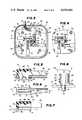
- FIG. 5is an enlarged view in vertical section taken along the line 5--5 in FIG. 3 and illustrating one of the switch modules of the present invention
- FIG. 6is a bottom plan view of the switch module illustrated in FIG. 5;
- FIG. 7is a view in vertical section taken along the line 7--7 in FIG. 6;
- FIG. 8is a further enlarged end elevational view of the switch housing of FIG. 5, as viewed from the right-hand end thereof, with the switch blades removed.
- the joystick controller 10has a two-part housing, generally designated by the numeral 11, which includes a cover or top 20 and a bottom 30 which cooperate to form a substantially closed housing.
- the cover 20has a generally rectangular top wall 21 provided around the peripheral edges thereof with a continuous depending skirt or side wall 22. Integral with the top wall 21 centrally thereof and projecting upwardly therefrom is a turret 23 which may be generally frustoconical or frustopyramidal in shape, having a circular aperture 24 in the upper end thereof.
- a support flange 25Integral with the inner surface of the turret 23 around the perimeter thereof and depending therefrom is a support flange 25 (see FIG. 2). Integral with the inner surface of the top wall 21 and depending therefrom respectively adjacent to the four corners thereof are four attachment posts 26, each having an internally threaded bore extending axially into the distal end thereof. Also integral with the inner surface of the top wall 21 and depending therefrom beneath the lower edge of the skirt 22 are two attachment posts 27, each having a reduced diameter portion 27a at the distal end thereof. The lower edge of the skirt 22 has an arcuate notch or cutout 28 therein (see FIG. 3). Also integral with the inner surface of the top wall 21 and depending therefrom are four short retaining studs 29 (see FIGS. 2 and 3), for a purpose to be explained more fully below.
- the bottom 30 of the housing 11includes a generally rectangular bottom wall 31 integral at the perimeter thereof with a continuous upstanding skirt or side wall 32.
- the edges of the skirts 22 and 32 of the cover 20 and bottom 30, respectively,are flanged for mating engagement with each other for cooperation to form a closed housing.
- Integral with the bottom wall 31 and projecting upwardly therefrom substantially normal theretoare four hollow attachment tubes 33, each being provided with a recess at the distal end thereof, the attachment tube 33 being respectively disposed for alignment with the attachment posts 26 of the cover 20. More specifically, the distal ends of the attachment posts 26 are received in the recesses in the upper ends of the attachment tubes 33.
- Fastenerssuch as screws 34 are received through the attachment tubes 33 from the lower ends thereof and are threadedly engaged with the attachment posts 26 securely to hold the cover 20 and the bottom 30 together in an assembled, closed configuration illustrated in FIGS. 1 and 2.
- a cable 37is received through the notch 28 in the cover 20, the cable 37 including a plurality of wires 38 which are electrically connected to the circuitry of the joystick controller 10 in a manner to be described more fully below.
- a handle assemblygenerally designated by the numeral 40, which includes an elongated cylindrical tube 41 extending through the aperture 24 and having a reduced diameter inner end 43 (see FIGS. 2 and 3) which extends through and is fixedly secured to a flexible diaphragm 47.
- the outer end of the tube 41extends outwardly well beyond the turret 23 and has fixedly secured thereto in surrounding relationship therewith a handle 42.
- a mounting plate 48Insert molded in the flexible diaphragm 47 is a mounting plate 48 which is fixedly secured to the lower end of the support flange 25 by suitable means (not shown).
- an actuator 44Disposed in surrounding relationship with the inner end of the reduced diameter portion 43 is an actuator 44 which is retained in place by a E-ring 45.
- the actuator 44has an arcuate contact surface 46.
- a compression spring(not shown) may be disposed in surrounding relationship with the reduced diameter portion 43 of the tube 41 between the actuator 44 and the flexible diaphragm 47 for holding the actuator 44 against the E-ring 45.
- a washer 49is disposed in surrounding relationship with the tube 41 between the flexible diaphragm 47 and the top wall of the turret 23.
- An elongated rod 50extends through the tube 41 and projects beyond the ends thereof.
- the handle 42has an axial bore 51 in the upper end thereof, into which the upper end of the rod 50 projects.
- a helical compression spring 52Disposed in the bore 51 in surrounding relationship with the upper end of the rod 50 is a helical compression spring 52, the upper end of which bears against a push button 53 which is fixedly secured to the upper end of the rod 50 and projects outwardly beyond the adjacent end of the handle 42.
- the inner end of the rod 50extends beyond the inner end of the tube 41 and has press-fitted thereonto an actuator 55.
- the compression spring 52acts to urge the rod 50 to a normal rest position, illustrated in FIG. 2, wherein the actuator 55 is held against the lower end of the tube 41.
- the joystick controller 10includes a direction control switch assembly, generally designated by the numeral 60, constructed in accordance with and embodying the features of the present invention.
- the switch assembly 60includes a flat printed circuit board 61 which is dimensioned to fit within the housing 11 substantially parallel to the top and bottom walls 21 and 31, as is best illustrated in FIGS. 2 and 3.
- the printed circuit board 61has the upper or printed surface thereof seated against the retaining studs 29, the printed circuit board 61 having holes 62, 63 and 64 therein for respectively receiving the attachment posts 26, the mounting posts 27 and the actuator 44 therethrough (see FIG. 3).
- the printed circuit board 61also has formed therethrough at equidistantly spaced-apart locations thereon, four sets of holes, each set including a small circular hole 65, a larger circular hole 66 and four slots 67 (see FIG. 5) for a purpose to be described below. Also formed in the printed circuit board 61 are a series of wire terminal holes 68 (see FIG. 3) for respectively receiving the ends of the wires 38 of the cable 37, which wire ends may then be soldered in place for connection to the printed circuit on the board 61 in a well known manner.
- each of the leaf switch modules 70includes a molded body 70A of electrically insulating plastic which includes a block 71 and fingers 82 and 83.
- the block 71is generally in the form of a regular hexahedron, and including a flat rectangular attachment surface 72 (FIG. 8) which intersects and is substantially perpendicular to a rectangular contact surface 73.
- Formed in the attachment surface 72are two spaced-apart slots or pockets 74, each of which also intercepts and opens to the contact surface 73 and is substantially perpendicular thereto.
- the slots 74are separated by a web 75 provided with tapered sides 75a at the distal edge thereof adjacent to the attachment surface 72.
- the outer sides of the slots 74are respectively bounded by side walls 76 and 77 which are parallel to the web 75 and are interconnected at the end of the block 71 opposite the contact surface 73 by an end wall portion 78.
- Integral with the attachment surface 72 and projecting therefrom substantially perpendicular theretoare a small-diameter pin 79 and a larger-diameter pin 80, the pins 79 and 80 being respectively disposed adjacent to opposite ends of the web 75.
- the body 70Ais adapted to be mounted on the under or component side of the printed circuit board 61, with the pins 79 and 80 respectively received through the holes 65 and 66, and with the attachment surface 72 flush against the printed circuit board 61.
- the pins 79 and 80have a length sufficient to extend all the way through the printed circuit board 61, the distal ends thereof then being peened over to form enlarged heads 81 (see FIG. 5) securely to hold the body 70A in place.
- the body 70Aalso includes a relatively long, flexible finger 82 integral with the contact surface 73 and projecting therefrom substantially perpendicular thereto as an extension of the side wall 76.
- the finger 82is substantially flat and rectangular, with the inner surface thereof being disposed substantially coplanar with the inner surface of the side wall 76.
- the body 70Aalso includes a relatively short, inflexible finger 83 which projects from the contact surface 73 as an extension of the side wall 77 and substantially parallel to the finger 82.
- the finger 83has a flat rectangular inner surface which is disposed substantially coplanar with the inner surface of the side wall 77. Integral with the block 71 and projecting respectively into the slots 74 are two triangular lugs 84.
- the leaf switch module 70also includes two flat leaf spring metal switch blades 85 which are respectively adapted to be disposed in the slots 74 of the block 71.
- Each of the switch blades 85has an elongated contact arm 86 provided with an embossed contact 87 adjacent to the distal end thereof.
- a triangular notch 88is formed in one edge of each switch blade 85, the opposite edge having projecting therefrom two spaced-apart flat terminal legs 89 (see FIGS. 3 and 5).
- the switch blades 85are respectively inserted in the slots 74 of the block 71, with the triangular lugs 84 being respectively received in the triangular notches 88, accurately to position the switch blades 85 in the slots 74.
- the terminal legs 89project beyond the attachment surface 72 of the block 71 and are respectively receivable through the slots 67 in the printed circuit board 61 when the body 70A is disposed in its mounted configuration with the pins 79 and 80 respectively disposed in the holes 66 and 67 in the printed circuit board 61 (see FIG. 5).
- the switch blades 85are held substantially immovably with respect to the body 70A and the printed circuit board 61.
- the contact arms 86 of the switch blades 85respectively extend along the facing inner surfaces of the fingers 82 and 83, the length of the contact arms 86 being such that they extend substantially to the end of the long finger 82.
- the switch blades 85are arranged so that the contacts 87 face each other for mutual contact.
- each of the contacts 87is in the form of an elongated oval embossment, the contacts 87 being arranged with the longitudinal axes thereof disposed substantially perpendicular to each other for more positive contact.
- the long finger 82is deflectable for deflecting the associated contact arm 86 toward the other contact arm 86 for closing the switch contacts, the short finger 83 supporting the other contact arm 86 and limiting deflection thereof.
- the switch modules 70are so arranged on the printed circuit board 61 that the outer surfaces of the long fingers 82 are respectively tangent to the arcuate contact surface 46 of the actuator 44 at equiangularly spaced-apart points thereon.
- the actuator 44deflects one or more of the long fingers 82 and the associated switch blade contact arms 86, for closing one or more of the direction control switches, as is indicated in FIG. 4, all in a well known manner.
- the joystick controller 10also includes a fire control switch 90 which is a leaf spring switch having a molded body 91, a movable contact arm 92 and fixed contact arm 93, the body 91 having bores 95 therethrough for respectively frictionally receiving therein the reduced diameter ends of the mounting posts 27 for holding the fire control switch 90 in its mounted condition (see FIGS. 2 and 3).
- the contact arms 92 and 93extend beneath the actuator 55 for engagement and operation thereby to close the contacts of the fire control switch 90 when the push button 53 is depressed in the direction of the arrow in FIG. 2.
- the direction control switch assembly 60can be preassembled as a unit, with all of the switch modules 70 mounted in place on the printed circuit board 61 and with the terminal legs 89 of the switch blades 85 soldered to the printed circuit.
- the terminal wires of the fire control switch 90can also be presoldered to the printed circuit, and the wires 38 of the cable 37 are inserted in the holes 68 and soldered to the printed circuit.
- This subassemblycan then be simply set in place in the cover 20 with the attachment posts 26 and the mounting posts 27 and the actuator 44 of the handle assembly 40 all being received through the complementary openings in the printed circuit board 61.
- the actuator 55is then press-fitted onto the end of the rod 50, and the fire control switch 90 is seated on the ends of the mounting posts 27.
- the cable 37is then fitted into the notch 28 in the cover 20, and the bottom 30 is assembled with the cover 20 to complete the closure of the housing 11.
- the fasteners 34are then applied securely to hold the housing 11 together.
Landscapes
- Physics & Mathematics (AREA)
- General Physics & Mathematics (AREA)
- Engineering & Computer Science (AREA)
- Automation & Control Theory (AREA)
- Switches With Compound Operations (AREA)
Abstract
Description
Claims (20)
Priority Applications (1)
| Application Number | Priority Date | Filing Date | Title |
|---|---|---|---|
| US06/477,128US4459440A (en) | 1983-03-21 | 1983-03-21 | Joystick and switch assembly therefor |
Applications Claiming Priority (1)
| Application Number | Priority Date | Filing Date | Title |
|---|---|---|---|
| US06/477,128US4459440A (en) | 1983-03-21 | 1983-03-21 | Joystick and switch assembly therefor |
Publications (1)
| Publication Number | Publication Date |
|---|---|
| US4459440Atrue US4459440A (en) | 1984-07-10 |
Family
ID=23894652
Family Applications (1)
| Application Number | Title | Priority Date | Filing Date |
|---|---|---|---|
| US06/477,128Expired - Fee RelatedUS4459440A (en) | 1983-03-21 | 1983-03-21 | Joystick and switch assembly therefor |
Country Status (1)
| Country | Link |
|---|---|
| US (1) | US4459440A (en) |
Cited By (36)
| Publication number | Priority date | Publication date | Assignee | Title |
|---|---|---|---|---|
| US4769517A (en)* | 1987-04-13 | 1988-09-06 | Swinney Carl M | Joystick switch assembly |
| US4816622A (en)* | 1986-11-10 | 1989-03-28 | Creative Devices Research Limited | Joystick assemblies |
| US4918265A (en)* | 1989-02-07 | 1990-04-17 | Takashi Saito | Leaf spring switch and switch assembly |
| USD330019S (en) | 1990-07-16 | 1992-10-06 | Devolpi Dean | Joy stick |
| US5823057A (en)* | 1996-08-16 | 1998-10-20 | Hsien; Ming-Kun | Joy stick structure |
| US6118086A (en)* | 1999-02-23 | 2000-09-12 | Alps Electric Co., Ltd. | Multi-directional input device |
| US20010010513A1 (en)* | 1998-06-23 | 2001-08-02 | Immersion Corporation | Tactile mouse |
| EP1215556A2 (en) | 2000-12-13 | 2002-06-19 | Marquardt GmbH | Electric switch |
| US6618036B1 (en)* | 1999-12-20 | 2003-09-09 | Mitsumi Electric Co., Ltd. | Joy stick |
| US20030201975A1 (en)* | 2002-04-25 | 2003-10-30 | David Bailey | Haptic feedback using rotary harmonic moving mass |
| US6688899B2 (en)* | 2000-10-18 | 2004-02-10 | Amphenol-Tuchel Electronics Gmbh | Smart card connector as well as switch contact elements, in particular for a smart card connector |
| US20040077406A1 (en)* | 2002-10-17 | 2004-04-22 | Alps Electric Co., Ltd. | Sense of force imparting type input device |
| US20040206611A1 (en)* | 2003-04-21 | 2004-10-21 | Alps Electric Co., Ltd. | Stalk switch |
| US20050007342A1 (en)* | 2002-04-25 | 2005-01-13 | Cruz-Hernandez Juan Manuel | Haptic devices having multiple operational modes including at least one resonant mode |
| US20050187538A1 (en)* | 2004-02-25 | 2005-08-25 | Jan Boese | Remote control device for a medical probe |
| EP1621954A1 (en) | 2004-07-28 | 2006-02-01 | Marquardt GmbH | Electrical joystick controller |
| US20060117258A1 (en)* | 2004-11-30 | 2006-06-01 | Raymond Yu | User interface device |
| EP1715401A1 (en) | 2005-04-22 | 2006-10-25 | Marquardt GmbH | Electric switch |
| EP1736846A1 (en) | 2005-06-24 | 2006-12-27 | Marquardt GmbH | Actuator, in particular of the electric switch type |
| US7249951B2 (en) | 1996-09-06 | 2007-07-31 | Immersion Corporation | Method and apparatus for providing an interface mechanism for a computer simulation |
| US20080288093A1 (en)* | 2007-05-14 | 2008-11-20 | Bokam Engineering, Inc. | Joystick controller |
| USD610098S1 (en)* | 2008-05-30 | 2010-02-16 | Asustek Computer Inc. | Joystick for a motherboard |
| US7812820B2 (en) | 1991-10-24 | 2010-10-12 | Immersion Corporation | Interface device with tactile responsiveness |
| DE10025058B4 (en)* | 1999-05-29 | 2010-10-14 | Marquardt Gmbh | Electric switch |
| EP2261765A2 (en) | 2009-06-12 | 2010-12-15 | Marquardt GmbH | Electric switch |
| DE102010023310A1 (en) | 2009-06-12 | 2010-12-16 | Marquardt Gmbh | Electric switch, particularly in form of joystick switch, cursor switch, multifunctional switch or rotary switch, has actuator, which acts together with deflecting unit |
| DE10304804B4 (en)* | 2002-02-06 | 2012-10-31 | Marquardt Gmbh | Electric multi-directional switch |
| DE102012017122A1 (en) | 2011-08-31 | 2013-02-28 | Marquardt Gmbh | Multifunctional electric switch e.g. joystick for e.g. car radio, has actuating arm that is acted on actuator during pivoting of actuator, so that pivotal movement of actuating arm is deflected into linear movement of actuator |
| DE10241869B4 (en)* | 2001-09-10 | 2017-03-23 | Marquardt Gmbh | Electric switch |
| DE102004032335B4 (en) | 2003-07-05 | 2018-11-29 | Marquardt Gmbh | Electric switch and switch arrangement |
| DE102004032337B4 (en)* | 2003-07-05 | 2019-08-29 | Marquardt Gmbh | Electric switch and steering wheel equipped therewith |
| DE102006028228B4 (en) | 2005-06-24 | 2019-09-26 | Marquardt Gmbh | Actuator for manual control of functions in a motor vehicle and electronic gear selector switch so |
| DE102004035078B4 (en)* | 2003-07-24 | 2019-11-14 | Marquardt Gmbh | Electric switch and motor vehicle with a steering wheel, on which such an electrical switch is arranged |
| US10707869B2 (en)* | 2017-05-18 | 2020-07-07 | Altec Industries, Inc. | Insulated joystick |
| US11027192B1 (en)* | 2020-02-22 | 2021-06-08 | Adam Zust | System and method for an interactive controller |
| US11822356B1 (en) | 2023-01-30 | 2023-11-21 | Altec Industries, Inc. | Aerial lift systems and control input apparatuses with high electrical resistance for use with aerial lift systems |
Citations (2)
| Publication number | Priority date | Publication date | Assignee | Title |
|---|---|---|---|---|
| US4196328A (en)* | 1978-03-18 | 1980-04-01 | Iizuka Electric Industry Company Limited | Electric switch |
| US4382166A (en)* | 1981-12-03 | 1983-05-03 | Wico Corporation | Joystick with built-in fire button |
- 1983
- 1983-03-21USUS06/477,128patent/US4459440A/ennot_activeExpired - Fee Related
Patent Citations (2)
| Publication number | Priority date | Publication date | Assignee | Title |
|---|---|---|---|---|
| US4196328A (en)* | 1978-03-18 | 1980-04-01 | Iizuka Electric Industry Company Limited | Electric switch |
| US4382166A (en)* | 1981-12-03 | 1983-05-03 | Wico Corporation | Joystick with built-in fire button |
Cited By (47)
| Publication number | Priority date | Publication date | Assignee | Title |
|---|---|---|---|---|
| US4816622A (en)* | 1986-11-10 | 1989-03-28 | Creative Devices Research Limited | Joystick assemblies |
| US4769517A (en)* | 1987-04-13 | 1988-09-06 | Swinney Carl M | Joystick switch assembly |
| US4918265A (en)* | 1989-02-07 | 1990-04-17 | Takashi Saito | Leaf spring switch and switch assembly |
| USD330019S (en) | 1990-07-16 | 1992-10-06 | Devolpi Dean | Joy stick |
| US7812820B2 (en) | 1991-10-24 | 2010-10-12 | Immersion Corporation | Interface device with tactile responsiveness |
| US5823057A (en)* | 1996-08-16 | 1998-10-20 | Hsien; Ming-Kun | Joy stick structure |
| US7249951B2 (en) | 1996-09-06 | 2007-07-31 | Immersion Corporation | Method and apparatus for providing an interface mechanism for a computer simulation |
| US20010010513A1 (en)* | 1998-06-23 | 2001-08-02 | Immersion Corporation | Tactile mouse |
| US7136045B2 (en) | 1998-06-23 | 2006-11-14 | Immersion Corporation | Tactile mouse |
| US6118086A (en)* | 1999-02-23 | 2000-09-12 | Alps Electric Co., Ltd. | Multi-directional input device |
| DE10025058B4 (en)* | 1999-05-29 | 2010-10-14 | Marquardt Gmbh | Electric switch |
| US6618036B1 (en)* | 1999-12-20 | 2003-09-09 | Mitsumi Electric Co., Ltd. | Joy stick |
| US6688899B2 (en)* | 2000-10-18 | 2004-02-10 | Amphenol-Tuchel Electronics Gmbh | Smart card connector as well as switch contact elements, in particular for a smart card connector |
| EP1215556A3 (en)* | 2000-12-13 | 2006-10-18 | Marquardt GmbH | Electric switch |
| EP1215556A2 (en) | 2000-12-13 | 2002-06-19 | Marquardt GmbH | Electric switch |
| DE10241869B4 (en)* | 2001-09-10 | 2017-03-23 | Marquardt Gmbh | Electric switch |
| DE10304804B4 (en)* | 2002-02-06 | 2012-10-31 | Marquardt Gmbh | Electric multi-directional switch |
| US20050007342A1 (en)* | 2002-04-25 | 2005-01-13 | Cruz-Hernandez Juan Manuel | Haptic devices having multiple operational modes including at least one resonant mode |
| US8576174B2 (en) | 2002-04-25 | 2013-11-05 | Immersion Corporation | Haptic devices having multiple operational modes including at least one resonant mode |
| US20030201975A1 (en)* | 2002-04-25 | 2003-10-30 | David Bailey | Haptic feedback using rotary harmonic moving mass |
| US20080170037A1 (en)* | 2002-04-25 | 2008-07-17 | Immersion Corporation | Haptic devices having multiple operational modes including at least one resonant mode |
| US7369115B2 (en) | 2002-04-25 | 2008-05-06 | Immersion Corporation | Haptic devices having multiple operational modes including at least one resonant mode |
| US7161580B2 (en)* | 2002-04-25 | 2007-01-09 | Immersion Corporation | Haptic feedback using rotary harmonic moving mass |
| US20040077406A1 (en)* | 2002-10-17 | 2004-04-22 | Alps Electric Co., Ltd. | Sense of force imparting type input device |
| US7019238B2 (en)* | 2003-04-21 | 2006-03-28 | Alps Electric Co., Ltd. | Stalk switch |
| US20040206611A1 (en)* | 2003-04-21 | 2004-10-21 | Alps Electric Co., Ltd. | Stalk switch |
| DE102004032337B4 (en)* | 2003-07-05 | 2019-08-29 | Marquardt Gmbh | Electric switch and steering wheel equipped therewith |
| DE102004032335B4 (en) | 2003-07-05 | 2018-11-29 | Marquardt Gmbh | Electric switch and switch arrangement |
| DE102004035078B4 (en)* | 2003-07-24 | 2019-11-14 | Marquardt Gmbh | Electric switch and motor vehicle with a steering wheel, on which such an electrical switch is arranged |
| US7641650B2 (en)* | 2004-02-25 | 2010-01-05 | Siemens Aktiengesellschaft | Remote control device for a medical probe |
| US20050187538A1 (en)* | 2004-02-25 | 2005-08-25 | Jan Boese | Remote control device for a medical probe |
| EP1621954A1 (en) | 2004-07-28 | 2006-02-01 | Marquardt GmbH | Electrical joystick controller |
| US7456821B2 (en) | 2004-11-30 | 2008-11-25 | Immersion Corporation | User interface device |
| US20060117258A1 (en)* | 2004-11-30 | 2006-06-01 | Raymond Yu | User interface device |
| EP1715401A1 (en) | 2005-04-22 | 2006-10-25 | Marquardt GmbH | Electric switch |
| EP1736846A1 (en) | 2005-06-24 | 2006-12-27 | Marquardt GmbH | Actuator, in particular of the electric switch type |
| DE102006028228B4 (en) | 2005-06-24 | 2019-09-26 | Marquardt Gmbh | Actuator for manual control of functions in a motor vehicle and electronic gear selector switch so |
| US8502776B2 (en) | 2007-05-14 | 2013-08-06 | Bokam Engineering, Inc. | Joystick controller |
| US20080288093A1 (en)* | 2007-05-14 | 2008-11-20 | Bokam Engineering, Inc. | Joystick controller |
| USD610098S1 (en)* | 2008-05-30 | 2010-02-16 | Asustek Computer Inc. | Joystick for a motherboard |
| EP2261765A2 (en) | 2009-06-12 | 2010-12-15 | Marquardt GmbH | Electric switch |
| DE102010023310A1 (en) | 2009-06-12 | 2010-12-16 | Marquardt Gmbh | Electric switch, particularly in form of joystick switch, cursor switch, multifunctional switch or rotary switch, has actuator, which acts together with deflecting unit |
| DE102012017122A1 (en) | 2011-08-31 | 2013-02-28 | Marquardt Gmbh | Multifunctional electric switch e.g. joystick for e.g. car radio, has actuating arm that is acted on actuator during pivoting of actuator, so that pivotal movement of actuating arm is deflected into linear movement of actuator |
| DE102012017122B4 (en) | 2011-08-31 | 2024-08-08 | Marquardt Gmbh | Electrical switch |
| US10707869B2 (en)* | 2017-05-18 | 2020-07-07 | Altec Industries, Inc. | Insulated joystick |
| US11027192B1 (en)* | 2020-02-22 | 2021-06-08 | Adam Zust | System and method for an interactive controller |
| US11822356B1 (en) | 2023-01-30 | 2023-11-21 | Altec Industries, Inc. | Aerial lift systems and control input apparatuses with high electrical resistance for use with aerial lift systems |
Similar Documents
| Publication | Publication Date | Title |
|---|---|---|
| US4459440A (en) | Joystick and switch assembly therefor | |
| US4492830A (en) | Joystick with single-leaf spring switch | |
| US4582967A (en) | Key switch assembly | |
| US5783787A (en) | Electrical switch assembly | |
| US5950812A (en) | Rocker switch using a star spring | |
| US6248966B1 (en) | Lever switch and method of operating the same | |
| KR960030755A (en) | Conductive contact | |
| US6339201B1 (en) | Four function electrical rocker switch | |
| US4429200A (en) | Low cost, high performance switch assembly | |
| US4197437A (en) | Snap-action switch | |
| US4814554A (en) | Switch assembly with redundant spring force and one-piece plunger | |
| US5570778A (en) | Electrical rocker switch | |
| FR2637422A3 (en) | CONNECTING BODY | |
| US4853505A (en) | Miniature illuminated rocker switch | |
| KR910019080A (en) | Illuminated pushbutton | |
| US4837411A (en) | Spring switch | |
| US4022999A (en) | Plural-circuit progressive switch | |
| US4874911A (en) | Electrical reversing switch | |
| JPH07272594A (en) | Assembling structure of lever switch | |
| JPH0335768B2 (en) | ||
| US4383149A (en) | Push-button switch with improved rocking contactor switch mechanism | |
| US5496981A (en) | Electrical switch | |
| US4133993A (en) | Momentary contact switch with compensating spring | |
| KR0143422B1 (en) | Switch | |
| US4926012A (en) | Miniature electric switch designed to be used in particular in printed circuits |
Legal Events
| Date | Code | Title | Description |
|---|---|---|---|
| AS | Assignment | Owner name:WICO CORPORATION; NILES, IL. A CORP OF IL. Free format text:ASSIGNMENT OF ASSIGNORS INTEREST.;ASSIGNOR:WICZER, MAX;REEL/FRAME:004110/0349 Effective date:19830311 | |
| AS | Assignment | Owner name:J. HENRY SCHRODER BANK & TRUST COMPANY, ONE STATE Free format text:SECURITY INTEREST;ASSIGNOR:WICO DISTRIBUTION COMPANY, L.P., A DELAWARE LIMITED PARTNERSHIP BY WICO HOLDING CORP., GENERAL PARTNER;REEL/FRAME:004599/0762 Effective date:19860711 Owner name:J. HENRY SCHRODER BANK & TRUST COMPANY, A NY. CORP Free format text:SECURITY INTEREST;ASSIGNOR:WICO DISTRIBUTION COMPANY, L.P., A DELAWARE LIMITED PARTNERSHIP BY WICO HOLDING CORP., GENERAL PARTNER;REEL/FRAME:004599/0762 Effective date:19860711 | |
| AS | Assignment | Owner name:WICO DISTRIBUTION COMPANY, L.P., 6400 WEST GROSS P Free format text:ASSIGNMENT OF ASSIGNORS INTEREST. AS OF JULY 11, 1986;ASSIGNOR:WICO CORPORATION, AN IL CORP.;REEL/FRAME:004608/0125 Effective date:19860711 Owner name:WICO DISTRIBUTION COMPANY, L.P., 6400 WEST GROSS P Free format text:ASSIGNMENT OF ASSIGNORS INTEREST;ASSIGNOR:WICO CORPORATION, AN IL CORP.;REEL/FRAME:004608/0125 Effective date:19860711 | |
| FPAY | Fee payment | Year of fee payment:4 | |
| AS | Assignment | Owner name:WICO DISTRIBUTION CORP., A DE CORP., ILLINOIS Free format text:ASSIGNMENT OF ASSIGNORS INTEREST.;ASSIGNOR:WICO DISTRIBUTION COMPANY, L.P.;REEL/FRAME:005001/0133 Effective date:19881221 | |
| AS | Assignment | Owner name:BT COMMERCIAL CORPORATION, A CORP. OF NY. Free format text:SECURITY INTEREST;ASSIGNOR:WICO DISTRIBUTION CORP.;REEL/FRAME:005036/0898 Effective date:19880831 | |
| AS | Assignment | Owner name:NATIONAL WESTMINSTER BANK USA, NEW YORK Free format text:SECURITY INTEREST;ASSIGNOR:WICO DISTRIBUTION CORP., A CORP. OF DE;REEL/FRAME:005216/0295 Effective date:19890614 Owner name:WICO DISTRIBUTION CORP., A DE CORP. Free format text:RELEASED BY SECURED PARTY;ASSIGNOR:BT COMMERCIAL CORPORATION;REEL/FRAME:005216/0312 Effective date:19880831 | |
| REMI | Maintenance fee reminder mailed | ||
| LAPS | Lapse for failure to pay maintenance fees | ||
| FP | Lapsed due to failure to pay maintenance fee | Effective date:19920712 | |
| STCH | Information on status: patent discontinuation | Free format text:PATENT EXPIRED DUE TO NONPAYMENT OF MAINTENANCE FEES UNDER 37 CFR 1.362 |