US4458821A - Tamper-indicating closure - Google Patents
Tamper-indicating closureDownload PDFInfo
- Publication number
- US4458821A US4458821AUS06/448,064US44806482AUS4458821AUS 4458821 AUS4458821 AUS 4458821AUS 44806482 AUS44806482 AUS 44806482AUS 4458821 AUS4458821 AUS 4458821A
- Authority
- US
- United States
- Prior art keywords
- annular
- tamper
- closure
- frangible
- indicating
- Prior art date
- Legal status (The legal status is an assumption and is not a legal conclusion. Google has not performed a legal analysis and makes no representation as to the accuracy of the status listed.)
- Expired - Lifetime
Links
Images


Classifications
- B—PERFORMING OPERATIONS; TRANSPORTING
- B29—WORKING OF PLASTICS; WORKING OF SUBSTANCES IN A PLASTIC STATE IN GENERAL
- B29C—SHAPING OR JOINING OF PLASTICS; SHAPING OF MATERIAL IN A PLASTIC STATE, NOT OTHERWISE PROVIDED FOR; AFTER-TREATMENT OF THE SHAPED PRODUCTS, e.g. REPAIRING
- B29C57/00—Shaping of tube ends, e.g. flanging, belling or closing; Apparatus therefor, e.g. collapsible mandrels
- B—PERFORMING OPERATIONS; TRANSPORTING
- B65—CONVEYING; PACKING; STORING; HANDLING THIN OR FILAMENTARY MATERIAL
- B65D—CONTAINERS FOR STORAGE OR TRANSPORT OF ARTICLES OR MATERIALS, e.g. BAGS, BARRELS, BOTTLES, BOXES, CANS, CARTONS, CRATES, DRUMS, JARS, TANKS, HOPPERS, FORWARDING CONTAINERS; ACCESSORIES, CLOSURES, OR FITTINGS THEREFOR; PACKAGING ELEMENTS; PACKAGES
- B65D41/00—Caps, e.g. crown caps or crown seals, i.e. members having parts arranged for engagement with the external periphery of a neck or wall defining a pouring opening or discharge aperture; Protective cap-like covers for closure members, e.g. decorative covers of metal foil or paper
- B65D41/32—Caps or cap-like covers with lines of weakness, tearing-strips, tags, or like opening or removal devices, e.g. to facilitate formation of pouring openings
- B65D41/34—Threaded or like caps or cap-like covers provided with tamper elements formed in, or attached to, the closure skirt
- B65D41/3423—Threaded or like caps or cap-like covers provided with tamper elements formed in, or attached to, the closure skirt with flexible tabs, or elements rotated from a non-engaging to an engaging position, formed on the tamper element or in the closure skirt
- B65D41/3428—Threaded or like caps or cap-like covers provided with tamper elements formed in, or attached to, the closure skirt with flexible tabs, or elements rotated from a non-engaging to an engaging position, formed on the tamper element or in the closure skirt the tamper element being integrally connected to the closure by means of bridges
- B—PERFORMING OPERATIONS; TRANSPORTING
- B29—WORKING OF PLASTICS; WORKING OF SUBSTANCES IN A PLASTIC STATE IN GENERAL
- B29C—SHAPING OR JOINING OF PLASTICS; SHAPING OF MATERIAL IN A PLASTIC STATE, NOT OTHERWISE PROVIDED FOR; AFTER-TREATMENT OF THE SHAPED PRODUCTS, e.g. REPAIRING
- B29C53/00—Shaping by bending, folding, twisting, straightening or flattening; Apparatus therefor
- B29C53/02—Bending or folding
- B—PERFORMING OPERATIONS; TRANSPORTING
- B29—WORKING OF PLASTICS; WORKING OF SUBSTANCES IN A PLASTIC STATE IN GENERAL
- B29L—INDEXING SCHEME ASSOCIATED WITH SUBCLASS B29C, RELATING TO PARTICULAR ARTICLES
- B29L2031/00—Other particular articles
- B29L2031/56—Stoppers or lids for bottles, jars, or the like, e.g. closures
- B29L2031/565—Stoppers or lids for bottles, jars, or the like, e.g. closures for containers
- B—PERFORMING OPERATIONS; TRANSPORTING
- B65—CONVEYING; PACKING; STORING; HANDLING THIN OR FILAMENTARY MATERIAL
- B65D—CONTAINERS FOR STORAGE OR TRANSPORT OF ARTICLES OR MATERIALS, e.g. BAGS, BARRELS, BOTTLES, BOXES, CANS, CARTONS, CRATES, DRUMS, JARS, TANKS, HOPPERS, FORWARDING CONTAINERS; ACCESSORIES, CLOSURES, OR FITTINGS THEREFOR; PACKAGING ELEMENTS; PACKAGES
- B65D2401/00—Tamper-indicating means
- B65D2401/15—Tearable part of the closure
- B65D2401/30—Tamper-ring remaining connected to closure after initial removal
- B—PERFORMING OPERATIONS; TRANSPORTING
- B65—CONVEYING; PACKING; STORING; HANDLING THIN OR FILAMENTARY MATERIAL
- B65D—CONTAINERS FOR STORAGE OR TRANSPORT OF ARTICLES OR MATERIALS, e.g. BAGS, BARRELS, BOTTLES, BOXES, CANS, CARTONS, CRATES, DRUMS, JARS, TANKS, HOPPERS, FORWARDING CONTAINERS; ACCESSORIES, CLOSURES, OR FITTINGS THEREFOR; PACKAGING ELEMENTS; PACKAGES
- B65D2401/00—Tamper-indicating means
- B65D2401/15—Tearable part of the closure
- B65D2401/35—Vertical or axial lines of weakness
- B—PERFORMING OPERATIONS; TRANSPORTING
- B65—CONVEYING; PACKING; STORING; HANDLING THIN OR FILAMENTARY MATERIAL
- B65D—CONTAINERS FOR STORAGE OR TRANSPORT OF ARTICLES OR MATERIALS, e.g. BAGS, BARRELS, BOTTLES, BOXES, CANS, CARTONS, CRATES, DRUMS, JARS, TANKS, HOPPERS, FORWARDING CONTAINERS; ACCESSORIES, CLOSURES, OR FITTINGS THEREFOR; PACKAGING ELEMENTS; PACKAGES
- B65D2401/00—Tamper-indicating means
- B65D2401/15—Tearable part of the closure
- B65D2401/40—Bridges having different cross-sections
Definitions
- tamper-indicating closuresin which the closure is of a thermoplastic material, is receiving wide acceptability in the marketplace. Such closures will become even more market dominant upon their acceptance by the carbonated beverage industry.
- Exemplary of various types of tamper-indicating closuresare the ones shown in U.S. Pat. Nos. 3,329,295, 3,438,528, 3,784,041, 4,126,240, 4,147,268, 4,196,818, 4,206,851, and 4,305,516.
- thermoplastic closure of this inventioncan be produced by conventional injection-molding techniques.
- a particularly useful thermoplastic material, from which the closures of this invention can be made,is polypropylene.
- other thermoplastic materialsmay be useful such as polyethylene terephthalate, high-density polyethylene, nylon, polyvinyl chloride, etc.
- the closure of this inventionfeatures a conventional top wall and an annular sidewall downwardly depending therefrom. About the inside surface of the annular sidewall, there is provided a closure thread for cooperation with the container thread to achieve fitment of the closure to the container. Connected to the lower end of the annular sidewall is an annular tamper-indicating band. This connection is made by way of an annular area which comprises a frangible portion and a non-frangible portion. The annular tamper-indicating band is dimensioned, along with the annular area and the annular sidewall, so that the band will at least partially extend to a point beneath the container's outwardly extending annular flange when the closure is fitted to the container.
- the annular areacan be of any configuration which allows for fracturing of the frangible portion upon attempted removal of the closure from the container but does not allow for fracturing in the non-frangible portion.
- a preferred configurationfeatures a plurality of spaced apart fracturable bridges which comprise the frangible portion and a non-fracturable bridge which comprises the non-frangible portion. Fracture of the frangible portion results in only partial separation of the annular tamper-indicating band from the closure's annular sidewall since the non-frangible portion will keep the tamper-indicating band attached to the closure annular sidewall.
- the frangible portionis represented by spaced-apart bridges, they are dimensioned so that they will lack sufficient strength to maintain their integrity upon attempted removal of the closure from the container but are sufficiently strong to resist fracturing when the closure is fitted to the container.
- the annular tamper-indicating bandfeatures an annular upper portion which depends downwardly from the annular area.
- the bandadditionally has an annular lower portion which comprises a plurality of spaced-apart tabs with each tab connected to its neighboring tab by way of a flexible web.
- Each of the tabscan optionally have a scalloped recess at their lower extent to improve circumferential flexibility when the annular lower portion is hinged from its molded position to its utilitarian position as hereinafter described.
- an annular hingecan be provided by a continuous thinned wall web or it can be provided by a plurality of thinned wall hinges which are separated one from the other by slots or openings.
- the tamper-indicating bandwill have its own frangible area which extends axially through the annular upper and lower portions and the flexible web.
- This vertical or axial frangible areais dimensioned to fracture upon removal of the closure from the container at a time subsequent to the fracture of at least a part of the frangible portion of the before-described annular area.
- FIG. 1is a sectional view of a closure of this invention fitted to a container
- FIG. 2is a sectional view of the closure shown in FIG. 1 as the closure is removed from the container;
- FIG. 3is a partial enlarged sectional view of the closure shown in FIG. 1 with the tamper-indicating band at its midway point as it is turned inwardly;
- FIG. 4is a partial enlarged sectional view of the closure shown in FIG. 1 showing the position of the tamper-indicating band after it has been hinged inwardly;
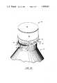
- FIG. 5is a perspective view of the closure shown in FIG. 1;
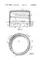
- FIG. 6is a sectional view taken through sectional line 6--6 in FIG. 5;
- FIG. 7is a bottom plan view of the closure shown in FIG. 1;
- FIG. 8is a sectional view showing a second closure of this invention fitted to a container
- FIG. 9is a sectional view of the closure shown in FIG. 8 as the closure is removed from the container;
- FIG. 10is a partial enlarged sectional view of the closure shown in FIG. 8 with the tamper-indicating band at its midway point, as it is turned inwardly;
- FIG. 11is a partial enlarged sectional view of the closure shown in FIG. 8 showing the position of the tamper-indicating band after it has been hinged inwardly;
- FIG. 12is a perspective view of the closure shown in FIG. 8;
- FIG. 13is a sectional view taken through a sectional line 6--6 in FIG. 8;
- FIG. 14is a bottom plan view of the closure shown in FIG. 8;
- FIG. 15is a perspective view of the closure shown in FIG. 1 showing the closure as it is removed from the container.
- FIGS. 1-7 and 15there can be seen a package, generally designated by the numeral 10, composed of a closure of this invention, generally designated by the numeral 12, and a container, generally designated by the numeral 14.
- Container 14can be of any conventional material, for example, it may be of a thermoplastic material such as polyvinyl chloride, polyethylene terephthalate, polyethylene, etc., or it may be of glass.
- Container 14has a neck portion which carries on its outside wall a helical thread 16. Beneath, but adjacent to helical thread 16, is annular outwardly extending flange 18. Note that annular flange 18 has an upper outer annular surface which is sloped downwardly and outwardly to meet an essentially horizontal lower annular surface. Such a configuration is advantageous when utilizing closures of this invention as hereinafter described.
- Closure 12has a circular top wall 20 and an annular downwardly depending sidewall 22. About the inside surface of annular sidewall 22 is a helical closure thread 24. Closure thread 24 is configured and dimensioned to be cooperative with container thread 16 to achieve fitment of cap 12 onto container 14. Nested against the inside surface of top wall 20 is liner 21. Liner 21 is utilized to effect a seal between closure 12 and the mouth of container 14 as is seen in FIG. 1. However, it should be realized that the closures of this invention are not limited to the utilization of a liner to effect this sealing but that the closures can also utilize linerless sealing systems which are well-known to those skilled in the art. Generally speaking, such linerless systems utilize downwardly extending fins which emanate from the inside surface of top wall 20, or at the juncture of top wall 20 and annular sidewall 22. These fins coact with the mouth portion of container 14 to achieve the desired seal.
- Closure 12has integrally formed with sidewall 22, annular tamper-indicating band 26. Annular tamper-indicating band 26 is attached to sidewall 22 by way of annular area 28. Annular area 28 has frangible portion 15, hereinafter described, of reduced strength which is designed to fracture in accordance with the tamper-indicating operation of closure 12. Annular area 28 also has a non-frangible portion 13. For the embodiments shown in the drawings, frangible portion 15 is formed by a plurality of slots 32 which alternate with a plurality of fracturable bridges 30. The width and depth of fracturable bridges 30 is dependent upon the expected stresses to be applied thereto upon closure opening and upon the material which closure 12 is made.
- fracturable bridges 30can be designed to have a width of from about 0.020 to about 0.030 inches and a depth of from about 0.007 to about 0.010 inches.
- the configuration and dimensions of fracturable bridges 30is best determined by empirically testing the closure on a container and under the conditions expected to be encountered in the marketplace.
- Frangible portion 15may also have other configurations.
- this areamay be formed by a groove cut into the outside of the closure sidewall.
- the groovedefines an area of reduced thickness and thus would represent a zone of weakness capable of shearing upon removal of closure 12 from container 14.
- Other frangible area configurationsmay be used since the particular configuration is not critical to the operation of the closures of this invention so long as the frangible area is capable of shearing or fracturing under conventionally expected removal forces.
- annular tamper-indicating band 26Immediately below annular area 28 is annular tamper-indicating band 26.
- Annular tamper-indicating band 26has an annular upper portion 34 attached to annular lower portion 38 by way of annular hinge 36.
- Annular hinge 36is an annular area of reduced thickness which allows for flexing along the annular line defined by annular hinge 36.
- the thickness of annular hinge 36is dependent upon the material from which closure 12 is made. Some thermoplastic materials will exhibit greater resistance to bending and thus need to be made fairly thin. Other thermoplastic materials, however, are easier to bend but need a greater thickness to guard against stress fracture. It has been found that when utilizing polypropylene as the material of construction for closure 12, that annular hinge 36 should have a thickness within the range of from about 0.008 to about 0.014 inches.
- Annular lower portion 38is comprised of a plurality of spaced apart tabs 40 which are connected by way of flexible webs 42. At the lower portion of each tab 40, for the embodiment shown, there is a scalloped recess 44. Scalloped recesses 44 can be either angular or arcuate. The arcuate form is used for the embodiments shown in the drawings.
- annular tamper-indicating band 26has a vertical frangible area 17.
- frangible arearepresents a weakened line extending across annular upper portion 34, annular hinge 36 and annular lower portion 38.
- Vertical frangible area 17is preferably generally opposite non-frangible portion 13.
- Frangible area 17is best formed by providing that the annular upper and lower portions on the annular hinge each have an area of reduced thickness. The ultimate reduction in thickness for each of the portions and the hinge to achieve fracturing of the tamper-indicating band upon closure removal will be dependent on the material of closure construction. For polypropylene, the reduced thickness will be in the range of from about 0.006 to about 0.012 inches.
- annular hinge 36 or annular lower portion 38 at frangible area 17have thicknesses within this range, they need not be further reduced in thickness.
- non-frangible area 13 and vertical frangible area 17the removal of tamper-indicating band 26 with the removal of the rest of the closure from container 14 is assured. Such removal is advantageous when container 14 is a returnable container as the bottlers will not have the added expense of removing tamper-indicating band 26 from a returned container before the refilling of same.
- closures of this inventionare the paragon of simplicity. As is shown in FIG. 5, closure 12 is molded so that annular tamper-indicating band 26 is in the down position. To prepare closure 12 for use on container 14, it is necessary to fold inwardly and upwardly lower portion 38. The folding will occur about annular hinge 36. This inward and upward fold requires that annular lower portion 38 have the circumferential flexibility to accommodate the varying circumferences encountered as it moves from its molded position, shown in FIG. 5, through the intermediate position shown in FIG. 3 and the final at rest position shown in FIG. 4. As can be seen in FIG. 3, the inward folding of annular lower portion 38 results in its having a reduced circumference at its end most distal from annular hinge 36.
- annular hinge 36is a stress position and thus, considerable force must be utilized to go through that position.
- the resiliency in annular hinge 36is not sufficient to effect such movement of annular lower portion 38.
- Annular lower portion 38therefore is held in the position shown in FIGS. 1, 2 and 4.
- annular lower portion 38is positioned slightly outwardly from the inside surface of sidewall 22. This position can be encouraged by the placing of annular hinge 36 outside of the inside wall of annular upper portion 34 so that the lower inside part of annular upper portion 34 abuts against tabs 40 as shown in FIG. 4 at "Y".
- This positioning of annular lower portion 38 inwardly of the inside surface of the closure sidewallis advantageous in that it ensures that tabs 40 of annular lower portion 38 make good interfering contact with annular container flange 18.
- This interfering contactcan be achieved without displacement of annular lower portion 38 from the inside surface of sidewall 22 by providing projections on the tab and/or on the lower inside part of annular upper portion 34. These projections will provide the interfering contact which is desired.
- annular lower portion 38is accomplished after the injection molding of closure 12. This inward folding can be accomplished by utilization of simple punching means as is well known to those skilled in the art.
- annular lower portion 38Once annular lower portion 38 has been folded inwardly to the position shown in FIGS. 1 and 4, the closure can be simply screwed onto container 14. As closure 12 is screwed onto container 14, annular lower portion 38 will make contact with annular container flange 18. Since annular container flange 18 has a downwardly sloped upper annular surface to act as a cam surface and annular lower portion 38 is resiliently hinged, passage of annular lower portion 38 thereover is facilitated without the realization of great stress in annular frangible area 28. By having annular lower portion 38 resiliently hinged, a spring action is realized as annular lower portion 38 passes over annular container flange 18. Therefore, annular lower portion 38 is able to flex resiliently away from container annular flange 18 thereby mitigating stress caused by the passage of annular lower portion 38 over annular container flange 18.
- annular lower portion 38After closure 12 has been fitted to container 14, it can be seen that the distal end of annular lower portion 38 is in abutment against the horizontal lower annular surface of annular flange 18. This position assures an interfering fit between the horizontal lower annular surface and annular lower portion 38 which can only be overcome by forces which are larger than can be withstood by annular frangible area 38. Further, since the forces of removal bear on annular lower portion 38 through its vertical width it is placed in compression, and since annular lower portion 38 is strongest against deformation due to compression the rigidity of the interfering fit is enhanced during closure removal.
- closure 12will move axially and upward in response to the unthreading torque.
- Annular tamper-indicating band 26, however,is blocked from such axial upward movement due to the before-mentioned interference between triangular projections 44 and the horizontal lower annular surface of annular flange 18.
- tension forcesbeing realized throughout the entire closure sidewall area.
- frangible portion 15 of annular area 28is the weakest link throughout the closure sidewall area, a fracture will ultimately occur there (see FIGS. 2 and 15).
- non-frangible area 13holds to tamper-indicating band 26.
- Continued unthreading of the closuretherefore causes a continued pull axially upward on tamper-indicating band 26.
- tamper-indicating band 26can expand outwardly so that the position of interference between container flange 18 and triangular projections 44 is for the most part lost. Thus, continued removal of closure 12 along with tamper-indicating band 26 can occur. The tamper-indicating function is achieved as the various fractures are readily seen by the consumer. Since tamper-indicating band 26 is still attached to the rest of the closure, via non-frangible area 13, container 14 can be simply cleaned, sterilized and refilled without concern for removal from the container of tamper-indicating band 26.
- FIGS. 8-14Another closure embodiment of this invention is shown in FIGS. 8-14.
- the closure shown in FIGS. 8-14is identical in many respects with the closure shown in FIGS. 1-7 and thus, for convenience's sake, the description made for some parts in discussing FIGS. 1-7 is equally applicable to the identical part shown in FIGS. 8-14 and therefore, will not be repeated.
- the identical partsare designated by the same numbers for both embodiments.
- closure 50differs from closure 12, shown in FIGS. 1-7, as the former closure has a differently configured annular hinge 54.
- annular hinge 54is formed by a plurality of spaced-apart hinged segments 55 which are separated by gaps 56. It has been found that by providing gaps 56 between hinged segments 55 that a more flexible annular hinge 54 can be effected.
- Hinged segments 55connect to tabs 40 at the tab upper shoulders. Note that hinged segments 55 connect the upper right shoulder, designated by the letter "a”, of one tab to the upper left shoulder, designated by the letter "b", of a neighboring tab. Such a positioning of hinged segments 55 is necessary so as to maintain structural integrity in annular tamper-indicating band 26.
- closure 50operates in the same manner as does closure 12 described above.
Landscapes
- Engineering & Computer Science (AREA)
- Mechanical Engineering (AREA)
- Closures For Containers (AREA)
Abstract
Description
Claims (21)
Priority Applications (1)
| Application Number | Priority Date | Filing Date | Title |
|---|---|---|---|
| US06/448,064US4458821A (en) | 1982-12-09 | 1982-12-09 | Tamper-indicating closure |
Applications Claiming Priority (1)
| Application Number | Priority Date | Filing Date | Title |
|---|---|---|---|
| US06/448,064US4458821A (en) | 1982-12-09 | 1982-12-09 | Tamper-indicating closure |
Publications (1)
| Publication Number | Publication Date |
|---|---|
| US4458821Atrue US4458821A (en) | 1984-07-10 |
Family
ID=23778874
Family Applications (1)
| Application Number | Title | Priority Date | Filing Date |
|---|---|---|---|
| US06/448,064Expired - LifetimeUS4458821A (en) | 1982-12-09 | 1982-12-09 | Tamper-indicating closure |
Country Status (1)
| Country | Link |
|---|---|
| US (1) | US4458821A (en) |
Cited By (50)
| Publication number | Priority date | Publication date | Assignee | Title |
|---|---|---|---|---|
| US4511054A (en)* | 1984-04-13 | 1985-04-16 | Kerr Glass Manufacturing Corporation | Tamper-evident closure and method of manufacture |
| US4519516A (en)* | 1984-01-26 | 1985-05-28 | Owens-Illinois, Inc. | Tamper indicating package |
| US4530436A (en)* | 1981-12-11 | 1985-07-23 | Walter Wiedmer | Screw cap with guarantee strip for container |
| DE3535521A1 (en)* | 1984-10-22 | 1986-04-24 | Owens-Illinois, Inc., Toledo, Ohio | Improved carrier for bottles |
| US4749095A (en)* | 1987-05-28 | 1988-06-07 | Owens-Illinois Closure Inc. | Tamper-indicating closure and package |
| US4796770A (en)* | 1987-10-05 | 1989-01-10 | Continental White Cap, Inc. | Molded plastic closure with split skirt tamperband |
| US4981230A (en)* | 1990-03-15 | 1991-01-01 | Continental White Cap, Inc. | Composite cap including tamper indicating band |
| US5007545A (en)* | 1990-03-15 | 1991-04-16 | Seaquist Closures | Removal resistant member |
| US5050753A (en)* | 1990-08-27 | 1991-09-24 | H-C Industries, Inc. | Preferentially strengthened tamper-indicating plastic closure |
| US5253772A (en)* | 1991-05-21 | 1993-10-19 | Sweetheart Cup Company, Inc. | Tamper evident container assembly |
| US5295600A (en)* | 1993-02-25 | 1994-03-22 | Owens-Illinois Closure Inc. | Tamper indicating closure |
| EP0616951A1 (en)* | 1993-03-26 | 1994-09-28 | Owens-Illinois Closure Inc., | Tamper indicating package |
| EP0641721A1 (en)* | 1993-09-03 | 1995-03-08 | Novembal | Screwcap with tamper evidence band, package provided with such a cap, method of making such a cap and such a package |
| FR2709473A1 (en)* | 1993-09-03 | 1995-03-10 | Novembal Sa | Screw cap and tamper-evident ring, package provided with such a cap, method of manufacturing such a cap and such a package |
| US5397009A (en)* | 1992-05-29 | 1995-03-14 | Novembal | Break-away safety cap for containers |
| US5456374A (en)* | 1994-09-19 | 1995-10-10 | Beck; Matthew R. | Tamper evident container closure |
| US5490827A (en)* | 1991-05-21 | 1996-02-13 | Sweetheart Cup Company, Inc. | Tamper evident container and related apparatus |
| US5564582A (en)* | 1992-10-07 | 1996-10-15 | H-C Industries, Inc. | Tamper-indicating plastic closure with pilfer band having staggered scores |
| US5570798A (en)* | 1994-05-17 | 1996-11-05 | Mikasa Industry Co., Inc. | Container opening/closing device |
| US5575967A (en)* | 1995-02-17 | 1996-11-19 | Sunbeam Plastics Corporation | Method of forming a tamper indicating closure |
| US5658228A (en)* | 1992-04-30 | 1997-08-19 | Sweetheart Cup Company, Inc. | Tamper evident container and related apparatus |
| US5660288A (en)* | 1995-01-20 | 1997-08-26 | Kerr Group, Inc. | Reverse helix tamper-evident container |
| US5680965A (en)* | 1996-01-29 | 1997-10-28 | Beck; Matthew R. | Tamper evident container closure |
| US5853095A (en)* | 1992-12-18 | 1998-12-29 | White Cap, Inc. | Tamper evident splitting closure |
| US6053344A (en)* | 1998-07-02 | 2000-04-25 | Owens-Illinois Closure Inc. | Tamper-indicating closure and method of manufacture |
| US6116442A (en)* | 1997-04-17 | 2000-09-12 | Amcor Limited | Tamper indicating closure |
| US6119883A (en)* | 1998-12-07 | 2000-09-19 | Owens-Illinois Closure Inc. | Tamper-indicating closure and method of manufacture |
| US6152316A (en)* | 1999-05-17 | 2000-11-28 | Owens-Illinois Closure Inc. | Tamper-indicating closure and method of manufacture |
| US6371317B1 (en) | 1998-08-07 | 2002-04-16 | Kerr Group, Inc. | Tamper indicating closure with foldable tab |
| US6382443B1 (en) | 1999-04-28 | 2002-05-07 | Owens-Illinois Closure Inc. | Tamper-indicating closure with lugs on a stop flange for spacing the flange from the finish of a container |
| US20050011855A1 (en)* | 2002-04-11 | 2005-01-20 | Zapata Felipe Lopez | Tamper-proof cap for bottles |
| WO2005012125A1 (en)* | 2003-08-04 | 2005-02-10 | Abacus (C.I.) Limited As Trustee Of The Bayview Trust | Closure with frangible tamper-evident band |
| WO2005077777A1 (en)* | 2004-02-18 | 2005-08-25 | Abacus (C.I.) Limited As Trustee Of The Bayview Trust | Closure with frangible tamper-evident band |
| US20050189312A1 (en)* | 1998-08-07 | 2005-09-01 | Bixler Frederick L. | Tamper indicating closure with foldable tab |
| GB2420114A (en)* | 2003-01-14 | 2006-05-17 | Abacus | Closure with frangible tamper-evident band |
| US20060169666A1 (en)* | 2005-01-31 | 2006-08-03 | Nyman Henry H | Anti-backoff, low application torque, tamper evident plastic closure and container system with enhanced visual tamper evidency |
| US20120091134A1 (en)* | 2010-10-15 | 2012-04-19 | Sohail Sadiq | Tamper-evident closure and package |
| ITMO20100359A1 (en)* | 2010-12-21 | 2012-06-22 | Sacmi | SCREW CAP |
| CN102596541A (en)* | 2009-10-23 | 2012-07-18 | 雀巢产品技术援助有限公司 | A closure |
| US20120223103A1 (en)* | 2009-11-19 | 2012-09-06 | Valois Sas | Dispenser of fluid material |
| US20130206136A1 (en)* | 2010-06-24 | 2013-08-15 | Boehringer Ingelheim International Gmbh | Nebulizer |
| US20140263356A1 (en)* | 2013-03-15 | 2014-09-18 | Sonoco Development, Inc. | Closure for container |
| USD723919S1 (en) | 2013-10-24 | 2015-03-10 | Silgan White Cap LLC | Closure |
| US11059633B2 (en) | 2019-10-31 | 2021-07-13 | Cheer Pack North America | Flip-top closure for container |
| US11273962B2 (en) | 2014-02-14 | 2022-03-15 | Closure Systems International Inc. | Tamper-evident closure |
| US11603237B2 (en) | 2019-10-07 | 2023-03-14 | Closure Systems International Inc. | Flip-top closure |
| USD996968S1 (en) | 2021-05-17 | 2023-08-29 | Closure Systems International Inc. | Closure |
| USD996967S1 (en) | 2021-05-17 | 2023-08-29 | Closure Systems International Inc. | Closure |
| USD1063613S1 (en) | 2020-09-28 | 2025-02-25 | Closure Systems International Inc. | Closure with tamper-evident band |
| USD1063612S1 (en) | 2020-09-28 | 2025-02-25 | Closure Systems International Inc. | Closure with tamper-evident band |
Citations (13)
| Publication number | Priority date | Publication date | Assignee | Title |
|---|---|---|---|---|
| US3374913A (en)* | 1965-10-08 | 1968-03-26 | Continental Can Co | Tamper-proof package |
| US3484012A (en)* | 1968-01-22 | 1969-12-16 | Continental Can Co | Tamper-proof package |
| DE2213773A1 (en)* | 1972-03-22 | 1973-09-27 | Vinzenz Boehm | TELEPHONE NUMBER DIRECTORY |
| US3861551A (en)* | 1971-02-22 | 1975-01-21 | Charles N Hannon | Threaded bottle cap with vertical external scores |
| FR2291915A2 (en)* | 1974-11-19 | 1976-06-18 | Astra Plastique | Closure for syrup bottle with threaded neck - has tear off ring extension in foil cap to prevent cap sticking on threads |
| US4157144A (en)* | 1977-05-11 | 1979-06-05 | Behringwerke Aktiengesellschaft | Sterile closure cap |
| FR2421812A1 (en)* | 1978-04-04 | 1979-11-02 | Alca Sa | Moulded plastics bottle stopper - has sealing ring at the lower edge torn off when bottle is opened |
| GB2034674A (en)* | 1978-10-20 | 1980-06-11 | Koninkl Emballage Industie Van | A Cap for a Bottle or Other Container |
| US4291813A (en)* | 1978-02-17 | 1981-09-29 | Buckeye Molding Company | Containers and closures |
| DE3025751A1 (en)* | 1980-07-08 | 1982-02-04 | Alcoa Deutschland Gmbh Verpackungswerke, 6520 Worms | Pilfer proof screw cap for bottle - is of plastics with ring secured by lugs to beading on bottle |
| EP0049876A1 (en)* | 1980-10-11 | 1982-04-21 | Deussen Kunststofftechnik Inhaber Heino Deussen | Tamperproof screw closure |
| US4394918A (en)* | 1981-02-11 | 1983-07-26 | Charles A. Breskin Assoc. Inc. | Screw cap with tamper-proof hold ring |
| US4401227A (en)* | 1981-08-17 | 1983-08-30 | Pehr Harold T | Tamper indicating closure cap |
- 1982
- 1982-12-09USUS06/448,064patent/US4458821A/ennot_activeExpired - Lifetime
Patent Citations (13)
| Publication number | Priority date | Publication date | Assignee | Title |
|---|---|---|---|---|
| US3374913A (en)* | 1965-10-08 | 1968-03-26 | Continental Can Co | Tamper-proof package |
| US3484012A (en)* | 1968-01-22 | 1969-12-16 | Continental Can Co | Tamper-proof package |
| US3861551A (en)* | 1971-02-22 | 1975-01-21 | Charles N Hannon | Threaded bottle cap with vertical external scores |
| DE2213773A1 (en)* | 1972-03-22 | 1973-09-27 | Vinzenz Boehm | TELEPHONE NUMBER DIRECTORY |
| FR2291915A2 (en)* | 1974-11-19 | 1976-06-18 | Astra Plastique | Closure for syrup bottle with threaded neck - has tear off ring extension in foil cap to prevent cap sticking on threads |
| US4157144A (en)* | 1977-05-11 | 1979-06-05 | Behringwerke Aktiengesellschaft | Sterile closure cap |
| US4291813A (en)* | 1978-02-17 | 1981-09-29 | Buckeye Molding Company | Containers and closures |
| FR2421812A1 (en)* | 1978-04-04 | 1979-11-02 | Alca Sa | Moulded plastics bottle stopper - has sealing ring at the lower edge torn off when bottle is opened |
| GB2034674A (en)* | 1978-10-20 | 1980-06-11 | Koninkl Emballage Industie Van | A Cap for a Bottle or Other Container |
| DE3025751A1 (en)* | 1980-07-08 | 1982-02-04 | Alcoa Deutschland Gmbh Verpackungswerke, 6520 Worms | Pilfer proof screw cap for bottle - is of plastics with ring secured by lugs to beading on bottle |
| EP0049876A1 (en)* | 1980-10-11 | 1982-04-21 | Deussen Kunststofftechnik Inhaber Heino Deussen | Tamperproof screw closure |
| US4394918A (en)* | 1981-02-11 | 1983-07-26 | Charles A. Breskin Assoc. Inc. | Screw cap with tamper-proof hold ring |
| US4401227A (en)* | 1981-08-17 | 1983-08-30 | Pehr Harold T | Tamper indicating closure cap |
Cited By (77)
| Publication number | Priority date | Publication date | Assignee | Title |
|---|---|---|---|---|
| US4530436A (en)* | 1981-12-11 | 1985-07-23 | Walter Wiedmer | Screw cap with guarantee strip for container |
| US4519516A (en)* | 1984-01-26 | 1985-05-28 | Owens-Illinois, Inc. | Tamper indicating package |
| EP0158477A3 (en)* | 1984-04-13 | 1987-11-11 | Kerr Glass Manufacturing Corporation | Tamper-evident closure and method of manufacture |
| US4511054A (en)* | 1984-04-13 | 1985-04-16 | Kerr Glass Manufacturing Corporation | Tamper-evident closure and method of manufacture |
| DE3535521A1 (en)* | 1984-10-22 | 1986-04-24 | Owens-Illinois, Inc., Toledo, Ohio | Improved carrier for bottles |
| US4749095A (en)* | 1987-05-28 | 1988-06-07 | Owens-Illinois Closure Inc. | Tamper-indicating closure and package |
| US4796770A (en)* | 1987-10-05 | 1989-01-10 | Continental White Cap, Inc. | Molded plastic closure with split skirt tamperband |
| AU648537B2 (en)* | 1990-03-15 | 1994-04-28 | Continental White Cap, Inc. | Improved composite cap including tamper indicating band |
| US4981230A (en)* | 1990-03-15 | 1991-01-01 | Continental White Cap, Inc. | Composite cap including tamper indicating band |
| US5007545A (en)* | 1990-03-15 | 1991-04-16 | Seaquist Closures | Removal resistant member |
| WO1992003349A1 (en)* | 1990-08-27 | 1992-03-05 | H-C Industries, Inc. | Preferentially strengthened tamper-indicating plastic closure |
| AU637529B2 (en)* | 1990-08-27 | 1993-05-27 | H-C Industries Inc. | Preferentially strengthened tamper-indicating plastic closure |
| US5050753A (en)* | 1990-08-27 | 1991-09-24 | H-C Industries, Inc. | Preferentially strengthened tamper-indicating plastic closure |
| US5253772A (en)* | 1991-05-21 | 1993-10-19 | Sweetheart Cup Company, Inc. | Tamper evident container assembly |
| US5653382A (en)* | 1991-05-21 | 1997-08-05 | Sweetheart Cup Company, Inc. | Tamper evident container and related apparatus |
| US5490827A (en)* | 1991-05-21 | 1996-02-13 | Sweetheart Cup Company, Inc. | Tamper evident container and related apparatus |
| US5658228A (en)* | 1992-04-30 | 1997-08-19 | Sweetheart Cup Company, Inc. | Tamper evident container and related apparatus |
| US5397009A (en)* | 1992-05-29 | 1995-03-14 | Novembal | Break-away safety cap for containers |
| US5564582A (en)* | 1992-10-07 | 1996-10-15 | H-C Industries, Inc. | Tamper-indicating plastic closure with pilfer band having staggered scores |
| US5853095A (en)* | 1992-12-18 | 1998-12-29 | White Cap, Inc. | Tamper evident splitting closure |
| US5295600A (en)* | 1993-02-25 | 1994-03-22 | Owens-Illinois Closure Inc. | Tamper indicating closure |
| EP0616951A1 (en)* | 1993-03-26 | 1994-09-28 | Owens-Illinois Closure Inc., | Tamper indicating package |
| FR2709473A1 (en)* | 1993-09-03 | 1995-03-10 | Novembal Sa | Screw cap and tamper-evident ring, package provided with such a cap, method of manufacturing such a cap and such a package |
| CN1045273C (en)* | 1993-09-03 | 1999-09-29 | 诺旺巴尔公司 | Screw caps made of plastic material |
| EP0641721A1 (en)* | 1993-09-03 | 1995-03-08 | Novembal | Screwcap with tamper evidence band, package provided with such a cap, method of making such a cap and such a package |
| WO1995006598A1 (en)* | 1993-09-03 | 1995-03-09 | Novembal | Screw cap and tamper-indicating band, package provided with such a cap, method for the manufacture of said cap and package |
| JP2820798B2 (en) | 1993-09-03 | 1998-11-05 | ノーベンバル | Threaded cap and anti-pry ring, package with such a cap, method of making such a cap, and method of making such a package |
| US5779075A (en)* | 1993-09-03 | 1998-07-14 | Novembal | Screw cap and a tamper-proofing ring, packaging provided with such a cap, a method of manufacturing such a cap, and a method of manufacturing such packaging |
| US5570798A (en)* | 1994-05-17 | 1996-11-05 | Mikasa Industry Co., Inc. | Container opening/closing device |
| US5456374A (en)* | 1994-09-19 | 1995-10-10 | Beck; Matthew R. | Tamper evident container closure |
| US5660288A (en)* | 1995-01-20 | 1997-08-26 | Kerr Group, Inc. | Reverse helix tamper-evident container |
| US5575967A (en)* | 1995-02-17 | 1996-11-19 | Sunbeam Plastics Corporation | Method of forming a tamper indicating closure |
| US5680965A (en)* | 1996-01-29 | 1997-10-28 | Beck; Matthew R. | Tamper evident container closure |
| US6116442A (en)* | 1997-04-17 | 2000-09-12 | Amcor Limited | Tamper indicating closure |
| US6224802B1 (en) | 1998-07-02 | 2001-05-01 | Owens-Illinois Closure Inc. | Method of manufacturing tamer-indicating closure |
| US6053344A (en)* | 1998-07-02 | 2000-04-25 | Owens-Illinois Closure Inc. | Tamper-indicating closure and method of manufacture |
| US6371317B1 (en) | 1998-08-07 | 2002-04-16 | Kerr Group, Inc. | Tamper indicating closure with foldable tab |
| US6673298B2 (en) | 1998-08-07 | 2004-01-06 | Kerr Group, Inc. | Tamper indicating closure with foldable tab |
| US7344039B2 (en) | 1998-08-07 | 2008-03-18 | Berry Plastics Corporation | Tamper indicating band having foldable tabs including tab extensions, tamper indicating closure including such tamper indicating band, and tamper indicating closure including such tamper indicating band and container |
| US20050189312A1 (en)* | 1998-08-07 | 2005-09-01 | Bixler Frederick L. | Tamper indicating closure with foldable tab |
| US6119883A (en)* | 1998-12-07 | 2000-09-19 | Owens-Illinois Closure Inc. | Tamper-indicating closure and method of manufacture |
| US6622460B2 (en) | 1999-04-28 | 2003-09-23 | Owens-Illinois Closure Inc. | Tamper-indicating closure with lugs on a stop flange for spacing the flange from the finish of a container |
| US20030192854A1 (en)* | 1999-04-28 | 2003-10-16 | Gregory James L. | Tamper-indicating closure with lugs on a stop flange for spacing the flange from the finish of a container |
| US6968966B2 (en) | 1999-04-28 | 2005-11-29 | Owens Illinois Closure Inc. | Tamper-indicating closure with lugs on a stop flange for spacing the flange from the finish of a container |
| US6382443B1 (en) | 1999-04-28 | 2002-05-07 | Owens-Illinois Closure Inc. | Tamper-indicating closure with lugs on a stop flange for spacing the flange from the finish of a container |
| US6152316A (en)* | 1999-05-17 | 2000-11-28 | Owens-Illinois Closure Inc. | Tamper-indicating closure and method of manufacture |
| US20050011855A1 (en)* | 2002-04-11 | 2005-01-20 | Zapata Felipe Lopez | Tamper-proof cap for bottles |
| GB2420114B (en)* | 2003-01-14 | 2007-07-18 | Abacus | Container closure |
| GB2420114A (en)* | 2003-01-14 | 2006-05-17 | Abacus | Closure with frangible tamper-evident band |
| WO2005012125A1 (en)* | 2003-08-04 | 2005-02-10 | Abacus (C.I.) Limited As Trustee Of The Bayview Trust | Closure with frangible tamper-evident band |
| US20070131641A1 (en)* | 2003-08-04 | 2007-06-14 | Abacus (C.I.) Limited | Closure with frangible tamper-evident band |
| WO2005077777A1 (en)* | 2004-02-18 | 2005-08-25 | Abacus (C.I.) Limited As Trustee Of The Bayview Trust | Closure with frangible tamper-evident band |
| US20060169666A1 (en)* | 2005-01-31 | 2006-08-03 | Nyman Henry H | Anti-backoff, low application torque, tamper evident plastic closure and container system with enhanced visual tamper evidency |
| US7451885B2 (en) | 2005-01-31 | 2008-11-18 | Alcan Packaging Pharmaceutical and Personal Care, Inc. | Low application torque, tamper evident plastic closure and container system with enhanced visual tamper evidency |
| US20120214655A1 (en)* | 2009-10-23 | 2012-08-23 | Nestec S.A. | closure |
| CN102596541A (en)* | 2009-10-23 | 2012-07-18 | 雀巢产品技术援助有限公司 | A closure |
| US8663412B2 (en)* | 2009-10-23 | 2014-03-04 | Nestec S.A. | Closure |
| US20120223103A1 (en)* | 2009-11-19 | 2012-09-06 | Valois Sas | Dispenser of fluid material |
| US8944292B2 (en)* | 2009-11-19 | 2015-02-03 | Aptar France Sas | Dispenser of fluid material |
| US20130206136A1 (en)* | 2010-06-24 | 2013-08-15 | Boehringer Ingelheim International Gmbh | Nebulizer |
| US9943654B2 (en)* | 2010-06-24 | 2018-04-17 | Boehringer Ingelheim International Gmbh | Nebulizer |
| US20120091134A1 (en)* | 2010-10-15 | 2012-04-19 | Sohail Sadiq | Tamper-evident closure and package |
| US8763830B2 (en)* | 2010-10-15 | 2014-07-01 | Closure Systems International Inc. | Tamper-evident closure having tamper-indicating pilfer band with projections and package including the tamper-evident closure |
| ITMO20100359A1 (en)* | 2010-12-21 | 2012-06-22 | Sacmi | SCREW CAP |
| US9340332B2 (en)* | 2013-03-15 | 2016-05-17 | Sonoco Development, Inc. | Closure for container |
| AU2014235679B2 (en)* | 2013-03-15 | 2017-08-10 | Sonoco Development, Inc. | Closure for container |
| US20140263356A1 (en)* | 2013-03-15 | 2014-09-18 | Sonoco Development, Inc. | Closure for container |
| USD723919S1 (en) | 2013-10-24 | 2015-03-10 | Silgan White Cap LLC | Closure |
| US11273962B2 (en) | 2014-02-14 | 2022-03-15 | Closure Systems International Inc. | Tamper-evident closure |
| US11603237B2 (en) | 2019-10-07 | 2023-03-14 | Closure Systems International Inc. | Flip-top closure |
| US11926451B2 (en) | 2019-10-07 | 2024-03-12 | Closure Systems International Inc. | Flip-top closure |
| US12157610B2 (en) | 2019-10-07 | 2024-12-03 | Closure Systems International Inc. | Flip-top closure |
| US11059633B2 (en) | 2019-10-31 | 2021-07-13 | Cheer Pack North America | Flip-top closure for container |
| USD1063613S1 (en) | 2020-09-28 | 2025-02-25 | Closure Systems International Inc. | Closure with tamper-evident band |
| USD1063612S1 (en) | 2020-09-28 | 2025-02-25 | Closure Systems International Inc. | Closure with tamper-evident band |
| USD996968S1 (en) | 2021-05-17 | 2023-08-29 | Closure Systems International Inc. | Closure |
| USD996967S1 (en) | 2021-05-17 | 2023-08-29 | Closure Systems International Inc. | Closure |
Similar Documents
| Publication | Publication Date | Title |
|---|---|---|
| US4458821A (en) | Tamper-indicating closure | |
| US4478343A (en) | Tamper-indicating closure | |
| US4458822A (en) | Tamper-indicating closure | |
| US4470513A (en) | Tamper-indicating closure | |
| US4741447A (en) | Linerless cap closure | |
| US5356019A (en) | Tamper indicating plastic closure | |
| EP1025015B1 (en) | Tamper evident bottle cap | |
| US4878589A (en) | Linerless cap closure | |
| US5450973A (en) | Tamper-evident closure apparatus | |
| US6766916B2 (en) | Tamper evidencing closure | |
| JP3382964B2 (en) | Fraudulent plastic closure | |
| US5096079A (en) | Screw-on stopper cap, having a tamper-proof band | |
| US4592476A (en) | Combination of a container and a closure | |
| AU758125B2 (en) | Tamper indicating closure with foldable tab | |
| EP0395212A1 (en) | Plastic bottle cap sealing plural neck profiles | |
| UA46017C2 (en) | CONTAINER COVER (OPTIONS) | |
| US5450972A (en) | Tamper-evident band for closures | |
| US5137163A (en) | Tamper evident closure with ramped contact | |
| US5950849A (en) | Container closure with ribbed enlarged grasping region | |
| US5927530A (en) | Angled tab closure liner | |
| US6116442A (en) | Tamper indicating closure | |
| US4570825A (en) | Tamper-evident cap construction | |
| WO1997000209A1 (en) | Threaded closure for pressurized containers | |
| NZ232297A (en) | Tamper indicating plastics closure; frangible band with internal interference on container neck | |
| US5755346A (en) | Tamper indicating closure with dual-camming projection band |
Legal Events
| Date | Code | Title | Description |
|---|---|---|---|
| AS | Assignment | Owner name:ETHYL MOLDED PRODUCTS COMPANY, 330 SOUTH FOURTH ST Free format text:ASSIGNMENT OF ASSIGNORS INTEREST.;ASSIGNOR:ETHYL PRODUCTS COMPANY A VA CORP.;REEL/FRAME:004219/0251 Effective date:19831216 Owner name:ETHYL PRODUCTS COMPANY, RICHMOND, VA, A CORP. OF V Free format text:ASSIGNMENT OF ASSIGNORS INTEREST.;ASSIGNOR:OSTROWSKY, EFREM M.;REEL/FRAME:004214/0799 Effective date:19821130 | |
| STCF | Information on status: patent grant | Free format text:PATENTED CASE | |
| CC | Certificate of correction | ||
| FEPP | Fee payment procedure | Free format text:PAYOR NUMBER ASSIGNED (ORIGINAL EVENT CODE: ASPN); ENTITY STATUS OF PATENT OWNER: LARGE ENTITY | |
| FPAY | Fee payment | Year of fee payment:4 | |
| AS | Assignment | Owner name:TREDEGAR MOLDED PRODUCTS COMPANY, VIRGINIA Free format text:CHANGE OF NAME;ASSIGNOR:ETHYL MOLDED PRODUCTS COMPANY RICHMOND, VIRGINA, A CORP. OF VA;REEL/FRAME:005179/0271 Effective date:19891030 | |
| FEPP | Fee payment procedure | Free format text:PAYER NUMBER DE-ASSIGNED (ORIGINAL EVENT CODE: RMPN); ENTITY STATUS OF PATENT OWNER: LARGE ENTITY Free format text:PAYOR NUMBER ASSIGNED (ORIGINAL EVENT CODE: ASPN); ENTITY STATUS OF PATENT OWNER: LARGE ENTITY | |
| FEPP | Fee payment procedure | Free format text:PAYER NUMBER DE-ASSIGNED (ORIGINAL EVENT CODE: RMPN); ENTITY STATUS OF PATENT OWNER: LARGE ENTITY Free format text:PAYOR NUMBER ASSIGNED (ORIGINAL EVENT CODE: ASPN); ENTITY STATUS OF PATENT OWNER: LARGE ENTITY | |
| AS | Assignment | Owner name:CROWN CORK & SEAL COMPANY DELAWARE A CORP. OF DE Free format text:ASSIGNMENT OF ASSIGNORS INTEREST.;ASSIGNOR:TREDEGAR MOLDED PRODUCTS COMPANY A CORP. OF VA;REEL/FRAME:005949/0635 Effective date:19911101 | |
| REMI | Maintenance fee reminder mailed | ||
| FPAY | Fee payment | Year of fee payment:8 | |
| SULP | Surcharge for late payment | ||
| FPAY | Fee payment | Year of fee payment:12 | |
| AS | Assignment | Owner name:CHASE MANHATTAN BANK, AS COLLATERAL AGENT, THE, NEW YORK Free format text:SECURITY INTEREST;ASSIGNOR:CROWN CORK & SEAL TECHNOLOGIES CORPORATION;REEL/FRAME:011667/0001 Effective date:20010302 Owner name:CHASE MANHATTAN BANK, AS COLLATERAL AGENT, THE, NE Free format text:SECURITY INTEREST;ASSIGNOR:CROWN CORK & SEAL TECHNOLOGIES CORPORATION;REEL/FRAME:011667/0001 Effective date:20010302 | |
| AS | Assignment | Owner name:CROWN CORK & SEAL TECHNOLOGIES, ILLINOIS Free format text:RELEASE OF SECURITY INTEREST;ASSIGNOR:JPMORGAN CHASE BANK;REEL/FRAME:013798/0522 Effective date:20030226 | |
| AS | Assignment | Owner name:CITICORP NORTH AMERICA, INC., AS COLLATERAL AGENT, Free format text:SECURITY INTEREST;ASSIGNOR:CROWN CORK & SEAL TECHNOLOGIES CORPORATION;REEL/FRAME:013791/0846 Effective date:20030226 | |
| AS | Assignment | Owner name:CITICORP NORTH AMERICA, INC., NEW YORK Free format text:SECURITY AGREEMENT;ASSIGNOR:CROWN TECHNOLOGIES PACKAGING CORPORATION;REEL/FRAME:016283/0612 Effective date:20040901 | |
| AS | Assignment | Owner name:CROWN PACKAGING TECHNOLOGY, INC., ILLINOIS Free format text:RELEASE BY SECURED PARTY;ASSIGNOR:CITICORP NORTH AMERICA, INC.;REEL/FRAME:032449/0248 Effective date:20140314 Owner name:CROWN PACKAGING TECHNOLOGY, INC., ILLINOIS Free format text:RELEASE BY SECURED PARTY;ASSIGNOR:CITICORP NORTH AMERICA, INC.;REEL/FRAME:032449/0281 Effective date:20140314 |